Article

Drilling in Complex Pore Pressure Regimes: Analysis of Wellbore Stability Applying the Depth of Failure Approach

Faculty of Geography and Geology, Institute of Geological Sciences, Jagiellonian University, Gronostajowa 3a, 30-387 Kraków, Poland
Energies 2022, 15(21), 7872; https://doi.org/10.3390/en15217872
Submission received: 19 September 2022 / Revised: 12 October 2022 / Accepted: 17 October 2022 / Published: 24 October 2022

Abstract

:
Most old oil and gas fields worldwide are depleted, making drilling in these sedimentary zones extremely difficult, especially in complex pore pressure regimes when they are accompanied by over-pressure zones. Considering that typical wellbore stability studies provide a conservative mud density curve to prevent wellbore failure, dynamic geomechanical approaches are required to provide more flexible and manageable drilling in such complex cases in order to address anticipated drilling obstacles. This study aims to apply the more dynamic concept, known as “depth of damage” (DOD), in the El Morgan oil field, Gulf of Suez Basin, to deliver a more optional mud density window that helps in the safe drilling of different pore pressure regimes within the area, as well as the implications of applying this drilling strategy in the studied basin. In this paper, well logging and downhole measurements were used to develop a 1D geomechanical earth model and infer the in situ stresses in the studied boreholes, and the modified Lade failure criterion was used to conduct the wellbore stability analysis. The study revealed that the El Morgan sedimentary succession has a complex and varied pore pressure regime. Applying the DOD approach introduces multiple mud density scenarios that can lead to successful drilling and avoid unexpected incidents while drilling. The key benefit of the DOD approach is that it widens the safe mud density window to be less than the shear failure with an acceptable amount of failure. This study provides insights into unconventional techniques such as underbalanced drilling techniques that can be used under manageable conditions in mature basins. Furthermore, the DOD approach is compared to the conventional wellbore stability analysis or breakout depth approach, and the main differences, merits, and demerits of each were discussed in this study.

1. Introduction

Geomechanical analysis of unconventional and conventional petroleum resources is a fundamental process for safe field development operations, starting from exploration to production stages [1,2,3,4,5,6]. Wellbore stability analysis is an important aspect of a systematic field study designed to reduce the risk of drilling operations in the petroleum industry, as well as the costs associated with them [7,8,9,10,11,12]. Current global depleted conventional production levels of old oil and gas reservoirs have a significant impact on pore pressure (PP) heterogeneity within sedimentary successions as well as wellbore stability [11,13,14,15]. The presence of a heterogeneous PP regime in the same borehole (i.e., overpressure zones, normal PP zones, and depleted reservoirs) and along the well trajectory might result in high drilling risks of wellbore collapse and drilling fluid losses [16,17,18,19,20]. Moreover, more instability issues can be detected in the case of high-pressure/high-temperature (HPHT) and horizontal wells [21,22]. Because wellbore collapse or failure is time-dependent and can occur before or after rock failure, the analytical pressure gradient computation is required during the drilling planning stage [23,24,25]. Drilling of overpressured sediments requires high mud density, while the depleted reservoirs require relatively low mud densities. Both overpressured and pressure-depleted zones tend to tighten the safe mud weight window (MWW) (i.e., the range between PP and fracture pressure) to a lower limit in the depleted reservoirs and a higher limit in the overpressured zones [1,2]. On the other hand, normal PP intervals tend to broaden the safe MWW.
Wellbore stability studies aim to determine the mud density program that will prevent borehole collapse [26,27,28,29,30,31]. Many geomechanical studies rely on the breakout-width model by Zoback et al. [32] to produce the most conservative mud density curve (i.e., the safest mud density value to keep the borehole safe) for safe drilling [2,23,33,34,35,36]. This conservative curve narrows the MWW between the shear failure and fracture pressure limits, which lowers the tolerance for mud loss in depleted reservoirs and increases the risk of formation damage. The traditional breakout-width model relies on a slightly overbalanced drilling strategy that provides the best solution to overcome over-pressured zones in boreholes [2,23]. The disadvantage of the breakout-width model, according to Joshi [37] and Aadnoy et al. [38], is that the fixed value of bottom-hole pressure limits the choice of acceptable mud density and provides very narrow limits on the best mud density. According to the aforementioned authors, the post-yield behavior related to near-wellbore stresses is not taken into account in the breakout-width model. The development of new models that can take into account a permitted depth of failure is best suited for today’s drilling challenges and has received considerable attention from authors, particularly when combined overpressure zones and depleted reservoirs exist in the same drilled interval. Higgins-Borchardt et al. [39] have developed a model, namely, the depth of damage (DOD), also known as the depth-of-failure model. The DOD model considers the post-yield behavior of rocks and provides three bottom-hole pressure values, which can be used in complicated drilling conditions with manageable drilling practices. The DOD model provides four curves, where the first curve is the shear failure limit, which means a (0%) DOD of the borehole wall, Frydman [40]. In addition, it provides other curves for 5%, 10%, and 20% DOD models that can be used to overcome drilling challenges in different risk situations by considering manageable drilling practices.
The Gulf of Suez Basin (GOS) (Figure 1) has been known for its complicated geology and drilling complexity, where prolonged production leads to the formation of pressure-depleted intervals, accompanied by overpressure and normal hydrostatic PP intervals along the sedimentary basin fills [17,18,19,20]. The basin’s current depletion reservoirs and associated overpressure zones make drilling difficult. As a result, safe drilling is essential for exploration and development plans throughout the basin. This study aims to (1) develop the in situ stresses and a 1D mechanical earth model based on the geophysical logs and downhole measurements; (2) apply the DOD model for geomechanical analysis in the El Morgan oil field; (3) evaluate the relative merits of the DOD concept compared to the breakout-widths concept. The study’s novelty is that it provides insights for underbalanced drilling as well as drilling solutions in complex geological and drilling operations (i.e., multiple formations with different pore pressure regimes) in the studied mature rift basin and elsewhere. As well, it provides a comparison between the DOD approaches and conventional wellbore stability analysis approaches, which can be used as a guide for applying new geomechanical concepts to achieve the target. The study can provide a case study that can be a reference to prove the efficiency of the studied DOD concept.

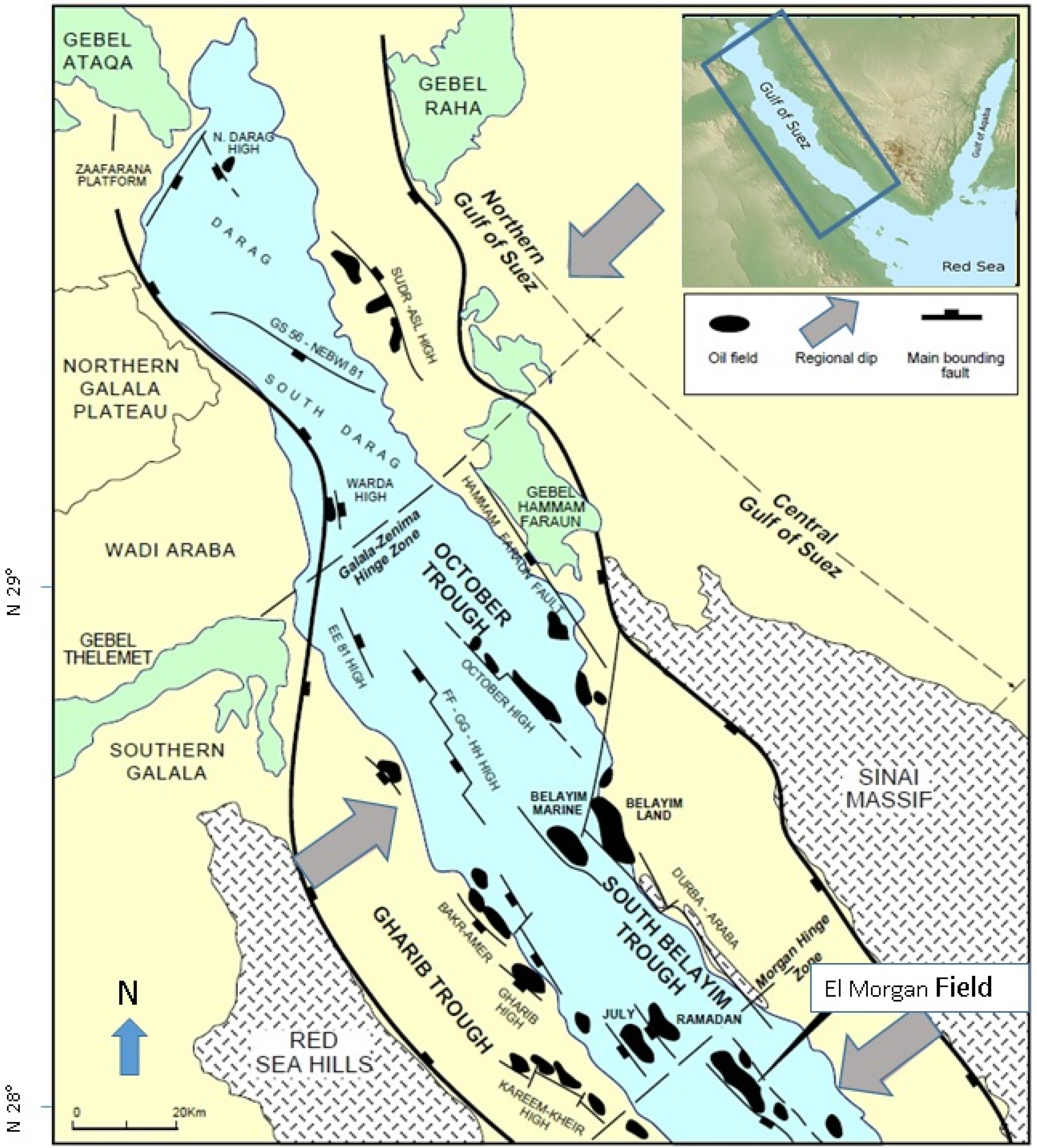
2. Geological Background

For a long time, the GOS Basin (Figure 1) has formed the main hydrocarbon container in Egypt [41,42,43,44,45,46,47]. It is considered one of the most important economic regions in Egypt [41,42,43,44,45,46,47]. The basin is characterized by its specific geological features and complex tectonic history [48,49]. The GOS basin has been the subject of extensive research to discover more about its geological history and natural resource potential [48,50,51,52,53,54,55]. The rifting of the basin started at the Late Oligocene and extended to the Early Miocene, and the basin’s sedimentary succession (Figure 2) has been divided into three sedimentary cycles in relation to rifting [48,56,57], as follows:
The Cambrian to Late Oligocene sedimentary cycle includes mixed siliciclastics and carbonate facies;
The Late Oligocene to Miocene sedimentary cycle contains mixed evaporites, siliciclastics, and carbonate facies;
The Quaternary sedimentary cycle contains mixed evaporites, siliciclastics, and carbonate facies, namely, the El Tor Group.
Figure 2 shows the lithostartigraphy and depositional age of different formations through the basin. The previously mentioned sedimentary cycles are distinguished by the depositional of various lithologies with distinct properties. Sediments such as loose sandstone and depleted sandstone zones are not favorable because they are a source of mud losses while drilling. Swelling shale complicates drilling and causes pipes to become stuck, which is a common problem in the Gulf of Suez Basin [17,18,19,20]. Pressurized shale requires high mud density to be drilled, which is not matched with the depleted sandstone and causes drilling challenges. Moreover, salt is a source for pipes stuck in many fields across the basin, as reported by Radwan et al. [17,18,19,20].
The El Morgan Field is situated in the central province of the basin, where the beds dip southeast (Figure 1), Radwan et al. [17,18,20]. During the Miocene Era (Middle Miocene), the entire GOS Basin was covered by open marine facies that allowed for the deposition of marl facies, as well as submarine fans of the Kareem Formation and Hammam Faraun Member. Its main prospective reservoir sequences are the Middle Miocene formations [41,42,47,56,57,58]. Evaporitic sediments of the South Gharib and Zeit Formations were deposited in the Late Miocene, forming an ultimate seal for hydrocarbons migrating from deeper source rocks (Campanian-Maastrichtian and Eocene organic-rich sediments) to main reservoirs. The lithology variation of the basin and the El Morgan oil field forms obstacles while drilling, where over-pressurized shales, natural fractures, loose sediments, and depleted reservoirs can be found in the same drilled hole [17,18,19,20,58] (Figure 2).

3. Materials and Methods

This analysis relies on conventional well logs (gamma-ray, density, resistivity, and sonic slowness) from five near-vertical wells, as well as pore pressure information from MDT tools. All offset well drilling issues were considered, as well as the detailed methods used to alleviate those issues. The overburden stress was measured first using log data and experimental equations, and then the pore pressure was calculated by calibrating the MDT tools’ pore pressure points. In the next step, the rock elastic and strength parameters were calculated, and the minimum and maximum horizontal stress values were determined using poroelastic equations, and their orientations were directly obtained from a regional database. One model was developed for the studied field, and the displayed data is for the El Morgan A1 well. The main inputs for this model incorporate stress magnitude and directions, well logs, measured data, and relevant parameters.

3.1. Vertical Stress Estimation

The pressure generated by combining the vertical column pressure of various rock layers and the fluids inside at a certain depth is called overburden stress, commonly called vertical stress (Sv) [5,59]. The vertical stress (SV) at a particular depth (H) is calculated using the following equation:
Sv = 0 H ρ ( H ) * g   dH
where Sv is the vertical stress in (psi), g is the gravity constant (9.8 m/s2), and ρ is the total density (gm/cm3). However, in most cases, the density information is not available in the initial intervals of the drilled well, making it difficult to quantify vertical stress. As a result, at the initial intervals from the ground to the target depth, the density can be determined using a linear equation.
The density profile in El Morgan’s shallower section was generated using the Amoco equation, then merged with the recorded density data [17,18,60]. Estimation and measurement methods of in situ stress and PP in the oil and gas industry were listed in Table 1.

3.2. Pore Pressure Estimation

Several authors use indirect pore pressure measurements from well log data such as density, resistivity, and acoustic logs to determine pore pressure [17,18,61,62]. The PP at the reservoir interval is based on the pore pressure gradient obtained from formation test instruments (e.g., modular dynamic tester (MDT), formation integrity test (FIT)) [17,20]. However, widely used equations that use well logs, such as Eaton’s [17,18] equation can be used in non-reservoir zones.
PPg = O B G ( O B G Phyd ) * ( DTn DT ) 3
where PPg denotes the pore pressure gradient, Phyd denotes the hydrostatic pressure (psi),   O B G denotes overburden gradient (ppg), DTn denotes the sonic log value, while DT denotes compressional sonic slowness (μs/ft).
PPg = O B G ( O B G Phyd ) * ( R Rn ) 1.2
where R denotes the deep resistivity logs (ohm-meter (Ω⋅m), while Rn is the deep resistivity log value. MDT tool pressure data has been made available in this analysis at reservoir intervals, while non-reservoir intervals were estimated using the previous equations (Equations (2) and (3)).

3.3. Rock Mechanical Properties Estimation

Rock mechanics parameters such as Young’s modulus, bulk moduli, shear moduli, and Poisson ratio reflect rock sensitivity to variability, which can be calculated both statically and dynamically [11,12,63,64,65,66]. The use of well logs, which include these elastic parameters dynamically, is a faster and less expensive method than measurements of the elastic parameters of rock [5,6,67,68]. In this study, density, compression, and shear velocity logs are used according to the following equations to estimate the dynamic Young’s modulus (Ed) and the dynamic Poisson ratio (ʋd):
ʋ d = Vp 2 2 Vs 2 2 ( Vp 2 Vs 2 )
where νd is dynamic Poisson ratios, ρ is density log value, Vp and Vs are the velocities of compressional and shear waves from log, respectively.
Ed =   RHOB *   Vs 2 [ 3 Vp 2 4 Vs 2 Vp 2 Vs 2 ]
where Ed is dynamic Young’s modulus, ρ is density.
The conversion of dynamic data (Ed and ʋd) to static (Es and νs) is accomplished by calibrating the results of laboratory tests (static) for different rocks. In this study, the generic John Fuller correlation [11,69] was employed by Equations (6) and (7), and the regional core-based measurements were applied in the aforementioned equations.
Es = y 1   Ed y 2  
ʋ s   = ʋ d
where ʋ s is static Poisson ratios, Es is static Young’s modulus, and the two correlation parameters denoted y1 and y2.
The relationship between the uniaxial compressive strength (UCS) and tensile strength (TSTR) parameters and various physical characteristics of rocks represented by well logs was investigated by Fjaer et al. [70]. In this study, the proposed equations for various rock types are used to determine this parameter [71,72,73,74,75].
UCS = 1.35   ( 304.8 DT ) 2.6
TSTR = K * UCS
where K is the coefficient and equal to 0.1 according to Zoback [76].

3.4. Determination of Minimum and Maximum Horizontal Stresses

The minimum horizontal stress (Shmin) can be determined directly from the mini frac test, hydraulic fracture, or LOT/XLOT test. However, the SHmax cannot be determined directly [11,77,78,79]. Even though both of them can be calculated using indirect methods with acceptable accuracy (Table 1). The use of the poroelastic horizontal stress method is one of the conventional methods for indirectly calculating Shmin and SHmax as expressed by Equations (10) and (11) as follows [5,6,76,80,81]:
S hmin = ʋ 1 ʋ   Sv ʋ 1 ʋ α P P + α P P + ʋ E 1 ʋ 2   ʋ h + E 1 ʋ 2   ʋ H
S HMax = ʋ 1 ʋ   Sv ʋ 1 ʋ α P P + α P P + ʋ E 1 ʋ 2   ʋ H + E 1 ʋ 2   ʋ h
where α is Biot coefficient (conventionally = 1),   ʋ h and ʋ H are the tectonic strain in the x and y directions [5,77,80,81]. The main stress orientations have a significant impact on wellbore failure [82,83]. In this study, the orientation of Shmin and SHmax were taken directly from Gupco [84] and compared with the central region of the Gulf of Suez [45,85]. Where the average orientation of Shmin is NE-SW 45°, and the average SHmax is NW-SE 135°.

3.5. DOD Approach

The amount of damage surrounding a wellbore as a function of internal pressure exerted by the drilling fluid is translated by a depth-of-damage model of the target wellbore. This is the volume of rock yielded as a result of drilling fluid pressure acting against near-field stresses to partially support the wellbore wall. First, far-field stresses are converted to near-field stresses, which are then compared to a rock failure criterion in the vicinity of the wellbore. This calculates the lowest allowable drilling fluid pressure that can be maintained while maintaining a predetermined allowable failure margin (e.g., 5%, 10%, etc.) (Figure 3 and Figure 4). When calculating the DOD, the width of the damage zone beyond the wellbore wall into the formation is taken into account (Figure 3, Figure 4 and Figure 5). The basic algorithm calculates stresses at the borehole wall using elastic equations (calculation radius (r) = wellbore radius (a)) [11,39,40,86,87] (Figure 5). At a certain depth inside the formation (i.e., where r > a), the stresses around the borehole and the yield are determined (Figure 5). A depth ratio is a measurement of the extent of damage, as in Equation (12) as follows:
Depth Ratio = (r − a)/a * 100%
The breakout gradient is calculated using the Kirsch equations of stresses across the wellbore at different depth ratios (i.e., 5, 10, and 20 percent). More details about the DOD approach can be found in Frydman & Fontoura [87] and Higgins-Borchardt [39]. The DOD definition is graphically represented in Figure 4 and Figure 5.

3.6. Rock Failure Criterion

To establish the minimum drilling fluid pressure and avoid wellbore compressive failures, the Shmin magnitude was calculated using extended LOT data in this analysis [16,88,89]. After that, the modified lade failure criterion was used [90,91]. The aforementioned failure criterion was applied to follow the same widely used failure criterion in the Gulf of Suez Basin [5,6]. On the other hand, other failure criteria such as Mohr–Coulomb, Moji-Column, and Hoek–Brown can be applied instead of modified Lade. Furthermore, the modified Lade failure criteria were only used to compare the results by applying the same failure criterion model.

4. Results

4.1. Pore Pressure Analysis

The PP model for the El Morgan wells shows hydrostatic trends (normal PP) through the sediments that are deposited after the Zeit Formation mixed sediments (Table 2). The PP ramp was developed and reached up to 10.2 ppg equivalent density (ED) at the lower shale deposits of the Zeit Formation. Another PP incremental increase was observed through the mud deposits of the dominant halite of the S. Gharib Formation, which reached up to 10.6 ppg ED.
The shale deposits of the mid-Miocene section of the Belayim and Kareem formations are still preserving the virgin pressure of between 9.31 and 9.62 ppg ED in an arrangement based on the RFT data. However, the sandstone deposits of the mid-Miocene section of the Hammam Faraun Member (Belayim Formation) were affected by prolonged production and displayed PP ranges between 6.51 and 9.31 ppg ED, according to downhole measurements (i.e., MDT). According to downhole measurements, the sandstone deposits of the mid-Miocene section of the Kareem Formation were affected by prolonged production too, and displayed PP ranges of 5.91–9.62 ppg ED. On the contrary, in between the upper member of the Belayim and Kareem formations, the other three members display normal hydrostatic gradients.

4.2. In Situ Stresses

The vertical stress of the El Morgan wells, which is the overburden in this case, shows values ranging between 16.7 and 17.9 ppg ED through the mixed evaporites and muddy sediments of the Zeit Formation (Figure 6 and Table 2). Through the minor muddy sediments of the dominant evaporite S. Gharib Formation, the overburden magnitude ranged from 17.9 to 18.3 ppg ED. Another incremental increase in overburden magnitude was observed, ranging between 18.31 and 18.8 ppg ED through the Belayim Formation. The overburden magnitude ranged between 18.8 and 18.9 ppg ED through the mid-Miocene section of the Kareem Formation. The caliper readings indicate high washout against salt sections, which are dominant in the Zeit, S. Gharib, and Belayim formations, which affect the log readings and, consequently, the mechanical parameters in the salt intervals. However, such an effect was limited to the salt sections across the borehole, mainly the S. Gharib and Belayim formations, with some shale intervals affected to a lesser degree. Intervals with some uncertainties have been taken into consideration during the model building.
The mechanical properties of the El Morgan oil field have been determined to assist in the definition of horizontal in-situ stresses (Figure 7). According to Barton et al. [92], breakouts occur when the hoop stress is most compressive in the Shmin direction and the stress concentration overwhelms the rock strength. Circumferential tension, which has the least compression at the orientation of the SHmax, causes drilling-induced tensile fractures according to Radwan et al. [85]. The inferred Shmin and SHmax in the El Morgan oil field were reported in Gupco [84], where the average direction of Shmin is oriented NE-SW 45°, and the average SHmax is oriented perpendicular to Shmin NW-SE 135°. This orientation of horizontal stress in the El Morgan Field is consistent with other breakout interpretations in the central GOS region [45].
The Shmin stress magnitude model for the El Morgan wells shows values ranging between 12.7 and 13.8 ppg (ED) through the mixed evaporites and muddy sediments of the Zeit Formation (Figure 7 and Table 3). The Shmin magnitude ranged between 13.7 and 14.2 ppg ED through the minor muddy sediments of the dominant evaporite S. Gharib Formation. However, a significant decrease in Shmin magnitude was observed through the Belayim Formation, ranging between 12.1 and 12.4 ppg ED. As well, the Shmin magnitude ranged between 12.21 and 13.12 ppg ED through the mid-Miocene section of the Kareem Formation.
On the contrary, the SHmax stress magnitude model of the El Morgan wells shows values ranging between 16.2 and 17.7 ppg (ED) through the mixed evaporites and muddy sediments of the Zeit Formation (Figure 7 and Table 3). The SHmax magnitude through the minor muddy sediments of the dominant evaporites of the S. Gharib Formation ranges between 17.7 and 17.9 ppg ED. However, a significant decrease in SHmax magnitude was observed throughout the Belayim Formation, ranging from 17.29 ppg ED at the upper part of the formation to 12.4 ppg ED at the bottom. Furthermore, the SHmax magnitude was found to be between 17.51 and 17.62 ppg ED throughout the Mid-Miocene section of the Kareem Formation.

4.3. Wellbore Stability Analysis

Modeling the wellbore stability of the Zeit Formation inferred a value of 12.42 ppg ED as shear failure through the lower shale deposits. The previous shear failure mud density is the ED that can be used for drilling the shale deposits of the formation without borehole failure with (0%) DOD. This shear failure value is equivalent to the obtained results using the breakout-width concept. The most intriguing aspect of the DOD model used in this study is that it provides three additional values that drillers can use based on drilling conditions. A value of 11.78 ppg ED represents the 5% DOD along the Zeit Formation (Table 3 and Figure 8).
The aforementioned 5% DOD value means that the shale deposits of the mentioned formation can be drilled with this mud density value but with an allowable 5% of borehole failure from the original borehole diameter, which can be managed by applying best drilling practices. Another value of 11.15 ppg ED represents the 10% DOD along the Zeit Formation. The aforementioned 10% DOD value means that the shale deposits of the Zeit Formation can be drilled with this mud density value but with an allowable 10% borehole failure, which can be managed by optimum drilling practice. The third optional value for the Zeit Formation is 9.85 ppg ED, which represents the 20% DOD value. The aforementioned 20% DOD value means that the investigated shale deposits can be drilled with this mud density value but with an allowable 20% borehole failure, which can be managed by drilling practice. Modeling the wellbore stability of the S. Gharib Formation inferred a value of 12.85 ppg ED as a shear failure and a value of 12.27 ppg ED representing 5% DOD. Furthermore, two values of 11.68 and 10.47 ppg ED represent the 10% and 20% DOD in an arrangement (Table 3 and Figure 9). Modeling the wellbore stability of the Belayim Formation inferred a value of 10.06 ppg ED as a shear failure and a value of 9.23 ppg ED representing 5% DOD. Another two values of 8.59 and 8.33 ppg ED represent the 10% and 20% DOD in an arrangement. Modeling the wellbore stability of the Belayim Formation inferred a value of 10.06 ppg ED as a shear failure and a value of 9.23 ppg ED representing 5% DOD. Another two values of 8.59 and 8.33 ppg ED represent the 10% and 20% DOD in an arrangement along the Belayim Formation.
Modeling the wellbore stability of the last drilled sediments of the Kareem Formation inferred a value of 11.6 ppg ED as a shear failure and a value of 10.88 ppg ED representing 5% DOD. Another two values of 10.16 and 8.72 ppg ED belong to the previous formation, and these values represent the 10% and 20% DOD in an arrangement (Table 3 and Figure 10). It is recommended in the studied field to maintain 5%, 10%, or 20% DOD values in reservoir sections based on individual hole conditions, with the goal of mitigating reservoir damage or contamination. However, optimal drilling practice and monitoring are required to meet the drilling target.

5. Discussion

5.1. Breakout-Width Concept vs. Depth-of-Damage Concept: Implications for Drilling

Research into the geomechanical characteristics, pore pressure, natural fracture, and fracture pressure has gained attention from authors because it has various implications for drilling and exploration [92,93,94,95,96,97,98,99,100]. Most geomechanical studies depend on the breakout-width model by Zoback et al. [32] in their models in order to prevent borehole collapse [2,23,33,34,35,36]. The breakout-width model output only provides the safest mud density for drilling; however, in most cases, this value is much higher than the pore pressure, posing challenges in well planning [2,23,32,36,37,38,101,102,103]. The breakout-width model conservative curve narrows the MWW between the shear failure and fracture pressure limits, which lowers the tolerance for mud loss in depleted reservoirs and increases the risk of losses and formation damage. The traditional breakout-width model relies on a slightly overbalanced drilling strategy that provides the best solution to overcome over-pressured zones in boreholes. In addition, since the post-yield behavior related to near-wellbore stresses is not taken into account in the breakout-width model [37,38]. Therefore, other models, such as the DOD, which take the post-yield behavior related to near-wellbore stresses into account may be a better option for complex drilling issues accompanied by different pressure regimes and multi-wellbore instability issues where multiple values of acceptable mud density are provided [39,40]. Using the DOD concept in the studied field entails providing a variety of drilling options that can be used to overcome unexpected incidents that may arise during drilling activities. In other words, it provides various levels of failure risk that can be used as contingency plans in the event of an unexpected incident. Furthermore, the given multi-mud density scenarios assist drillers in being prepared and flexible in the event of unforeseen subsurface conditions. Moreover, the DOD model shed light on the drilling uncertainties and forced the direction of more consideration of such geological and engineering uncertainties in the subsurface systems. When the DOD model’s variable mud density values were compared to the breakout-width concept’s mud density value, the DOD model’s variable mud density values were found to significantly add additional mud density values. The caliper data of the El Morgan’s previous drilled wells using the breakout-width model is compared to the caliper results of the newly investigated well to better understand and compare the behavior of the two investigated models in the El Morgan studied wells. To calculate the DOD percentage in the wells, the caliper reading of the investigated borehole was subtracted from the theoretical hole diameter and then divided by the initial borehole diameter. The final DOD results were translated into percentages related to the theoretical hole radius. As well, previous boreholes were analyzed to obtain the damage percentage in the boreholes. Data from Figure 11 illustrates that the old-drilled wells in the El Morgan Field were drilled with higher mud density and the DOD of these wells is dominant by DOD of 5% or less, indicating a low percent of borehole damage. On the other hand, the current WBS model of the El Morgan-A1 well has various DOD starting from 5% up to 20%, indicating a higher percent of borehole damage but controlled by optimal drilling practice (i.e., controlled drilling parameters).
The DOD, as can be seen, is an improved version of the Breakout-width principle that can provide manageable practical values that can be used in various subsurface conditions. Using the DOD principle in a complex pore pressure regime within the geological column of the studied area will assist in the creation of an underbalanced drilling strategy in complex mature basins in the case of depleted reservoir parts in order to avoid losses. Furthermore, by applying drilling practice to an acceptable amount that can be drilled safely, the drilling can be managed to control the other intervals that have relatively higher pressure. In the traditional breakout-width concept, the mud density window is between shear failure and Shmin. The main advantage of the DOD approach is that it broadens the mud density window to be less than the shear failure with an acceptable amount of failure. Applying the DOD approach in the Gulf of Suez Basin or any basin elsewhere that is suffering from prolonged production associated with highly depleted reservoirs can support the idea of under-balanced drilling in such complex drilling situations. The main advantages and differences between the DOD approach and breakout width have been listed in Table 4.

5.2. Field Challenges and Suggestion for Field Development

In this study, the caliper log was used to determine the breakout zonation in the geological column of the studied wells to define the associated instability issues in the borehole. Breakouts can be defined as the enlarging of the hole diameter due to falling cuttings from the borehole wall. These breakouts have been encountered in mudstone intervals of all drilled formations. Other enlargements of the borehole were detected in the halite section of the Zeit and S. Gharib formations (Figure 6). Drilling in the El Morgan Field faced considerable difficulties at the drilling stage of most wells that ended in the mid-Miocene section of the Kareem Formation [104,105]. Radwan et al. [17,18], Radwan and Sen [5,6,104,105] have previously discussed similar drilling incidents in the neighboring Badri field. Partial losses were encountered during the drilling operation of the high permeable sandstone of the Zeit Formation in most wells of the El Morgan Field. On the contrary, drilling in the same formation was accompanied by tight spots, hole fill, and pressurized shale in four offset wells, indicating the overpressured regime and wellbore instability issues. In this regard, it is highly recommended to use the 5% to 10% DOD MW values in the Zeit Formation interval to maintain low losses and keep marginally higher MW to hold pressurized shale.
Drilling of the S. Gharib Formation was accompanied by salt creep and well flow in all offset wells, indicating the wellbore instability issues. To overcome the salt creeping drilling event, low salinity water was pushed downhole, which enlarged the borehole by a significant amount, reaching more than 16 inches at the halite sections (Figure 6). According to the WBS analysis (Table 3), this formation can be drilled safely using a slightly higher MW than the Zeit Formation. The used casing strategy could control the DOD value in this interval. Separating the S. Gharib Formation interval from the above interval is strongly advised in this regard because higher MW may be required to mitigate saltwater flow, which can increase the mud loss potential in the sandstones of the Zeit Formation interval while salt creep is mitigated.
The first drilled wells in the field were ended by 9 5/8″ of the casing, where the Mid-Miocene reservoirs were at virgin PP status. At present, the reservoir pressure has been decreasing dramatically to sub-normal conditions, which has become a challenging drilling risk during the drilling of these reservoirs. The newly drilled wells in the El Morgan Field have faced partial losses at the reservoir sections of the Kareem and Belayim formations (Figure 6) because of the high mud density applied to the upper overpressure zones as well as some tight spots that have appeared in some wells. For safe drilling, it is better to separate the S. Gharib interval from the deeper sections of the Belayim and Kareem formations that need lower mud density. However, this aforementioned option might be unsuitable in the exploration of deeper sections, so the drilling of the reservoir section with a 5% DOD mud density value according to (Table 3) could decrease losses and keep hold of the upper overpressure zones with a low amount of borehole collapse.
The previously discussed field challenges highlight the complexities of drilling in such depleted fields. As a result, the traditional breakout width and shear failure value alone will not be effective in this field’s development strategy. Applying the DOD approach to the developed model of the El Morgan Field resulted in valuable multi-mud density curves, which can provide flexible MWW in complex drilling sections. The wellbore stability model for the El Morgan wells shows variable values that could be used for safe drilling or manageable drilling with an acceptable certain percentage of failure. At the current depletion status in the El Morgan Field, special attention should also be paid to the drilling fluid characteristics. It is recommended to use drilling fluid with excellent inhibitory properties and sealing characteristics. It should be noted that the seepage time of drilling fluid should be shortened, taking into account reasonable values in engineering practices.
Finally, it should be noted that the success of such a DOD model depends on a better understanding of the geological factors and drilling risks that affect the borehole instability, as well as reasonable value in engineering practices and good well planning according to drilling strategy to reach the exploration targets safely. With the current global depletion of hydrocarbon fields, drilling with mud density below the pore pressure may be required in many drilling cases, especially when drilling is accompanied by fractured intervals with high loss amounts, making underbalance drilling essential for safe drilling. This study provides insights into unconventional techniques such as underbalanced drilling techniques that can be used in mature basins under manageable conditions.

6. Conclusions

In this study, an adequate 1D geomechanical model was performed in the El Morgan Field to interpret the PP and in situ stresses. As well, wellbore stability analysis was performed using the DOD concept. The PP model for the El Morgan wells shows hydrostatic trends (normal PP), overpressure intervals reaching a maximum value of up to 10.6 ppg ED, as well as sub-hydrostatic conditions recording the lowest value of 5.91 ppg ED. The average direction of Shmin in the El Morgan Field is oriented NE-SW 45°, and the average SHmax is oriented perpendicular to Shmin NW-SE 135°. The Shmin stress magnitude model displayed values ranging from 12.1 to 14.2 ppg ED, while the SHmax displayed values ranging from 12.4 to 17.9 ppg ED. Applying the risk-based DOD concept introduces four ED values that can be used while drilling future wells. The first value is the shear failure (0% DOD), the second value is the lowest failure risk value (5% DOD), the third is the medium failure risk value (10% DOD), and the fourth is the highest failure risk value (20% DOD). However, the DOD cannot be used in all cases, such as drilling active high-overpressure zones associated with very low-pressure zones, so field experience and the most effective drilling practice must be used. Traditional approaches may not be effective in reservoir sediments with low mechanical strength, resulting in conservatively high mud weight. For mature hydrocarbon fields, modern approaches such as DOD, which consider the depth of failure around the wellbore, are more appropriate. In contrast to conservative methods, the depth of failure approach performance allows for a more dynamic mud weight window and has more advantages.

Funding

This research was funded by the Priority Research Area Anthropocene under the program “Excellence Initiative—Research University” at the Jagiellonian University in Kraków. The author is thankful to the Faculty of Geography and Geology, Institute of Geological Sciences, Jagiellonian University for the open access funding of this publication.

Data Availability Statement

Not applicable.

Acknowledgments

The author thanks the Gulf of Suez Petroleum Company (GUPCO) and the Egyptian General Petroleum Corporation (EGPC) for granting access to El Morgan Field datasets. This research was funded by the Priority Research Area Anthropocene under the program “Excellence Initiative—Research University” at the Jagiellonian University in Kraków. The author is thankful to the three reviewers for their critical comments that enhanced the manuscript.

Conflicts of Interest

The author declares no conflict of interest.

References

  1. Al-Ajmi, A.M.; Zimmerman, R.W. Stability analysis of vertical boreholes using the Mogi–Coulomb failure criterion. Int. J. Rock Mech. Min. Sci. 2006, 43, 1200–1211. [Google Scholar] [CrossRef]
  2. Zoback, M.D. Reservoir Geomechanics; Cambridge University Press: Cambridge, UK, 2010. [Google Scholar]
  3. Aadnoy, B.; Looyeh, R. Petroleum Rock Mechanics: Drilling Operations and Well Design, 1st ed.; Gulf Professional Publishing: Oxford, UK, 2011; ISBN 9780123855466. [Google Scholar]
  4. Meng, M.; Baldino, S.; Miska, S.Z.; Takach, N. Wellbore stability in naturally fractured formations featuring dual-porosity/single-permeability and finite radial fluid discharge. J. Pet. Sci. Eng. 2019, 174, 790–803. [Google Scholar] [CrossRef]
  5. Radwan, A.; Sen, S. Stress Path Analysis for Characterization of In Situ Stress State and Effect of Reservoir Depletion on Present-Day Stress Magnitudes: Reservoir Geomechanical Modeling in the Gulf of Suez Rift Basin, Egypt. Nat. Resour. Res. 2021, 30, 463–478. [Google Scholar] [CrossRef]
  6. Radwan, A.E.; Sen, S. Characterization of in-situ stresses and its implications for production and reservoir stability in the depleted El Morgan hydrocarbon field, Gulf of Suez Rift Basin, Egypt. J. Struct. Geol. 2021, 148, 104355. [Google Scholar] [CrossRef]
  7. Asaka, M.; Holt, R.M. Anisotropic wellbore stability analysis: Impact on failure prediction. Rock Mech. Rock Eng. 2021, 54, 583–605. [Google Scholar] [CrossRef]
  8. Baouche, R.; Sen, S.; Boutaleb, K. Present day In-Situ stress magnitude and orientation of horizontal stress components in the eastern Illizi basin, Algeria: A geomechanical modeling. J. Struct. Geol. 2020, 132, 103975. [Google Scholar] [CrossRef]
  9. Baouche, R.; Sen, S.; Boutaleb, K. Distribution of pore pressure and fracture pressure gradients in the Paleozoic sediments of Takouazet field, Illizi basin, Algeria. J. Afr. Earth Sci. 2020, 164, 103778. [Google Scholar] [CrossRef]
  10. Baouche, R.; Sen, S.; Sadaoui, M.; Boutaleb, K.; Ganguli, S.S. Characterization of pore pressure, fracture pressure, shear failure and its implications for drilling, wellbore stability and completion design—A case study from the Takouazet field, Illizi Basin, Algeria. Mar. Pet. Geol. 2020, 120, 104510. [Google Scholar] [CrossRef]
  11. Abdelghany, W.K.; Radwan, A.E.; Elkhawaga, M.A.; Wood, D.A.; Sen, S.; Kassem, A.A. Geomechanical modeling using the depth-of-damage approach to achieve successful underbalanced drilling in the Gulf of Suez Rift Basin. J. Pet. Sci. Eng. 2021, 202, 108311. [Google Scholar] [CrossRef]
  12. Abdelghany, W.K.; Hammed, M.S.; Radwan, A.E. Implications of machine learning on geomechanical characterization and sand management: A case study from Hilal field, Gulf of Suez, Egypt. J. Pet. Explor. Prod. Technol. 2022, 1–16. [Google Scholar] [CrossRef]
  13. Li, X.; Gray, K.E. Wellbore stability of deviated wells in depleted reservoir. In Proceedings of the SPE Annual Technical Conference and Exhibition, Houston, TX, USA, 28–30 September 2015; Society of Petroleum Engineers: Houston, TX, USA, 2015. [Google Scholar]
  14. Gao, C.; Gray, K.E. A workflow for infill well design: Wellbore stability analysis through a coupled geomechanics and reservoir simulator. J. Pet. Sci. Eng. 2019, 176, 279–290. [Google Scholar] [CrossRef]
  15. Gao, C.; Gray, K.E. Infill well wellbore stability analysis by considering plasticity, stress arching, lateral deformation and inhomogeneous depletion of the reservoir. J. Pet. Sci. Eng. 2020, 195, 107610. [Google Scholar] [CrossRef]
  16. Zhang, J.; Roegiers, J.-C. Discussion on “Integrating borehole-breakout dimensions, strength criteria, and leak-off test results, to constrain the state of stress across the Chelungpu Fault, Taiwan”. Tectonophysics 2010, 492, 295–298. [Google Scholar] [CrossRef]
  17. Radwan, A.E.; Abudeif, A.M.; Attia, M.M.; Mohammed, M.A. Pore and fracture pressure modeling using direct and indirect methods in Badri Field, Gulf of Suez, Egypt. J. Afr. Earth Sci. 2019, 156, 133–143. [Google Scholar] [CrossRef]
  18. Radwan, A.E.; Abudeif, A.M.; Attia, M.M.; Elkhawaga, M.A.; Abdelghany, W.K.; Kasem, A.A. Geopressure evaluation using integrated basin modelling, well-logging and reservoir data analysis in the northern part of the Badri oil field, Gulf of Suez, Egypt. J. Afr. Earth Sci. 2020, 162, 103743. [Google Scholar] [CrossRef]
  19. Radwan, A.E. Modeling pore pressure and fracture pressure using integrated well logging, drilling based interpretations and reservoir data in the Giant El Morgan oil Field, Gulf of Suez, Egypt. J. Afr. Earth Sci. 2021, 178, 104165. [Google Scholar] [CrossRef]
  20. Radwan, A.E. A multi-proxy approach to detect the pore pressure and the origin of overpressure in sedimentary basins: An example from the Gulf of Suez rift basin. Front. Earth Sci. 2022, 10, 967201. [Google Scholar] [CrossRef]
  21. Aleksandrowski, P.; Inderhaug, O.H.; Knapstad, B. Tectonic structures and wellbore breakout orientation. In Proceedings of the 33rd US Symposium on Rock Mechanics (USRMS), Santa Fe, NM, USA, 3–5 June 1992; OnePetro: Richardson, TX, USA, 1992. [Google Scholar]
  22. Yu, M. Chemical and Thermal Effects on Wellbore Stability of Shale Formations. Ph.D. Thesis, The University of Texas at Austin, Austin, TX, USA, 2002. [Google Scholar]
  23. Ma, T.; Chen, P.; Yang, C.; Zhao, J. Wellbore stability analysis and well path optimization based on the breakout width model and Mogi-Coulomb criterion. J. Pet. Sci. Eng. 2015, 135, 678–701. [Google Scholar] [CrossRef]
  24. Ma, Y.Z. Unconventional resources from exploration to production. In Unconventional Oil and Gas Resources Handbook; Gulf Professional Publishing: Oxford, UK, 2016; pp. 3–52. [Google Scholar] [CrossRef]
  25. Ameen, M.S. Systems and Methods to Predict and Inhibit Broken-Out Drilling-Induced Fractures in Hydrocarbon Wells. U.S. Patent No. 10,557,345, 2 February 2020. [Google Scholar]
  26. Bradley, W.B. Failure of inclined boreholes. J. Energy Resour. Technol. 1979, 101, 232–239. [Google Scholar] [CrossRef]
  27. Plumb, R.A. Influence of Composition and Texture on the Failure Properties of Clastic Rocks. In Rock Mechanics in Petroleum Engineering; OnePetro: Richardson, TX, USA, 1994. [Google Scholar]
  28. Chen, G.; Chenevert, M.E.; Sharma, M.M.; Yu, M. A study of wellbore stability in shales including poroelastic, chemical, and thermal effects. J. Pet. Sci. Eng. 2003, 38, 167–176. [Google Scholar] [CrossRef]
  29. Pasic, B.; Gaurina-Meðimurec, N.; Matanovic, D. Wellbore instability: Causes and consequences/Nestabilnost Kanala Busotine: Uzroci I Posljedice. Rud. Geol. Naft. Zb. 2007, 19, 87. [Google Scholar]
  30. Sen, S.; Kundan, A.; Kalpande, V.; Kumar, M. The present-day state of tectonic stress in the offshore Kutch-Saurashtra Basin, India. Mar. Pet. Geol. 2019, 102, 751–758. [Google Scholar] [CrossRef]
  31. Bagheri, H.; Tanha, A.A.; Doulati Ardejani, F.; Heydari-Tajareh, M.; Larki, E. Geomechanical model and wellbore stability analysis utilizing acoustic impedance and reflection coefficient in a carbonate reservoir. J. Pet. Explor. Prod. Technol. 2021, 11, 3935–3961. [Google Scholar] [CrossRef]
  32. Zoback, M.D.; Moos, D.; Mastin, L.; Anderson, R.N. Well bore breakouts and in situ stress. J. Geophys. Res. Solid Earth 1985, 90, 5523–5530. [Google Scholar] [CrossRef]
  33. Zhou, S. A program to model the initial shape and extent of borehole breakout. Comput. Geosci. 1994, 20, 1143–1160. [Google Scholar] [CrossRef]
  34. Moos, D.; Peska, P.; Finkbeiner, T.; Zoback, M. Comprehensive wellbore stability analysis utilizing quantitative risk assessment. J. Pet. Sci. Eng. 2003, 38, 97–109. [Google Scholar] [CrossRef]
  35. Lee, H.; Moon, T.; Haimson, B.C. Borehole breakouts induced in arkosic sandstones and a discrete element analysis. Rock Mech. Rock Eng. 2016, 49, 1369–1388. [Google Scholar] [CrossRef]
  36. Bahrehdar, M.; Lakirouhani, A. Evaluation of the Depth and Width of Progressive Failure of Breakout Based on Different Failure Criteria, Using a Finite Element Numerical Model. Arab. J. Sci. Eng. 2022, 47, 11825–11839. [Google Scholar] [CrossRef]
  37. Joshi, S.D. Horizontal wells: Successes and failures. J. Can. Pet. Technol. 1994, 33, PETSOC-94-03-01. [Google Scholar] [CrossRef]
  38. Aadnoy, B.; Cooper, I.; Miska, S.; Mitchell, R.F.; Payne, M.L. Advanced Drilling and Well Technology; SPE: Houston, TX, USA, 2009; pp. 301–440. ISBN 978-1-55563-145-1. [Google Scholar]
  39. Higgins-Borchardt, S.; Krepp, T.; Frydman, M.; Sitchler, J. New Approach to Geomechanics Solves Serious Horizontal Drilling Problems in Challenging Unconventional Plays. In Proceedings of the SPE/AAPG/SEG Unconventional Resources Technology Conference, Denver, CO, USA, 12–14 August 2013; pp. 379–388. [Google Scholar] [CrossRef]
  40. Frydman, M. U.S. Patent No. 9,646,115, 2017; U.S. Patent and Trademark Office: Washington, DC, USA, 2017. [Google Scholar]
  41. Radwan, A.E.; Rohais, S.; Chiarella, D. Combined stratigraphic-structural play characterization in hydrocarbon exploration: A case study of Middle Miocene sandstones, Gulf of Suez basin, Egypt. J. Asian Earth Sci. 2021, 218, 104686. [Google Scholar] [CrossRef]
  42. Alsharhan, A.S. Petroleum geology and potential hydrocarbon plays in the Gulf of Suez rift basin, Egypt. AAPG Bull. 2003, 87, 143–180. [Google Scholar] [CrossRef]
  43. Abudeif, A.; Attia, M.; Radwan, A.E. New simulation technique to estimate the hydrocarbon type for the two untested members of Belayim Formation in the absence of pressure data, Badri Field, Gulf of Suez, Egypt. Arab. J. Geosci. 2016, 9, 218. [Google Scholar] [CrossRef]
  44. Abudeif, A.; Attia, M.; Radwan, A.E. Petrophysical and petrographic evaluation of Sidri member of Belayim Formation, Badri field, Gulf of Suez, Egypt. J. Afr. Earth Sci. 2016, 115, 108–120. [Google Scholar] [CrossRef]
  45. Bosworth, W.; Durocher, S. Present-day stress fields of the Gulf of Suez (Egypt) based on exploratory well data: Non-uniform regional extension and its relation to inherited structures and local plate motion. J. Afr. Earth Sci. 2017, 136, 136–147. [Google Scholar] [CrossRef]
  46. Radwan, A.E.; Trippetta, F.; Kassem, A.A.; Kania, M. Multi-scale characterization of unconventional tight carbonate reservoir: Insights from October oil filed, Gulf of Suez rift basin, Egypt. J. Pet. Sci. Eng. 2021, 197, 107968. [Google Scholar] [CrossRef]
  47. Radwan, A.E.; Nabawy, B.S.; Kassem, A.A.; Hussein, W.S. Implementation of Rock Typing on Waterflooding Process During Secondary Recovery in Oil Reservoirs: A Case Study, El Morgan Oil Field, Gulf of Suez, Egypt. Nat. Resour. Res. 2021, 30, 1667–1696. [Google Scholar] [CrossRef]
  48. Robson, D.A. The structure of the Gulf of Suez (Clysmic) rift, with special reference to the eastern side. J. Geol. Soc. 1971, 127, 247–276. [Google Scholar] [CrossRef]
  49. Patton, T.L.; Moustafa, A.R.; Nelson, R.A.; Abdine, S.A. Tectonic evolution and structural setting of the Suez Rift: Chapter 1: Part I. Type Basin: Gulf of Suez. In Interior Rift Basins; American Association of Petroleum Geologists: Tulsa, OK, USA, 1994. [Google Scholar]
  50. Bosworth, W.; McClay, K. Structural and stratigraphic evolution of the Gulf of Suez Rift, Egypt: A synthesis. In Mémoires du Muséum National d’histoire Naturelle; Ziegler, P.A., Cavazza, W., Robertson, A.H.F., Crasquin-Soleau, S., Eds.; Peri-Tethys Memoir 6: Peri-Tethyan Rift/Wrench Basins and Passive Margins.s; Museum National d’Histoire Naturelle de Paris: Paris, France, 2001; Volume 186, pp. 567–606. [Google Scholar]
  51. El Nady, M.M.; Harb, F.M.; Mohamed, N.S. Geochemical characteristics of organic matter from Rudeis and Kareem source rocks, Ras Budran oilfield, central Gulf of Suez, Egypt. Energy Sources Part A Recovery Util. Environ. Eff. 2016, 38, 3273–3282. [Google Scholar] [CrossRef]
  52. Elgendy, N.T.; Abuamarah, B.A.; Nabawy, B.S.; Ghrefat, H.; Kassem, O.M. Pore fabric anisotropy of the cambrian–ordovician Nubia sandstone in the onshore Gulf of Suez, Egypt: A surface outcrop analog. Nat. Resour. Res. 2020, 29, 1307–1328. [Google Scholar] [CrossRef]
  53. Radwan, A.E.; Kassem, A.A.; Kassem, A. Radwany Formation: A new formation name for the Early-Middle Eocene carbonate sediments of the offshore October oil field, Gulf of Suez: Contribution to the Eocene sediments in Egypt. Mar. Pet. Geol. 2020, 116, 104304. [Google Scholar] [CrossRef]
  54. Radwan, A.E.; Abudeif, A.M.; Attia, M.M. Investigative petrophysical fingerprint technique using conventional and synthetic logs in siliciclastic reservoirs: A case study, Gulf of Suez basin, Egypt. J. Afr. Earth Sci. 2020, 167, 103868. [Google Scholar] [CrossRef]
  55. Mansour, A.; Gentzis, T.; Carvajal-Ortiz, H.; Tahoun, S.S.; Elewa, A.M.; Mohamed, O. Source rock evaluation of the Cenomanian Raha Formation, Bakr oil field, Gulf of Suez, Egypt: Observations from palynofacies, RGB-based sporomorph microscopy, and organic geochemistry. Mar. Pet. Geol. 2020, 122, 104661. [Google Scholar] [CrossRef]
  56. Evans, A.L. Neogene tectonic and stratigraphic events in the Gulf of Suez rift area, Egypt. Tectonophysics 1988, 153, 235–247. [Google Scholar] [CrossRef]
  57. Montenat, C.; D’Estevou, P.O.; Purser, B.; Burollet, P.F.; Jarrige, J.J.; Orszag-Sperber, F.; Thiriet, J.P. Tectonic and sedimentary evolution of the Gulf of Suez and the northwestern Red Sea. Tectonophysics 1988, 153, 161–177. [Google Scholar] [CrossRef]
  58. EGPC. Gulf of Suez Oil Fields (A Comprehensive Overview); Egyptian General Petroleum Corporation: Cairo, Egypt, 1996; 736p. [Google Scholar]
  59. Plumb, R.A.; Evans, K.F.; Engelder, T. Geophysical log responses and their correlation with bed to bed stress contrasts in Paleozoic rocks, Appalachian plateau, New York. J. Geophys. Res. 1991, 91, 14509–14528. [Google Scholar] [CrossRef]
  60. Traugott, M. Pore pressure and fracture pressure determination in deep water. World Oil 1997, 218, 68–70. [Google Scholar]
  61. Eaton, B.A. Graphical method predicts geopressures worldwide. World Oil 1972, 182, 51–56. [Google Scholar]
  62. Eaton, B.A. The equation for geopressure prediction from well logs. In Proceedings of the Fall Meeting of the Society of Petroleum Engineers of AIME, Dallas, TX, USA, 28 September–1 October 1975; p. SPE-5544-MS. [Google Scholar] [CrossRef]
  63. Zhang, J. Borehole stability analysis accounting for anisotropies in drilling to weak bedding planes. Int. J. Rock Mech. Min. Sci. 2013, 60, 160–170. [Google Scholar] [CrossRef]
  64. Rafieepour, S.; Jalalifar, H. Drilling Optimization Based on a Geomechanical Analysis Using Probabilistic Risk Assessment, a Case Study from Offshore Iran. In Proceedings of the ISRM Regional Symposium-EUROCK 2014, Vigo, Spain, 27–29 May 2014; p. ISRM-EUROCK-2014-235. [Google Scholar]
  65. Gholami, R.; Aadnoy, B.; Foon, L.Y.; Elochukwu, H. A methodology for wellbore stability analysis in anisotropic formations: A case study from the Canning Basin, Western Australia. J. Nat. Gas Sci. Eng. 2017, 37, 341–360. [Google Scholar] [CrossRef]
  66. Elkatatny, S.; Mahmoud, M.; Mohamed, I.; Abdulraheem, A. Development of a new correlation to determine the static Young’s modulus. J. Pet. Explor. Prod. Technol. 2018, 8, 17–30. [Google Scholar] [CrossRef]
  67. Perras, M.A.; Diederichs, M.S. A Review of the Tensile Strength of Rock: Concepts and Testing. Geotech. Geol. Eng. 2014, 32, 525–546. [Google Scholar] [CrossRef]
  68. Han, Y.; Liu, C.; Phan, D.; AlRuwaili, K.; Abousleiman, Y. Advanced Wellbore Stability Analysis for Drilling Naturally Fractured Rocks. In Proceedings of the SPE Middle East Oil and Gas Show and Conference, Manama, Bahrain, 15 March 2019; Society of Petroleum Engineers: Houston, TX, USA, 2019. [Google Scholar]
  69. Schlumberger. Techlog Pore Pressure Prediction and Wellbore Stability Analysis Workflow/Solutions Training; Schlumberger: Houston, TX, USA, 2015. [Google Scholar]
  70. Fjaer, E.; Horsrud, P.; Raaen, A.M.; Risnes, R.; Holt, R.M. Petroleum Related Rock Mechanics; Elsevier: Amsterdam, The Netherlands, 1992; Volume 33, ISBN 9780080868912. [Google Scholar]
  71. Chang, C.W.; Okawa, D.; Majumdar, A.; Zettl, A. Solid-state thermal rectifier. Science 2006, 314, 1121–1124. [Google Scholar] [CrossRef] [PubMed]
  72. Chang, C.; Zoback, M.D.; Khaksar, A. Empirical relations between rock strength and physical properties in sedimentary rocks. J. Pet. Sci. Eng. 2006, 51, 223–237. [Google Scholar] [CrossRef]
  73. Horsrud, P. Estimating mechanical properties of shale from empirical correlations. SPE Drill. Complet. 2001, 16, 68–73. [Google Scholar] [CrossRef] [Green Version]
  74. Lucier, A.; Zoback, M.; Gupta, N.; Ramakrishnan, T.S. Geomechanical aspects of CO2 sequestration in a deep saline reservoir in the Ohio River Valley region. Environ. Geosci. 2006, 13, 85–103. [Google Scholar] [CrossRef]
  75. Darvishpour, A.; Seifabad, M.C.; Wood, D.A.; Ghorbani, H. Wellbore stability analysis to determine the safe mud weight window for sandstone layers. Pet. Explor. Dev. 2019, 46, 1031–1038. [Google Scholar] [CrossRef]
  76. Zoback, M.D. Reservoir Geomechanics; Stanford University: Stanford, CA, USA, 2007. [Google Scholar]
  77. Al-Qahtani, M.Y.; Zillur, R. A mathematical algorithm for modeling geomechanical rock properties of the Khuff and Pre-Khuff reservoirs in Ghawar field. In Proceedings of the SPE Middle East Oil Show, Manama, Bahrain, 17 March 2001; Society of Petroleum Engineers: Houston, TX, USA, 2001. [Google Scholar]
  78. Higgins, S.M.; Goodwin, S.A.; Bratton, T.R.; Tracy, G.W. Anisotropic stress models improve completion design in the Baxter Shale. In Proceedings of the SPE Annual Technical Conference and Exhibition, Denver, CO, USA, 21–24 September 2008. [Google Scholar]
  79. Ostadhassan, M.; Zeng, Z.; Zamiran, S. Geomechanical modeling of an anisotropic formation-Bakken case study. In Proceedings of the 46th US Rock Mechanics/Geomechanics Symposium, Chicago, IL, USA, 24–27 June 2012; OnePetro: Richardson, TX, USA, 2012. [Google Scholar]
  80. Thiercelin, M.J.; Plumb, R.A. A core-based prediction of lithologic stress contrasts in east Texas formations. SPE Form. Eval. 1994, 9, 251–258. [Google Scholar] [CrossRef]
  81. Zhang, Y.; Zhang, J. Lithology-dependent minimum horizontal stress and in-situ stress estimate. Tectonophysics 2017, 703–704, 1–8. [Google Scholar] [CrossRef]
  82. Higgins-Borchardt, S.; Sitchler, J.; Bratton, T. Geomechanics for unconventional reservoirs. In Unconventional Oil and Gas Resources Handbook; Gulf Professional Publishing: Oxford, UK, 2016; pp. 199–213. [Google Scholar]
  83. Moos, D.; Zoback, M.D. Utilization of observations of well bore failure to constrain the orientation and magnitude of crustal stresses: Application to continental, Deep Sea Drilling Project, and Ocean Drilling Program boreholes. J. Geophys. Res. Solid Earth 1990, 95, 9305–9325. [Google Scholar] [CrossRef]
  84. GUPCO. Reegional Geomechanical Database Validations in the Gulf of Suez Region; Internal Report; GUPCO: Hurgada, Egypt, 2018. [Google Scholar]
  85. Radwan, A.E.; Abdelghany, W.K.; Elkhawaga, M.A. Present-day in-situ stresses in Southern Gulf of Suez, Egypt: Insights for stress rotation in an extensional rift basin. J. Struct. Geol. 2021, 147, 104334. [Google Scholar] [CrossRef]
  86. Kirsch, C. Die theorie der elastizitat und die bedurfnisse der festigkeitslehre. Z. Des Ver. Dtsch. Ing. 1898, 42, 797–807. [Google Scholar]
  87. Frydman, M.; Fontoura, S.A.D. Wellbore stability considering thermo-porous elastic effects. In Proceedings of the Rio Oil & Gas Conference, Rio de Janeiro, Brazil, 16–19 October 2000. [Google Scholar]
  88. Ju, W.; Shen, J.; Qin, Y.; Meng, S.; Li, C.; Li, G.; Yang, G. In-situ stress distribution and coalbed methane reservoir permeability in the Linxing area, eastern Ordos Basin, China. Front. Earth Sci. 2018, 12, 545–554. [Google Scholar] [CrossRef]
  89. Bahrami, B.; Sadatshojaie, A.; Wood, D.A. Assessing Wellbore Stability with a Modified Lade Failure Criterion. J. Energy Resour. Technol. 2020, 142, 083004. [Google Scholar] [CrossRef]
  90. Ewy, R.T. Wellbore-stability predictions by use of a modified Lade criterion. SPE Drill. Complet. 1999, 14, 85–91. [Google Scholar] [CrossRef]
  91. Lade, P.V. Three-parameter failure criterion for concrete. J. Eng. Mech. Div. Am. Soc. Civ. Eng. 1982, 108, 850–863. [Google Scholar] [CrossRef]
  92. Li, C.; Luo, X.; Zhang, L.; Fan, C.; Xu, C.; Liu, A.; Lei, Y. New understanding of overpressure responses and pore pressure prediction: Insights from the effect of clay mineral transformations on mudstone compaction. Eng. Geol. 2022, 297, 106493. [Google Scholar] [CrossRef]
  93. Barton, C.A.; Moos, D.; Peska, P.; Zoback, M.D. Utilizing wellbore image data to determine the complete stress tensor: Application to permeability anisotropy and wellbore stability. Log Anal. 1997, 38, SPWLA-1997-v38n6a1. [Google Scholar]
  94. Li, C.; Zhang, L.; Luo, X.; Lei, Y.; Yu, L.; Cheng, M.; Wang, Z. Overpressure generation by disequilibrium compaction or hydrocarbon generation in the Paleocene Shahejie Formation in the Chezhen Depression: Insights from logging responses and basin modeling. Mar. Pet. Geol. 2021, 133, 105258. [Google Scholar] [CrossRef]
  95. Li, H.; Tang, H.; Qin, Q.; Zhou, J.; Qin, Z.; Fan, C.; Zhong, C. Characteristics, formation periods and genetic mechanisms of tectonic fractures in the tight gas sandstones reservoir: A case study of Xujiahe Formation in YB area, Sichuan Basin, China. J. Pet. Sci. Eng. 2019, 178, 723–735. [Google Scholar] [CrossRef]
  96. Hu, L. A review of mechanical mechanism and prediction of natural fracture in shale. Arab. J. Geosci. 2022, 15, 474. [Google Scholar] [CrossRef]
  97. Ramdhan, A.M.; Goulty, N.R. Overpressure and mudrock compaction in the Lower Kutai Basin, Indonesia: A radical reappraisal. AAPG Bull. 2011, 95, 1725–1744. [Google Scholar] [CrossRef]
  98. Ramdhan, A.M.; Goulty, N.R. Overpressure-generating mechanisms in the Peciko field, lower Kutai Basin, Indonesia. Pet. Geosci. 2010, 16, 367–376. [Google Scholar] [CrossRef]
  99. Li, J.; Li, H.; Yang, C.; Wu, Y.J.; Gao, Z.; Jiang, S.L. Geological characteristics and controlling factors of deep shale gas enrichment of the Wufeng-Longmaxi Formation in the southern Sichuan Basin, China. Lithosphere 2022, 4737801. [Google Scholar] [CrossRef]
  100. Li, H.; Zhou, J.L.; Mou, X.Y.; Guo, H.X.; Wang, X.X.; An, H.Y.; Mo, Q.W.; Long, H.Y.; Dang, C.X.; Wu, J.F.; et al. Pore structure and fractal characteristics of the marine shale of the Longmaxi Formation in the Changning Area, Southern Sichuan Basin, China. Front. Earth Sci. 2022, 10, 1018274. [Google Scholar] [CrossRef]
  101. Zhang, W.; Gao, J.; Lan, K.; Liu, X.; Feng, G.; Ma, Q. Analysis of borehole collapse and fracture initiation positions and drilling trajectory optimization. J. Pet. Sci. Eng. 2015, 129, 29–39. [Google Scholar] [CrossRef]
  102. Zoback, M.D.; Barton, C.A.; Brudy, M.; Castillo, D.A.; Finkbeiner, T.; Grollimund, B.R.; Moss, D.B.; Peska, P.; Ward, C.D.; Wiprut, D.J. Determination of stress orientation and magnitude in deep wells. Int. J. Rock Mech. Min. Sci. 2003, 40, 1049–1076. [Google Scholar] [CrossRef]
  103. Zhang, H.; Yin, S.; Aadnoy, B.S. Poroelastic modeling of borehole breakouts for in-situ stress determination by finite element method. J. Pet. Sci. Eng. 2018, 162, 674–684. [Google Scholar] [CrossRef]
  104. Radwan, A.E.; Sen, S. Stress path analysis of the depleted middle Miocene clastic reservoirs in the Badri Field, Gulf of Suez Rift Basin, Egypt. In Proceedings of the SPE Annual Technical Conference and Exhibition, Dubai, United Arab Emirates, 21 September 2021; OnePetro: Richardson, TX, USA, 2021. [Google Scholar]
  105. Radwan, A.E.; Sen, S. Stress path analysis of the depleted Miocene clastic reservoirs in the El Morgan Oil Field, Offshore Egypt. In Proceedings of the 55th US Rock Mechanics/Geomechanics Symposium, Online, 18–25 June 2021; OnePetro: Richardson, TX, USA, 2021. [Google Scholar]
Figure 1. General location map of the Gulf of Suez Basin displays the key features of the basin, as well as the location of the El Morgan Field.
Energies 15 07872 g001
Figure 2. Lithostratigraphic column of the syn-rift and post-rift sediments in the El Morgan Field.
Energies 15 07872 g002
Figure 3. Stress and wellbore damage are depicted in this diagram. (A) The borehole’s maximum and minimum horizontal stress directions, (B) mud weight, and various bottom-hole pressures. ESD and ECD are the corresponding static and dynamic density in an arrangement, and MW is the mud window.
Energies 15 07872 g003
Figure 4. The DOD approach schematic diagrams show the consequences of 5%,10%, and 20% wellbore damage.
Energies 15 07872 g004
Figure 5. (A) A schematic for hole and the diameters used in equation 12. (B) The DOD approach schematic diagrams modified after [11,40,69,87]. The wellbore is failing to produce caving when the yield factor exceeds one (green area in the figure below) If the yield factor is greater than one, it indicates that the material is failing and may deform and/or fail, resulting in cavings (green area in the figure). It should be noted that the yield function used here is built into the commercial software and is not available in the form of an equation. (The reader is directed to the Web version of this article for interpretation of the color references in this figure legend.). Note: MWT refer to mud weight.
Energies 15 07872 g005
Figure 6. The pore pressure with well logging model of the El Morgan-A1 well. Track 1 (Depth), Track 2 (Picks), Track 3 (Lithology), Track 4 (Sonic), Track 5 (Density), Track 6 (GR), Track 7 (vertical stress SV, Shmin, SHmax), Track 8 (Caliber).
Energies 15 07872 g006
Figure 7. The mechanical properties model and in situ stresses for El Morgan-A1 well. Track 1 (Depth), Track 2 (Picks), Track 3 (Lithology), Track 4 (Youngs Modulus and Poisson ration), Track 5 (tensile strength and USC), Track 6 (VP, VS), Track 7 (Vertical stress, Shmin, SHmax).
Energies 15 07872 g007
Figure 8. WBS model of Zeit Formation in El Morgan -A1 well. Track 1 (Lithology), Track 2 (Depth), Track 3 (Picks), Track 4 (Hole deviation and Azimuth), Track 5 (mechanical properties), Track 6 (Vertical stress, Shmin, SHmax, and pore pressure), Track 7 (mud weight window). For the different colors in track 7, readers should refer to Figure 4 in this article.
Energies 15 07872 g008
Figure 9. WBS model of South Gharib Formation in El Morgan-A1 well. Track 1 (Lithology), Track 2 (Depth), Track 3 (Picks), Track 4 (Hole deviation and Azimuth), Track 5 (mechanical properties), Track 6 (Vertical stress, Shmin, SHmax, and pore pressure), Track 7 (mud weight window). For the different colors in track 7, readers should refer to Figure 4 in this article.
Energies 15 07872 g009
Figure 10. WBS model of Kareem Formation in El Morgan-A1 well. Track 1 (Lithology), Track 2 (Depth), Track 3 (Picks), Track 4 (Hole deviation and Azimuth), Track 5 (mechanical properties), Track 6 (Vertical stress, Shmin, SHmax, and pore pressure), Track 7 (mud weight window). For the different colors in track 7, readers should refer to Figure 4 in this article.
Energies 15 07872 g010
Figure 11. Comparison between the depth of damage in the current and previous drilled wells in the El Morgan Field.
Energies 15 07872 g011
Table 1. In situ stress measurements and estimation techniques in the oil and gas industry.
Measurement VariableType of StressEstimation TechniquesMeasurement Techniques
Pore PressurePPResistivityDrill-Stem Test
SonicRepeat Formation Test
(RFT)
DensityModular Dynamic Test (MDT)
Seismic Velocity
Used Mud Weight
Stress MagnitudeSv Density Log
SH maxBreakout--------
Mud Weight
Wellbore Failure Observations
SH minExtended LOT/LOTHydraulic Fracturing
Lost Circulation Minifrac
Formation Integrity Testextended LOT
(DIF) Drilling Induced fractures
Stress OrientationSH max or SH minFault DirectionCross Diploe
Mini-frac
Natural Fault DirectionBreakouts
(DIF) Drilling-induced Fractures
Hydraulic Fracture Test
Table 2. The developed pore pressure and overburden magnitudes of El Morgan Field.
Formation and MembersPP MagnitudeOVB Magnitude
MINMaxMINMax
ppgppgppgppg
Zeit Formation8.7010.2016.7017.90
S. Gharib Formation10.6010.6017.9018.30
H. FARAUN Member6.529.3118.3118.51
FEIRAN Member8.708.7018.5018.60
SIDRI Member8.708.7018.6018.70
BABA Member8.708.7018.7018.80
KAREEM Formation5.919.6218.8218.91
Table 3. The developed in situ stresses and depth-of-damage values of El Morgan oil field.
FormationDepth of Damage %Sv MagnitudeShmin MagnitudeSHmax Magnitude
Shear Failure 0% DOD5% DOD10% DOD20% DODMINMaxMINMaxMINMax
ppgppgppgppgppgppgppgppgppgppg
Zeit12.4211.7811.159.8516.717.912.713.816.217.7
S. Gharib12.8512.2711.6810.4717.918.313.7114.2217.717.9
Belayim10.069.238.598.3318.3118.812.112.417.2917.85
KAREEM11.610.8810.168.7218.8218.9112.2113.1217.5117.62
Table 4. The breakout-width concept versus the depth-of-damage approach.
AttributesDOD ApproachBreakout-Width Approach
OutputOutput curves are fourOutput curve is one
Mud density windowThe low, medium, and high-risk mud density, in addition to the safest mud densityThe safest mud density
Mud Density valuesFlexible valuesFixed value
Geological uncertaintyEffective in the event of unforeseen geological situations (e.g., faults, unexpected pore pressure, etc.)True only if the geology is the same as expected (e.g., it possibly does not operate in horizontal wells)
Directional wellsIn both vertical and deviated wells, it could operate.In both vertical and deviated wells, it could operate. In horizontal wells, it does not function perfectly.
Publisher’s Note: MDPI stays neutral with regard to jurisdictional claims in published maps and institutional affiliations.

