Article

Structure Optimization Research Based on Numerical Simulation of Flow Field in Ammonia-Based Wet Sintering Flue Gas Desulfurization

1
State Grid Henan Electric Power Research Institute, Zhengzhou 450052, China
2
Wuhan Longking Science & Technology Co., Ltd., Wuhan 430205, China
3
School of Power and Mechanical Engineering, Wuhan University, Wuhan 430072, China
*
Author to whom correspondence should be addressed.
Energies 2022, 15(20), 7771; https://doi.org/10.3390/en15207771
Submission received: 25 August 2022 / Revised: 5 October 2022 / Accepted: 10 October 2022 / Published: 20 October 2022

Abstract

:
Although more and more desulfurization equipment has been put into use in sintering plants, how to effectively remove sulfur dioxide from sintering flue gas in a desulfurization tower is still a great challenge in China. The desulfurization tower, as a critical part, needs further improvement and optimization. Therefore, based on the numerical simulation of the flow field of the ammonia-based wet desulfurization tower for sintering flue gas, ANSYS CFX is applied to conduct structural optimization research. Comparing the flow field distribution under different structure conditions, the results show that the flue gas distribution of the dual inlet tower is more uniform than that of the single inlet tower. The designed baffle not only effectively blocks the entry of the spray slurry, but also improves the flue gas distribution; the deflector with its simple structure, convenient operation, and stepped distribution installed in the entrance section can improve the uniformity of the flow field distribution. Based on the comprehensive analysis, these optimized structures are recommended in the design of an ammonia-based wet sintering flue gas desulfurization tower. This work not only develops a simulation of the desulfurization tower but also provides practical structures.

1. Introduction

In recent years, sulfur dioxide (SO2) emissions from the iron and steel industry have attracted worldwide attention. SO2 mainly produced in the sintering process accounts for about 60% of annual emissions from iron and steel plants. Reducing SO2 has been a great challenge for sintering flue gas [1,2], especially in China. As environmental protection requirements become more and more stringent, more and more desulfurization devices have been put into use in sintering plants to reduce SO2 emissions.
Wet Flue Gas Desulfurization (WFGD) technology is the most widely used desulfurization technology in the world. Among them, the ammonia-based WFGD technology, compared with other WFGD technologies, is recognized as one of the most popular methods because it has higher economic efficiency, a more efficient desulfurization process, and useful by-products, and has been successfully installed and operated in coal-fired power plants [3,4,5]. However, due to the peculiarities of sintering flue gas, which is quite different from that of coal-fired power plants, these technologies cannot be simply transferred to the desulfurization of steel sintering, although a great deal of research has been carried out to develop the technology. So far, the application of ammonia-based WFGD is not yet mature in large-scale sintering enterprises, and particularly in single-tower technology, the phenomena of “ammonia escape” and “aerosol” are very serious [6,7]. Therefore, further analysis should be conducted, focusing on the specific sintering process of iron and steel and optimizing the desulfurization technology.
As we know, the desulfurization tower is one of the important components of the WFGD flue gas desulfurization system. The spray tower is the most frequently installed scrubber in the WFGD device, and its design structure will have a great influence on the gas-liquid two-phase flow field, thereby affecting desulfurization efficiency. For the ammonia-based WFGD system, many scholars and research institutions have carried out a lot of experiments and theoretical analysis, but there is little specific information about the simulation optimization of the desulfurization tower for sintering flue gas [8,9,10,11,12]. At present, CFD technology has been extensively used in the investigation of the flow field for the tower of desulfurization. Zhu et al. and Zhang et al. in our research group developed models using ANSYS CFX to calculate the flow field of a full-scale tower with ammonia absorption [13,14], but only for specific equipment and structures. Zhu et al. first successfully simulated the gas-liquid two-phase flow field in a full-size single tower for the sintering flue gas desulfurization tower by using ANSYS CFX software, in which the demist area was simulated as a porous medium area. Compared with the distribution of the flow field under different spray levels, the combination model of second and third spray levels will make the flow field more uniform, gas-liquid contact time longer and conductive to heat transfer [13]; Zhang et al. pushed further research to a full-scale double tower of ammonia-based wet flue gas desulfurization where ANSYS CFX software was used to simulate the operating conditions of a sintering plant to study the flow field without fluid spray and with fluid spray, and according to the results, the gas flow distribution in the evaporating tower was non-uniform and needed to continue to optimization. The spray flow in both towers was more uniform [14]; based on the simulation research results, it is found that more efforts should be made to further optimize the tower structure in view of the current operating desulfurization effect of sintering flue gas, then improve the operating conditions in the tower.
A two phases flow structure is one of the key problems to meet the requirement of reactions for the industrial desulfurization process. In order to improve the uniformity of gas distribution and strengthen the interaction between gas and slurry phases, great efforts have been made to change the flow pattern of the two phases through precise internal devices [15,16,17,18], such as flow pattern controlling unit, rod banks sieve tray, and groove separator. Montanes et al. [19] demonstrated that the synergistic rings slowed down the channeling of flue gas along the wall and improved the removal efficiency by approximately 4%. Chen et al. [20] found that the inlet scrubber with deflectors could efficiently avoid the localized high-speed gas flow, during which desulfurization efficiency increased by about 3%. Tseng et al. [21] added perforated sieve trays into the desulfurization spray tower with the consideration of chemical effects and concluded that the perforated sieve trays can increase desulfurization efficiency. Zhen et al. [22] optimized the flow field by adding a FPC (flow pattern controlling) device to the desulfurization spray tower, and compared with the common spray tower without a perforated plate, the desulfurization performance of the FPC device is markedly improved. Jin et al. [23] studied the internal optimization mechanism of the deflector desulfurization spray tower (DST) and the rod bank desulfurization spray tower (RBST), and the results show that there are gas-liquid contact intensification effects in DST and RBST. Accordingly, there was more work as well as the above-mentioned focus on structure optimization, however, there was little research conducted for the sintering flue gas desulfurization spray tower.
Therefore, based on the previous work, the aim of this work is to develop new internals and discuss the effect of structure on a full-scale sintering flue gas desulfurization tower with ammonia absorption by comparing the flow field of gas-liquid two-phase. Based on the study, the design pattern of the WFGD system was established to manage the tower efficiently and reliably.

2. Models and Assumptions
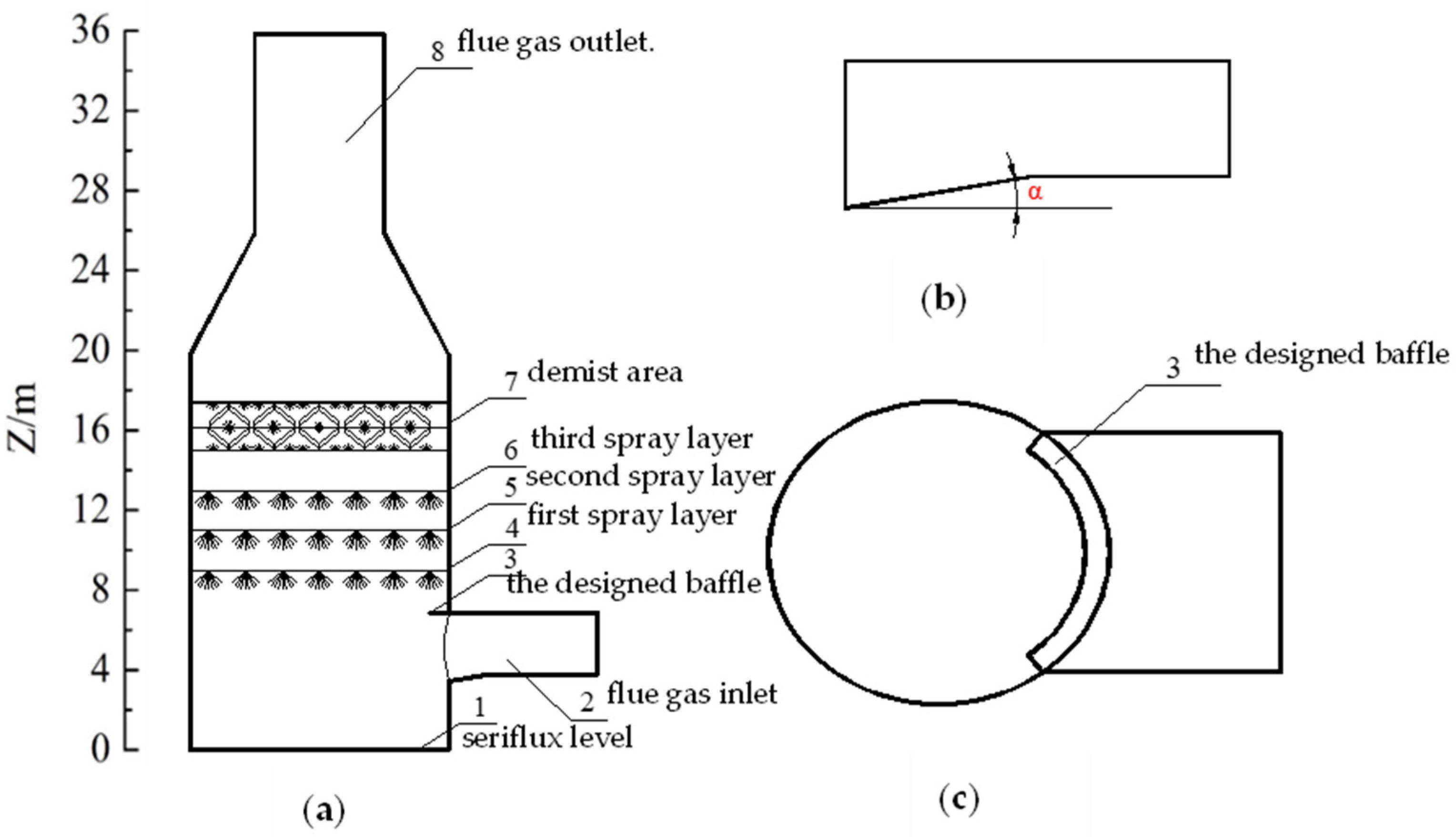
2.1. Physical Model

This paper takes the ammonia flue gas desulfurization spray tower of a large-sized sintering strand in an iron and steel enterprise as the research object. The flue gas is drawn from the outlet flue of the fan of each sintering machine, and it enters the absorption tower and flows upward after being pressurized by the booster fan. Then the flue gas is in countercurrent contact with the ammonium sulfate slurry droplets in the spray area, resulting in mass transfer and absorption reactions to remove SO2 in the flue gas. Most of the droplets contained in the flue gas are removed by the demister, and finally discharged into the atmosphere through the straight exhaust chimney at the top of the absorption tower. The slurry droplets, after absorbing SO2, fall into the slurry pool. There are three staggered spray layers in the spray area, and 108 spiral nozzles are installed on each layer. Gas-liquid two-phase characteristics are mainly studied in this area. The inlet flue pipe and outlet chimney are relatively long, so only one section is selected for analysis in this paper. It is assumed that the flue gas is uniformly distributed on the inlet flue cross section with equal velocity, and the inlet direction is parallel to the flue axis.
This paper focuses on the flue gas above the slurry surface and the flow field distribution of the spray slurry in the tower. The tower body structure is constructed according to the actual size to ensure that the calculation results have guiding significance for the design and operation of the absorption tower. The simplified physical model is shown in Figure 1. The basic parameters of the numerical simulation of the spray tower are shown in Table 1.

2.2. Grid Generation

In this paper, CFX software is used to conduct a three-dimensional numerical simulation of the flow field of the desulfurization spray tower. The physical simplified model is established in UG and then imported into ICEM CFD for grid generation. According to the characteristics of the ammonia desulfurization spray tower, the physical model is simplified and modified, and the effect of spray pipelines on the flow field is temporarily not considered. The porous medium model is used to replace the demister in CFX, and only the effect of resistance is considered. Considering the difficulty of grid generation, computation speed, and convergence, the hexahedral structure grid is adopted. The grid quality is checked from two aspects: the minimum internal angle of each grid element is greater than 18°, and the ratio of the minimum Jacobian matrix to the maximum Jacobian matrix determinant is greater than 0.7. At the same time, to obtain the solution as accurately as possible with as few grids as possible and ensure a reasonable calculation time, the results are verified by grid independence.

2.3. Mathematical Model

(1)
Continuity equation
ρ t + ρ u x + ρ v y + ρ w z = 0
where ρ is fluid density; t is time; u ¯ is velocity vector; u, v, and w are the components of the velocity vector u ¯ in the x, y, and z directions, respectively.
(2)
Momentum equation
ρ u t + d i v ρ u u = p x + τ x x x + τ y x y + τ z x z + F x
ρ v t + d i v ρ v u = p y + τ x y x + τ y y y + τ z y z + F y
ρ w t + d i v ρ w u = p z + τ x z x + τ y z y + τ z z z + F z
where p is pressure on the fluid microelement; τxx, τxy, and τxz are the components of the viscosity stress τ on the surface of the fluid element; Fx, Fy, and Fz are the components of the force on the microelement in the x, y, and z directions, which include gravity and interfacial interaction from the liquid discrete phase.
(3)
Energy equation
ρ T t + ρ u T x + ρ v T y + ρ w T z    = x k c p T x + y k c p T y + z k c p T z + S T
where cp is specific heat capacity; k is the heat transfer coefficient of the fluid; ST is viscous dissipation.
(4)
RNG k-ε model equation
On the basis of previous studies [13], the RNG k-ε model was better than the standard k-ε model in turbulent flow simulation when considering the average flow in rotating flows, so this paper used it to simulate the flue gas.
t ρ k + x i ρ k u i = x j μ + μ t σ k k x j + P k ρ ε
t ρ ε + x i ρ ε u i = x j μ + μ t σ ε R N G ε x j + ε k C ε 1 R N G P k C ε 2 R N G ρ ε
μ e f f = μ g + μ t
p = p + 2 3 ρ k
μ t = C μ ρ k 2 ε
P k = μ t U U + U T 2 3 U 3 μ t U + ρ k + P k b
C ε 1 R N G = 1.42 f η
f η = η 1 η 4.38 1 + β R N G η 3
η = p k ρ C μ R N G ε
where k was the turbulence kinetic energy; ε was the turbulence eddy dissipation; μeff is the effective viscosity; P’ is the corrected pressure; μt is the turbulence viscosity.
(5)
Equation of motion for droplet particles
In this paper, the effects of gravity and drag on the droplets are mainly considered. According to the force analysis of the droplets in the flue gas flow field, the motion equation of the droplet particles can be expressed as [24]:
d u p d t = F D u g u p + g ρ p ρ g ρ p
where F D ( u g u p ) is the drag force per unit mass of the particles subjected to flue gas, and its expression is as follows:
F D = 18 μ ρ p d p 2 C D Re 24
where Re is the relative Reynolds number (or particle Reynolds number), which is defined as:
Re = ρ p d p u p u g μ
CFX provides three empirical models for the drag coefficient between the continuous phase and the discrete phase. For the spray droplet particles in the spray tower, the Schiller–Naumann model is chosen in this paper, and the relevant equations are as follows:
C D = 24 Re 1 + 0.15 Re 0.687
where ug is the flue gas flow rate; Up is the particle velocity; μ is the hydrodynamic viscosity; ρg is the fluid density; ρp is the particle density; dp is the particle diameter; g is the acceleration of gravity.
(6)
Porous medium model
The porous medium model which was applied in most studies [25], is also carried out to approximately simulate the demister area in the desulfurization spray tower in order to reduce the complexity of analysis in the current work, and the model is simplified by determining different parameters such as volume porosity or surface porosity. The pressure loss of the flow in the porous medium is determined by the momentum equation of the porous medium. The porous medium model is based on the Navier–Stokes equation and Darcy’s law, and the convective and diffusional phases are retained, which can be applied to the flows in rod or tube bundles where the effects of two terms are important.

2.4. Assumptions and Simulation Verification

Due to the complex structure of the tower, it is hard to compute all processes exactly by mathematical theory. To better discuss the process in the WFGD tower, some assumptions are as follows:
(1)
There is only 15% O2, 68.694% N2, 10% H2O, 5.7% CO2, 0.548% CO, 0.037% SO2, and 0.021% NO, in the gas phase, and the gas phase is regarded as incompressible Newtonian fluid.
(2)
The seriflux consists of NH4HSO3, (NH4)2SO3, and (NH4)2SO4. Other components are neglected. The spray droplet particles are spherical particles of the same size. The collision is considered a perfectly inelastic collision between the particle and the wall.
(3)
The influence of components such as the tower spray pipe on the flow field is ignored.
(4)
The demist area is simulated as a porous media region, a specified pressure drop is 100 Pa, and the main parameters are set in accordance with the true conditions.
(5)
The seriflux pond is regarded as a solid wall, and the interaction between the liquid level fluctuation and the flue gas is ignored. The wall is regarded as a no-slip insulation wall.
(6)
The mass transfer as well as reactions are ignored between the flue gas and droplets.
(7)
To simplify the modeling, the chimney is only 10 m, the horizontal flue is 5 m, and the gas velocity distribution is considered to be uniform.
Similar physical and mathematical models have been employed in previous work [13,14], and the results showed that it was feasible to simulate the flow field of the tower with a rational predigest model and proper qualitative analysis methods.

3. Results and Discussion

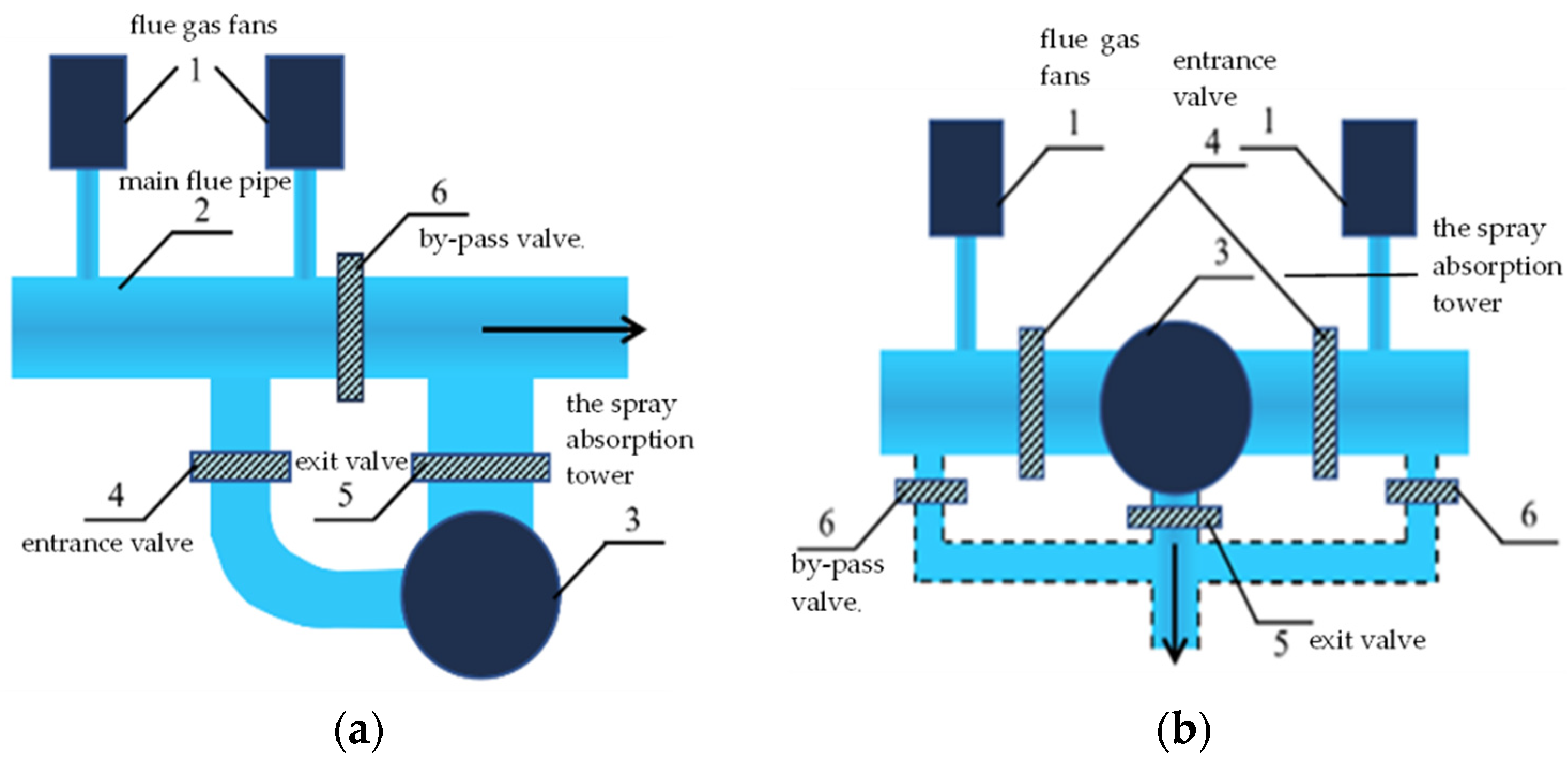
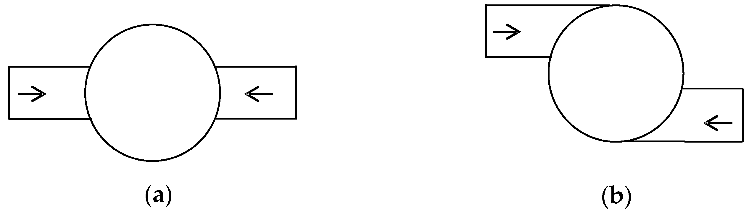
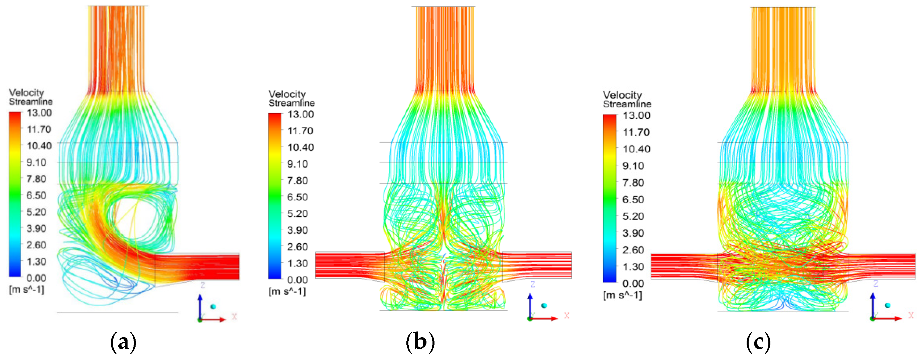
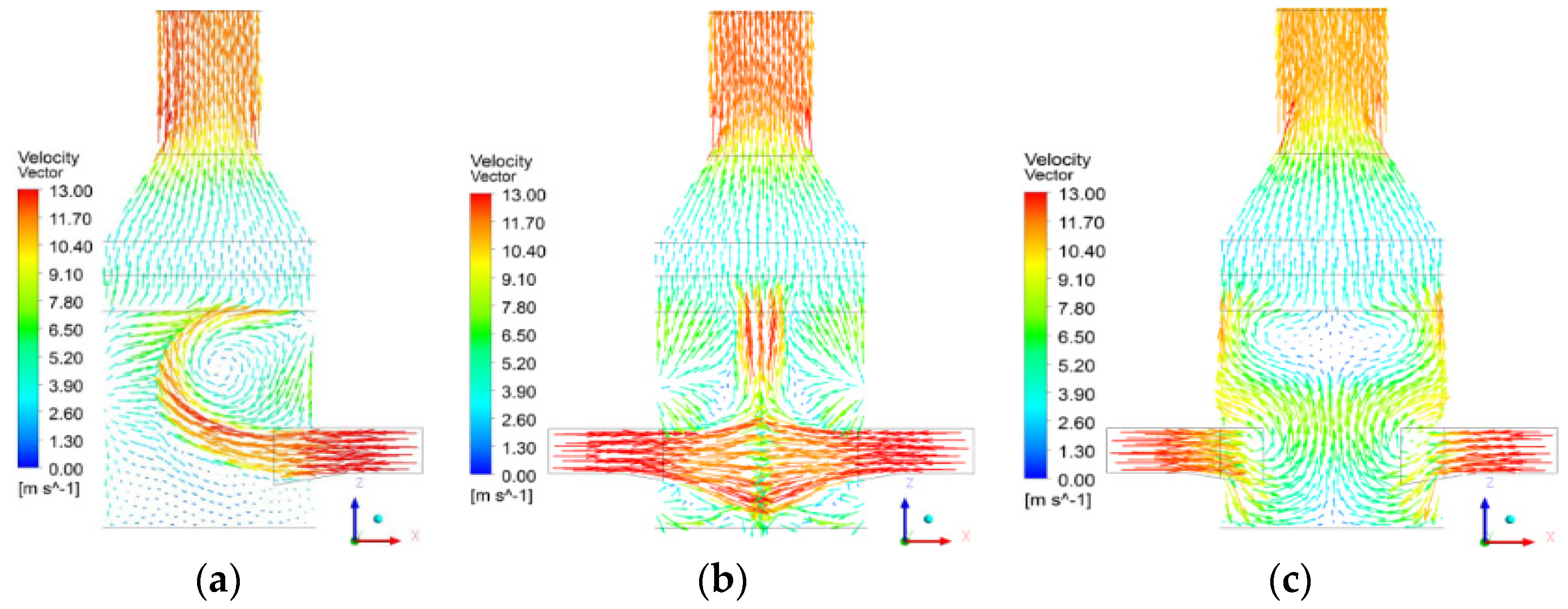
3.1. The Influence of Different Inlet Layouts

According to the general design of the flue gas desulfurization, the common layout is shown in Figure 2a: first, two sets of flue gas fans lead the exhaust gas into the main flue pipe and then enter the spray absorption tower with inlet and outlet, finally discharging the desulfurization flue gas to the chimney. This traditional design will cause a larger number of U-shaped bends between the outlet of the flue gas fan and the inlet of the absorption tower, resulting in a larger local resistance between the local flue pipes and high energy consumption. In contrast, the dual inlet design shown in Figure 2b can perfectly solve this problem, and the spray absorption tower is located between the two flue gas fans. The dual inlet design has two types of inlets, namely straight dual inlet and tangential dual inlet, the vertical view of which is shown in Figure 3.
The gas-phase streamlines and the gas velocity vector of the single inlet, straight dual inlet, and the tangential dual inlet without spray are shown in Figure 4 and Figure 5, respectively. From Figure 4 and Figure 5, it is found that there is a marked difference between the three layouts: Figure 4a and Figure 5a show that the high-speed flue gas habitually rushes to the opposite tower wall after entering the tower, a large whirlpool is formed near the inlet and the slurry surface in the single inlet tower; Figure 4b and Figure 5b show two high-speed flue gases entering the tower and oppose each other in the straight dual inlet tower, preventing each other from moving forward. The incoming flue gas flows upward, downward, left and right, and finally, two small vortices are formed near the inlet above the slurry surface; Figure 4c and Figure 5c show that in the tangential dual inlet tower, high-speed flue gases spiral up, which not only extends the running track of flue gas in the tower but also avoids the phenomenon that the flue gas is too dense locally at the middle which exists in Figure 4b and Figure 5b and makes the distribution of the flue gas uniform.
The gas velocity vector of the single inlet, straight dual inlet, and the tangential dual inlet with spray are shown in Figure 6. For the dual inlet tower, the flue gas velocity distribution is more uniform, and the phenomenon of flue gas rushing to the wall nearly disappears; on account of the strong interference of the downward spray droplets, two bigger gas flow whirlpools are formed on both sides of the inlet above the slurry surface, however, the whirlpools of the tangential inlet are smaller than those of the straight inlet, and as a result, the dual inlet design can reduce the possibility of byproduct depositing at the bottom of the inlet, and can enhance the stability of the system operation.
In contrast, the dual inlet design only changes the entrance pattern of the flue gas, however, it makes progress toward a remarkably uniform distribution, which enhances heat transfer and avoids byproduct deposition on the bottom of the inlet.

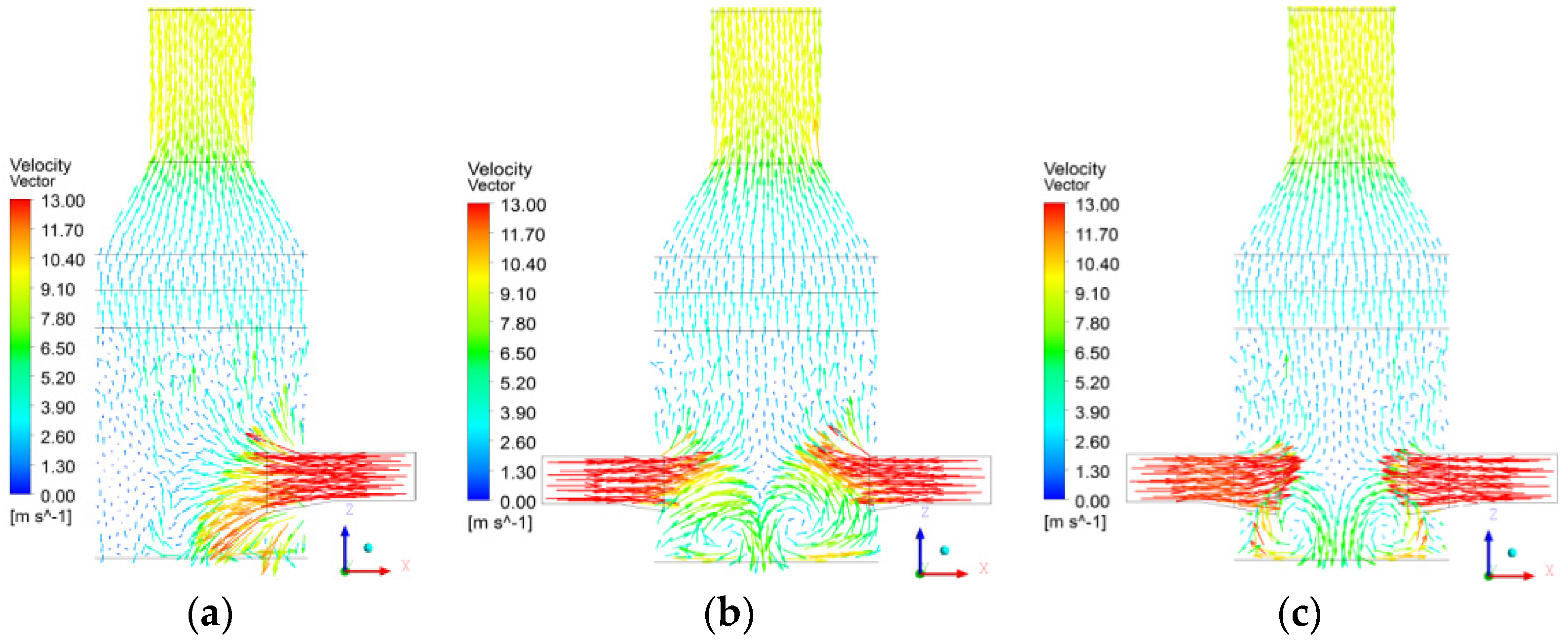
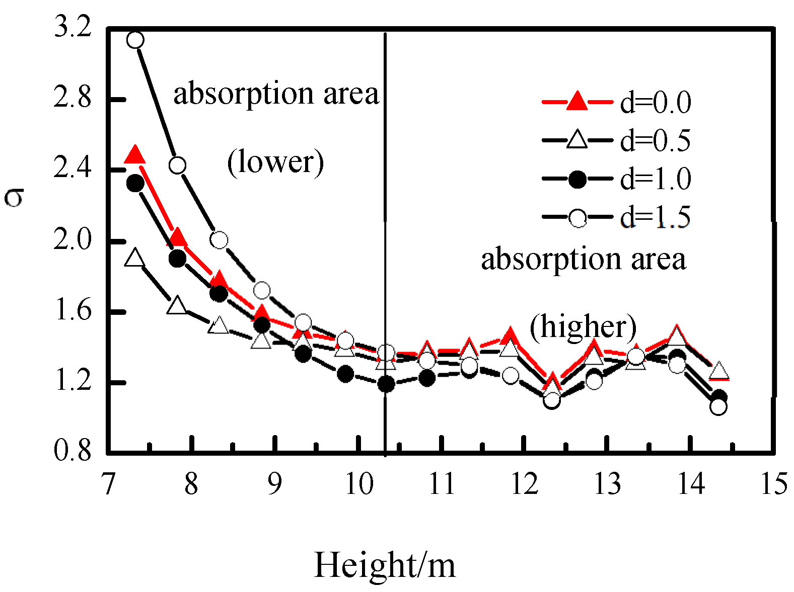
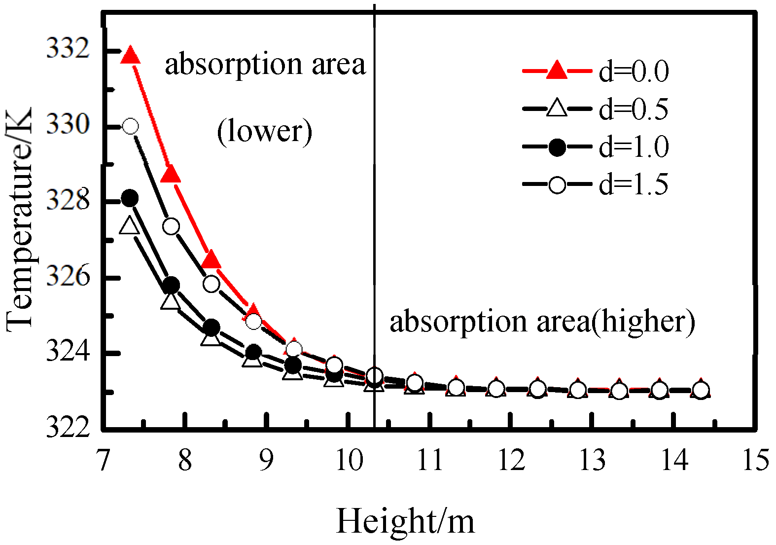
3.2. The Influence of Designed Flue Baffle at Inlet Area

As we know, the inlet section is always corroded by the sprayed slurry. If a flue baffle is placed in the inlet area, the baffle can block the spray slurry and guide the flow. The flow field with and without the flue baffle is mainly investigated, and the widths of the baffle are 0 m, 0.5 m, 1 m, and 1.5 m, respectively, as shown in Figure 1.
The gas-phase streamlines of the desulfurization tower with and without flue baffles are shown in Figure 7. It is seen that high-speed gas more easily flows to the center of the tower with baffles than that without baffles, meanwhile, there are few streamlines downward to the seriflux surface in Figure 7b, and as a result, the whirlpool becomes smaller and the intension decreases markedly at the bottom of the tower. All the results indicate that the flue baffle can help the flue gas avoid sticking to the wall, and thus the flow distribution in the absorption zone tends to be uniform.
Figure 8 shows the standard deviations of the representative section velocity [13] in the absorption area as a function of baffle width. The results indicate that when the baffle width ranges from 0.5~1.0 m, the gas flow distribution is uniform; on the contrary, if the baffle width is larger than 1.5 m, the velocity uniformity is worse than without the baffle. The desulfurization tower requires the flue gas to be distributed as uniformly as possible in different cross-sections. In theory, the uniform distribution has the advantages of long gas-liquid contact and mixing time, thereby improving desulfurization efficiency and reducing the desulfurized slurry required.
Figure 9 shows the average temperature of the absorption area as a function of the baffle width. The results show that due to the strong heat transfer between the flue gas and spray droplets, the gas temperature decreased rapidly, especially in the lower part of the absorption zone; the temperature in the lower part with baffles is lower than that without baffles. This shows that the additional baffles can promote heat transfer in the tower.
The pressure drop of the tower for different width baffles is shown in Table 2. It can be seen from the table that the pressure drop increases as the baffle width increases. The possible reasons are that due to the increase in the width of the flue gas baffle, the gas flow path will be extended, that is, the gas hold-up will increase, and then the density of the gas-liquid mixture and the frictional resistance will also increase.
Therefore, the baffles can improve the uniformity of the gas-liquid field, and can also lead to pressure increase, and at the same time, it is suggested that the baffle should be placed in consideration of the angle effect.

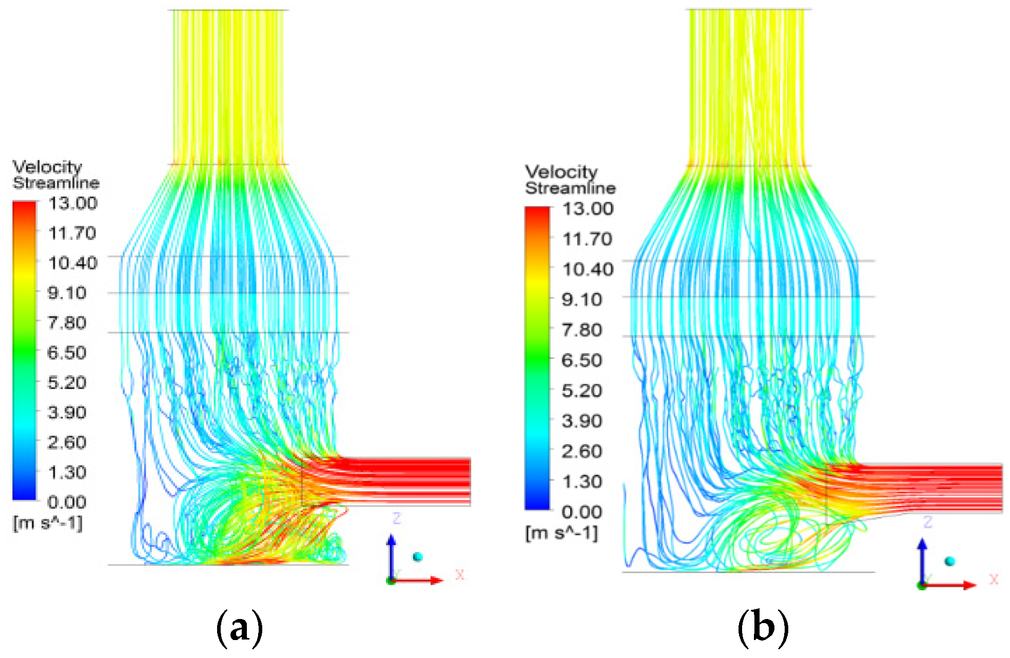
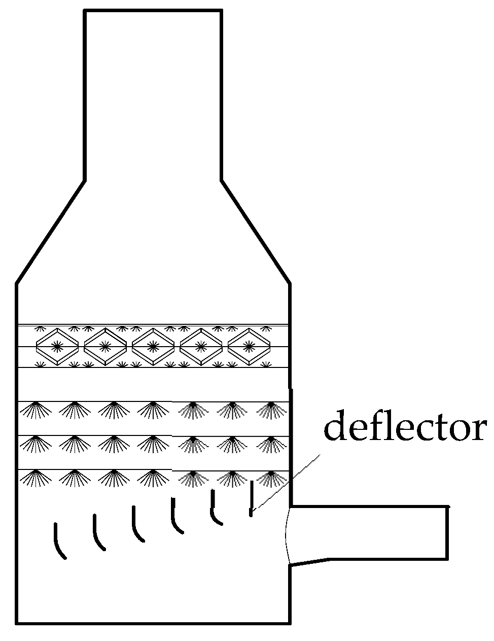
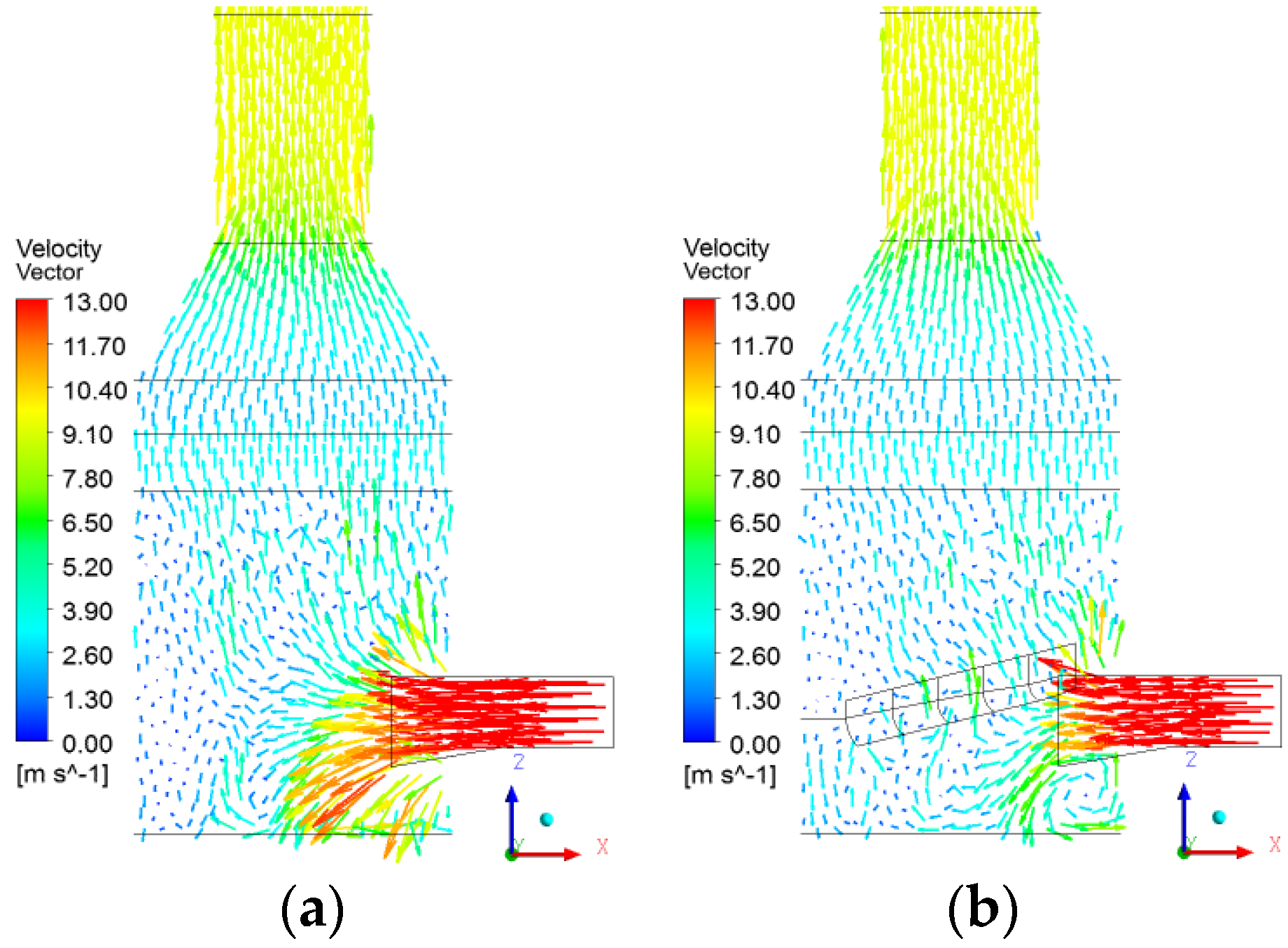
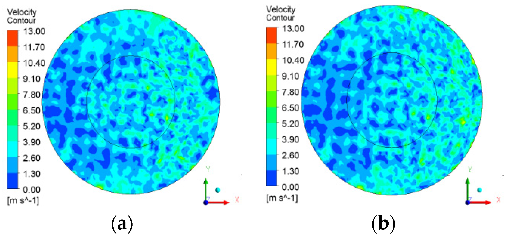
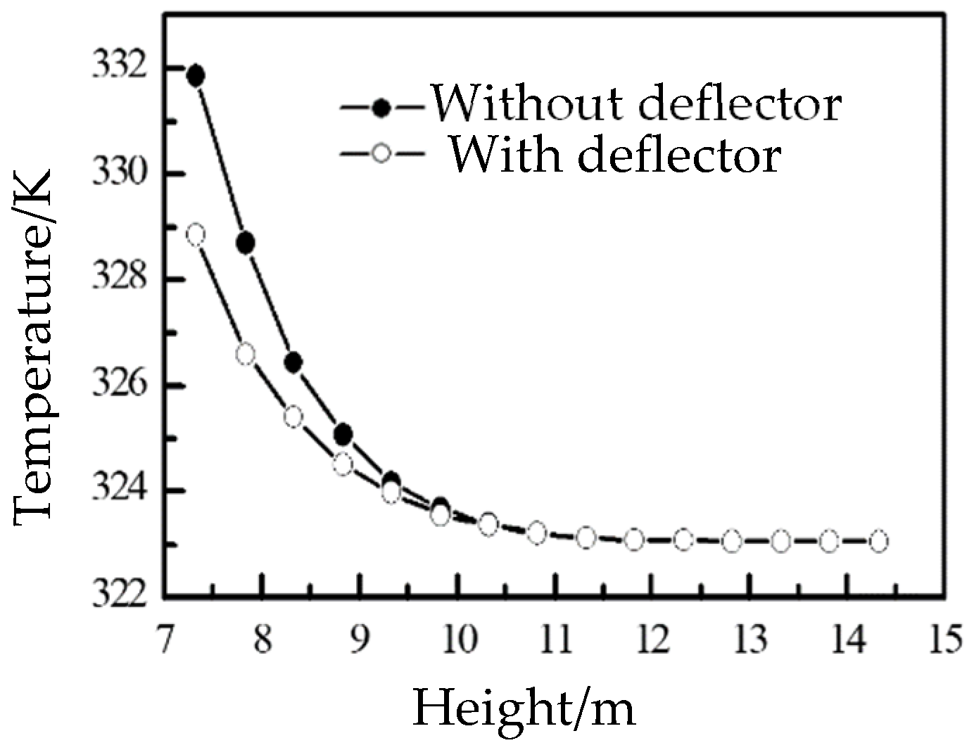
3.3. The Influence of Designed Deflector at Inlet Area

Normally, the flue gas inlet is located on one side of the absorption tower, and the flue gas enters the tower at a certain angle. Depending on its turbulent diffusion, inertia, and drop gravity, the gas flow distribution effect is limited, and the flow is still uneven, reducing the space utilization of the tower. The deflectors have been added to help optimize the flow uniformity. The schematic diagram of the installation of deflectors installed in the tower is shown in Figure 10.
The gas-phase velocity vector of the desulfurization tower with and withouta deflector is shown in Figure 11. The result shows that the flue gas under the deflector accelerates after hitting the deflector. Then, due to the entrainment of the high-speed stream, a counterflow zone is formed along the leeward side of the deflector. Therefore, the flue gas velocity distribution around the deflector is not uniform, and the area of the counterflow zone gradually decreases as the deflector is farther away from the inlet. However, it can be seen that the flue gas is distributed evenly in the area above the deflector.
Figure 12 shows the gas velocity contours of the cross-section at z = 1 m under the second spray layer. The standard deviation of the velocity is 1.36 with the deflector and 1.52 without the deflector. This means that adding a deflector is beneficial to the uniformity of the flow distribution in the absorption zone. The arc function designed at the bottom of the deflector can maintain the gas flow in a better direction and effectively reduce the influence of gas flow force on the deflector. Furthermore, the deflectors are distributed in a stepped order, which can also effectively reduce the energy loss of the gas crushing on the deflectors.
The average temperature of a representative section with and without a deflector is shown in Figure 13. The temperature quickly decreases after the high-temperature flue gas enters the tower, and the temperature of the absorption area changes greatly. The average temperature with a deflector is lower than that without a deflector, indicating that adding the deflector can promote heat transfer in the tower.

4. Conclusions

Based on a full-scale 3-D simulation of an ammonia-based WFGD tower in a sintering plant by using ANSYS CFX, the effect of structure on the gas-liquid two-phase flow field was investigated. From this study, the conclusions can be summarized as follows:
(a)
The flue gas distribution of the dual inlet tower is more uniform than that of the single inlet tower, and the mass and heat transfer effects are also better. In addition, the entrance of the dual inlet tower is not easy to deposit, which is conducive to safe operation. Moreover, the tangential dual inlet tower increases the residence time of the gas in the tower and avoids the frequent concentration of the gas in an area.
(b)
The designed baffle not only effectively blocks the entry of spray slurry, but also improves the flue gas distribution. According to engineering practice, flow field distribution, and pressure drop, the width of the baffle is preferably 0.5~1.0 m. At this time, it is recommended to install the baffle at a certain angle to prevent liquid from accumulating on the surface. The baffle, on the other hand, can make the flue gas flow toward the bottom of the tower first, increasing the flow path of the gas.
(c)
Adding a deflector with a simple structure, convenient operation, and stepped distribution in the inlet section can improve the uniformity of the flow field distribution and promote heat transfer and mass transfer, but there are also problems, such as the increased operating cost caused by the increased resistance, and this should be considered.

Author Contributions

L.L.: Conceptualization, Writing—Original Draft; B.Z.: Investigation; P.Z.: Writing—Review and Editing; L.Y.: Formal Analysis, Resources; M.L.: Data Curation; G.Z.: Supervision; H.W.: Writing—Review and Editing. All authors have read and agreed to the published version of the manuscript.

Funding

This research was funded by the State Grid Corporation of China (5200-202114093A-0-0-00).

Data Availability Statement

Not applicable.

Conflicts of Interest

The authors declare no conflict of interest.

References

  1. Zhang, Z.; Li, Y.; Lan, Y. Experimental study on fluid mechanics of nozzle and ammonia desulfurization of iron and steel sintering furnace. Adv. Mater. Res. 2013, 803, 363–366. [Google Scholar] [CrossRef]
  2. Fang, S.; Du, Y.; Huang, S.; Wen, W.; Liu, Y. Numerical simulation research for the optimization of the wet flue gas desulfurization tower. Appl. Mech. Mater. 2012, 170–173, 3662–3667. [Google Scholar] [CrossRef]
  3. Dong, Q.; Wang, C.; Peng, S.; Wang, Z.; Liu, C. A many-objective optimization for an eco-efficient flue gas desulfurization process using a surrogate-assisted evolutionary algorithm. Sustainability 2021, 13, 9015. [Google Scholar] [CrossRef]
  4. Li, X.; Dong, M.; Li, S.; Feng, Z.; Zhang, Z.; Li, W.; Ren, Y.; Lu, J. A numerical study of the ammonia desulfurization in the spray scattering tower. Chem. Eng. Process. 2020, 155, 1–12. [Google Scholar] [CrossRef]
  5. Gao, X.; Ding, H.; Du, Z.; Wu, Z.; Fang, M.; Luo, Z.; Cen, K. Gas-liquid absorption reaction between (NH4)2SO3 solution and SO2 for ammonia-based wet flue gas desulfurization. Appl. Energy 2010, 87, 2647–2651. [Google Scholar] [CrossRef]
  6. Jia, Y. Modeling and simulation of sulfur dioxide abatement with ammonia absorbent in the spray scrubber. Adv. Mater. Res. 2012, 599, 404–411. [Google Scholar] [CrossRef]
  7. Yan, J.; Bao, J.; Yang, L.; Fan, F.; Shen, X. The formation and removal characteristics of aerosols in ammonia-based wet flue gas desulfurization. J. Aerosol Sci. 2011, 42, 604–614. [Google Scholar] [CrossRef]
  8. Deng, Q.; Ran, J. Numerical study on flow field distribution regularities in wet gas desulfurization tower changing inlet gas/liquid feature parameters. J. Energy Resour. Technol. 2020, 143, 1–29. [Google Scholar] [CrossRef]
  9. Bai, H.; Biswas, P.; Keener, T.C. SO2 removal by NH3 gas injection: Effects of temperature and moisture content. Ind. Eng. Chem. Res. 1994, 33, 1231–1236. [Google Scholar] [CrossRef]
  10. Wang, S.; Zhang, Q.; Zhang, G.; Wang, Z.; Zhu, P. Effects of sintering flue gas properties on simultaneous removal of SO2 and NO by ammonia-Fe (II)EDTA absorption. J. Energy Inst. 2017, 90, 522–527. [Google Scholar] [CrossRef]
  11. Zhang, Q.; Wang, S.; Zhang, G.; Wang, Z.; Zhu, P. Effects of slurry properties on simultaneous removal of SO2 and NO by ammonia-Fe (II)EDTA absorption in sintering plants. J. Environ. 2016, 183, 1072–1078. [Google Scholar]
  12. Jia, Y.; Zhong, Q.; Fan, X.; Chen, Q.; Sun, H. Modeling of ammonia-based wet flue gas desulfurization in the spray scrubber. Korean J. Chem. Eng. 2011, 28, 1058–1064. [Google Scholar] [CrossRef]
  13. Wang, S.; Zhu, P.; Zhang, G.; Zhang, Q.; Wang, Z.; Zhao, L. Numerical simulation research of flow field in ammonia-based wet flue gas desulfurization tower. J. Energy Inst. 2015, 88, 284–291. [Google Scholar] [CrossRef]
  14. Zhang, Q.; Wang, S.; Zhu, P.; Wang, Z.; Zhang, G. Full-scale simulation of flow field in ammonia-based wet flue gas desulfurization double tower. J. Energy Inst. 2018, 91, 619–629. [Google Scholar] [CrossRef]
  15. Qu, J.; Qi, N.; Li, Z.; Zhang, K.; Wang, P.; Li, L. Mass transfer process intensification for SO2 absorption in a commercial-scale wet flue gas desulfurization scrubber. Chem. Eng. Process. 2021, 166, 108478. [Google Scholar] [CrossRef]
  16. Wang, P.; Dai, G. Field synergy of the rod bank on the enhancement of mass transfer in a spray column. Ind. Eng. Chem. Res. 2018, 57, 12531–12542. [Google Scholar] [CrossRef]
  17. Cui, L.; Lu, J.; Liu, L.; Qin, M.; Dong, Y. Simulation study on novel groove separator in a dual-loop wet flue gas desulfurization spray tower. Asia-Pac. J. Chem. Eng. 2020, 15, e2442. [Google Scholar] [CrossRef]
  18. Wang, P.; Zhuang, L.; Dai, G. Synergistic effect of droplet self-adjustment and rod bank internal on fluid distribution in a WFGD spray column. Chem. Eng. Sci. 2017, 162, 227–244. [Google Scholar] [CrossRef]
  19. Montanes, C.; Gomez-Samper, A.; Fueyo, N.; Ballesteros, J.C.; Gomez-Yague, P. Computational evaluation of wall rings in wet flue-gas desulfurization plants. Int. J. Energy Clean. Environ. 2009, 10, 15–36. [Google Scholar] [CrossRef]
  20. Chen, Z.; Wang, H.; Zhuo, J.; You, C. Experimental and numerical study on effects of deflectors on flow field distribution and desulfurization efficiency in spray towers. Fuel Process. Technol. 2017, 162, 1–12. [Google Scholar] [CrossRef]
  21. Tseng, C.; Li, C. Eulerian–Eulerian numerical simulation for a flue gas desulfurization tower with perforated sieve trays. Int. J. Heat Mass Tran. 2018, 116, 329–345. [Google Scholar] [CrossRef]
  22. Chen, Z.; Wang, H.; Zhuo, J.; You, C. Enhancement of mass transfer between flue gas and slurry in the wet flue gas desulfurization spray tower. Energy Fuels 2018, 32, 703–712. [Google Scholar] [CrossRef]
  23. Jin, Y.; Zhao, W.; Li, Z. Effect of gas-liquid contact intensification on heat and mass transfer in deflector and rod bank desulfurization spray tower. Processes 2021, 9, 1269. [Google Scholar] [CrossRef]
  24. Michalski, J.A. Aerodynamic characteristics of flue gas desulfurization spray towers-poly dispersity consideration. Ind. Eng. Chem. Res. 2000, 39, 3314–3324. [Google Scholar] [CrossRef]
  25. Marocco, L. Modeling of the fluid dynamics and SO2 absorption in a gas-liquid reactor. Chem. Eng. J. 2010, 162, 217–222. [Google Scholar] [CrossRef]
Figure 1. Diagrammatic sketch of the desulfurization spray tower; (a) tower structure; (b) flue gas inlet angle; (c) designed baffle in flue gas inlet. 1—seriflux level; 2—flue gas inlet; 3—the designed baffle; 4—first spray layer; 5—second spray layer; 6—third spray layer; 7—demist area; 8—flue gas outlet.
Energies 15 07771 g001
Figure 2. The layout of flue gas desulfurization tower; (a) Single inlet; (b) Dual inlet. 1—flue gas fans; 2—main flue pipe; 3—the spray absorption tower; 4—entrance valve; 5—exit valve; 6—by-pass valve.
Energies 15 07771 g002
Figure 3. Vertical view of tower with Dual inlet; (a) Straight dual inlet; (b) Tangential dual inlet.
Energies 15 07771 g003
Figure 4. The gas phase streamlines without spray; (a) Single inlet; (b) Straight dual inlet; (c) Tangential dual inlet.
Energies 15 07771 g004
Figure 5. The gas velocity vector diagram without spray; (a) Single inlet; (b) Straight dual inlet; (c) Tangential dual inlet.
Energies 15 07771 g005
Figure 6. The gas velocity vector diagram with spray; (a) Single inlet; (b) Straight dual inlet; (c) Tangential dual inlet.
Energies 15 07771 g006
Figure 7. The gas phase streamlines diagram with and without flue baffle; (a) d = 0 m; (b) d = 0.5 m.
Energies 15 07771 g007
Figure 8. Velocity standard deviations of the representative section.
Energies 15 07771 g008
Figure 9. Average temperature in representative section.
Energies 15 07771 g009
Figure 10. The schematic diagram of the installation of deflectors installed in the tower.
Energies 15 07771 g010
Figure 11. The gas velocity vector diagram with and without deflector; (a) Without deflector; (b) With deflector.
Energies 15 07771 g011
Figure 12. The gas velocity contours of cross-section at z = 1 m under the second spray layer. (a) Without deflector; (b) With deflector.
Energies 15 07771 g012
Figure 13. Average temperature of a representative section with and without deflector.
Energies 15 07771 g013
Table 1. Basic parameters of the numerical simulation.
ItemParameterValue
StructureTower diameter (m)14
Inlet size (m)11.08 × 3.13
Outlet diameter (m)7
Demist area height (m)2.5
Spray level gap (m)2
Inlet angle α (°)10
Designed inlet baffle wide (m)0, 0.5, 1.0, 1.5
Gas phaseInlet flue gas flow rate (m·s−1)13
Inlet flue gas dynamic viscosity (Pa·s)2.32 × 10⁻⁵
Inlet flue gas thermal conductivity (W·m−1·K−1)3.49 × 10⁻²
Inlet flue gas temperature (K)413
Inlet flue gas density (kg·m−3)1.131
Liquid phaseLiquid-to-gas ratio (m3/L)13
Seriflux dynamic viscosity (Pa·s)4.32 × 10⁻³
Seriflux thermal conductivity (W·m−1·K−1)0.67
Seriflux temperature (K)323
Seriflux density (kg·m−3)1310
Particle specified diameter (m)2 × 10⁻³
Spray nozzle angle (°)90
Particle injection velocity (m·s−1)6
Table 2. Drop of pressure between inlet and outlet.
Baffle Width d/(m)00.51.01.5
Drop of pressure ΔP/(Pa)743.78781.74796.85816.67
Publisher’s Note: MDPI stays neutral with regard to jurisdictional claims in published maps and institutional affiliations.

