1. Introduction
Urban air mobility (UAM) and urban air delivery (UAD) are safe, sustainable, affordable, and accessible means of transportation of people and goods, respectively, that will transform local and intraregional missions [
1]. This concept has gained ever-increasing interest and industry investments, with many aerospace manufacturers involved in the design, production, testing, and certification of new solutions for UAM and UAD. A comprehensive review of the literature sources related to urban air mobility can be found in [
2]. Thanks to UAM, advanced technologies and new operational procedures are expected to enable practical, cost-effective air travel in metropolitan areas in the forthcoming years.
Driven by the need to overcome the problem of increasing ground traffic congestion in urban areas [
3], UAM also focuses on the reduction in the carbon footprint. In fact, UAM transportation is generally realized in the form of electric and hybrid-electric vertical takeoff and landing vehicles (eVTOL/hVTOL), which are quieter and are associated with lower operating costs. The Vertical Flight Society has classified 600 different designs of eVTOL aircraft [
4] that integrate existing and emerging technologies, including distributed electric and hybrid-electric propulsion systems [
5]. Among the advantages associated with electric propulsion aviation [
6], Moore [
7] enumerates motor compactness, high efficiencies at both full and part load, no power lapse with altitude, insensitivity to air temperature, together with the already mentioned low noise, low operating costs, high reliability, and absence of local emissions. The current state of the art in terms of energy and power density of the battery, however, is not sufficient to sustain all-electric flight for UAM for long routes, as demonstrated in [
7]. To solve this problem, hybrid electric propulsion systems (HEPSs) have been proposed for UAM. A HEPS exploits the presence of two energy sources, usually a chemical storage unit (a fuel) and a battery and the corresponding energy converters. Note that this definition also includes hydrogen-powered vehicles where the chemical energy carrier is represented by the hydrogen vessel and a fuel cell is used as the energy converter instead of an internal combustion engine [
8].
UAVs with HEPSs can sustain longer route lengths and flight duration with respect to the all-electric counterpart, as pointed out in several works in the literature (see, for example, [
9,
10]). As a further advantage, in a hybrid electric UAM vehicle, takeoff and landing can be performed in electric mode to reduce the noise and the emissions of pollutants in urban areas [
11]. On the other hand, electrification calls for the need for improvement not only in batteries but also in motors, power converters, etc. [
12].
Studies on hybrid electric aircraft are mainly devoted to sizing (see, for example, [
13]) or to the energy management of HEPS (such as in [
14]). The energy flows in a vehicle for UAM are usually analyzed with a steady-state model applied to each flight phase (vertical climb, climb, cruise, etc.), but the transition between a flight condition and the following one cannot be captured by this modeling approach, as pointed out in [
15,
16]. Bianco et al. [
17] also emphasized how dynamic modeling is important in the development of electrified aircraft propulsion and advanced control techniques for unmanned vehicles for UAM, while conventionally, the dynamic behavior of a helicopter is linearized around some operating conditions [
18].
The dynamic response of the power system is quite critical in the case of rotorcraft. During its basic flight regimes (hover, climb, descent, and forward flight), the helicopter is not able to maintain a steady flight in the case of external disturbance, such as the action of a wind gust, so the pilot has to act continuously on the helicopter’s control [
19]. The fundamental control inputs of rotorcraft are the main rotor collective pitch, the lateral cycle pitch, the longitudinal cyclic pitch, and the second rotor collective pitch. The collective pitch control simultaneously changes the pitch angle of all the rotor blades and, therefore, the lift. To maintain a constant rotor rpm, a proportional alteration in power is required to compensate for the drag change caused by the variation of the pitch angle [
19]. In fact, the engine speed for a helicopter must be held in a range ±2.5% of its nominal values for safety reasons [
20]. To this scope, a correlator is used in piston engines while a governor is adopted in turbine helicopters, such as that considered in this investigation. The governor senses the shaft RPM and adjusts the throttle of the engine to regulate the rotor rpm. If these devices are not installed, the throttle must be moved manually, and, in this case, the failure of the pilot to hold the rotor-motor chain is the cause of crashes. The engine governor is implemented as a single-loop feedback control system that measures the engine regime. This topic was extensively addressed in the scientific literature in the 1980s [
21] and is nowadays an established technology, even if the problem of rotorcraft stability has received new study in the last decade because of the development of remotely controlled rotorcraft (see [
22,
23]). However, the action of the governor depends on the dynamic response of the powertrain, which can be quite different in a hybrid electric power system with respect to a conventional turboshaft engine or a full electric configuration, so it is important to address this topic.
The role of hybridization in supporting the engine during transients has only been hinted at in the scientific literature. Wortmann et al. [
24] pointed out that electric motors can produce their torque within a few milliseconds, while gas turbine engines produce their torque within a split of a second. Bianco et al. underlined that the slow response of the turboshaft engine is due to the operational and safety limits that must be satisfied by the engine controller in [
14].
The dynamic of a turbine engine is addressed in some works in the literature [
25,
26] but, to the authors’ knowledge, only a few of them analyze the dynamic behavior of the whole hybrid electric system, and only one considers a parallel HEPS with a turboshaft for rotorcraft application. Wortmann et al. [
24], in fact, performed a comparison in terms of acceleration time from low thrust to full power by keeping the speed of the engine constant. In fact, the investigation by Wortmann et al. refers to turbojet engines where there is no mechanical production of the thrust. In [
17], a parallel configuration with two single-spool turboshaft engines and an electric machine is considered. The rotor’s dynamics are not modeled in detail, and their revolutionary speed is considered constant. This is achieved by a torque-sharing controller that determines a speed setpoint bias applied to the turboshaft engine producing the lesser torque. This coordination action does not take advantage of the already cited better transient characteristics of the electric machine.
The dynamic of a hybrid-electric multi-copter is analyzed by Bouchard et al. [
27] but for a series configuration where the rotors are mechanically connected to electric motors, and one of them is used as a master to regulate the angular velocity. The model was mainly developed to analyze the dynamic behavior of the system in the case of faults.
The investigation of Roumeliotis et al. [
28] analyzes the performance of a recuperated gas turbine in a hybrid electric configuration and puts into evidence the possibility of using an electric drive to compensate for the delay of the turbine engine in providing the required torques thanks to the small time-constants of the electric system. However, this effect is addressed only qualitatively in the work by Roumeliotis et al., and this lack of detailed analysis gave the authors of the present investigation the idea of analyzing this aspect in a HEPS for a coaxial-rotors rotorcraft developed in the framework of the SMEA project of the Aerospace technology district. The SMEA project is aimed at developing health monitoring tools for conventional and hybrid electric power systems.
In the present study, the dynamic behavior of the parallel hybrid coaxial rotorcraft is evaluated with a forward modeling approach that takes a sequence of pilot commands and operating conditions as input and analyzes the transition between the typical flight regimes of the rotorcraft (from hover to high-speed forward flight). The entire propulsive system, together with the rotors, has been modeled with a dynamic approach paying particular attention to the turboshaft engine. Moreover, this investigation proposes and tests a coordination method that achieves torque-sharing control by exploiting the faster dynamic response of electric machines. Such coordination has been previously discussed by the authors in [
29], with a simplified version of the model in response to an arbitrary power request discontinuity, while in the present investigation, complete system analysis is performed, including rotor dynamics. This aspect, together with more accurate implementation of powertrain controls and low pressure (LP) spool dynamics, represents the element of novelty of the proposed work with respect to the literature and past works of the authors.
The paper is organized as follows.
Section 2 describes the specification of the hybrid electric UAM vehicle, including the energy management strategy.
Section 3 explains the modeling approach, while
Section 4 reports the results of the investigation that are discussed in
Section 5.
2. The Hybrid Electric Air-Taxi
The configuration considered here for the UAM application is a coaxial-rotor helicopter that uses two main rotors mounted one above the other on coaxial rotor shafts. Such a configuration is making a comeback in recent years because of its higher flight speed capability, payload capacity, and maneuverability [
30]. Though its performances are still unclear and debated amongst the research community, the advantage deriving from the elimination of the tail rotor and its transmission [
31] is undisputed. In fact, the torque balance is achieved thanks to the adoption of the second counter-rotating rotor.
In the context of HEPS, several configurations are possible, including series hybrid, parallel hybrid, and turbo-electric, according to the electric or mechanical sum of the power derived from the two energy sources. These configurations are compared in detail in [
32], where Finger et al. proved the higher performance of the parallel hybrid configuration with respect to the series configuration if no aerodynamic enhancement of the vehicle is assumed [
33]. Further, the disadvantages related to the series-hybrid scheme are reported in [
34], where different hybridization schemes have been compared using typical mission profiles for the analysis.
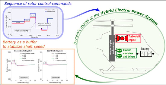
In this investigation, a parallel HEPS (
Figure 1) with a hybridization degree of 0.45 (ratio of electric power to total installed power) is considered [
35]. A turboshaft engine and two electric motors are mechanically connected to the rotor shaft through a gearbox. The electric machines are fed by a lithium-ion battery sized to ensure electric backup operation [
34] with a specific electric-backup mission that differs from the operating conditions considered in this investigation. Therefore, the safety issue will not be considered in the present investigation. The details of the machines and of the battery are not reported for the sake of confidentiality.
With respect to a conventional power system, hybridization allows the engine working point to be controlled, thus reducing low-efficiency operating points. Moreover, the presence of the electric machine is also a beneficial aspect in terms of flight safety since the battery and the electric motors would also allow mission completion in the case of engine failure occurrence, whilst such an event could jeopardize the mission if it happened on a single-engine vehicle. Finally, hybridization avoids the presence of an additional starter engine, such as that used in a traditional turboshaft engine, to drive the engine shaft to the desired speed. Only after the engine reaches a predetermined speed, fuel is supplied to the engine, and the ignition starts.
Since the energy management strategy (EMS) of the multi-source operation is a critical feature in HEPS, this aspect has been investigated by some of the authors in previous works. In particular, the optimal curve for the discharge of the battery along the mission was found with the application of the Dynamic Programming Method [
14]. For the same reference vehicle, a fuzzy logic energy management strategy was also defined in [
14].
In this investigation, the torque split ratio will be arbitrarily defined, and a sensitivity study will be performed. The torque split ratio is defined as:
where
is the torque to be delivered by the electric machines according to the energy management strategy, and
is the torque required by the rotor.
In fact, while previously mentioned works from the same authors are aimed at developing and optimizing energy management strategies to meet the goals of fuel consumption minimization and electric backup preservation, here, the focus is set on the dynamic performance improvement that can be achieved, for a fixed power split, through the activation of a coordination block. This can be defined as an electronic device designed to act in the case of disturbing actions (pilot commands or wind gusts) that generate a difference between the engine required power and the engine actual power output and to adjust the torque split consequently. Since such deviation is mainly due to response lag of the engine (as explained in [
27]), electric motors are used here to reach the equilibrium at the desired speed in a faster way. The action of the coordination block can be expressed as follows:
where Q
ICE and Q
EM represent the actual torques of the engine and the electric motors, respectively, and the subscript req refers to the set points decided by the EMS.
Two cases are compared in this investigation, with and without the coordination block. In the first case, the torque split defined by the EMS is kept unchanged while, in the second case, the value of is dynamically adjusted according to Equation (2) with the goal of minimizing the deviations of the rotor’s speed from the nominal value. Such a goal is achieved by setting a PID controller, as demonstrated later.
3. Modeling Approach and Controls
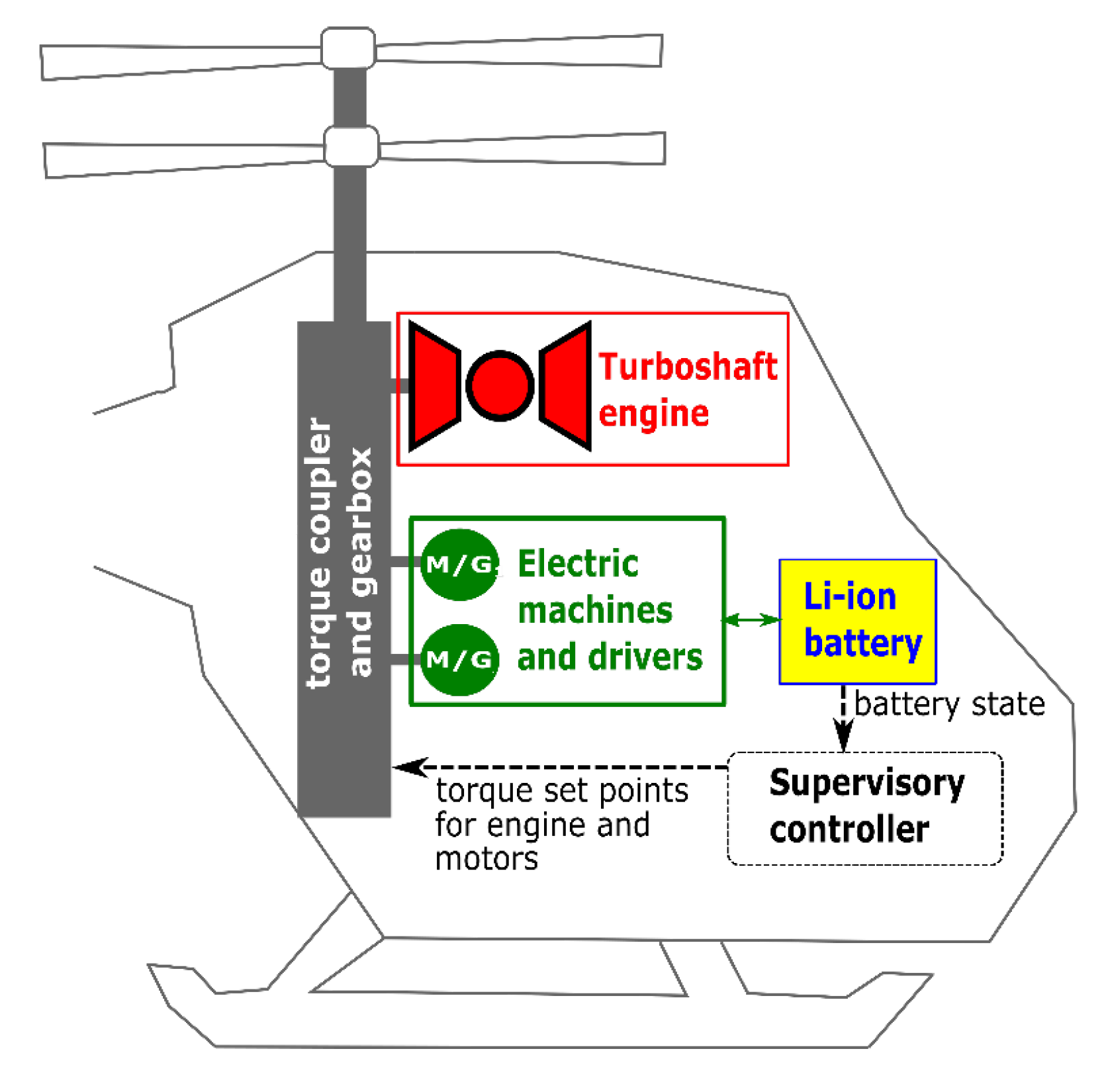
To compare the two cases, a dynamic model of the hybrid rotorcraft was developed and implemented in the Matlab/Simulink environment. It consists of several interconnected blocks (as shown in
Figure 2) that solve a set of algebraic and differential equations with a fixed-step time (10 ms) Bogacki–Shampine method (ode3) [
36].
The model takes, as inputs, the rotor control signals
, , , , ) and the speed components of the rotorcraft (
, ) and calculates the rotor speed
and the main working parameters of each component of the powertrain, the fuel flow rate, and the battery state of charge. The engine and the motors are connected to the rotor shaft through a clutch to decouple them in the case of thermal only or all-electric behavior, respectively, or in the case of failure. Moreover, brakes are used to slow down the rotor during shutdowns [
17]. These components are not modeled because they are not relevant to the present investigation. Moreover, their dynamic is much faster than the dynamic of the engine and the battery.
3.1. The Rotor Dynamics
The rotor dynamics block models a couple of coaxial counter-rotating rotors. Since the lower rotor partially works in the wake of the upper one, accordingly to their axial spacing, this requires adjusting the rotors to a different collective pitch angle if yaw trim must be achieved [
30]. Thus, for each flight condition, the collective pitch angles
and
of the upper and lower rotors are obtained by subtracting and summing an amount
to a common value of initial collective pitch
, respectively. Both rotors have the same characteristics, which are reported in
Table 1, and the axial spacing is assumed to be equal to 1 m. Starting from the inputs of the overall model, the rotor torque calculation is carried out as proposed in the literature in [
21,
37], i.e., with the Blade Element Momentum Theory. The blade elemental forces are integrated along the useful radius (net of tip and root cut out losses) with the assumption of uniform inflow, which requires an iterative procedure to calculate rotor forces and moments as a function of inflow ratio and then update inflow estimation. Flapping dynamics are taken into account too, with the assumption of a rigid blade and uncoupled pitch and flap motion. Note that the details of the rotors model, which was developed by Avio Aero, cannot be reported because of confidentiality issues. The gearbox is simulated, in the present investigation, with a quasistatic approach, so the torque and speed of the rotors are simply corrected by the gear ratio to obtain the torque and speed at the main shaft. It should be noted that both thermal and electric power sources are considered as always connected to the rotor shaft in the simulations performed in this work.
The rotor speed is calculated by the balance implemented in the shaft dynamics block:
where
Np is the shaft speed (proportional to the rotor speed
through the gear ratio
),
is the overall moment of inertia of the components connected to the shaft, while
,
, and
are the torques of the engine, load, and electric machines, respectively. At this point, after the integration of Equation (3), the value of the shaft speed is updated at each iteration, and the deviation from the nominal value is calculated. Such speed error is given to a PID controller as input, which gives a torque correction as output so as to stabilize the shaft speed. The shaft balance block is depicted in
Figure 3. The parameters of the PID controller were identified with a trial-and-error approach. A sensitivity analysis of the effect of the PID parameters on the dynamic response of the system is reported in
Section 4.3.
As pointed out in [
27], spool dynamics are critical for stationary and transient analysis because it captures the interactions among the power-consuming and producing gas turbine components on a spool. The typical value of the time constant for spool dynamics reported in the literature is about one second for turboshaft engines.
3.2. The Energy Management Block
The load torque is the main input of the energy management block that implements the logic explained below and calculated the setpoints for the engine and the motors. The setpoints are then corrected in the coordination block, which has the goal of correcting the electric motor’s torque request to counterbalance the slow dynamics of the engine.
3.3. The Engine Model
The engine considered in this investigation is a two-spool turboshaft engine simulated with the sub-model reported in
Figure 2 and detailed in
Figure 3. The high-pressure turbine (HPT) is connected to the compressor and rotates at speed
, while the low-pressure turbine (LPT) is connected to the rotor shaft and rotates at
. A zero-dimensional approach is employed in modeling engine components, i.e., the flow properties are averaged at the inlet and exit sections of each sub-component [
38], namely the inlet, the compressor, the burner, and the two turbines. As explained in detail later, the three most important dynamics of a turboshaft engine are included in the model:
- -
The balance of work between the components on the compressor shaft.
- -
The volume dynamics, i.e., the accumulation of gas mass inside the cavities between adjacent components.
- -
The delay in the fuel flow rate provided by the fuel control system.
Heat transfer between a component’s material and the flow going through the component during operation and tip clearance effects are neglected in this work, as also in [
27].
The thermodynamic processes throughout the engine are represented with the station numbers 1–6 in
Figure 4.
The inlet (stations 1–2) is modeled as a ram-air element with a constant efficiency (
ηr = 0.9) so that the actual pressure rise realized in the inlet is:
However, due to the low airspeeds of the air-taxi rotorcraft, this effect is quite negligible.
The compressor (stations 2–3) and the two turbines (stations 4–5 and 5–6 for HPT and LPT, respectively) are represented as gas-path components, where the values of the output streams (total pressure, temperature, density, and mass flow) are calculated from their current state and values of the input streams according to their performance maps. The efficiency maps of the compressor and the two turbines were obtained with the procedure explained in [
39].
In particular, the compressor map is used to obtain the corrected mass flow rate and isentropic efficiency
as a function of the corrected rotational speed and the pressure ratio
. The core speed is mapped as a function of power request. Once obtained
from the map, compressor exit temperature
is calculated as:
In turn, is calculated iteratively from the burner exit pressure.
The burner’s (stations 3–4) dynamics are represented by its temperature, which is calculated with an energy balance using the fuel flow rate (FFR) as input:
where
is the combustion efficiency,
is the lower heating value, and
the air-fuel ratio.
is averaged among air and burned gas values of constant pressure specific heat, which, in turn, are polynomial functions of the temperature. The pressure drop across the combustion chamber is assumed to be equal to 2% of the input stream pressure.
The simulation of the mass balance is performed with the inter-component volume (ICV) method, as applied in [
40]. The dynamics of the fluid pressure in the ICV volumes A and B of
Figure 4 can be written as:
where the variation in mass is due to the difference between the mass flows going into (
) and out (
) of the volume during transients, while it is zero in stationary conditions. In Equation (7),
and
are the pressure and temperature in the ICV at each time step,
is the volume, and
the elastic constant of the gas (universal gas constant divided by the molecular mass of the gas).
The same procedure is applied to HPT, with an inter-component volume between the two turbine modules, which gives HPT exit pressure and thus allows the flow rate and efficiency
to be obtained from the corresponding maps given
and, consequently,
Instead, LPT exit pressure is calculated as a function of fuel flow rate, with a correction to account for altitude effects.
The balance of the work between the components on the compressor shaft can be written as:
where
is the moment of inertia of the compressor shaft, and
and
are the instantaneous power of the high-pressure turbine and the compressor.
The fuel system dynamics are modeled through a first-order system, with a time constant
, as in the GSP reference turboshaft model [
41]. In fact, the whole stand-alone turboshaft engine developed in Simulink had been previously validated by the authors in comparison with the analogous GSP reference model [
42].
3.4. The Electric Motor
The electric motor block distributes the electric torque request equally among the available electric machines. Each motor is modeled with the Simulink “Mapped Motor block” that implements mapped motor and drive electronics operating in torque control mode.
The output torque tracks the torque reference demand and includes a motor-response and drive-response time constant. The block assumes that the speed fluctuations due to mechanical load do not affect the motor torque tracking. The efficiency of the machine/drive block is mapped as a function of the required torque only (being the shaft speed almost constant in all cases), as reported in
Table 2.
3.5. The Battery Block
As for the battery block, the model has been developed in-house and consists of three sub-models, as clarified in
Figure 5.
The voltage calculator determines the voltage of the battery
as:
where
is the battery current and
is the open-circuit voltage mapped as a function of the battery state of charge SOC. The internal resistance
can be upgraded in the aging sub-block according to the battery cycle number (i.e., the number of complete discharge/charge cycles performed on the battery) using a model previously developed in [
43] and obtained by fitting the experimental data reported in [
44].
The SOC estimator implements a modified version of the coulomb counting method that includes the Peukert effect. The model calculates the corrected current
as in Equation (11), where
is the current at which the nominal capacity of the battery is referred to (usually 1C) [
45].
The battery dynamic is expressed by the rate of variation of the State of Charge
Note that in Equations (11) and (12), both the battery capacity
and the Peukert coefficient
are dependent on the battery age (
Figure 5) and can be updated in the aging sub-block. For the validation of the battery model with experimental data, please refer to [
43].
3.6. Validation Issues
The lack of experimental data in the literature about hybrid electric power systems for rotorcraft makes it impossible to perform a full validation. Nevertheless, the proposed model can be considered valid because the stand-alone models of the engine and the battery were validated in previous works. In particular, ref. [
42] compares the dynamic behavior of the stand-alone turboshaft engine with the results of the same engine modeled in GSP, while investigation [
43] details the validation of the battery model. A sensitivity study will be proposed for the parameters that were arbitrarily chosen by the authors in the range suggested by the GSP simulation package [
38] since it is quite impossible to find experimental data for the validation.
4. Results
The modeling approach described in the previous section was applied to a sequence of the following flight phases: hover, low-speed climb, high-speed climb, low-speed forward flight, medium-speed forward flight, and high-speed forward flight of arbitrary duration.
Each of them was simulated at sea-level conditions. The torque split ratio
was varied between 0 (thermal mode) and 1 (all electric). However, the entire mission cannot be performed with a
, unless on-board battery charging is provided since, in these cases, the battery gets fully discharged and the simulation is aborted. Though not complete, these simulations have been included in the plot for a comparison of the dynamic behavior of the hybrid electric power system. The transition from one phase to the following one is supposed to take place in a time interval of three seconds. The resulting collective pitch command is depicted in
Figure 6, as well as the entire sequences of all input commands.
Each flight phase is characterized by the torque demand depicted in
Figure 7, which is split into the thermal engine torque request and electric motors torque request accordingly to the value of
defined by the EMS.
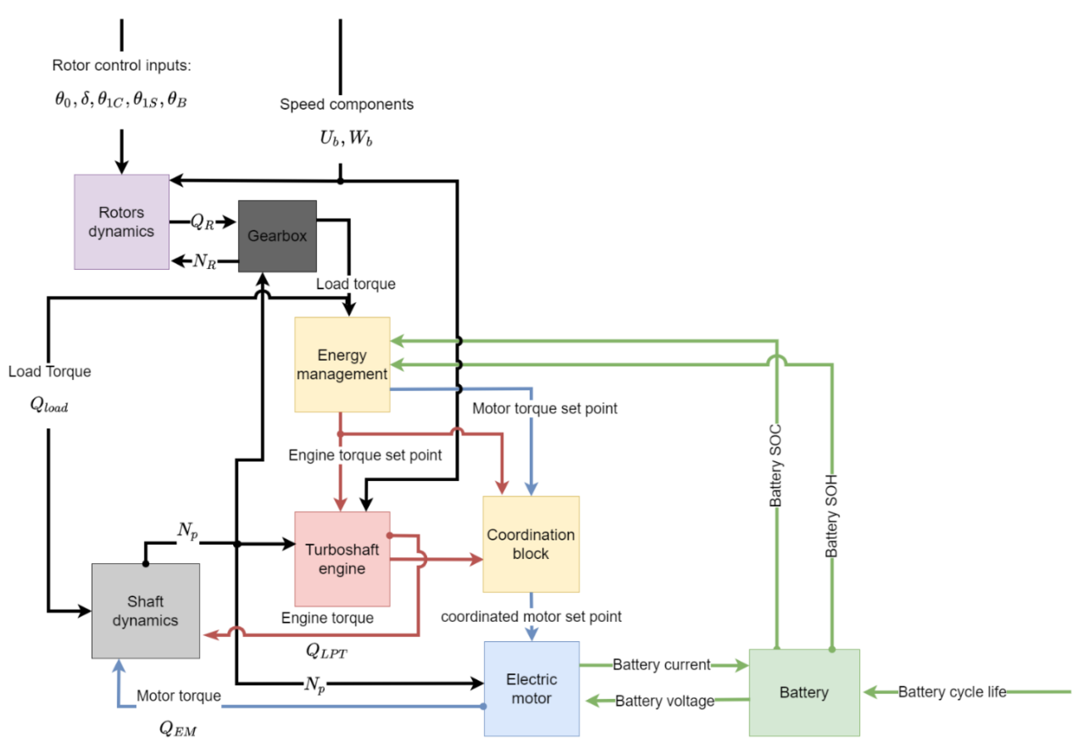
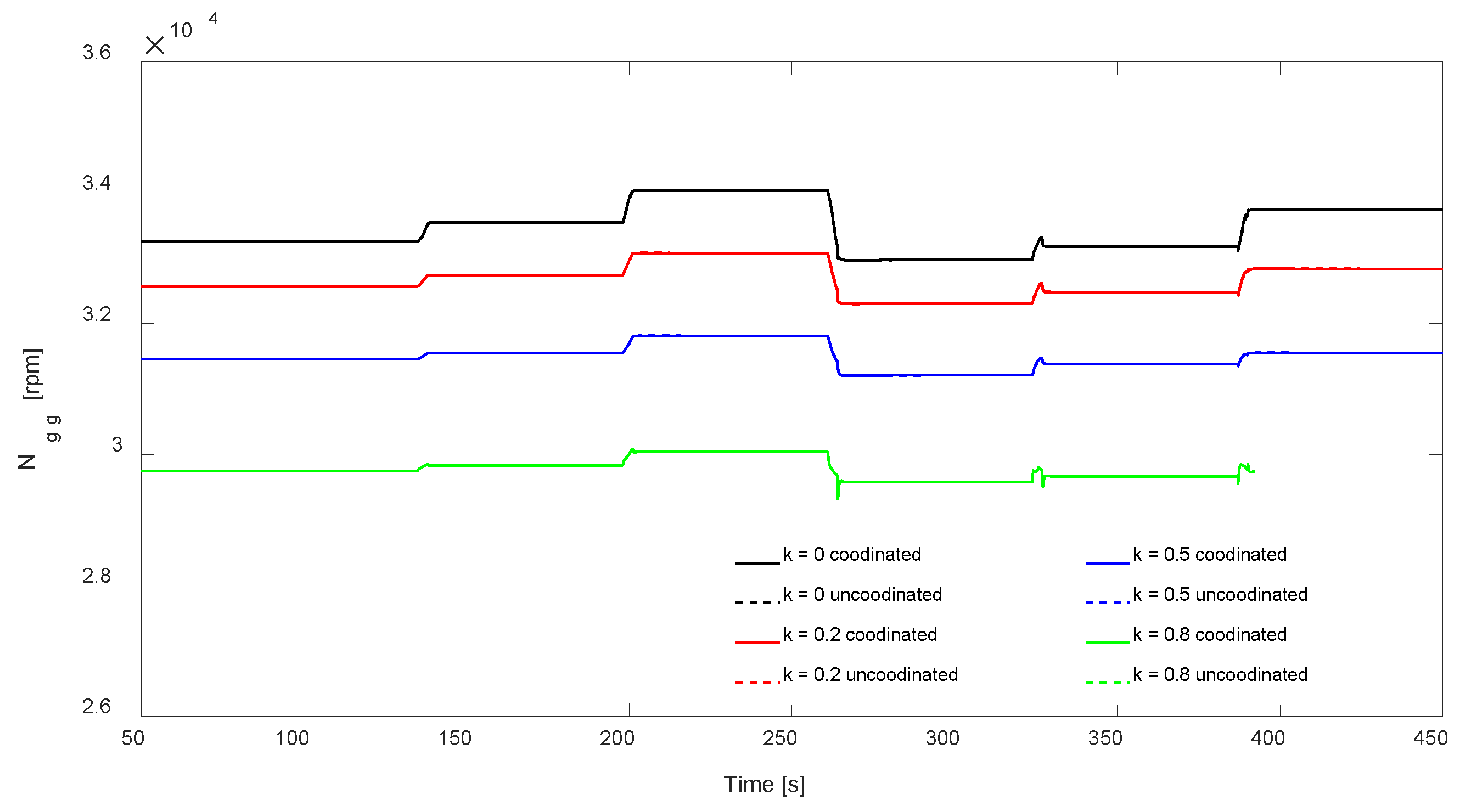
Figure 8 shows the LP spool speed with different values of
, with both the coordination block activated and deactivated, around each transient phase (labeled #1, #2 etc., in
Figure 7). Transient #1 has been neglected because its effect resulted in being quite negligible on the system. From the plots of
Figure 8, it can be noted that, without coordination, shaft speed stability increases with increasing involvement of the electric machines: the highest oscillations during transients are associated with the pure thermal configuration, while the lowest deviations from nominal speed are obtained in electric mode. The activation of the coordination block alters this trend: lower values of
correspond to a higher load on the turboshaft engine, and the electric torque correction determined by the coordination block is slightly higher in such cases.
Figure 9 underlines the effect of coordination on each transition previously defined. Generally speaking, the system with coordination appears to be more stable than the uncoordinated one in all cases, and the differences due to the hybridization degree are negligible. On average, the role of coordination fades away in about 6 s.
From the plots above, it is evident that the most critical transient is #3. For this reason, transient #3 has been chosen for quantitative analysis by calculating the overshoot and settling time of the shaft speed (see
Table 3). Note that the settling time has been calculated as the time required for the shaft speed error to fall in a range ± 0.1% since the oscillations of the speed are quite limited in all cases.
The values reported in
Table 3 shows how the increasing recourse to electric motors in power generation is generally beneficial in stabilizing the system behavior. In fact, both overshoot and settling time decreases with increasing
For the coordinated system, the overshoots and the settling times are quite low for all values of electric contribution, proving the effectiveness of the coordination action.
4.1. Effect on the Battery Current and State of Charge
The effect of additional torque request on electric motors due to coordination is visible on battery current draw during transients, as depicted in
Figure 10. Note that in the case of
, the EMS selects a thermal operation mode where the battery is not used while the coordination block makes use of the battery only to stabilize the rotor shaft speed.
The coordination effect determines a peak current in each transient, which is more evident when the electric contribution is low () but never exceeds the maximum c-rate of the battery. The overall effect on the state of charge is negligible; the maximum difference between the final state of charge with and without coordination is 0.3% and is obtained in the case of (thermal mode).
Figure 11 shows the impact of the selected power split and coordination on battery SOC along the simulated sequence. As is obvious, battery discharge is strongly related to the selected value of
to the extent that power splits higher than 0.8 cause the battery to fully discharge before the end of the simulation. The effect of coordination is not discernible since battery SoC for the coordinated and uncoordinated systems appear overlapped. In fact, as can be seen in
Figure 11, the difference in battery current during transient phases is too small and of short duration to determine a more tangible difference in overall battery discharge.
4.2. Effect on Fuel Flow Rate and Compressor Speed
Figure 12 shows the compressor speed related to each power split level: apart from the different operating regimes associated with each load condition, being the gas generator speed mapped as a function of engine torque request and actual LP shaft speed, in this case, a slight difference between the coordinated system and the uncoordinated one is recognizable. Though, also in this case, the difference between the two cases for a fixed value of
is negligible and vanishes during steady-state operation; the same trend characterizes fuel flow rate, as shown in
Figure 13.
We can conclude that the major effect of coordination activation is on the electric machines only and, most importantly, on the rotor speed stabilization, which is the purpose it was designed for.
4.3. Sensitivity Analysis
In the present investigation, the shaft inertia of the LP spool shaft has been arbitrarily assumed, starting from a value of inertia taken from the reference GSP turboshaft model. A plausible value of inertia for the electric drive was assumed on the basis of the data in [
46], where an electric motor with the same rated power is described. As previously mentioned, however, such value only has an approximate significance, which should be investigated deeper with a proper design of the coupling devices if a more accurate estimation is needed.
To address this issue, a sensitivity analysis of the influence of shaft inertia has been performed in this investigation by increasing the overall inertia
up to a factor of 10. The results are shown in
Figure 14.
Note that lower inertia cases are characterized by a higher amplitude of speed oscillation, but they achieve a steady condition faster than those with a high value of shaft inertia, which, in turn, display smaller deviations but in a longer time interval. When the coordination is enabled, differences in dynamic behavior due to system inertia are canceled by the beneficial effect of the coordination block so that shaft speed follows its nominal value tightly during each transition from one flight phase to another.
Table 4 gives the values of shaft speed overshoot and settling time corresponding to the third transient phase of
Figure 14, for the system working in thermal mode (
). The stabilizing effect of the coordination is evident. In fact, the speed oscillation amplitude is restricted by the activation of the coordination block, which, in turn, determines a shorter settling time.
As mentioned earlier, the parameters of the PID controller that determines the torque coordination were found with a trial-and-error approach. A sensitivity analysis was performed by varying the P, I, and D parameters according to the values reported in
Table 5. The results are reported in
Table 6 and show how the overshoot and the settling time in the case of
are only slightly affected by small variations of the PID parameters.


