Article

Comparative Performance Assessment of Different Energy Storage Devices in Combined LFC and AVR Analysis of Multi-Area Power System

1
Department of Electrical and Electronics Engineering, Vasireddy Venkatadri Institute of Technology, Guntur 522508, India
2
Department of Electrical and Electronics Engineering, Anurag College of Engineering, Ghatkesar 501301, Telangana, India
3
Department of Electrical and Electronics Engineering, Malla Reddy Engineering College (A), Maisammaguda, Secunderabad 500100, Telangana, India
4
Department of Electrical and Electronics Engineering, National Institute of Technology, Delhi 110040, India
5
Department of Electrical Engineering, I. K. Gujral Punjab Technical University, Jalandhar 144603, India
6
School of Electrical and Electronic Engineering, University College Dublin, D04 V1W8 Dublin, Ireland
7
Department of Electrical and Computer Systems Engineering, Monash University, Clayton, VIC 3800, Australia
8
Department of Management & Innovation Systems, University of Salerno, 84084 Fisciano, Italy
9
Department of Electrical and Electronic Engineering Science, University of Johannesburg, Johannesburg 2006, South Africa
10
Electrical Engineering Department, Faculty of Engineering, Aswan University, Aswan 81542, Egypt
*
Authors to whom correspondence should be addressed.
Energies 2022, 15(2), 629; https://doi.org/10.3390/en15020629
Submission received: 1 October 2021 / Revised: 26 October 2021 / Accepted: 5 January 2022 / Published: 17 January 2022
(This article belongs to the Collection Young Researchers in Electrical Power and Energy System)

Abstract

:
This paper made an attempt to put forward the comparative performance analysis of different energy storage devices (ESDs), such as redox flow batteries (RFBs), superconducting magnetic energy storage (SMES) device and ultra-capacitors (UCs), in the combined frequency and voltage stabilization of a multi-area interconnected power system (MAIPS). The investigative power system model comprises two areas, and each area consists of the power-generating sources of thermal, hydro and gas units. The intelligent control mechanism of fuzzy PID was used as a secondary controller optimized with a hybridized approach of the artificial electric field algorithm (HAEFA) subjected to the minimization of integral time absolute error (ITAE) objective function. However, the superiority of fuzzy PID in dampening the deviations of combined load frequency control (LFC) and automatic voltage regulator (AVR) responses was revealed upon comparison with conventional PI and PID. Further, the LFC-AVR combined analysis was extended to incorporate different ESDs one after the other. The simulation results reveal the efficacy of incorporating ESDs with the LFC-AVR system and the supremacy of RFBs in damping out the fluctuations in frequency and voltage.

1. Introduction

One of the central issues that practicing engineers face in electrical power systems is the simultaneous control of terminal voltage and area frequency. The impairment of any of these parameters strongly impairs the life expectancy and performance of other operating equipment associated with the power system. Controlling devices that have been installed in large complex power systems are intended to deal with small load disturbances in order to hold system frequency and terminal voltage at specified limits. In this regard, the generating units are always provided with two operating loops. Among them, one is load frequency control (LFC) loop, which deals with reducing the gap among real power generation and load, thereby regulating the frequency. The other is the automatic voltage regulator (AVR) loop, which deals with controlling the reactive power in the system and thereby the terminal voltage [1].
Elgerd and Fosha [2] are the two researchers who pioneered the work on the LFC of power system networks. Since then, a huge base of literature has been published in this domain, some of which is mentioned in this paper. Dhanasekaran et al. [3] designed the ant colony optimization (ACO)-based traditional PID controller with different cost functions for the stability assessment of an isolated nuclear power plant. Due to the implementation simplicity of traditional PI [4,5]/PID [6,7,8,9,10]/PIDD [11] controllers, they have been widely implemented for different models of multi-area power systems. Moreover, the authors implemented different optimization approaches such as the chemical reaction-based particle swarm optimizer (CRPSO) [4], Harris Hawks optimizer (HHO) [5], grey wolf optimizer (GWO) [6], flower pollination algorithm [7], genetic algorithm (GA) [8], improved (I) PSO (IPSO) [9], differential evolution (DE) [10] and grey wolf optimization (GWO) [11]. In [4,6,7], the authors performed an analysis on a dual-area system with hydro-thermal generating units, whereas in [8,9,10,11], the authors considered a multi-area system with conventional thermal–hydro–gas units. Further, with the benefit of providing additional tuning parameters in fractional order (FO), controllers are also gaining momentum, especially in LFC schemes, and are widely accepted by researchers [12]. In [13,14], the authors implemented the FOPID controller in a multi-area system for retaining stability under load disturbances using the gases Brownian optimizer (GBO) [13] and big bang—big crunch (BBBC) [14] techniques, respectively. Moreover, the researchers also designed fuzzy (F) and other cascaded (C) controllers such as FPI [15]/FPID [16]/type-2 FPID [17]/FPIDN-FOI [18], etc., listed in the literature. Despite that, these controllers are also needed to optimize for better operation efficiency [19]. Previous research has employed searching approaches such as the bacterial foraging optimizer (BFO) [15], firefly pattern search (FA-PS) [16], symbiotic organism search (SOS) [17], imperialist competitive approach (ICA) [18], etc.
The researchers of the abovementioned literature only focused on stabilizing system frequency, which is only concentrated on the LFC issue and AVR coupling is not considered. A huge quantity of literature is available on LFC and AVR independently. Nowadays, authors are concentrating on conducting research work with combined LFC-AVR models but are restricted to a certain extent. Gupta et al. [19] performed an analysis of an LFC-AVR combined model and regulated the performance by incorporating damper winding in the synchronous generator rotor of AVR loop but was limited to only single area. Rakhshani et al. [20] carried out a combined analysis on an isolated thermal power unit with the regulation of a traditional PI controller. Chandrakala and Balamurugan extended the combined LFC-AVR analysis to the multi-area system incorporated with traditional hydro-thermal power generation units in each area under the supervision of simulated annealing (SA) [21]-based traditional PID control. In [22], the authors carried out the analysis of combined LFC-AVR to a three-area system with an F-based controller fine-tuned with the lightening search algorithm (LSA), but each area comprised only thermal and diesel units. In [23,24], the researchers employed multi-generation units in a multi-area system for combined analysis, but the research was limited to the design of classical PID using the moth flame optimizer (MFO) [23] and DE-AEFA [24], respectively.
This motivated the authors in this paper to design an intelligent-based fuzzy PID controller for a combined LFC-AVR model for a multi-area system with multiple generation units to stabilize voltage and frequency simultaneously. Till now, in the stream of LFC-AVR combined analysis, authors have only been focused on the implementation of traditional and FO-based controllers. The combined LFC-AVR system is more complex, so traditional controllers are no longer supportable, especially for large perturbations. Thus, fuzzy PID fine-tuned with the HAEFA mechanism was implemented as a secondary regulatory technique in both the loops of LFC and AVR.
However, the design and implementation of the secondary regulator mechanism alone is not sufficient for the power system network to maintain stability during load perturbations [25]. These secondary regulators are only capable of restoring stability during small perturbations. So, the complex power system definitely needs an ancillary strategy as a territorial control approach to overcome the hunting mechanism of the power system apparatus during large load disturbances. Ancillary strategies include overlying the DC line with the existing AC transmission line (AC/DC links) [26] in parallel and the incorporation of ESDs [27,28] with the system. In this paper, different ESDs were incorporated with the system one after the other to assess their performance in obtaining the simultaneous stabilization of voltage and frequency. A comparison of different ESDs’ performances in a multi-area combined LFC-AVR system has so far not been reported in the literature, and the intelligent fuzzy PID regulator for a combined system is also a maiden attempt.
In light of the abovementioned aspects, this paper contributes the following:
a.
An LFC-AVR combined model of a two-area system was designed for simultaneous voltage and frequency stabilization.
b.
Intelligent-based fuzzy PID was implemented as a secondary regulator in the loops of LFC and AVR.
c.
The implementation of fuzzy PID for a combined system has not been reported in the literature so far.
d.
The HAEFA algorithm was utilized to tune the parameters of the secondary controller.
e.
The supremacy of fuzzy PID was demonstrated with controllers of traditional PI/PID.
f.
The necessity of coupling AVR with LFC loop was clearly demonstrated and justified.
g.
The performance assessment of different ESDs in a combined effect was analyzed.

2. Methodology

A HAEFA-based fuzzy PID control approach is presented in this paper for a combined LFC-AVR analysis. To carry out the analysis, the LFC-AVR system was designed and developed in MATLAB/Simulink version of (R2016a). Disturbance of 10%SLP was injected in area-1 of test system to analyze fuzzy PID control performance. Efficacy of fuzzy PID was revealed with traditional PI/PID controllers. Moreover, the efficacy of the controller depends on the selection of optimization approach. The newest technique of HAEFA was implemented in this paper after testing it on different benchmark standard functions. Further, various ESDs were considered individually with the LFC-AVR system as territorial controllers to boost the performance. Simulation results reveal the supremacy of RFBs over other ESDs.

3. System Modeling

3.1. Modeling of LFC Loop

The power system displayed in Figure 1 considered for investigation consists of two areas of equal generation capacity. Each area comprises identical generation sources of thermal, hydro and gas units. The dynamical analysis of the power system was carried out upon laying area-1 with 10%SLP. The parameters of generation units such as gain and time constants in the investigated power system are provided in [29]. The modeling of the power-generating utilities employed in this work is given as follows:
Thermal system:
G T ( s ) = ( 1 + s T r e K r e ) ( 1 + T g r s ) ( 1 + s T r e ) ( 1 + T t r s )
Hydro system:
G H ( s ) = ( 1 + s T r s ) ( 1 s T W ) ( 1 + T h s ) ( 1 + T r h s ) ( 1 + 0.5 T W s )
Gas system:
G G ( s ) = ( 1 + X s ) ( 1 T C R s ) a ( 1 + Y s ) ( c + b s ) ( 1 + T F s ) ( 1 + T C D s )

3.2. Modeling of AVR Loop

AVR safeguards the voltage of the synchronous generator to prevent the violation of predetermined limits. The model of AVR with coupling coefficients is displayed in Figure 2. The AVR system mainly consists of a sensing unit, generator field, amplifier unit and excitation units. The sensor continuously senses the terminal unit and generates the error voltage (∆V) signal upon comparing it with the reference voltage signal. The error voltage signal can then be amplified and fed to the excitation unit to change the synchronous generator field excitation. With this the terminal voltage deviation is quickly compensated in order to make the system stable. The detailed mathematical modeling of AVR unit is as follows [30]:
Amplifier:
G A ( s ) = K A 1 + s T A
Exciter:
G E ( s ) = K E 1 + s T E
Generator:
G F ( s ) = K S 1 + s T S
Sensor:
G S ( s ) = K S 1 + s T S

3.3. Modeling of LFC and AVR Coupling

The main aim of analyzing the effect of the combined LFC and AVR system is to control frequency and terminal voltage simultaneously. Frequency can be controlled by regulating real power generation, and terminal voltage is maintained by controlling the generator field excitation system. However, as the actions taken by the AVR system result in ‘V’ variation, there is a considerable effect of terminal voltage on real power generation [22], given by
P e = | V | | E | X S sin δ
So, the automatic voltage regulator has an instantaneous considerable impact on load frequency control loop. From [1] it was found that under dynamic load ( Δ P d ) conditions, there will be deviation in the system frequency ( Δ f ), resulting in a shift in the generator load angle ( Δ δ ) . On incorporating these effects, the change in real power generation is mathematically expressed as
Δ P e = P S Δ δ + K 1 E
where E is EMF induced in the generator stator winding, K 1 is the deviation in ‘V’ for a small deviation in E , and the field output voltage of the generator, P S , is synchronizing the power coefficient chartered as power angle characteristics slope at initial operating angles. The variation in voltage with respect to the alteration in the rotor angle is termed as
Δ V = K 2 Δ δ + K 3 E
The transfer function of the generator field considering the change in load angle is approximated by
E = K G 1 + sT G ( V K 4 Δ δ )
K 1 , K 3 , K 4 Coefficients are positive, but K 2 may be negative depending on total system reactance ( X S ) .
Where X S = X 1 + X 2 + X 12 , The K coefficients are mentioned in [30].

4. Controller and Objective Function

In general, classical PID regulators are widely accepted and utilized for the monitoring and regulation of power system frequency, owing to the benefits of design simplicity. However, these traditional controllers are not effective or competent for a system with uncertainties. Intelligent-based fuzzy regulators are more effective in dealing with complex realistic power system networks. Despite that, the performance of fuzzy controllers strongly relies on the design of appropriate fuzzy rule base interface system and membership functions (MFs), which is a complex job. The structure of the fuzzy-assisted PID regulator employed for the combined LFC and AVR study in this paper is displayed in Figure 3 [31]. The fuzzy logic controller (FLC) is provided with the input as area control error (ACE) and derivative of ACE. Usually, triangular, bell-shaped and trapezoidal MFs are utilized for FLC systems because of their simplicity in real-time execution and requirement of low-level memory. Thus, triangular MFs were utilized in this paper for the FLC as both the input and output. Five fuzzy linguistic variables that were considered for the FLC system were zero (Z), small negative (SN), big negative (BN), small positive (SP) and big positive (BP), as displayed in Figure 4 [32], and the rules are noted in Table 1. The center of gravity method of the defuzzification procedure was used in this study to calculate the fuzzy output. The output of the FLC system was then fed to the traditional PID to present the final output. However, the parameters of the traditional PID needed to be optimally rendered and were thus subjected to the time-domain-based performance index. Out of all the performance indices, ITAE is meant to be the most effective in reducing response overshoots and settling time to be implemented in this work, as given in Equation (12) [33].
J ITAE = 0 T sim t . ( Δ f 1 + Δ f 2 + Δ P tie 12 + Δ V 1 + Δ V 2 ) dt

5. Discussion

5.1. Ultra Capacitors

UCs, usually called super capacitors, possess the tendency to store bulk power by charge separation between the metallic plates of a large surface area. Though the UCs are more costly compared to other ESDs, they have been extensively utilized with the benefits of a large power density and extravagant specific power. With a longer cycle time and lower and easy maintenance, they are suitable for peak demand situations. However, the UC is very clean and eco-friendly with zero emissions, which facilitates its extensive application. The transfer function of UCs utilized in this paper is provided in Equation (13).
G U C = K U C 1 + S T U C

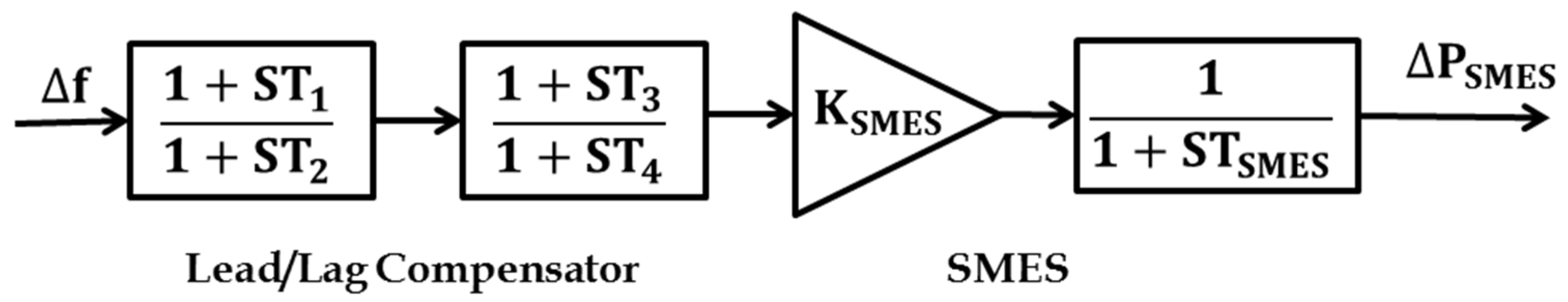
5.2. Superconducting Magnetic Energy Storage

SMES devices are one of the most prominent ESDs, as their static nature leads to higher efficiency. SMES involves no chemical reactions, and thus no harmful gases are exposed to atmosphere. This device comprises a magnetic circuit enclosed in a closed chamber, which is maintained at a cryogenic temperature to attain super conductivity. SMES devices also comprise power converter unit and a step-down transformer. The magnetic coil charging and discharging can be achieved through the transformer, and the interface between the SMES and grid is facilitated by the power converter unit. The charging of coil in SMES will be done during off-peak load durations and discharging at peak demands. The compensator model of SMES utilized in this paper for stabilizing frequency is displayed in Figure 5 [34]. The SMES device parameters are stabilization gain KSMES, and T1, T2, T3 and T4 are time constants.

5.3. Redoxflow Batteries

RFBs are one of the most effective ESDs based on the electrochemical reaction theory. Due to the benefits of a quick response nature and load-leveling characteristics, they have an extensive range of applications. Sulfuric acid solution with ions of vanadium acts as an electrolytic solution in RFBs for chemical reactions. RFBs comprising of two isolation chambers eliminate the problem of self-discharge. The oxidation and reduction reactions of the electrolytic solution in RFBs are responsible for the charging and discharging process. Its operation range depends upon the quantity of the electrolyte solution employed. In this paper, the workings of RFBs for the LFC study are given in Equation (14) [35].
Δ P r f b = { ( A C E K r f b ) ( K r i 1 + s T r i ) } ( 1 1 + s T d i ) ( s e t v a l u e )

6. HAEFA Algorithm

HAEFA is one of the newest meta-heuristic searching strategies developed by the researchers in [25]. Based on Coulomb’s law of electric field theory, the AEFA approach was implemented by the authors in [36]. This AEFA algorithm was implemented by the researchers especially for the control and operation of modern power system analysis and LFC studies and detected a drawback of updating the step size, which affects the effective utilization of search space. To overcome the above and to make the AEFA more effective in obtaining solutions for engineering optimization problems, the researchers in [25] put forward the hybridization mechanism and termed it the HAEFA algorithm. The implementation of this HAEFA approach is explained as follows:
First, initially randomize the gains of the controller in both LFC-AVR loops of the considered power system model as KPN, KIN, KDNN = 1,2,3…. n
X = [ K P 1 K I 1 K D 1 K P 2 K I 2 K D 2 K P N K I N K D N ]
The particles of each of the populations are updated in simulation. After performing the simulation for a given time period, the objective function values are calculated for each of the populations and treat them as local best solutions. The objective function conceived in this paper was ITAE, and the corresponding fitness function was evaluated as
f i t n e s s f u n c t i o n = 1 1 + I T A E I n d e x
Among the local best solutions, select the population that results in the lowest objective function value with the highest fitness value as the global best population. The respective solution is considered to be the global best solution, as the formulated objective function handles frequency and power deviations pertaining to multiple areas, which increases the problem complexity. Due to this the diversity of the solutions is increased. In order to bring the local best solutions towards the global best solution a novel velocity equation is formulated. In this equation the chaotic constants C1 and C2 are generated dynamically to change the particles’ velocity to favor the local and global best solutions. Using these local and global best solutions, the velocity of each of the populations can be calculated as
V i ( t + 1 ) = r a n d ( ) V i ( t ) + a i ( t ) + C 1 r a n d 1 ( ) ( P b e s t P c u r r e n t ) + C 2 r a n d 2 ( ) ( G b e s t G c u r r e n t )
Later, the particles position will be updated using
X i ( t + 1 ) = X i ( t ) + V i ( t + 1 )
where V i ( t + 1 ) and X i ( t + 1 ) represent velocity and the position of ith particle in the (t + 1) iteration, respectively. The chaotic parameters are varied dynamically to limit the chances of solution divergence using
C i = 1 + 1 1 + exp ( i t e r i t e r max ) , i = 1 , 2
The acceleration (a) and electric field (E) of ith particle at the (t + 1) iteration will be calculated as shown below.
a i ( t + 1 ) = Q i ( t + 1 ) E i ( t + 1 ) M i ( t + 1 )
E i ( t + 1 ) = F i ( t + 1 ) Q i ( t + 1 )
The total force exerting on ith particle in (t + 1) iteration as
F i ( t + 1 ) = j = 1 , j i n r a n d ( ) F i j ( t + 1 )
The force magnitude exerted on ith due to the jth particle in the (t + 1) iteration is
F i j ( t + 1 ) = K ( t + 1 ) Q i ( t + 1 ) Q j ( t + 1 ) ( P j ( t + 1 ) X j ( t + 1 ) ) R i j ( t + 1 )
where ‘K’ represents Coulomb’s constant, which can be calculated as
K ( t + 1 ) = K 0 exp ( α C u r r e n t i t e r a t i o n i t e r a t i o n max )
where K0 and α are constant parameters.
In order to maximize the force exerted by the electric field on the particles, half of the equivalent Euclidian distance is considered, as follows.
R i j ( t + 1 ) = 0.5 X i ( t + 1 ) X j ( t + 1 ) 2
Q i ( t + 1 ) = q i ( t + 1 ) i = 1 n q i ( t + 1 )
The charge of the ith and jth particles as indicated with Q i ( t + 1 ) and Q j ( t + 1 ) at the (t + 1) iteration is as follows.
q i ( t + 1 ) = exp ( f i t n e s s i ( t + 1 ) w o r s t ( t + 1 ) b e s t ( t + 1 ) w o r s t ( t + 1 ) )
The problem formulated in this paper is a minimization one, and hence the best and worst fitness values will be evaluated as
b e s t ( t + 1 ) = min ( f i t n e s s j ( t + 1 ) ) , j ( 1 , 2 , 3 ..... n )
w o r s t ( t + 1 ) = max ( f i t n e s s j ( t + 1 ) ) , j ( 1 , 2 , 3 ..... n )
This procedure is repeated for three iterations to train the populations to increase the searching capability. This is considered to be the first stage of the proposed algorithm. Here, after starting the iterative process, it takes a minimum of three iterations to obtain the decreased variance of deviation of the solutions. Using this statistical analysis, the developed algorithm generated first-stage solutions after three iterations. After this, the pair-wise comparison process was initiated to divide the total populations in half. The populations related to these solutions were forwarded to the second stage of the proposed methodology. Due to this, the remaining iterative process was performed with maximum efficacy to obtain the best solution within fewer iterations. The process of pair-wise comparison is as follows below:
Let f i t n e s s 1 , f i t n e s s 2 , f i t n e s s 3 ……….. f i t n e s s n be the fitness values of the solution for ‘n’ particles;
If f i t n e s s 1 > f i t n e s s 2 , then send f i t n e s s 1 to the next stage;
If f i t n e s s 3 > f i t n e s s 4 , then send f i t n e s s 3 to the next stage;
If f i t n e s s 5 > f i t n e s s 6 , then send f i t n e s s 5 to the next stage;
If f i t n e s s ( n 1 ) > f i t n e s s ( n ) , then send f i t n e s s ( n 1 ) to the next stage.
This process of pair-wise comparison was performed on all populations to obtain the best half of the entire population. The remaining algorithmic operations were performed on these populations.
After reviewing the literature carefully, it was noticed that the hybridization of multiple algorithms increases the algorithm’s performance to the maximum extent. From this, it was determined that in this paper a new hybridization approach was established by taking the advantage of crossover operation. As the considered objective function makes the problem more complex, it was necessary to obtain a converged solution instead of a diverged solution. From the fourth iteration onwards the existing crossover operation was performed on second-stage populations to minimize the solution divergence with updated velocity. Crossover can also be called recombination, which works to create offspring from two parents by combining the genetic information in a specified manner. It is the only way of generating new offspring stochastically from an existing population, which is analogous to the biological human reproduction system. There are various types of crossover operations available in the literature; however, after the conclusion of an extensive literature survey, it was determined that uniform crossover operation may yield better results, and it was thus implemented.
Y new = ( 1 λ ) × Y ref + λ × Y old
where λ is the random number between [0, 1] and Table 2, given below, indicates the uniform crossover operation.
After crossover operation the positions are updated; this whole procedure will be repeated till the completion of the maximum number of iterations, and then the best values are displayed. HAEFA flowchart is displayed in Figure 6.
Before implementing this strategy for power system optimization, the efficacy of hybridization was tested on the benchmark function of sphere function given in Equation (31). Both the algorithms were implemented with a population of 100 for 100 trials. The efficacy of the algorithm was assessed in terms of initial and final function values, as displayed in Figure 7. From Figure 7, it can be concluded that the function values at the initial and final instants were good, but a better solution was found using HAEFA as compared to the AEFA approach. Moreover, the final values of the function with HAEFA were almost below the mean value, which shows its effectiveness and tendency to maintain exploration and exploitation.
f ( x ) = i = 1 2 x i 2

7. Simulation Results

The simulation of the combined LFC and AVR system of MAIPS was designed in the domain of MATLAB/Simulink version (2016a), and the HAEFA optimization algorithm was developed in a (.m file) format. In order to assess the dynamical analysis, the combined LFC and AVR system was targeted with 10%SLP on area-1. The HAEFA algorithm was implemented with a population size of 50 for 100 iterations.

7.1. Case-1: Analysis of Combined LFC and AVR System with HAEFA-Tuned Controllers

The combined LFC and AVR model of MAIPS were analyzed with different controllers such as traditional PI/PID and intelligent-based fuzzy PID in both the loops of LFC and AVR one at a time by injecting area-1 with a load of 10% SLP. The parameters of these controllers were rendered optimally with a hybridized algorithm of the HAEFA approach. Figure 8 depicts the responses of the combined LFC-AVR system under various controllers fine-tuned with the HAEFA approach, and these responses were interpreted in terms of settling time, as provided in Table 3. After observing the responses rendered in Figure 8, we came to the decision that the undershooting and overshooting of the responses were very comfortably mitigated by the fuzzy PID compared to traditional PI/PID controllers. Moreover, the terminal voltages quickly reached specified values with the HAEFA-tuned fuzzy PID regulator. From Table 3, it is obvious that the responses reached the steady condition in much less time with the fuzzy PID controller than traditional PI/PID. Thus, the intelligent fuzzy PID showed its predominance in regulating the behavior of complex MAIPS of the LFC-AVR combined model. The parameters of PI/PID/fuzzy PID controllers that were retrieved optimally with the HAEFA technique are noted in Table 4. Further, the ITAE index value of the HAEFA-tuned fuzzy PID controller was improved by 54.19% with the HAEFA-based PI and 41.66% with HAEFA-based PID controllers.

7.2. Case-2: Analysis of System Performance with and without Considering AVR Coupling

In this sub section, a comparison has been made between the responses of the considered MAIPS without and with considering AVR coupling under the supervision of the HAEFA-tuned fuzzy PID controller. In order to obtain the analysis in more comparative approach, the power system with and without AVR coupling was analyzed for the same load disturbance, 10%SLP on area-1, and the responses are displayed in Figure 9. From the responses rendered in Figure 9, it can be noticed that the deviations in system behavior were slightly heightened with the consideration of AVR coupling, which can be justified by Equation (8). The stability of the power system depends on both terminal voltage and area frequency. The monitoring and regulation of voltage and frequency of the power system must be carried out with intense care. The mathematical analysis given in Equation (8) demonstrates the cumulative and simultaneous impact of variations in the AVR loop leading to the fluctuations in the LFC loop and vice versa. Considering all these analyses the ITAE objective function provided in Equation (12) is formulated for simultaneous voltage and frequency stabilization.

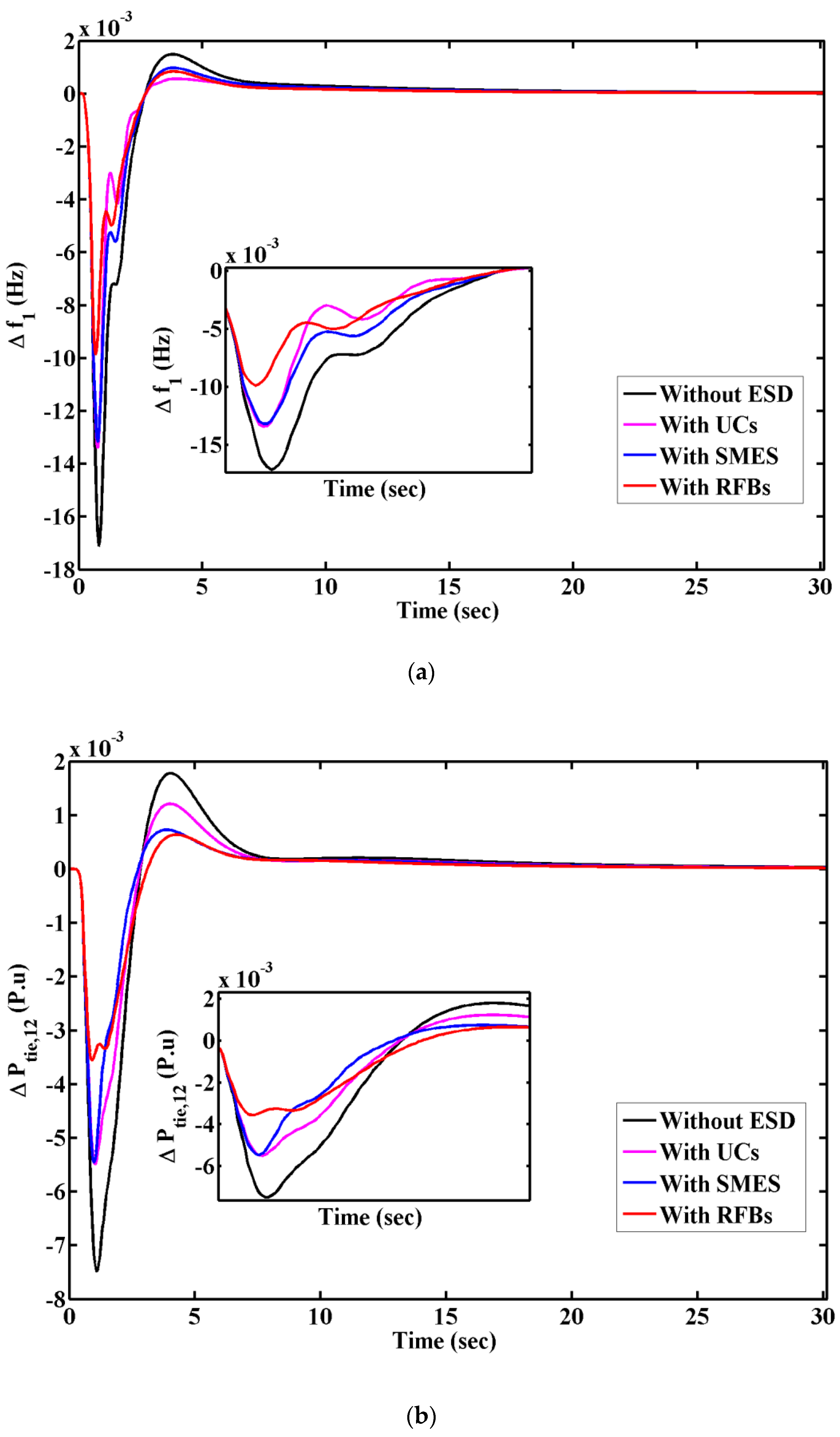
7.3. Case-3: Analysis of Combined LFC and AVR System with Different ESDs

The fuzzy PID regulator based on the HAEFA mechanism showed the supreme performance; as revealed in aforementioned cases, further analysis was performed under its supervision. The design of the secondary regulator alone was not sufficient to maintain the stability of the large complex interconnected power system networks. Thus, territorial control strategy was needed. Different ESDs such as RFBs, UCs and SMES were placed in both the areas of the LFC loop one after the other for the same load disturbances. The responses of the combined LFC-AVR system with different ESDs are compared in Figure 10 and were assessed numerically from a settling time point of view, as noted in Table 5, and they are further compared in the bar chart displayed in Figure 11 for easy observation. Analyzing the results depicted in Figure 11, we came to know that the deviations in frequency and line power flow were mitigated further, and the respective area terminal voltages were enhanced to a great extent. We also observed that for the different ESDs, such as RFBs, SMES and UCs, the RFBs showed more predominance in bringing the deviations in system responses to a steady condition more effectively. This was possible only because the quick response nature and lower cycle time of RFBs facilitates the complex combined LFC-AVR system to prevent hunting during load fluctuations compared to other ESDs.

8. Conclusions

The stability of frequency and voltage of the interconnected power system can be addressed simultaneously by connecting the AVR loop with the LFC using coupling coefficients. In this paper a HAEFA-tuned fuzzy PID was employed as a secondary regulator in both the LFC and AVR loops, and the dynamical analysis was carried out by laying area-1 with 10% SLP. The responses of LFC and AVR showcase the supremacy of fuzzy PID over classical PI and PID. Moreover, with fuzzy PID the ITAE function value was enhanced by 54.19% with PI and 41.67% with PID. However, the necessity of considering AVR coupling with the LFC loop was demonstrated and justified. Further, the combined system was incorporated with different ESDs such as RFBs, SMES and UCs one after the other in both the areas, and the system dynamical responses were compared to reveal the best one. The comparative results reveal that there as an enhancement in system dynamical behavior when incorporating ESDs in the view of the reduction in peak undershoot, overshoot and settling time. Moreover, out of all the ESDs the RFBs showed more predominance in the enhancement of system deviations and is recommended as the preferred territorial controller for the stability of interconnected power systems over the other ESDs.

Author Contributions

Conceptualization, C.N.S.K.; methodology, C.N.S.K.; validation, C.N.S.K., C.R.R., M.B. and S.K.; formal analysis, C.N.S.K., H.H.A. and P.S.; investigation, N.K.S. and M.B.; resources, B.S.G., S.K., H.H.A. and P.S.; writing—original draft preparation, C.N.S.K., C.R.R. and M.B.; writing—review and editing, N.K.S., C.N.S.K., M.B. and C.R.R.; visualization, B.S.G. and M.B. All authors have read and agreed to the published version of the manuscript.

Funding

This research received no external funding.

Institutional Review Board Statement

Not Applicable.

Informed Consent Statement

Not Applicable.

Data Availability Statement

No supplementary data available.

Acknowledgments

The authors thank the support of the National Research and Development Agency of Chile (ANID), ANID/Fondap/15110019.

Conflicts of Interest

The authors declare no conflict of interest.

References

  1. Kalyan, C.S.; Rao, G. Demonstrating the Effect of Excitation Cross Coupling and Communication Time Delays on Automatic Generation Control. In Proceedings of the 2021 4th Biennial International Conference on Nascent Technologies in Engineering (ICNTE), Virtual, 15–16 January 2021; pp. 1–6. [Google Scholar] [CrossRef]
  2. Fosha, C.E.; Elgerd, O.I. The Megawatt-Frequency Control Problem: A New Approach Via Optimal Control Theory. IEEE Trans. Power Appar. Syst. 1970, PAS-89, 563–577. [Google Scholar] [CrossRef]
  3. Dhanasekaran, B.; Siddhan, S.; Kaliannan, J. Ant colony optimization technique tuned controller for frequency regulation of single area nuclear power generating system. Microprocess. Microsyst. 2020, 73, 102953. [Google Scholar] [CrossRef]
  4. Mohanty, B.; Hota, P.K. A hybrid chemical reaction- particle swarm optimization technique for automatic generation control. J. Electr. Syst. Inf. Technol. 2018, 5, 229–244. [Google Scholar] [CrossRef]
  5. Yousri, D.; Babu, T.S.; Fathy, A. Recent methodology based Harris Hawks optimizer for designing load frequency control incorporated in multi-interconnected renewable energy plants. Sustain. Energy Grids Netw. 2020, 22, 100352. [Google Scholar] [CrossRef]
  6. Guha, D.; Roy, P.; Banerjee, S. Load frequency control of interconnected power system using grey wolf optimization. Swarm Evol. Comput. 2016, 27, 97–115. [Google Scholar] [CrossRef]
  7. Madasu, S.D.; Kumar, M.L.S.S.; Singh, A.K. A flower pollination algorithm based automatic generation control of inter-connected power system. Ain Shams Eng. J. 2018, 9, 1215–1224. [Google Scholar] [CrossRef] [Green Version]
  8. Hakimuddin, N.; Khosla, A.; Garg, J.K. Centralized and decentralized AGC schemes in 2-area interconnected power system considering multi source power plants in each area. J. King Saud Univ. Eng. Sci. 2020, 32, 123–132. [Google Scholar] [CrossRef]
  9. Barisal, A.; Mishra, S. Improved PSO based automatic generation control of multi-source nonlinear power systems interconnected by AC/DC links. Cogent Eng. 2018, 5, 1422228. [Google Scholar] [CrossRef]
  10. Kalyan, C.N.S.; Rao, G.S. Performance comparison of various energy storage devices in combined LFC and AVR of multi area system with renewable energy integration. Int. J. Renew. Energy Res. 2020, 10, 933–944. [Google Scholar]
  11. Kalyan, C.S.; Suresh, C.V. PIDD controller for AGC of nonlinear system with PEV integration and AC-DC links. In Proceedings of the 2021 International Conference on Sustainable Energy and Future Electric Transportation (SEFET), Virtual, 21–23 January 2021; pp. 1–6. [Google Scholar] [CrossRef]
  12. Tasnin, W.; Saika, L.C. Comparative performance of different energy storage devices in AGC of multi-source system in-cluding geothermal power plant. J. Renew. Sustain. Energy 2018, 10, 024101. [Google Scholar] [CrossRef]
  13. Zamani, A.; Barakati, S.M.; Yousofi-Darmian, S. Design of a fractional order PID controller using GBMO algorithm for load–frequency control with governor saturation consideration. ISA Trans. 2016, 64, 56–66. [Google Scholar] [CrossRef] [PubMed]
  14. Jain, S.; Hote, Y.V. Design of fractional PID for Load frequency control via Internal model control and Big bang Big crunch optimization. IFAC Pap. Line 2018, 51, 610–615. [Google Scholar] [CrossRef]
  15. Arya, Y.; Kumar, N. Design and analysis of BFOA- optimized fuzzy PI/PID controller for AGC of multi-area tradition-al/restructured electrical power systems. Soft Comput. 2017, 121, 6435–6452. [Google Scholar] [CrossRef]
  16. Rajesh, K.; Dash, S.; Rajagopal, R. Hybrid improved firefly-pattern search optimized fuzzy aided PID controller for automatic generation control of power systems with multi-type generations. Swarm Evol. Comput. 2019, 44, 200–211. [Google Scholar] [CrossRef]
  17. Nayak, J.R.; Shaw, B.; Sahu, B.K. Application of adaptive-SOS (ASOS) algorithm based interval type-2 fuzzy-PID controller with derivative filter for automatic generation control of an interconnected power system. Eng. Sci. Technol. Int. J. 2018, 21, 465–485. [Google Scholar] [CrossRef]
  18. Arya, Y. Improvement in automatic generation control of two-area electric power systems via a new fuzzy aided optimal PIDN-FOI controller. ISA Trans. 2018, 80, 475–490. [Google Scholar] [CrossRef] [PubMed]
  19. Gupta, A.; Chauhan, A.; Khanna, R.; Gupta, A.; Chauhan, A.; Khanna, R. Design of AVR and ALFC for single area power system including damping control. In Proceedings of the 2014 Recent Advances in Engineering and Computational Sciences (RAECS), Chandigarh, India, 6–8 March 2014; pp. 1–5. [Google Scholar] [CrossRef]
  20. Rakhshani, E.; Rouzbehi, K.; Sadeh, S. A New Combined Model for Simulation of Mutual Effects between LFC and AVR Loops. In Proceedings of the 2009 Asia-Pacific Power and Energy Engineering Conference, Wuhan, China, 28–30 March 2009; pp. 1–5. [Google Scholar] [CrossRef]
  21. Chandrakala, K.V.; Balamurugan, S. Simulated annealing based optimal frequency and terminal voltage control of multi source multi area system. Int. J. Electr. Power Energy Syst. 2016, 78, 823–829. [Google Scholar] [CrossRef]
  22. Rajabongshi, R.; Saikia, L.C. Conbined control of voltage and frequency of multi-area multisource system incorporating solar thermal power plant using LSA optimized classical controllers. IET Gener. Transm. Distrib. 2017, 11, 2489–2498. [Google Scholar] [CrossRef]
  23. Lal, D.K.; Barisal, A.K. Combined load frequency and terminal voltage control of power systems using moth flame optimization algorithm. J. Electr. Syst. Inf. Technol. 2019, 6, 1–24. [Google Scholar] [CrossRef] [Green Version]
  24. Kalyan, C.H.N.S.; Rao, G.S. Impact of communication time delays on combined LFC and AVR of a multi-area hybrid system with IPFC-RFBs coordinated control strategy. Prot. Control. Mod. Power Syst. 2021, 6, 1–20. [Google Scholar] [CrossRef]
  25. Kalyan, C.N.S.; Rao, G.S. Coordinated SMES and TCSC Damping Controller for Load Frequency Control of Multi Area Power System with Diverse Sources. Int. J. Electr. Eng. Inform. 2020, 12, 747–769. [Google Scholar] [CrossRef]
  26. Kalyan, C.N.S.; Rao, G.S. Frequency and voltage stabilisation in combined load frequency control and automatic voltage regulation of multiarea system with hybrid generation utilities by AC/DC links. Int. J. Sustain. Energy 2020, 39, 1009–1029. [Google Scholar] [CrossRef]
  27. Rajbongshi, R.; Saikia, L.C. Coordinated performance of interline power flow controller and superconducting magnetic energy storage in combined ALFC and AVR system under deregulated environment. J. Renew. Sustain. Energy 2018, 10, 044102. [Google Scholar] [CrossRef]
  28. Kalyan, C.N.S.; Venkateswarlu, A.N.; Reddy, C.R.; Goud, B.S.; Prasad, A.G.; Sriram, C.; Aymen, F. Frequency reg-ulation of multi area renewable energy source system with practical constraints under fractional-order fuzzy controller. Int. J. Renew. Energy Res. 2021, 11, 992–1002. [Google Scholar]
  29. Kalyan, C.N.S.; Rao, G.S. Performance Index-Based Coordinated Control Strategy for Simultaneous Frequency and Voltage Stabilization of Multi-area Interconnected System. In Control Applications in Modern Power System; Singh, A.K., Tripathy, M., Eds.; Lecture Notes in Electrical Engineering; Springer: Singapore, 2021; pp. 45–55. [Google Scholar] [CrossRef]
  30. Kalyan, C.N.S.; Rao, G.S. Coordinated control strategy for simultaneous frequency and voltage stabilisation of the multi-area interconnected system considering communication time delays. Int. J. Ambient. Energy 2021, 1–13. [Google Scholar] [CrossRef]
  31. Kalyan, C.N.S.; Suresh, C.V. Differential Evolution based Intelligent Control Approach for LFC of Multiarea Power System with Communication Time Delays. In Proceedings of the 2021 International Conference on Computing, Communication, and Intelligent Systems (ICCCIS), Greater Noida, India, 19–20 February 2021; pp. 868–873. [Google Scholar] [CrossRef]
  32. Kalyan, C.N.S.; Goud, B.S.; Reddy, C.R.; Ramadan, H.S.; Bajaj, M.; Ali, Z.M. Water Cycle Algorithm Optimized Type II Fuzzy Controller for Load Frequency Control of a Multi-Area, Multi-Fuel System with Communication Time Delays. Energies 2021, 14, 5387. [Google Scholar] [CrossRef]
  33. Kalyan, C.N.S.; Rao, G.S. Stabilizing Frequency and Voltage in Combined LFC and AVR System with Coordinated Performance of SMES and TCSC. In Control Applications in Modern Power System; Singh, A.K., Tripathy, M., Eds.; Lecture Notes in Electrical Engineering; Springer: Singapore, 2021; pp. 65–76. [Google Scholar] [CrossRef]
  34. Kalyan, C.N.S. UPFC and SMES based Coordinated Control Strategy for Simultaneous Frequency and Voltage Stability of an Interconnected Power System. In Proceedings of the 2021 1st International Conference on Power Electronics and Energy (ICPEE), Bhubaneswar, India, 2–3 January 2021; pp. 1–6. [Google Scholar] [CrossRef]
  35. Shankar, R.; Bhushan, R.; Chatterjee, K. Small-signal stability analysis for two-area interconnected power system with load frequency controller in coordination with FACTS and energy storage device. Ain Shams Eng. J. 2016, 7, 603–612. [Google Scholar] [CrossRef] [Green Version]
  36. Anita; Yadav, A. AEFA: Artificial electric field algorithm for global optimization. Swarm Evol. Comput. 2019, 48, 93–108. [Google Scholar] [CrossRef]
Figure 1. Combined LFC-AVR model of multi-area system.
Energies 15 00629 g001
Figure 2. AVR with coupling coefficients.
Energies 15 00629 g002
Figure 3. Fuzzy assisted PID controller.
Energies 15 00629 g003
Figure 4. MFs for FLC.
Energies 15 00629 g004
Figure 5. SMES structure.
Energies 15 00629 g005
Figure 6. HAEFA flowchart.
Energies 15 00629 g006
Figure 7. Sphere function objective value at initial and final instant using AEFA and HAEFA methods for 100 trials.
Energies 15 00629 g007
Figure 8. Responses for case-1: (a). ∆f1, (b). ∆Ptie12, (c). ∆f2, (d). V1 and (e). V2.
Energies 15 00629 g008aEnergies 15 00629 g008bEnergies 15 00629 g008c
Figure 9. Responses for case-2: (a). ∆f1, (b). ∆Ptie12 and (c). ∆f2.
Energies 15 00629 g009aEnergies 15 00629 g009b
Figure 10. Responses for case-3: (a). ∆f1, (b). ∆Ptie12, (c). ∆f2, (d). V1 and (e). V2.
Energies 15 00629 g010aEnergies 15 00629 g010bEnergies 15 00629 g010c
Figure 11. Comparison of responses’ settling time (in seconds on Y-axis) for different ESDs.
Energies 15 00629 g011
Table 1. FLC input and output rules.
ACE∆ACE
BNSNZSPBP
BNBNBNBNSNZ
SNBNBNSNZSP
ZBNSNZSPBP
SPSNZSPBPBP
BPBPZSPBPBP
Table 2. Uniform crossover operation.
Parent10 1 0 0 0 1 0 1
Parent20 0 1 1 0 1 0 0
Mask1 0 0 1 0 1 1 0
Child10 1 0 1 0 1 0 1
Child20 0 1 0 0 1 0 0
Table 3. Settling time of responses in case-1.
HAEFA-Based ControllersSettling Time TS (Sec)ITAE
∆f1∆f2∆Ptie12V1V2
PI26.8826.6227.948.1248.79136.134
PID23.4524.1122.936.5247.81128.376
Fuzzy PID15.2311.0317.345.1274.15716.552
Table 4. Controller optimal gains found with HAEFA technique.
HAEFA Tuned ControllerArea-1Area-2
LFC LoopAVR LoopLFC LoopAVR Loop
PIKP = 3.1324
KI = 2.1487
KP = 2.0119
KI = 1.1576
KP = 2.9034
KI = 1.8270
KP = 1.9085
KI = 1.0864
PIDKP = 3.3517
KI = 2.4854
KD = 0.9649
KP = 2.2510
KI = 1.3472
KD = 0.4976
KP = 2.8909
KI = 2.1869
KD = 0.9595
KP = 2.3413
KI = 1.3718
KD = 0.8693
Fuzzy PIDKP = 3.7679
KI = 1.9755
KD = 1.2769
KP = 2.0457
KI = 1.0844
KD = 0.9961
KP = 3.4509
KI = 1.9924
KD = 0.9133
KP = 2.3015
KI = 1.1554
KD = 0.9419
Table 5. Settling time of responses for case-3.
HAEFA: Fuzzy PID Settling   Time   T S   ( Sec )
∆f1∆f2∆Ptie12V1V2
Without ESD15.2311.0317.345.1274.157
With UCs14.559.9216.904.1253.821
With SMES12.899.8116.253.2402.801
With RFBs11.618.2815.592.2142.026
Publisher’s Note: MDPI stays neutral with regard to jurisdictional claims in published maps and institutional affiliations.

