
Overview of Propulsion Systems for Unmanned Aerial Vehicles


Abstract
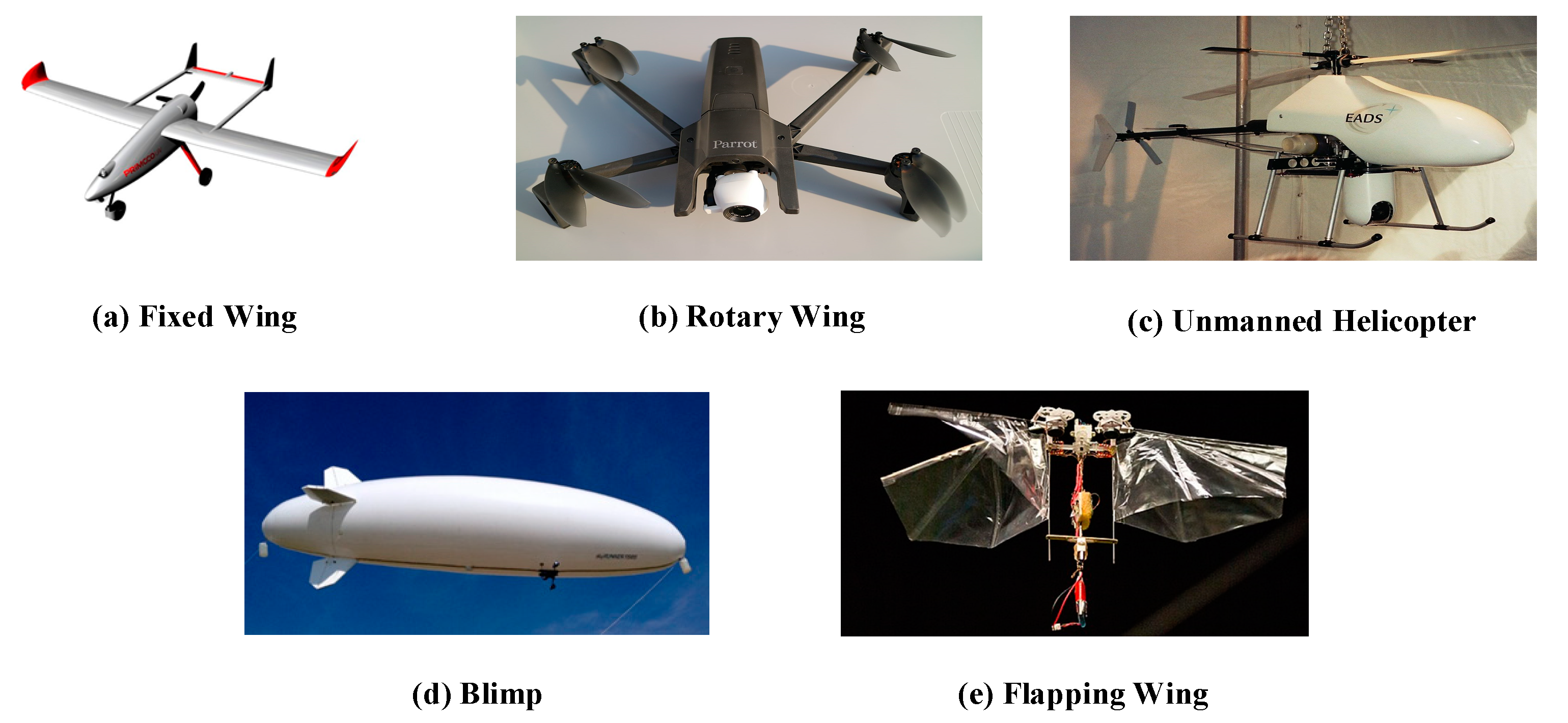
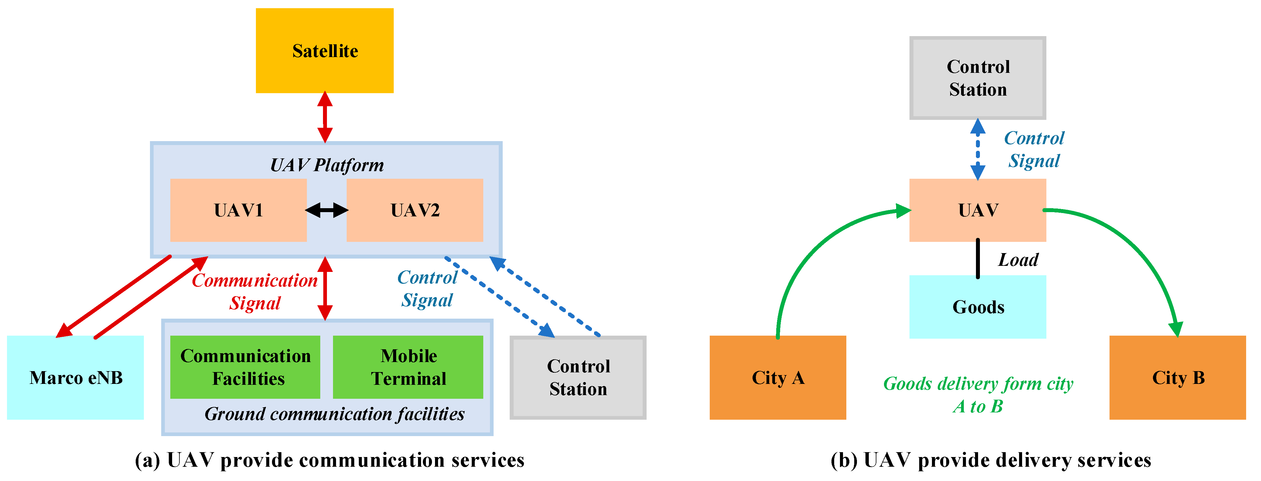
:1. Introduction
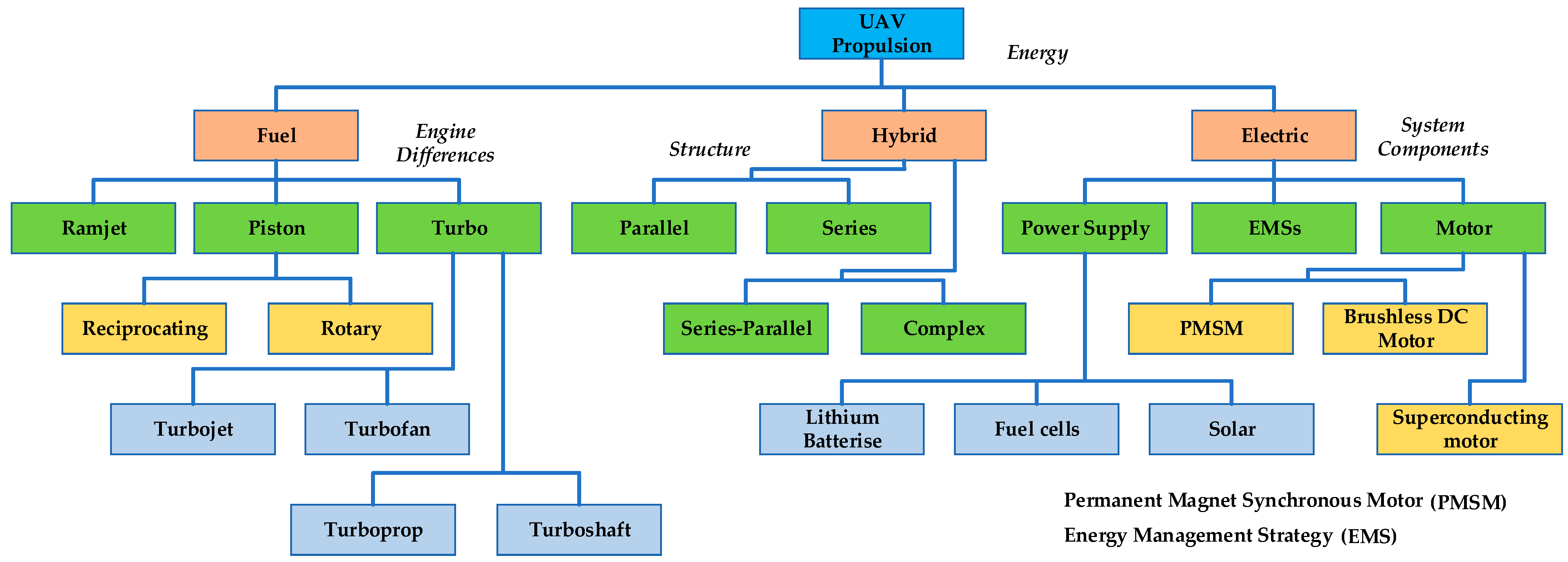
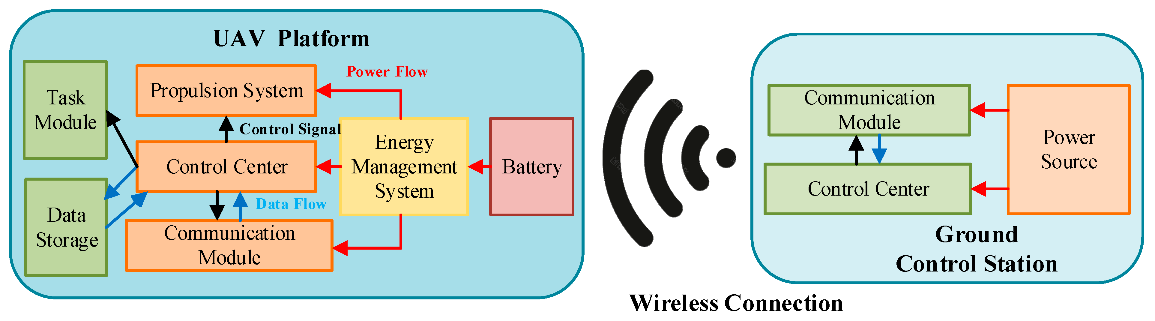
2. Propulsion System Configuration of UAVs
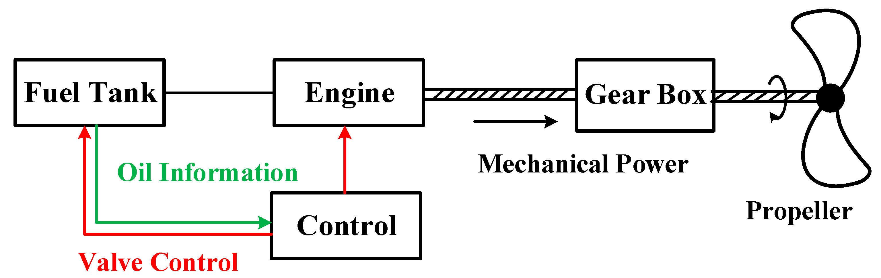
3. Fuel Propulsion System for UAV
3.1. Piston Engine
- (1)
- Mature technology: Piston engines have been developed over a long period, and their technology has matured. So, the use of piston engines affects the weight of the load carried by the UAV.
- (2)
- Simple structure: Compared to turbine engines, piston engines have a more straightforward structure. It is easier for daily maintenance of piston engines easier.
- (3)
- Low cost: The piston engine is cheaper to manufacture and use and has good economy and reliability. It is suitable for the application of small and medium-sized UAV propulsion systems.
- (1)
- Low power-to-weight ratio: Compared with turbine engines, the power-to-weight ratio of piston engines is low. So, the use of piston engines affects the weight of the load carried by the UAV.
- (2)
- Speed limitation: Because the piston engine drives the propeller rotation to generate thrust, its maximum speed cannot exceed the speed of sound, so it cannot meet the needs of high-speed UAVs.
- (3)
- Poor performance at high altitude: Since the piston engine needs to inhale a large amount of air during operation, the performance of the piston engine will be significantly affected in the environment of thin air at high altitudes.
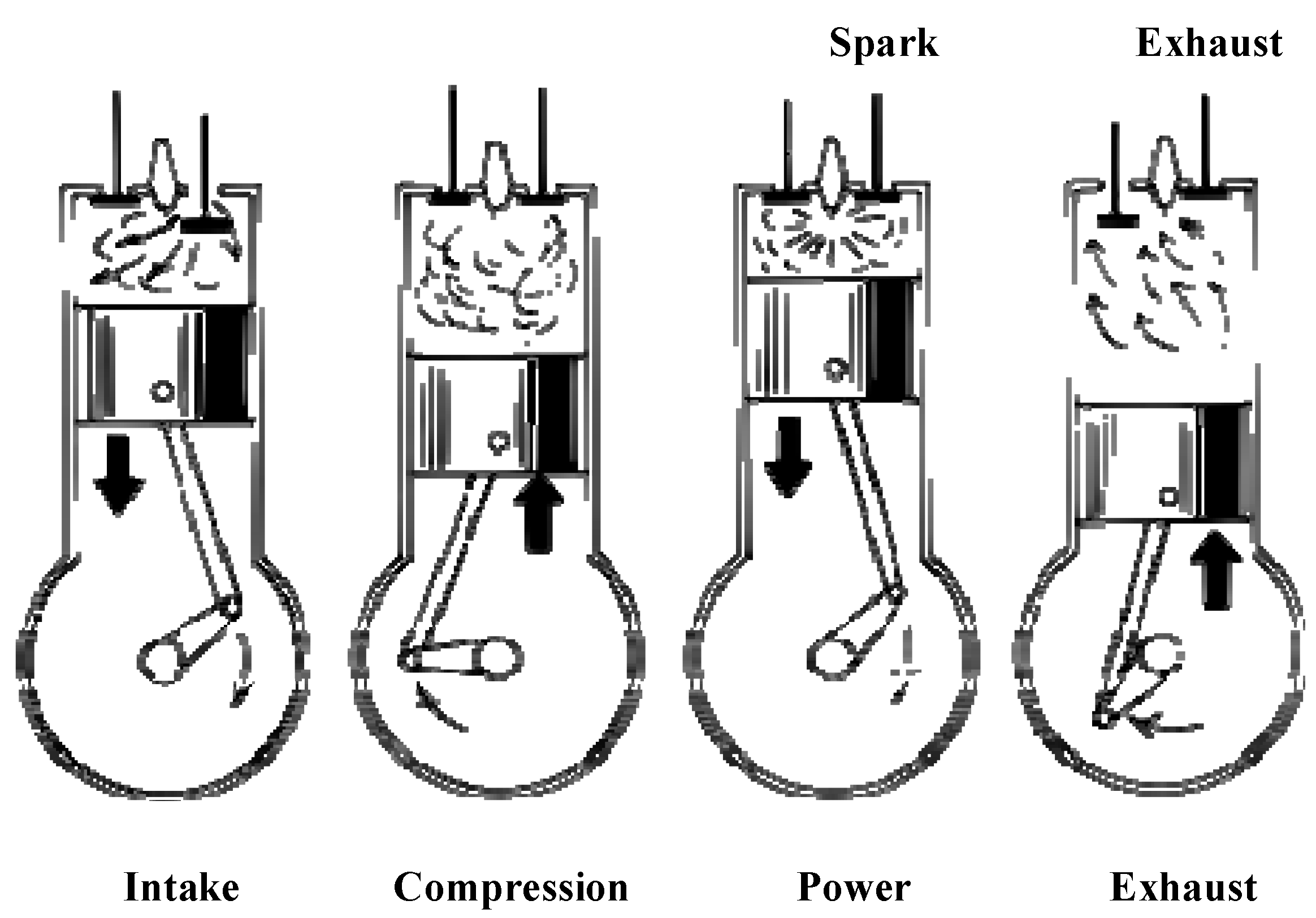
3.1.1. Reciprocating Piston Engine
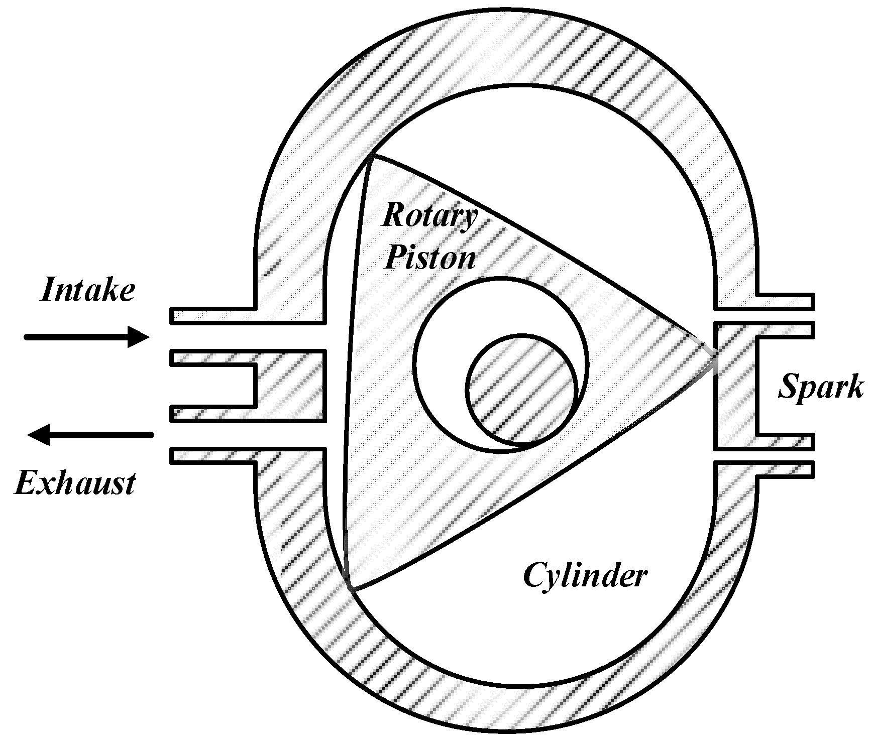
3.1.2. Rotary Engine
3.1.3. Key Technologies of Piston Engine
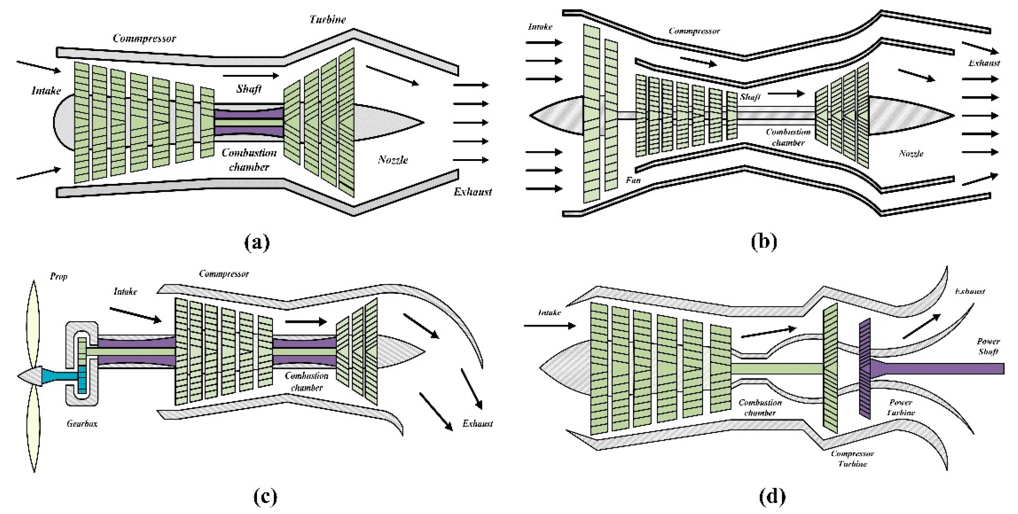
3.2. Turbo Engine
3.2.1. Turbojet Engine
3.2.2. Turbofan Engine
3.2.3. Turboprop Engine
3.2.4. Turboshaft Engine
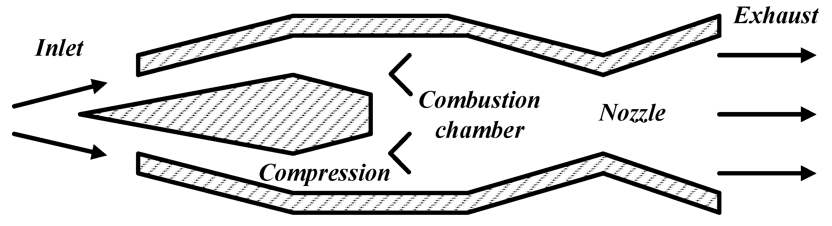
3.3. Ramjet Engine
4. Fuel-Electric Hybrid Propulsion System for UAV
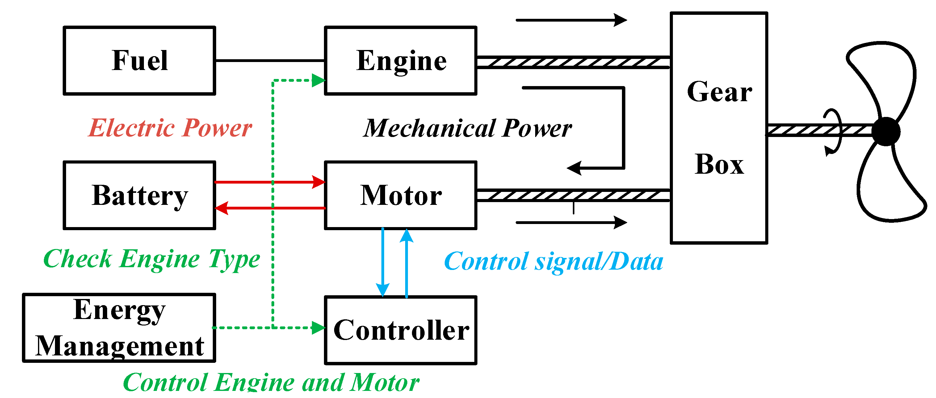
4.1. Parallel Hybrid Structure
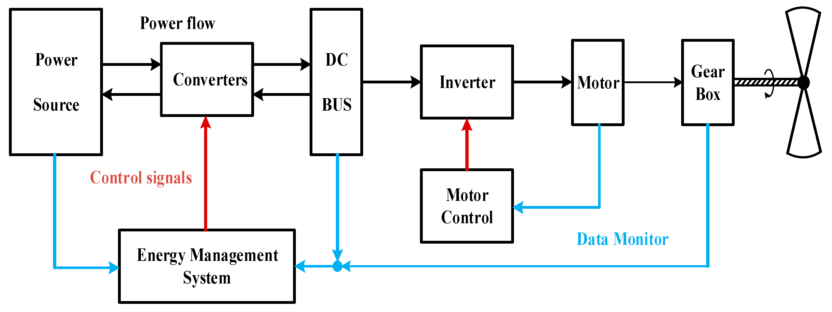
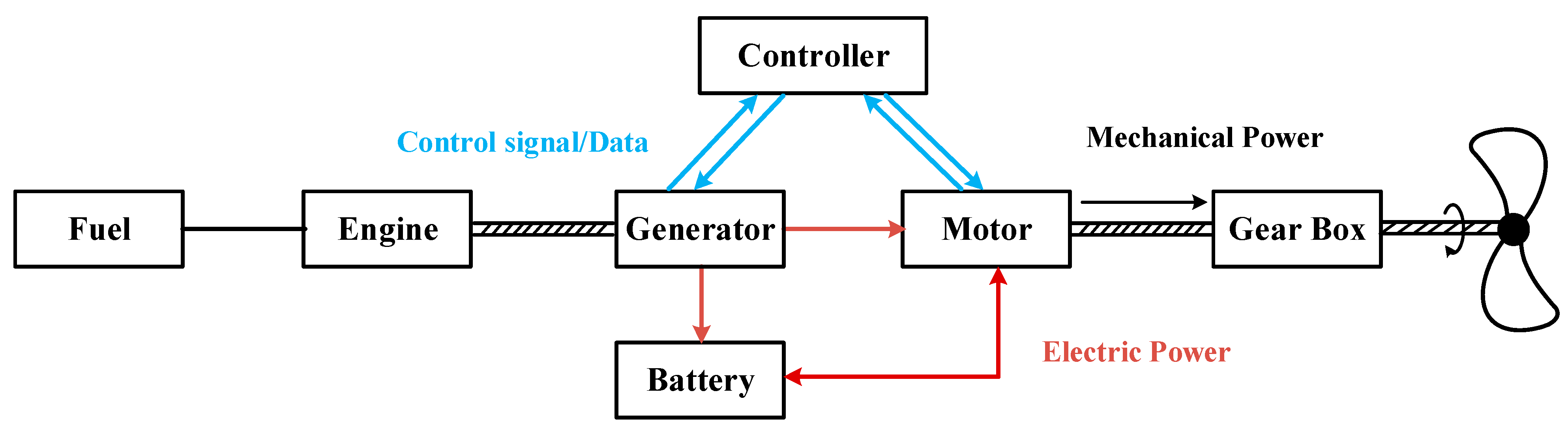
4.2. Series Hybrid Structure
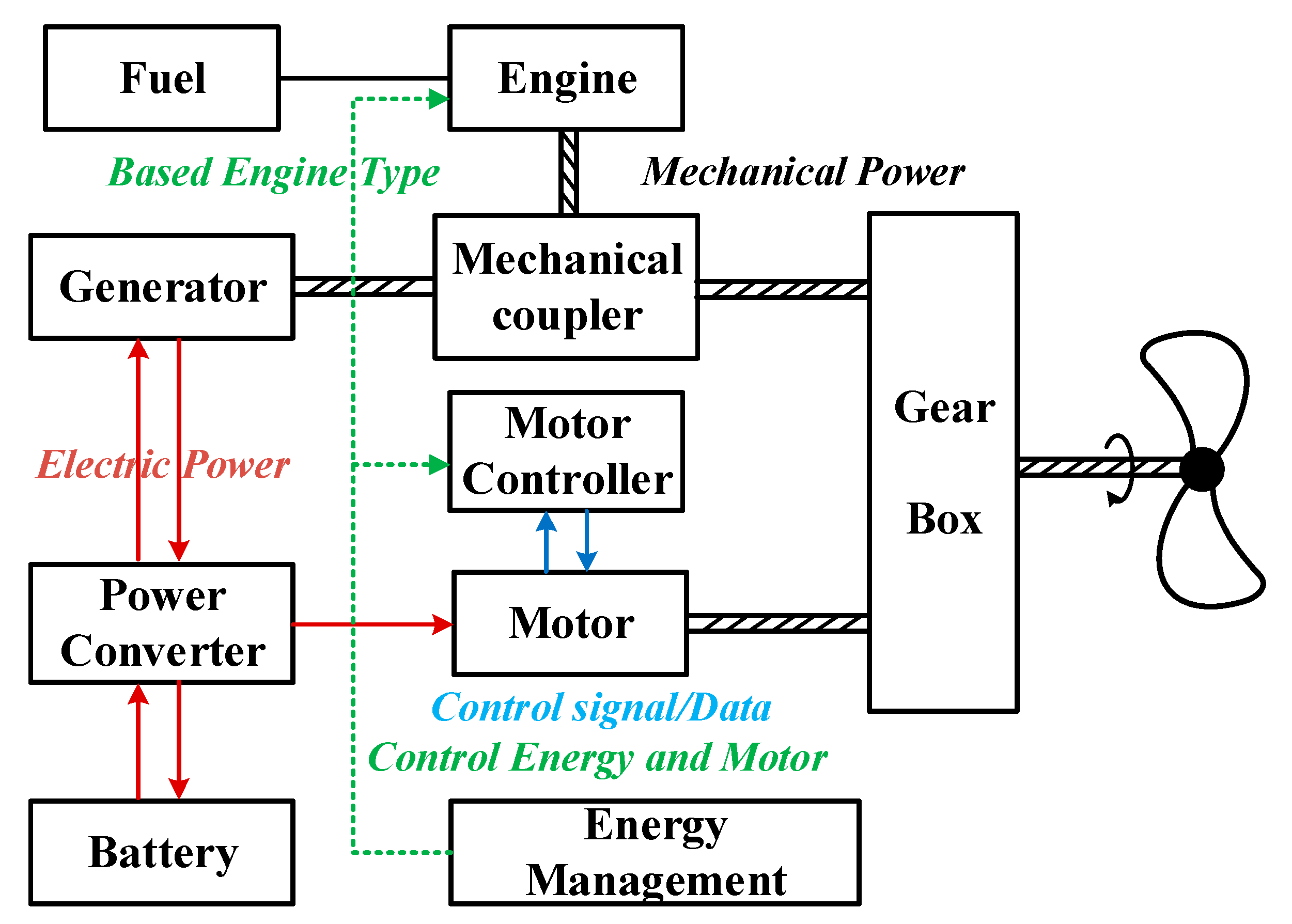
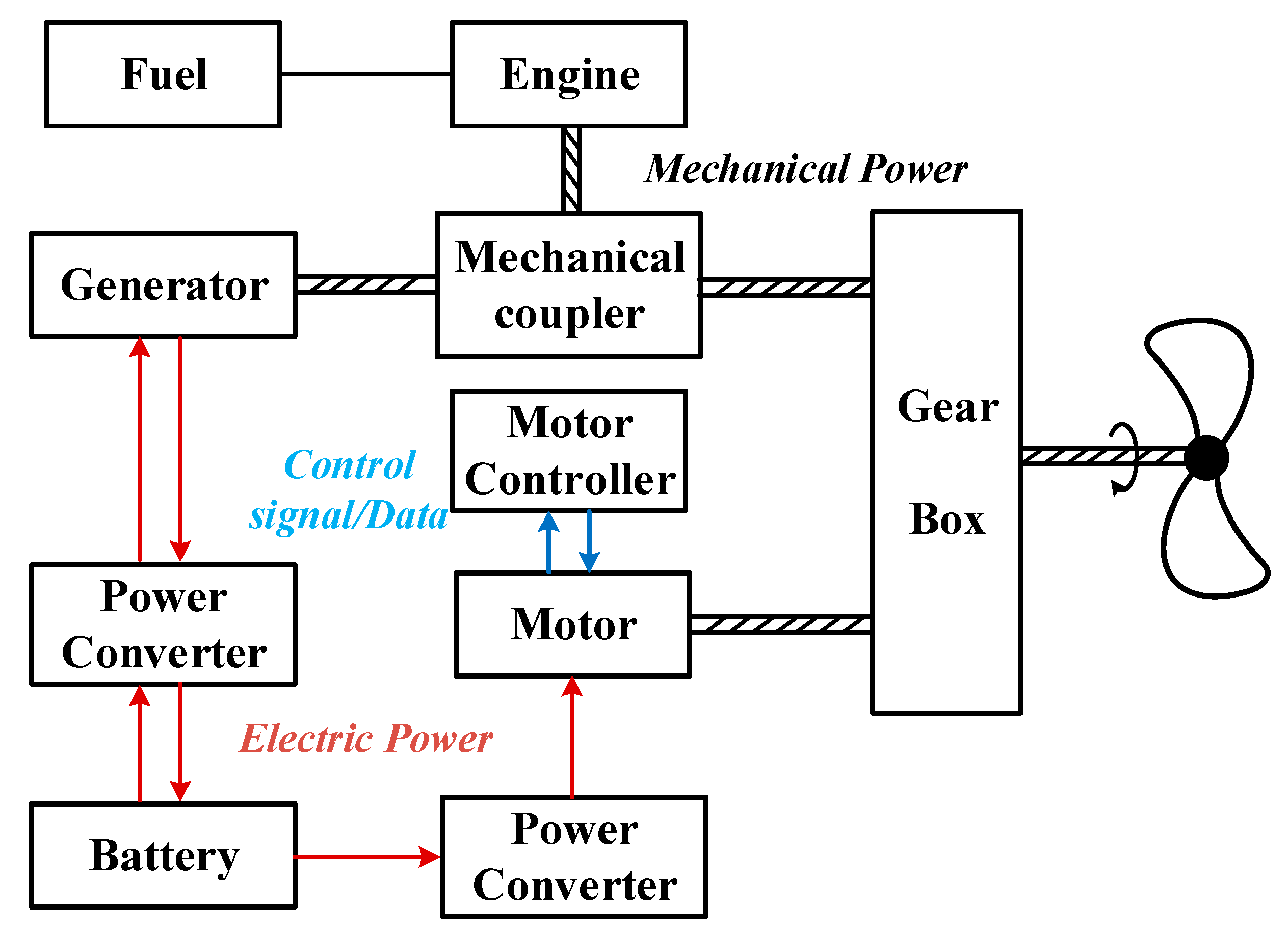
4.3. Series-Parallel Hybrid Structure
5. Electric Propulsion System for UAV
- (1)
- Environmentally friendly: Electric propulsion UAVs use electrical energy as a power source, thus reducing fuel consumption and pollutant emissions. At the same time, this contributes to solving the increasingly tight energy problem and significantly reduces carbon emissions.
- (2)
- Design versatility: Electric propulsion UAVs use electric motors to generate thrust and thus have a distributed layout. It allows for more aerodynamic layouts for better flight performance, which in turn can meet specific needs.
- (3)
- Wide range of energy sources: Fuel cells, solar energy, and lithium batteries can all be used as energy sources for electric propulsion drones.
- (4)
- Simple structure: The UAV electric propulsion system has a simple structure and is much easier to repair and maintain.
- (1)
- Low energy density of energy storage devices: the current lithium battery energy density is insufficient, resulting in the weight of the battery carried being too large to meet the needs of the use of electric propulsion UAV.
- (2)
- High cost: The key components of electric propulsion systems, such as lithium batteries, are costly. As the electric propulsion technology is not yet mature, the high development cost restricts its further application.
- (3)
- Insufficient environmental adaptability: electric propulsion UAVs are challenging to make work satisfactorily in lousy weather. In the complex electromagnetic environment, the reliability of the electric propulsion system will be reduced to a certain extent.
5.1. UAVs Electric Propulsion System Power Supply
5.1.1. Lithium Batteries
5.1.2. Fuel Cells
5.1.3. Solar Photovoltaic
5.2. Electric Propulsion System Power Units
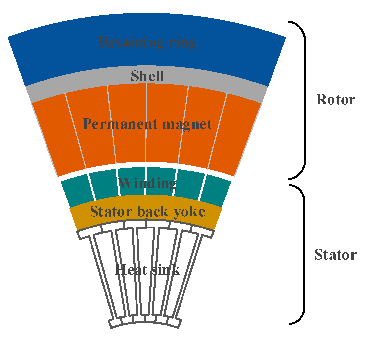
5.2.1. Permanent Magnet Synchronous Motor
5.2.2. Permanent Magnet Brushless DC Motor
5.2.3. Superconducting Motors
6. Conclusions and Prospect
- (1)
- With the increasingly severe problems of energy and the environment, the problems of fuel propulsion pollution systems should be solved in effective ways. Fuel propulsion systems will develop toward higher efficiency, such as heavy oil technology to fully utilize most fossil fuels.
- (2)
- The hybrid fuel-electric propulsion system can significantly improve the UAV flight efficiency and save fuel consumption. Over time, it can provide sufficient power for UAVs, and it can reduce energy consumption, which is suitable for a wide range of medium and large UAV applications.
- (3)
- The electric propulsion system will become one of the mainstreams for future UAV propulsion systems thanks to its advantages of environmental protection, comprehensive energy source, and diverse aerodynamic layout.
- (4)
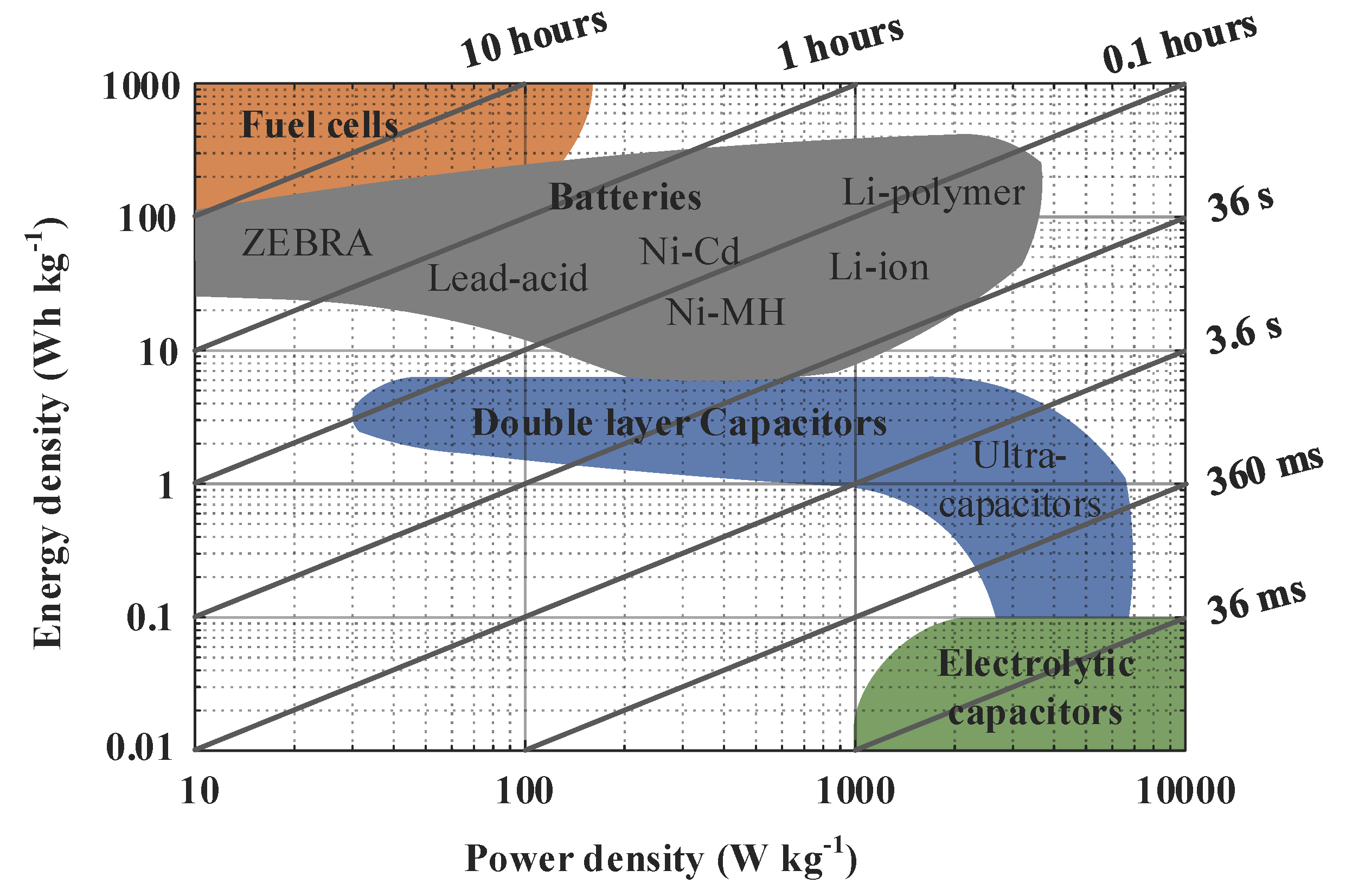
- The UAV electric propulsion system needs to select suitable energy storage devices with the high-power density and high energy density. The fuel cell has a broad development prospect at present.
- (5)
- The distributed electric propulsion system will make the UAV have a more aerodynamic layout, and the development of a high-power density permanent magnet synchronous motor will make it have a higher power-weight ratio.
- (6)
- The use of superconducting motors will effectively solve the power and heat dissipation problem of UAV motors, thus reducing the weight and volume.
- (1)
- Safe, reliable, and high-density energy storage technology. At present, the energy density of lithium batteries is still not enough, and fuel cells have a large volume and weight due to the hydrogen storage device and control device. The storage of hydrogen has a particular danger, which leads to the low load-to-weight ratio of electric propulsion UAVs. This could become the biggest problem that restricts the application of electric propulsion systems.
- (2)
- High power density motor technology. UAV electric propulsion systems in the future need to reduce the volume weight to improve the load capacity. And a high-power density motor has a smaller volume weight and can produce a higher propulsion power. When the power density of the electric propulsion system has 3~8 kW/kg, it has the additional practical value.
- (3)
- High efficiency and high-power density converter. The high-power density converters play a vital role in electric propulsion systems, and the control of motors often requires large-capacity power converters, such as rectifiers and inverters. The electric propulsion system will adopt the larger power converters, which will bring much more losses. Additionally, the high-efficiency power converters can save energy consumption and increase the range and endurance of the UAV.
- (4)
- Efficient heat management technology. The electric propulsion system will use many electronic components, which will inevitably bring a lot of heat. Excessive heat accumulation in the UAV that cannot be dissipated will affect the device service life. For instance, the healthy cooling can improve the current density of the motor winding, reduce the conduction loss of the switching tube, and extend the service life of the motor insulation layer. Therefore, UAV electric propulsion systems require the thermal management techniques that are small, efficient, and suitable for distributed systems.
Author Contributions
Funding
Institutional Review Board Statement
Informed Consent Statement
Data Availability Statement
Conflicts of Interest
References
- Aasen, H.; Honkavaara, E.; Lucieer, A.; Zarco-Tejada, P.J. Quantitative remote sensing at ultra-high resolution with UAV spectroscopy: A review of sensor technology, measurement procedures, and data correction workflows. Remote. Sensing. 2018, 10, 1091. [Google Scholar] [CrossRef] [Green Version]
- Abdullah, M.; Faizan, M.; Bhatti, M.Y.; Hasham, H.J. System design and analysis of hand lunched UAV. In Proceedings of the 14th International Bhurban Conference on Applied Sciences and Technology (IBCAST), Islamabad, Pakistan, 10–14 January 2017; pp. 551–560. [Google Scholar]
- Adamo, F.; Andria, G.; Di-Nisio, A.; Carducci, C.G.C.; Lanzolla, A.M.; Mattencini, G. Development and characterization of a measurement instrumentation system for UAV components testing. In Proceedings of the IEEE International Workshop on Metrology for AeroSpace, Padua, Italy, 21–23 June 2017; pp. 355–359. [Google Scholar]
- Gao, X.; Liu, C.; Huang, Y.; Song, Z. Design of an UAV-oriented wireless power transfer system with energy-efficient receiver. In Proceedings of the IECON 2020 The 46th Annual Conference of the IEEE Industrial Electronics Society, Singapore, 18–21 October 2020; pp. 2025–2030. [Google Scholar]
- Valavanis, K.P.; Vachtsevanos, G.J. Handbook of Unmanned Aerial Vehicles; Springer: Dordrecht, The Netherlands, 2015; Volume 2077. [Google Scholar]
- Semetkovsky; Primoco UAV 2. 2015. Available online: https://commons.wikimedia.org/wiki/File:Primoco_UAV_2.jpg (accessed on 1 September 2021).
- KlausFoehl. Parrot Anafi Drone. 2018. Available online: https://commons.wikimedia.org/wiki/File:Parrot_Anafi_Drone01_2018-07-19.jpg (accessed on 1 September 2021).
- David, M. EADS Drone. 2005. Available online: https://commons.wikimedia.org/wiki/File:EADS_drone_fh000011.jpg (accessed on 1 September 2021).
- Princo85; Skyrunner 11000 UAV Blimp. 2012. Available online: https://commons.wikimedia.org/wiki/File:SkyRUNNER_11000_UAV_Blimp.JPG (accessed on 1 September 2021).
- MatejTU. DelFly Nimble. 2018. Available online: https://commons.wikimedia.org/wiki/File:DelFly_Nimble.jpg (accessed on 7 September 2021).
- Rami Mizrahi. 4X-UEB Rami-Mizrahi. 2013. Available online: https://commons.wikimedia.org/wiki/File:4X-UEB_Rami-Mizrahi.jpg (accessed on 2 September 2021).
- Boon, M.A.; Drijfhout, A.P.; Tesfamichael, S. Comparison of a fixed-wing and multi-rotor UAV for environmental mapping applications: A case study. Int. Arch. Photogramm. Remote Sens. Spat. Inf. Sci. 2017, 42, 47. [Google Scholar] [CrossRef] [Green Version]
- Brown, S.T.; Lambrigtsen, B.; Denning, R.F.; Gaier, T.; Kangaslahti, P.; Lim, B.H.; Tanner, A.B. The high-altitude MMIC sounding radiometer for the global hawk unmanned aerial vehicle: Instrument description and performance. IEEE Trans. Geosci. Remote Sens. 2011, 49, 3291–3301. [Google Scholar] [CrossRef]
- Azeta, J.; Ishola, F.; Akinpelu, T.; Bolu, C.; Dirisu, J.; Fajobi, M.A.; Salawu, E.Y. An experimental evaluation of LTA on the performance of a drone. Procedia Manuf. 2019, 35, 1135–1140. [Google Scholar] [CrossRef]
- Wikipedia Northrop Grumman RQ-4 Global Hawk. Available online: https://en.wikipedia.org/wiki/Northrop_Grumman_RQ-4_Global_Hawk (accessed on 2 September 2021).
- Singh, A. Unmanned and Autonomous Vehicles and Future Maritime Operations in Littoral Asia. In ORF Special Report; Observer Research Foundation: Delhi, India, 28 July 2016; pp. 3–12. [Google Scholar]
- Wikipedia Schiebel Camcopter S-100. Available online: https://en.wikipedia.org/wiki/Schiebel_Camcopter_S-100 (accessed on 3 September 2021).
- Vantage Airship Ca Series. Available online: https://en.wikipedia.org/wiki/Vantage_Airship#CA_series (accessed on 3 September 2021).
- AI Bird UAV SY-2000. Available online: https://en.wikipedia.org/wiki/AI_Bird_UAV#SY-2000 (accessed on 4 September 2021).
- Airforce Technology A160 Hummingbird Unmanned Rotorcraft. Available online: https://www.airforce-technology.com/projects/hummingbird/ (accessed on 3 September 2021).
- Minnick, W. Zhuhai airshow goes unmanned. Defense News, 20 November 2010; p. 18. [Google Scholar]
- Gerdes, J.; Holness, A.; Perez-Rosado, A.; Roberts, L.; Greisinger, A.; Barnett, E.; Gupta, S.K. Robo Raven: A flapping-wing air vehicle with highly compliant and independently controlled wings. Soft Robot. 2014, 1, 275–288. [Google Scholar] [CrossRef]
- Homainejad, N.; Rizos, C. Application of multiple categories of unmanned aircraft systems (UAS) in different airspaces for bushfire monitoring and response. Int. Arch. Photogramm. Remote. Sens. Spat. Inf. Sci. 2015, 40, 55–60. [Google Scholar] [CrossRef] [Green Version]
- Cullen, T.M. The MQ-9 reaper remotely piloted aircraft: Humans and machines in action. Ph.D. Thesis, Massachusetts Institute of Technology, Cambridge, MA, USA, 2011. [Google Scholar]
- Kania, E. The PLA’s Unmanned Aerial Systems: New Capabilities for a” New Era” of Chinese Military Power. Ph.D. Thesis, China Aerospace Studies Institute, Wright Patterson, AL, USA, 2018. [Google Scholar]
- Cole, C. Drone Wars Briefing; Drone Wars UK: Oxford, UK, 2012. [Google Scholar]
- Baiocchi, V.; Dominici, D.; Mormile, M. UAV application in post-seismic environment. In Proceedings of the International Archives of the Photogrammetry, Remote Sensing and Spatial Information Sciences, Rostock, Germany, 4–6 September 2013. [Google Scholar]
- Adão, T.; Hruška, J.; Pádua, L.; Bessa, J.; Peres, E.; Morais, R.; Sousa, J.J. Hyperspectral imaging: A review on UAV-based sensors, data processing and applications for agriculture and forestry. Remote Sens. 2017, 9, 1110. [Google Scholar] [CrossRef] [Green Version]
- Chiang, W.C.; Li, Y.; Shang, J.; Urban, T.L. Impact of drone delivery on sustainability and cost: Realizing the UAV potential through vehicle routing optimization. Appl. Energy 2019, 242, 1164–1175. [Google Scholar] [CrossRef]
- Qi, H.; Hu, Z.; Huang, H.; Wen, X.; Lu, Z. Energy efficient 3-D UAV control for persistent communication service and fairness: A deep reinforcement learning approach. IEEE Access. 2020, 8, 53172–53184. [Google Scholar] [CrossRef]
- Fan, A.; Liu, X.Z. Chinese Drones Provide Lifeline Network Services for Flood-Stranded Residents. 2021. Available online: https://www.globaltimes.cn/page/202107/1229363.shtml (accessed on 6 September 2021).
- Zhou, C.; Yin, J.; Rong, A.; Guo, D.; Li, J. Research on UAV fire fight based on analytic hierarchy process. In Proceedings of the 2021 International Conference on Control and Intelligent Robotics, Liu Zhou, China, 18–20 June 2021; pp. 16–22. [Google Scholar]
- Di, L. Tian Loong I Fire Fight UAV. 2019. Available online: https://k.sina.com.cn/article_1726918143_66eeadff02000tkw2.html (accessed on 6 September 2021).
- Fahlstrom, P.; Gleason, T. Introduction to UAV Systems; John Wiley & Sons: Manhattan, NY, USA, 2012. [Google Scholar]
- Liu, C.; Yu, J.; Lee, C.H. A new electric magnetic-geared machine for electric unmanned aerial vehicles. IEEE Trans. Magn. 2017, 53, 1–6. [Google Scholar] [CrossRef]
- Kong, X.; Liu, H. Research progress of key technologies of aviation piston engine for UAV. Small Intern. Combust. Engine Veh. Tech. 2021, 50, 3. [Google Scholar]
- Kong, X.; Zhang, Z.; Lu, J.; Li, J.; Yu, L. Review of electric power system of distributed electric propulsion aircraft. Acta Aeronaut. Astronaut. Sin. 2018, 39, 021651. [Google Scholar]
- Huang, J. Survey on design technology of distributed electric propulsion aircraft. Acta Aeronaut. Astronaut. Sin. 2021, 42, 624037. [Google Scholar]
- Boukoberine, M.N.; Zhou, Z.; Benbouzid, M.A. Critical review on unmanned aerial vehicles power supply and energy management: Solutions, strategies, and prospects. Appl. Energy 2019, 255, 113823. [Google Scholar] [CrossRef]
- Zhang, X. Distributed electric propulsion technology oriented to 2030. In Proceedings of the 2nd China Aviation Science and Technology Conference, Beijing, China, 15 September 2015; pp. 330–334. [Google Scholar]
- Schiltgen, B.; Gibson, A.; Green, M.; Freeman, J. More electric aircraft: Tube and wing hybrid electric distributed propulsion with superconducting and conventional electric machines. SAE International, 17 September 2013; 1–23. [Google Scholar]
- Zhang, X.; Gao, Z.; Lei, T.; Min, Z.; Lei, W.; Zhang, X. Ground test research on aerodynamic/propulsion coupling characteristics of distributed electric propulsion aircraft. Acta Aeronaut. Astronaut. Sin. 2021, 42. [Google Scholar] [CrossRef]
- Cai, G.; Dias, J.; Seneviratne, L. A survey of small-scale unmanned aerial vehicles: Recent advances and future development trends. Unmanned Syst. 2014, 2, 175–199. [Google Scholar] [CrossRef] [Green Version]
- Cevik, P.; Kocaman, I.; Akgul, A.S.; Akca, B. The small and silent force multiplier: A swarm UAV—Electronic attack. J. Intell. Robot. Syst. 2013, 70, 595–608. [Google Scholar] [CrossRef]
- Yang, C.; Zha, M.; Wang, W.; Liu, K.; Xiang, C. Efficient energy management strategy for hybrid electric vehicles/plug-in hybrid electric vehicles: Review and recent advances under intelligent transportation system. IET Intell. Transp. Syst. 2020, 14, 702–711. [Google Scholar] [CrossRef]
- Liu, S.; Liu, C. Direct harmonic current control scheme for dual three-phase PMSM drive system. IEEE Trans. Power Electron. 2021, 36, 11647–11657. [Google Scholar] [CrossRef]
- Glasgo, B.; Azevedo, I.L.; Hendrickson, C. How much electricity can we save by using direct current circuits in homes? Understanding the potential for electricity savings and assessing feasibility of a transition towards DC powered buildings. Appl. Energy 2016, 180, 66–75. [Google Scholar] [CrossRef] [Green Version]
- Amezquita-Brooks, L.; Hernandez-Alcantara, D.; Santana-Delgado, C.; Covarrubias-Fabela, R.; Garcia-Salazar, O.; Ramirez-Mendoza, A.M. Improved model for micro-UAV propulsion systems: Characterization and applications. IEEE Trans. Aerosp. Electron. Syst. 2019, 56, 2174–2197. [Google Scholar] [CrossRef]
- Mikalsen, R.; Roskilly, A.P. A review of free-piston engine history and applications. Appl. Therm. Eng. 2007, 27, 2339–2352. [Google Scholar] [CrossRef] [Green Version]
- Dong, Y.; Huang, M.; Li, R. Overview of the development of general aviation engines. J. Xi’an Aeronaut. Univ. 2017, 35, 9–13. [Google Scholar]
- Cwojdziński, L.; Adamski, M. Power units and power supply systems in UAV. Aviation 2014, 18, 1–8. [Google Scholar] [CrossRef]
- Huang, J.; Zhang, H. UAV power technology present development and future trend. Inf. Technol. Informatiz. 2019, 12, 202–204. [Google Scholar] [CrossRef]
- Oron, H. UAV engines in the next decade-turbine engines, piston Engines and the newly combat proven rotary engine. In Proceedings of the 6th Symposium on Jet Engines and Gas Turbines, Haifa, Israel, 9 November 2006. [Google Scholar]
- Weinberg, M.; Wyzykowski, J.; Development and Testing of a Commercial Turbofan Engine for High Altitude UAV Applications. SAE Technical Paper. No. 2001-01-2972. 2001. Available online: https://www.sae.org/publications/technical-papers/content/2001-01-2972/ (accessed on 3 September 2021).
- Wang, X.; Zhang, R.; Li, J.; Pan, L. Development status and trend of engine technology for UAV. In Proceedings of the 6th Annual Youth Academic Conference of Chinese Internal Combustion Engine Society, Hangzhou, China, 11 October 2015; pp. 361–364. [Google Scholar]
- Lu, L.; Zheng, J.; Hu, C.; Bian, S. Research on the development status of general aviation piston engine. Intern. Combust. Engine Accessories 2019, 08, 64–66. [Google Scholar] [CrossRef]
- Arjomandi, M.; Agostino, S.; Mammone, M.; Nelson, M.; Zhou, T. Classification of unmanned aerial vehicles. Report for Mechanical Engineering class, University of Adelaide, Adelaide, Australia. 2006. Available online: https://www.academia.edu/2055673/Classification_of_Unmanned_Aerial_Vehicles. (accessed on 17 September 2021).
- Achten, P.A. A review of free piston engine concepts. SAE Transactions, 1 September 1994; pp. 1836–1847. [Google Scholar]
- Firkin; Four Stroke Engine Cycle; 2018. Available online: https://openclipart.org/detail/295364/4stroke-engine-cycle (accessed on 7 September 2021).
- Mattarelli, E.; Cantore, G.; Rinaldini, C.A.; Savioli, T. Combustion system development of an opposed piston 2-stroke diesel engine. Energy Procedia. 2017, 126, 1003–1010. [Google Scholar] [CrossRef] [Green Version]
- Shi, C.; Ji, C.; Wang, S.; Yang, J.; Ma, Z.; Meng, H. Potential improvement in combustion behavior of a downsized rotary engine by intake oxygen enrichment. Energy Convers. Manag. 2020, 205, 112433. [Google Scholar] [CrossRef]
- Pei, H.; Zhou, N.; Gao, H. The characteristics and improvement of rotary engines. Intern. Combust. Engines 2006, 3, 1–10. [Google Scholar]
- Wang, C.; Lu, J.; Ren, Z.; Wan, Z.; Zhao, Z. Current development state and investigation of application for small piston aero-engine. In Proceedings of the 9th China Aeronautical Society Youth Science and Technology Forum, Xi’an, China, 18–20 September 2020; Volume 7, pp. 324–330. [Google Scholar]
- Hu, X. Development of high-altitude long endurance UAV propulsion technology. Gas Turbine Exp. Res. 2006, 19, 56–60. [Google Scholar]
- Wang, S. The status of the power plants for UAVs in China. Aerosp. Power 2019, 2, 9–12. [Google Scholar]
- Avantkar, G.C. Turbojet engines. Ph.D. Thesis, Gogte Institute of Technology, Karnataka, India, 2010. [Google Scholar]
- Turan, O. Exergetic effects of some design parameters on the small turbojet engine for unmanned air vehicle applications. Energy 2012, 46, 51–61. [Google Scholar] [CrossRef]
- Riester, E. Comparison of Turbojet, Turborocket and Ramjet as a Propulsion System for Long Range Airplanes at Mach Numbers between 2 and 4. Air Force Systems Command Wright-Patterson AFB Oh Wright-Patterson AFB. 1975. Available online: https://apps.dtic.mil/sti/pdfs/ADA014312.pdf (accessed on 19 September 2021).
- Tuzcu, H.; Sohret, Y.; Caliskan, H. Energy, environment and enviroeconomic analyses and assessments of the turbofan engine used in aviation industry. Environ. Prog. Sustain. Energy 2021, 40, e13547. [Google Scholar] [CrossRef]
- Dinc, A. Sizing of a turboprop unmanned air vehicle and its propulsion system. J. Therm. Sci. Technol. 2015, 35, 53–62. [Google Scholar]
- Raymer, M.K. A comparative analysis of the army MQ-8B fire scout vertical takeoff unmanned aerial vehicle (VTUAV) and navy MQ-8B manpower & training requirements. Master’s Thesis, Naval Postgraduate School, Monterey, CA, USA, 2009. [Google Scholar]
- Huff, D.L. Noise Reduction Technologies for Turbofan Engines; National Aeronautics and Space Administration: Washington, DC, USA, 2007. [Google Scholar]
- Whittenbury, J. Configuration design development of the navy UCAS-D X-47B. In Proceedings of the AIAA Centennial of Naval Aviation Forum” 100 Years of Achievement and Progress”, Virginia Beach, VA, USA, 21–22 September 2011; p. 7041. [Google Scholar]
- Seth, A.; Liem, R.P. Hydrofoil conceptual design and optimization framework for amphibious aircraft. In Proceedings of the AIAA Aviation 2019 Forum, Dallas, TX, USA, 17–21 June 2019; p. 3552. [Google Scholar]
- Fry, R.S. A century of ramjet propulsion technology evolution. J. Propuls. Power 2004, 20, 27–58. [Google Scholar] [CrossRef]
- Borg, M.P.; Schneider, S.P. Effect of freestream noise on roughness-induced transition for the X-51A forebody. J. Spacecr. Rocket. 2008, 45, 1106–1116. [Google Scholar] [CrossRef] [Green Version]
- Harmon, F.G.; Frank, A.A.; Joshi, S.S. The control of a parallel hybrid-electric propulsion system for a small unmanned aerial vehicle using a CMAC neural network. Neural Netw. 2005, 18, 772–780. [Google Scholar] [CrossRef]
- Conlon, B.; Barth, M.; Hua, C.; Lyons, C.; Nguy, D.; Palardy, M. Development of hybrid-electric propulsion system for 2016 Chevrolet Malibu. SAE Int. J. Altern. Powertrains 2016, 5, 259–271. [Google Scholar] [CrossRef]
- Bai, S.; Liu, C. Overview of energy harvesting and emission reduction technologies in hybrid electric vehicles. Renew. Sustain. Energy Rev. 2021, 147, 111188. [Google Scholar] [CrossRef]
- Liu, C.; Chau, K.T.; Lee, C.H.; Song, Z. A critical review of advanced electric machines and control strategies for electric vehicles. Proc. IEEE 2020, 109, 1004–1028. [Google Scholar] [CrossRef]
- Chau, K.T.; Chan, C.C.; Liu, C. Overview of permanent-magnet brushless drives for electric and hybrid electric vehicles. IEEE Trans. Ind. Electron. 2018, 55, 2246–2257. [Google Scholar] [CrossRef] [Green Version]
- Kose, O.; Oktay, T. Simultaneous quadrotor autopilot system and collective morphing system design. Aircr. Eng. Aerosp. Technol. 2020, 92, 1093–1100. [Google Scholar] [CrossRef]
- Adamski, M. Analysis of propulsion systems of unmanned aerial vehicles. J. Mar. Eng. Technol. 2017, 16, 291–297. [Google Scholar] [CrossRef]
- Lieh, J.; Spahr, E.; Behbahani, A.; Hoying, J. Design of hybrid propulsion systems for unmanned aerial vehicles. Presented at 47th AIAA/ASME/SAE/ASEE Joint Propulsion Conference & Exhibit, San Diego, CA, USA, 31 July–3 August 2011; p. 6146. [Google Scholar]
- Bumby, J.R.; Forster, I. Optimisation and control of a hybrid electric car. In IEE Proceedings D (Control Theory and Applications); IEE: London, UK, 1987; Volume 140, pp. 373–387. [Google Scholar]
- Chan, C.C.; Chau, K.T. Modern Electric Vehicle Technology; Oxford University Press on Demand: New York, NY, USA, 2001. [Google Scholar]
- Chan, C.C. The state of the art of electric, hybrid, and fuel cell vehicles. Proc. IEEE 2007, 95, 704–718. [Google Scholar] [CrossRef]
- Chen, P.; Pai, P.; Yang, C.; Huang, K. Development of transmission systems for parallel hybrid electric vehicles. Appl. Sci. 2019, 9, 1538. [Google Scholar] [CrossRef] [Green Version]
- Çoban, S.; Oktay, T. Unmanned Aerial Vehicles (UAVs) According to Engine Type. J. Aviat. 2018, 2, 117–184. [Google Scholar] [CrossRef]
- Hu, Y. Design and optimization of a general aircraft’s hybrid electric propulsion system. Ph.D. Thesis, Shenyang Aerospace University, Shenyang, China, 2014; pp. 9–11. [Google Scholar]
- Xiong, W.; Zhang, Y.; Yin, C. Optimal energy management for a series–parallel hybrid electric bus. Energy Convers. Manag. 2009, 50, 1730–1738. [Google Scholar] [CrossRef]
- Bartos, M.D.; Chester, M.V. Impacts of climate change on electric power supply in the Western United States. Nat. Clim. Chang. 2015, 5, 748–752. [Google Scholar] [CrossRef]
- Gur, O.; Rosen, A. Optimizing electric propulsion systems for unmanned aerial vehicles. J. Aircr. 2009, 46, 1340–1353. [Google Scholar] [CrossRef] [Green Version]
- Schäfer, A.W.; Barrett, S.R.; Doyme, K.; Dray, L.M.; Gnadt, A.R.; Self, R.; Torija, A.J. Technological, economic and environmental prospects of all-electric aircraft. Nat. Energy 2019, 4, 160–166. [Google Scholar] [CrossRef] [Green Version]
- Zhao, H.; Liu, C.; Song, Z.; Liu, S. Design and control of a new compound double-rotor electric machine for hybrid propulsion system. IEEE Trans. Power Electron. 2021, 37, 3283–3296. [Google Scholar] [CrossRef]
- El-Sayed, A.F. Aircraft Propulsion and Gas Turbine Engines; CRC Press: Boca Raton, FL, USA, 2017. [Google Scholar]
- Aurbach, D.; Gofer, Y.; Lu, Z.; Schechter, A.; Chusid, O.; Gizbar, H.; Levi, E. A short review on the comparison between Li battery systems and rechargeable magnesium battery technology. J. Power Sources 2001, 97, 28–32. [Google Scholar] [CrossRef]
- Etacheri, V.; Marom, R.; Elazari, R.; Salitra, G.; Aurbach, D. Challenges in the development of advanced Li-ion batteries: A review. Energy Environ. Sci. 2011, 4, 3243–3262. [Google Scholar] [CrossRef]
- Evangelisti, S.; Tagliaferri, C.; Brett, D.J.; Lettieri, P. Life cycle assessment of a polymer electrolyte membrane fuel cell system for passenger vehicles. J. Clean. Prod. 2017, 142, 4339–4355. [Google Scholar] [CrossRef]
- Dai, Y.; He, Y.; Liu, L.; Zhang, X. Development of fuel cell UAV and analysis of key technology. Tactical Missile Technol. 2018, 1, 66–71. [Google Scholar]
- Zhang, J.; Tong, W.; Qi, H. Discussion of lithium battery development. Power Technol. 2017, 41, 1377–1379. [Google Scholar]
- Green, M.A.; Hishikawa, Y.; Warta, W.; Dunlop, E.D.; Levi, D.H.; Hohl-Ebinger, J.; Ho-Baillie, A.W. Solar cell efficiency tables (version 50). Prog. Photovolt. Res. Appl. 2017, 25, 668–676. [Google Scholar] [CrossRef] [Green Version]
- Matyas, T.; Galin, A.; Suruntovich, N. Solar Impulse-2. 2016. Available online: https://rep.bntu.by/bitstream/handle/data/27685/Solar%20Impulse.pdf?sequence=1 (accessed on 19 September 2021).
- Liu, L.; Cao, X.; Zhang, X.; He, Y. Review of development of light and small-scale solar/hydrogen powered unmanned aerial vehicles. Acta Aeronaut. Astronaut. Sin. 2020, 41, 623474. [Google Scholar]
- Gong, A.; Verstraete, D. Fuel cell propulsion in small fixed-wing unmanned aerial vehicles: Current status and research needs. Int. J. Hydrogen Energy 2017, 42, 21311–21333. [Google Scholar] [CrossRef]
- Pan, Z.; An, L.; Wen, C. Recent advances in fuel cells based propulsion systems for unmanned aerial vehicles. Appl. Energy 2019, 240, 473–485. [Google Scholar] [CrossRef]
- Lapeña-Rey, N.; Blanco, J.; Ferreyra, E.; Lemus, J.; Pereira, S.; Serrot, E. A fuel cell powered unmanned aerial vehicle for low altitude surveillance missions. Int. J. Hydrogen Energy 2017, 42, 6926–6940. [Google Scholar] [CrossRef]
- Jia, Y. Introduction to UAV System, 1st ed.; Beihang University Press: Beijing, China, 2020; pp. 111–122. [Google Scholar]
- Ma, D.; Zhang, L.; Yang, M.; Xia, X.; Wang, S. Review of key technologies of ultra-long-endurance solar powered unmanned aerial vehicle. Acta Aeronaut. Astronaut. Sin. 2020, 41, 623418. [Google Scholar]
- Jansen, R.H.; Bowman, C.; Jankovsky, A. Sizing power components of an electrically driven tail cone thruster and a range extender. In Proceedings of the 16th AIAA Aviation Technology, Integration, and Operations Conferences, Washington, DC, USA, 13–17 June 2016; pp. 1–9. [Google Scholar]
- Yu, J.; Liu, C.; Song, Z.; Zhao, H. Permeance and inductance modeling of a double-stator hybrid-excited flux-switching permanent-magnet machine. IEEE Trans. Transp. Electrif. 2020, 6, 1134–1145. [Google Scholar] [CrossRef]
- Solomon, O.; Famouri, P. Dynamic performance of a permanent magnet brushless dc motor for uav electric propulsion system-part. In Proceedings of the 32nd Annual Conference on IEEE Industrial Electronics (IECON), Paris, France, 7–10 November 2006; pp. 1400–1405. [Google Scholar]
- Dever, T.P.; Duffy, K.P.; Provenza, A.J.; Loyselle, P.L.; Choi, B.B.; Morrison, C.R.; Lowe, A.M. Assessment of Technologies for Noncryogenic Hybrid Electric Propulsion; National Aeronautics and Space Administration, Glenn Research Center: Cleveland, OH, USA, 2015. [Google Scholar]
- Song, Z.; Liu, C.; Liu, S.; Wang, W. Active harmonic suppression of low-reactance multi-phase slotless permanent magnet synchronous machines. IEEE J. Emerg. Sel. Top. Power Electron. 2021. [Google Scholar] [CrossRef]
- Liu, C. Emerging electric machines and drives—An overview. IEEE Trans. Energy Convers. 2018, 33, 2270–2280. [Google Scholar] [CrossRef]
- Yoon, A.; Yi, X.; Martin, J.; Chen, Y.; Haran, K. A high-speed, high-frequency, air-core PM machine for aircraft application. In Proceedings of the IEEE Power and Energy Conference at Illinois, Piscataway, NJ, USA, 19–10 February 2016. [Google Scholar]
- Song, Z.; Liu, C.; Zhao, H. Exact multi-physics modelling and experimental validation of spoke-type permanent magnet brushless machines. IEEE Trans. Power Electron. 2021. [Google Scholar] [CrossRef]
- Lee, C.H.T.; Chau, K.T.; Liu, C.; Chan, C.C. Overview of magnetless brushless machines. IET Electr. Power Appl. 2018, 12, 1117–1125. [Google Scholar] [CrossRef]
- Song, P. Study on key technical issues of a synchronous generator with HTS amrature windings. Ph.D. Thesis, Tsinghua University, Beijing, China, 2016; pp. 19–21.
- Masson, P.J.; Luongo, C.A. HTS machines for applications in all-electric aircraft. In Proceedings of the 2007 IEEE Power Engineering Society General Meeting, Tampa, FL, USA, 24–28 June 2007; pp. 1–6. [Google Scholar]


| Model | Type | Wing Length/m | Load Weight/kg | Speed | Endurance Time | Flight Height/m |
|---|---|---|---|---|---|---|
| RQ-4 [15] | Fixed Wing | 35.4 | 10,400 | 650 km/h | 32 h | 20,000 |
| Soar Dragon [16] | Fixed Wing | 24.86 | 600 | 700 km/h | 10 h | 18,000–20,000 |
| Inspire 2 [14] | Multi-Rotary Wing | N/A | 0.8 | 94 km/h | 23–27 min | 2500–3000 |
| S-100 [17] | Unmanned Helicopter | N/A | 50 | 220 km/h | 6 h | 5500 |
| CA-36R [18] | Blimp | N/A | 150 | 72 km/h | 5 h | 1500 |
| SY-2000 [19] | Umbrella Wing | 2 | 3–5 | 60 km/h | 3–4 h | 4000 |
| A160T [20] | Unmanned Helicopter | N/A | 454 | 260 km/h | 30–40 h | 9144 |
| ASN-211 [21] | Flapping Wing | 600 mm | 0.22 | 6–10 m/s | N/A | 20–200 |
| Robo Raven-V [22] | Flapping Wing | 610 mm | 0.71 | 6.7 m/s | 10–15 min | N/A |
| Type | Engine Characters | UAV Characters | |||||
|---|---|---|---|---|---|---|---|
| Output | Rotate Speed/rpm | Power to Weight Ratio/kW/kg | Speed/Km/h | Flight Height/m | Endurance Time/h | Flight Weight/kg | |
| Piston Engine [50] | 20–400 Hp | 3000–7000 | 0.76–1.37 | 110–260 | 2500–9700 | <40 | <1150 |
| Rotary Engine [50] | <120 Hp | 6000–12,000 | <4.1 | N/A | 2500–8000 | N/A | <1000 |
| Turbojet [51] | <170 kN | N/A | <10 | 700–1100 | 3000–14,000 | <2.5 | <2500 |
| Turbofan [52] | <560 kN | N/A | <11 | 500–1100 | 3000–20,000 | <42 | <12,000 |
| Turboprop [53] | <1000 Hp | 1000 | About 4 | 350–500 | 14,000–16,000 | <32 | <3200 |
| Turboshaft [54] | <9000 Hp | N/A | 3–7 | 180–300 | 4000–6100 | <4 | <1500 |
| Turbo Types | Advantages | Disadvantages |
|---|---|---|
| Turbojet |
|
|
| Turbofan |
|
|
| Turboprop/Turboshaft |
|
|
| Structure Types | Features | Advantages | Disadvantages |
|---|---|---|---|
| Series | The propulsion system is powered by electric motors only. |
|
|
| Parallel | The propulsion system consists of an engine and an electric motor working together to generate power. |
|
|
| Series-Parallel | Integration of series and parallel structures, which can work in single or dual mode, respectively. |
|
|
| Complex | A converter has been added to the Series-Parallel to independently power the motor. |
|
|
| Type | Efficiency | Power | Work Temperature/°C | Power Density | Cycle life | Specific Capacity/mAh/g |
|---|---|---|---|---|---|---|
| LiPO4 [101] | 90% | N/A | −20–60 | 549 Wh/kg | >2000 times | 150 |
| LCO [101] | 95% | N/A | −20–55 | 200–250 Wh/kg | 500–1000 times | 145 |
| NCM [101] | 95% | N/A | 0–45 | 588 Wh/kg | >1000 times | 110–120 |
| AFC [100] | 60% | 10–100 kW | 50–200 | >500 Wh/kg | 5000–20,000 h | N/A |
| PAFC [39] | 40% | 1–100 kW | 160–220 | |||
| MCFC [39] | 45–50% | 100–400 kW | 620–660 | |||
| SOFC [39] | 60% | 300 kW–3 MW | 800–1000 | |||
| PEMFC [39] | 35–60% | 1 kW–2 MW | 60–80 | |||
| Solar Battery [102] | 10.1–25% | 10 W–50 MW | Best at 25 °C | 80 W/kg (Solar Impulse 2) [103] | 20 Year | N/A |
| Type | Battery Type | Wing Length/m | Battery Power/W | Flight Time/h | Speed/m/s |
|---|---|---|---|---|---|
| Sunrise I [104] | Solar Battery | 9.76 | 450 | 3–4 | 6–9 |
| Sunrise II [104] | Solar Battery | 9.76 | 600 | N/A | 10.67 |
| Solong [104] | Solar Battery | 4.75 | 225 | >48 | 12–22 |
| Sky-Sailor [104] | Solar Battery | 3.2 | 90 | 27 | 8.3 |
| AtlantikSolar [104] | Solar Battery | 5.65 | 275 | 81.5 | 8.6 |
| Spider Lion [104] | PEMFC | 2.2 | 115 | 3–4 | N/A |
| XFC [104] | PEMFC | 3 | 300 | 6 | N/A |
| Ion Tiger [104] | PEMFC | 5.2 | 550 | 48 | N/A |
| Stalker XE [104] | SOFC | 3.6 | 300 | 8 | N/A |
| FAUCON H2 [104] | PEMFC | 3 | 310 | 310 | 10 |
Publisher’s Note: MDPI stays neutral with regard to jurisdictional claims in published maps and institutional affiliations. |
© 2022 by the authors. Licensee MDPI, Basel, Switzerland. This article is an open access article distributed under the terms and conditions of the Creative Commons Attribution (CC BY) license (https://creativecommons.org/licenses/by/4.0/).
Share and Cite
Zhang, B.; Song, Z.; Zhao, F.; Liu, C. Overview of Propulsion Systems for Unmanned Aerial Vehicles. Energies 2022, 15, 455. https://doi.org/10.3390/en15020455
Zhang B, Song Z, Zhao F, Liu C. Overview of Propulsion Systems for Unmanned Aerial Vehicles. Energies. 2022; 15(2):455. https://doi.org/10.3390/en15020455
Chicago/Turabian StyleZhang, Bowen, Zaixin Song, Fei Zhao, and Chunhua Liu. 2022. "Overview of Propulsion Systems for Unmanned Aerial Vehicles" Energies 15, no. 2: 455. https://doi.org/10.3390/en15020455