Article

Performance of Cathodes Fabricated from Mixture of Active Materials Obtained from Recycled Lithium-Ion Batteries

by
Hammad Al-Shammari
1,2 and
Siamak Farhad
1,*
1
Advanced Energy & Manufacturing Laboratory, Department of Mechanical Engineering, University of Akron, Akron, OH 44325, USA
2
Department of Mechanical Engineering, Jouf University, Sakaka 72388, Saudi Arabia
*
Author to whom correspondence should be addressed.
Energies 2022, 15(2), 410; https://doi.org/10.3390/en15020410
Submission received: 3 December 2021 / Revised: 28 December 2021 / Accepted: 1 January 2022 / Published: 6 January 2022
(This article belongs to the Special Issue Lithium-Ion Batteries: Latest Advances, Challenges and Prospects)

Abstract

:
The cathode performance of lithium-ion batteries (LIBs) fabricated from recycled cathode active materials is studied for three scenarios. These scenarios are based on the conditions for separation of different cathode active materials in recycling facilities during the LIB’s recycling process. In scenario one, the separation process is performed ideally, and the obtained pure single cathode active material is used to make new LIBs after regeneration. In scenario two, the separation of active materials is performed with efficiencies of less than 100%, which is the actual case in the recycling process. In this scenario, a single cathode active material that contains a little of the other types of cathode active materials is used to make new LIBs after the materials’ regeneration. In scenario three, the separation has not been performed during the recycling process. In this scenario, all types of cathode active materials are regenerated together, and a mixture is used to make new LIBs. The studies are performed through modeling and computer simulation, and several experiments are conducted for validation purposes. The cathode active materials that are studied are the five commercially available cathodes made of LiMn2O4 (LMO), LiCoO2 (LCO), LiNixMnyCo(1−x−y)O2 (NMC), LiNixCoyAl(1−x−y)O2 (NCA), and LiFePO4 (LFP). The results indicate that the fabrication of new LIBs with a mixture of cathode active materials is possible when cathode active materials are not ideally separated from each other. However, it is recommended that the separation process is added to the recycling process, at least for the separation of LFP or reducing its amount in the cathode active materials mixture. This is because of the difference of the voltage level of LFP compared to the other studied active materials for cathodes.

1. Introduction

Lithium-ion batteries (LIBs) are storage systems for electrical energy. Their relatively high energy density, high power density, and long lifespan have led to the industry making them the first candidate for portable electronics, electric vehicles, and even renewable energy storage [1,2]. A commercial LIB consists of six components: (1) an anode or negative electrode; (2) a cathode or positive electrode; (3) an electrolyte; (4) a separator; (5) current collectors for positive and negative electrodes, which are usually aluminum and copper foils, respectively, and (6) the battery casing, which is usually stainless steel for cylindrical LIBs and polymer coated aluminum for pouch/prismatic LIBs [3]. The negative and positive electrodes are usually made of three materials: the active material for storage of lithium, the conductive material to enhance the electron conductivity of the electrode, and the binder to bond the active and conductive materials and to adhere the electrode to the current collector. Among the anode active materials, graphite is currently the most common one because of its relatively high energy density (372 mAh/g), good mechanical and chemical stabilities, and low cost [4]. Another anode active material is Li4Ti5O12 (LTO), which is one of the promising anode active materials for LIBs because of its constant charge/discharge profile at 1.5 V versus lithium and its excellent Li-insertion/extraction reversibility with no structural change [5]. For cathode active materials, LiCoO2 (LCO) is widely utilized due to its high specific energy [6]. Despite its success in the LIBs industry, it has some shortcomings such as the high cost (cobalt is not an abundant element on earth) and relatively lower specific power. These shortcomings have led the industry to adopt other materials such as LiFePO4 (LFP), LiMn2O4 (LMO), LiNixCoyAl(1−x−y)O2 (NCA), and LiNixMnyCo(1−x−y)O2 (NMC) [7]. Each of these cathode active materials has its own advantages and disadvantages. The electrolyte in LIBs is responsible for transferring lithium ions between the cathode and anode active materials. Most commercial LIBs currently use organic liquid electrolytes because of their relatively wide electrochemical stability. An organic liquid electrolyte is comprised of a lithium salt, such as lithium hexafluorophosphate (LiPF6), dissolved in an organic solvent [8]. The separator is an electron non-conductive material that separates the positive electrode from the negative electrode to prevent the short circuit between them [9], while allowing rapid transport of ionic charges between the negative and positive electrodes. In most LIBs, separators are currently made of either microporous polymeric films or nonwoven fabrics. The microporous polymeric films (e.g., polyethylene (PP)) are the preferred separator for LIBs because of their thermal and mechanical stabilities [10].
Among all components/materials of LIBs, the cathode active material is usually expensive, as it may be valued at even 40% of the total material cost of LIBs [11]. Improvement of the energy density of active materials has been a pursuit of the scientific community for a long time [12]. Many researchers have studied the combination/mixture of two or three active materials to improve the electrode performance and reduce the cost of the cathode. For example, in a study, the authors have investigated the cathode mixture of LMO and NCA [13]. In fact, NCA shows a high energy density and a good lifetime, but it shows poor thermal stability at elevated temperatures. On the other hand, LMO shows a better thermal stability, higher nominal voltage, higher power density, and lower cost, but it has a lower energy density. Therefore, the performance of the cathode can be engineered when NCA and LMO are blended, and the cathode is made from a mixture of two active materials. The results of this research showed that, at low C-rates, NCA showed higher specific energy, while at high C-rates LMO showed higher specific energy. Another research has been conducted to investigate the blended electrode of two cathode active materials of LMO and NMC [14]. The results indicated that the low capacity of LMO is increased when it is blended with NMC. A research team has conducted a study on the ternary blend of NMC, LMO, and LMFP and showed the advantage of this blend [15]. Out of the many blended seniors, they showed that the blend of 75% NMC, 12.5% LMFP, and 12.5% LMO is comparable with NMC.
All prior blending studies have been conducted to either reduce the cost or enhance the electrochemical performance of the cathode. In contrast to prior studies, our focus in this paper is on the blended cathode materials that are obtained from the recycling of LIBs using the physical recycling method.
All LIBs that are produced today will be retired after about 10 years. If LIBs are landfilled, we may expect several environmental problems: (1) Contamination: chemicals found in batteries may leak from the casing once the battery is in a landfill and contaminate the area and groundwater. This is a serious threat to the environment, ecosystems, and human health. (2) Safety: the landfilled lithium-ion batteries may catch fire and an explosion may happen. (3) Sustainability: several rare materials such as lithium and cobalt are wasted in landfills and new materials will need to be extracted from mines. In general, three methods are available to recycle LIBs. Hydrometallurgy (melting), pyrometallurgy (chemicals), and physical or direct methods. The direct method is the most cost-effective and environmentally friendly method for recycling LIBs, and it is also the most promising recycling method for these batteries. One advantage of the physical method is that the electrode active materials can be separated without changing the morphology of the materials. Hence, the recycled electrode materials can be regenerated and reused to make new LIBs. In recycling plants that operate based on the physical method, all types of LIBs are usually recycled together without sorting them out based on the battery chemistry. In fact, sorting LIBs is not usually logistically possible. Therefore, the obtained cathode active materials are a blend of different active materials. This motivated us to look at the blend of different cathode materials from the angle of the obtained materials from LIB recycling with the physical method.
In this study, we decide to show how the battery performance can be affected if it is built with a blend of recycled cathode active materials. The focus will be on the electrochemical performance of the blended/mixture of the five most commercially available cathode types: LFP, LMO, NMC, NCA, and LCO. This study is the continuation of the studies conducted by the authors for recycling LIBs [16,17,18,19]. The authors’ results have already indicated that the complete separation of the five cathode active materials is achievable. However, there is still a concern or uncertainty about the performance of separation that cannot reach 100% in practice. Therefore, we study the performance of LIBs made from the recycled cathode materials based on the following three scenarios:
(I)
The separation process is performed ideally. In this scenario, a pure single regenerated cathode active material is used to make new LIBs.
(II)
The separation process is performed with an efficiency of less than 100%. This is the actual scenario in the recycling process with the physical method. In this scenario, a single regenerated cathode active material that contains a little of the other types of cathode active materials is used to make new LIBs.
(III)
The separation has not been performed. In this scenario, all types of cathode active materials are regenerated together and used to make new batteries.
In this paper, the results of both mathematical modeling and experiments are presented. For the modeling, a pseudo-two-dimensional (P2D) model based on the porous theory proposed by Newman [20] has been adopted. The computer simulation has been carried out in the COMSOL Multiphysics software package for all three scenarios. The experiments have been conducted to validate the simulation results.

2. Model

Since the objective is to study the performance of the cathode active material, we modeled a half-cell of the LIB. As shown in Figure 1, a half-cell consists of a lithium foil anode, separator, cathode (positive electrode), aluminum correct collector, and liquid electrolyte, which is available in the separator and the cathode.
The electrochemical reaction during charging and discharging of the half-cell can be expressed as Equation (1) [21]. During discharging, the lithium ions move from the lithium foil to the cathode particles. During charging, the lithium ions move back from the cathode to the lithium foil.
x L i + + x e + M   c h a r g e               d i s c h a r g e   L i x M

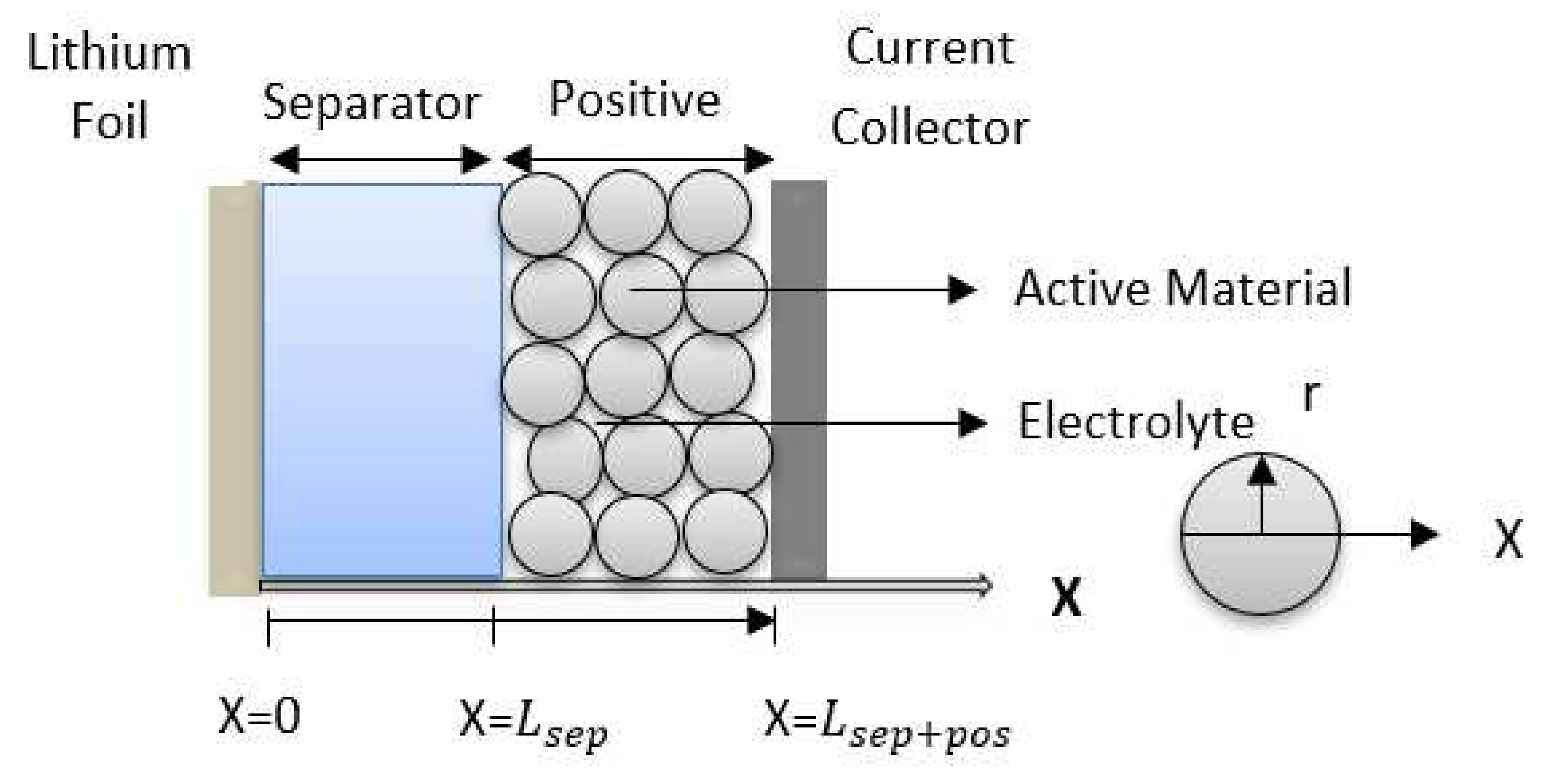
2.1. Half-Cell Made from a Single Cathode Active Material

The model considers one active material for the cathode, as seen in Figure 1. The negative electrode in the half-cell works as a reference electrode for the battery. For the modeling, we consider the: (a) electric charge transfer in the cathode; (b) ionic charge transfer in the cathode; (c) lithium-ion mass transfer in the cathode; (d) lithium mass transfer in the cathode active material particles (intercalation); (e) ionic charge transfer in the electrolyte; (f) lithium-ion mass transfer in the separator, and (g) electrochemical reaction at the active sites of the cathode. The modeling equations and their boundary and initial conditions are summarized in Table 1. Several assumptions have been made for the modeling. The main assumptions are that the battery is fresh and there is no sign of materials degradation, the cathode active materials are solid spheres with uniform size, the Bruggeman assumption is valid for calculation of the effective conductivities and diffusivities, there is no volume change in the cathode active materials during charging and discharging, no SEI layer is formed on the lithium foil, the entire surface of all cathode active material particles is an active site for electrochemical reactions, the voltage drop in the aluminum current collector is negligible, and the half-cell temperature is kept constant during charging and discharging. In addition, the half-cell model is pseudo-two-dimensional (1D + 1D). This means that the lithium mass transfer equation in the cathode active material particles is solved only in r direction, and all other transport equations are solved in only x direction. See Figure 1 for the r and x directions.

2.2. Half-Cell Made from a Mixture of Cathode Active Materials

The modeling of the cathode performance made from a mixture of cathode active materials (see Figure 2) is similar to the modeling of the cathode made from a single cathode active material. However, there are some differences. The differences are discussed here.
The mixture of cathode active materials consists of spherical particles from different active materials that are mixed homogenously before the cathode slurry is coated on the aluminum current collector. For the modeling, it is assumed that the mixture is homogeneous, while each type of cathode active material can have its own particle sizes. For the mixture of cathode active materials, the equation of lithium mass transfer should be solved for each cathode active material. The electrochemical reaction equation should also be solved separately for each cathode active material, and the total local current should be obtained from the summation of the local current generated by each cathode active material. The additional modeling equations and their boundary and initial conditions to simulate the behavior of a mixture of cathode active materials are summarized in Table 2.
The capacity of the cathode made from a mixture of cathode active materials can be obtained from Equation (2):
Q c a t = F ε s , c a t L p o s i = 1 N Y i c s , i , m a x S O C i , m a x S O C i , m i n  
where the state-of-charge (SOC) of each active material can be obtained from Equation (3):
S O C i = c s , i , s u r f c s , i , m a x  
Based on this mathematical modeling, the simulation of half-cell LIBs was carried out in the COMSOL Multiphysics software package, version 5.2a.

3. Experiment

3.1. Cathode Groups

The cathodes for the experiments are divided into three groups. The first group is the cathodes that were made of a single cathode active material to simulate the performance of the battery in case the separation of active materials during the recycling process is ideal. This group is for the study of scenario I. The second group is the cathodes that were made of a mixture of active materials with one dominant cathode active material to simulate the conditions that the separation process is not ideal and there are some impurities from other types of cathode active materials. This group is for the study of scenario II. The cathodes in this group are made from a dominant cathode active material and the minor percentage of the other four types of cathode active materials that are equally mixed. The third group is the cathodes that were made of the equally mixed five types of cathode active materials to simulate the battery performance in the case that no separation happened in the battery recycling. This group is for the study of scenario III.

3.2. Half-Cell Fabrication

To study the performance of cathodes, several cathodes from each of the three groups were made. The cathode active material was acetylene black (MTI corporation), and the binder was PVDF (MTI corporation). The cathode active materials were mixed homogenously with PVDF and acetylene black with a weight ratio of 92:4:4, respectively. The solvent to make the cathode slurry was NMP (Sigma-Aldrich) that was mixed at a solid-to-liquid ratio of 1:2 before the cathode slurry was coated on the aluminum current collector. After making the cathodes, several coin half-cells (3032-type) were assembled in the order shown in Figure 3 in an argon-filled glovebox in the laboratory. Lithium foil was used as a reference electrode for all half-cells. The electrolyte used in the half-cells was 1 M LiPF6 salt in 1:1 EC:DEC (by weight) solvent (Sigma-Aldrich).

4. Results and Discussion

In this section, the results of the computer simulation and experiments for scenarios I to III are presented. The results are generated based on one important assumption, that the efficiency of the regeneration process to recover the recycled cathode active materials is 100%. This means that the regeneration process is ideal and the capacity of the recycled active material after the regeneration reaches the capacity of the fresh material. This assumption was made to reduce the degree of freedom of the study to only focus on the effect of blending cathode materials on the cathode performance.

4.1. Scenario I

In this scenario, the separation process is assumed to be performed ideally. This means that a pure single regenerated cathode active material can be used to make new LIBs. The modeling was carried out for five of the most common cathode active materials: LCO, LMO, NCA, NMC, and LFP. The modeling parameters for each of the cathode active materials are listed in Table 3.
The open circuit voltage (OCV) profile of each cathode active material is shown in Figure 4. As seen, each material has a different nominal voltage. The OCV profile represents the ideal discharge performance of the half-cell.
The performance of half-cells with single cathode active materials at 1C discharge is shown in Figure 5. The actual capacity of the battery is lower than the theoretical capacity. The discrepancies of the actual and the theoretical capacity of cathode active materials are due to several factors. One of the factors is the discharge C-rate. As the C-rate increases, the capacity of the battery decreases [28]. In this study, we chose 1C because it is an appropriate indicator for the battery performance, especially for batteries used in hybrid electric vehicles and aircrafts. Another factor is the crystal structure of the active materials. As shown in Figure 5, the actual capacity of batteries, which is obtained from mathematical modeling, is in the range of the experimental results reported in the literature [29,30]. In addition, the modeling and experimental profiles are very close to each other, indicating the validity of the adopted mathematical model.

4.2. Scenario II

In this scenario, the separation process is performed with an efficiency of less than 100% (actual separation process). Therefore, the single regenerated cathode active material contains a little of the other types of cathode active materials.
To obtain the electrochemical performance of the half-cells made from these regenerated cathode active materials, pure LCO, LMO, NMC, NCA, and LFP powders were mixed homogenously in different mass ratios. Five different mass ratios of 90%, 80%, 70%, 60%, and 50% were considered for the dominant active materials, and 2.5%, 5%, 7.5%, 10%, and 12.5% of each of the other four active materials were mixed with the dominant material, respectively. For example, for the dominant LCO cathode, we mixed 90 wt% LCO with 2.5 wt% NMC, 2.5 wt% LMO, 2.5 wt% NCA, and 2.5 wt% LFP for sample cathode one. For sample cathode two, we mixed 80 wt% LCO with 5 wt% NMC, 5 wt% LMO, 5 wt% NCA, and 5 wt% LFP. Similarly, we made sample cathodes three, four, and five for the dominant LCO of 70%, 60%, and 50%. We also carried out the same for the dominant LMO, NMC, NCA, and LFP cathode samples one to five. Obviously, in each half-cell, the dominant cathode active material has a higher percentage than the other four cathode active materials. After preparation of all samples and finishing the formation process, the half-cells were discharged between the voltage limits of 4.2 V and 2.9 V at a 1C rate and 25 °C.
Figure 6 shows the performance of the half-cells for five cathode active materials. As seen, when the NCA is the dominant active material, the capacity of the battery decreased with the decreasing percentage of NCA. The reduction in the capacity is because of the higher capacity of NCA among the other four types of the cathode active materials. When the LCO and NMC are the dominant materials, there is a slight reduction in the capacity when the percentage of the dominant active material reduces. This insignificant reduction of the capacity happens because these two cathode materials have a capacity in the average range among the other cathode active materials.
When the dominant material is LMO, the capacity of the half-cells is increased with the decreasing percentage of LMO. This increase is due to the difference between the capacity of the LMO and the other four cathode active materials. In fact, LMO has the lowest capacity among the other four materials, while it has the highest nominal voltage of 3.9 V.
The worst-case scenario was found when the dominant material is LFP. The capacity of the half-cells decreased significantly. This reduction of the capacity is due to the fact that the LFP has the lowest nominal voltage (3.2 V) compared to the other four cathode materials, as seen in Figure 4. Thus, the performance of the cathode with a dominant active material is dependent on the nominal voltage of the other mixed active materials. Therefore, all other active materials should be completely separated from the LFP.
For validation purposes, we made half-cells with 60% of the dominant cathode active material and 10% of each of the other four active materials and compared the modeling results with the experimental results. This comparison is shown in Figure 6d. As seen, there is a good agreement between the experiments and modeling in terms of the prediction of the cathode capacity. However, discrepancies are evident for the prediction of voltages, especially for the case when LFP is the dominant active material. Since our focus in this paper is the evaluation of the electrode capacity, the current model is valid. However, a more accurate model is required for studying the voltage trends.

4.3. Scenario III

In this scenario, the separation has not been performed during the recycling process, all types of cathode active materials are regenerated together, and a mixture of cathode active materials is used to make new LIBs. Three samples were prepared for this scenario. For sample one, we made the half-cells from cathodes with equal weight percentages of the five cathode materials (20 wt% LCO, 20 wt% LMO, 20 wt% NMC, 20 wt% NCA, and 20 wt% LFP). Since from the results of scenario II we learned that LFP is not suitable to be in the mixture of cathode active materials, we made two more samples that have only 5 wt% and 0 wt% LFP. These two samples simulate the case that the separation is performed only for LFP. For sample two, we made the half-cells from cathodes with equal weight percentages of 23.75% for LCO, LMO, NMC, and NCA and 5 wt% LFP. For sample three, we made the half-cells from cathodes with equal weight percentages of 25% for LCO, LMO, NMC, and NCA. No LFP exists in sample three. The composition of samples one to three are listed in Table 4.
As seen in Figure 7, the best performance was found for the half-cells made from sample three, which has 0% LFP. The capacity of the half-cell made with a 5 wt% LFP (sample two) does not have noticeable a difference in comparison to the half-cell made from sample three. Therefore, we can conclude that a small fraction of LFP (typically less than 5 wt%) does not have a significant impact on the cathode capacity. However, the half-cell capacity decreases significantly when the weight percentage of LFP in the cathode active material mixture reaches 20% (sample one).

5. Conclusions

The performance of cathodes made from recycled cathode active materials for three scenarios of the active materials’ separation was studied. In scenario one, the separation process in the recycling facility was ideal, and a pure single cathode active material was used to make new batteries. In scenario two, the separation process for active materials in the recycling facility was realistic, with an efficiency of less than 100%. In this scenario, a single cathode active material that contains a little of the other types of cathode active materials was used to make new batteries. In scenario three, the separation was not performed, and all types of cathode active materials were regenerated together and used to make new batteries. The results were generated through modeling and computer simulation and several experiments were conducted for validation of the model. The cathode active materials that were studied are five commercially available cathode active materials: LMO, LCO, NMC, NCA, and LFP. The results indicated that the fabrication of new LIBs with a mixture of regenerated cathode active materials is possible when the cathode active materials are not separated from each other. However, it is better that the separation process is added to the recycling process, especially for minimization of the amount of LFP in the mixture of cathode active materials. It is not necessary that the separation process is ideal. However, more studies are still required to show that making new LIBs with a dominant cathode active material is technically and economically feasible.

Author Contributions

Conceptualization, S.F.; methodology, S.F.; software, H.A.-S.; validation, H.A.-S.; formal analysis, H.A.-S., and S.F.; investigation, H.A.-S., and S.F.; resources, S.F.; data curation, H.A.-S.; writing—original draft preparation, H.A.-S.; writing—review and editing, S.F.; visualization, H.A.-S.; supervision, S.F.; project administration, S.F.; funding acquisition, S.F. All authors have read and agreed to the published version of the manuscript.

Funding

This research received no external funding.

Acknowledgments

The authors gratefully acknowledge supports from the University of Akron and Al Jouf University.

Conflicts of Interest

The authors declare no conflict of interest.

Nomenclature

A Apparent surface area of electrode (m2)
cConcentration (mol/m3)
DDiffusivity ( m 2 / s )
D50Mean diameter of particles (m)
EeqEquilibrium potential (V)
fMean molar activity coefficient of inorganic salt in electrolyte
FFaraday’s constant (96,485 C/mol)
i Currant density (A/m2)
IappliedApplied current to battery (A)
i0Exchange currant density (A/m2)
ilocalLocal current density generation (A/m2)
kElectrochemical reaction rate coefficient (m/s)
LThickness (m)
NFlux (mol/m2·s)
QCapacity (Ah/m2)
rRadial direction in spherical coordinate system (m)
RUniversal gas constant (8.314 J/mol K)
rpAverage radius of active material particles
SaSurface area per unit volume (m2/m3)
SOCState of charge of the active material
ttime (s)
t + 0 Lithium-ion transference number
TTemperature (K)
xx direction in cartesian coordinate system (m)
YMole fraction of an active material in the mixture of active materials
Greek Letters
εVolume fraction
ηPolarization (V)
σConductivity (S/m)
ϕPotential (V)
Subscripts
0 Initial
iIndex for ith cathode active materials in the cathode mixture
lLiquid phase (electrolyte)
catCathode
effEffective
maxmaximum
minminimum
posPositive electrode (cathode)
refReference
sSolid phase of electrode (active/conductive material)
sepSeparator
surfSurface
Abbreviations
DEC Dimethyl carbonate
EC Ethylene carbonate
LCO LiCoO2
LFP LiFePO4
LIB Lithium-ion battery
LMO LiMn2O4
NCA LiNixCoyAl(1-x-y)O2
NMC LiNixCoyMn(1-x-y)O2
NMP N-Methyl-2-pyrrolidone
OCV Open circuit voltage
PVDF polyvinylidene fluoride

References

  1. Zubi, G.; Dufo-López, R.; Carvalho, M.; Pasaoglu, G. The lithium-ion battery: State of the art and future perspectives. Renew. Sustain. Energy Rev. 2018, 89, 292–308. [Google Scholar] [CrossRef]
  2. Lu, L.; Han, X.; Li, J.; Hua, J.; Ouyang, M. A review on the key issues for lithium-ion battery management in electric vehicles. J. Power Sources 2013, 226, 272–288. [Google Scholar] [CrossRef]
  3. Olivetti, E.A.; Ceder, G.; Gaustad, G.G.; Fu, X. Lithium-Ion Battery Supply Chain Considerations: Analysis of Potential Bottlenecks in Critical Metals. Joule 2017, 1, 229–243. [Google Scholar] [CrossRef] [Green Version]
  4. An, S.J.; Li, J.; Daniel, C.; Mohanty, D.; Nagpure, S.; Wood, D.L. The state of understanding of the lithium-ion-battery graphite solid electrolyte interphase (SEI) and its relationship to formation cycling. Carbon 2016, 105, 52–76. [Google Scholar] [CrossRef] [Green Version]
  5. Zhang, X.; Lu, C.; Peng, H.; Wang, X.; Zhang, Y.; Wang, Z.; Zhong, Y.; Wang, G. Influence of sintering temperature and graphene additives on the electrochemical performance of porous Li4Ti5O12 anode for lithium ion capacitor. Electrochim. Acta 2017, 246, 1237–1247. [Google Scholar] [CrossRef]
  6. Wu, B.; Wang, J.; Li, J.; Lin, W.; Hu, H.; Wang, F.; Zhao, S.; Gan, C.; Zhao, J. Morphology controllable synthesis and electrochemical performance of LiCoO2 for lithium-ion batteries. Electrochim. Acta 2016, 209, 315–322. [Google Scholar] [CrossRef]
  7. Fergus, J.W. Recent developments in cathode materials for lithium ion batteries. J. Power Sources 2010, 195, 939–954. [Google Scholar] [CrossRef]
  8. Plichta, E.; Behl, W. A low-temperature electrolyte for lithium and lithium-ion batteries. J. Power Sources 2000, 88, 192–196. [Google Scholar] [CrossRef]
  9. Chen, J.; Wang, S.; Ding, L.; Jiang, Y.; Wang, H. Performance of through-hole anodic aluminum oxide membrane as a separator for lithium-ion battery. J. Membr. Sci. 2014, 461, 22–27. [Google Scholar] [CrossRef]
  10. Arora, P.; Zhang, Z. Battery Separators. Chem. Rev. 2004, 104, 4419–4462. [Google Scholar] [CrossRef]
  11. Ritchie, A.; Howard, W. Recent developments and likely advances in lithium-ion batteries. J. Power Sources 2006, 162, 809–812. [Google Scholar] [CrossRef]
  12. de la Llave, E.; Talaie, E.; Levi, E.; Nayak, P.; Dixit, M.; Rao, P.T.; Hartmann, P.; Chesneau, F.; Major, D.; Greenstein, M.; et al. Improving Energy Density and Structural Stability of Manganese Oxide Cathodes for Na-Ion Batteries by Structural Lithium Substitution. Chem. Mater. 2016, 28, 9064–9076. [Google Scholar] [CrossRef]
  13. Albertus, P.; Christensen, J.; Newman, J. Experiments on and Modeling of Positive Electrodes with Multiple Active Materials for Lithium-Ion Batteries. J. Electrochem. Soc. 2009, 156, A606. [Google Scholar] [CrossRef]
  14. Jeong, S.K.; Shin, J.S.; Nahm, K.S.; Kumar, P.; Stephan, A.M. Electrochemical studies on cathode blends of LiMn2O4 and Li[Li1/15Ni1/5Co2/5Mn1/3O2]. Mater. Chem. Phys. 2008, 111, 213–217. [Google Scholar] [CrossRef]
  15. Jobst, N.M.; Hoffmann, A.; Klein, A.; Zink, S.; Wohlfahrt-Mehrens, M. Ternary Cathode Blend Electrodes for Environmentally Friendly Lithium-Ion Batteries. ChemSusChem 2020, 13, 3928–3936. [Google Scholar] [CrossRef]
  16. Al-Shammari, H.; Esmaeeli, R.; Aliniagerdroudbari, H.; Alhadri, M.; Hashemi, S.R.; Zarrin, H.; Farhad, S. Recycling lithium-ion battery: Mechanical separation of mixed cathode active materials. In ASME International Mechanical Engineering Congress and Exposition; Proceedings (IMECE); American Society of Mechanical Engineers (ASME): Salt Lake City, UT, USA, 2019. [Google Scholar] [CrossRef]
  17. Al-Shammari, H.; Farhad, S. Regeneration of Cathode Mixture Active Materials Obtained from Recycled Lithium Ion Batteries. SAE Technical Paper 2020-01-0864. 2020. Available online: https://www.sae.org/publications/technical-papers/content/2020-01-0864/ (accessed on 3 December 2021).
  18. Al-Shammari, H.; Farhad, S. Heavy liquids for rapid separation of cathode and anode active materials from recycled lithium-ion batteries. Resour. Conserv. Recycl. 2021, 174, 105749. [Google Scholar] [CrossRef]
  19. Kay, I.; Esmaeeli, R.; Hashemi, S.R.; Mahajan, A.; Farhad, S. Recycling Li-ion batteries: Robot disassembly of electric vehicle battery systems. In Proceedings of the ASME 2019, Internal Mechanical Engineering Congress and Exposition (IMECE), Salt Lake City, UT, USA, 8–14 November 2019. [Google Scholar] [CrossRef]
  20. Doyle, M.; Newman, J. The use of mathematical modeling in the design of lithium/polymer battery systems. Electrochim. Acta 1995, 40, 2191–2196. [Google Scholar] [CrossRef]
  21. Chabot, V.; Farhad, S.; Chen, Z.; Fung, A.S.; Yu, A.; Hamdullahpur, F. Effect of electrode physical and chemical properties on lithium-ion battery performance. Int. J. Energy Res. 2013, 37, 1723–1736. [Google Scholar] [CrossRef]
  22. Liu, C.; Li, H.; Kong, X.; Zhao, J. Modeling analysis of the effect of battery design on internal short circuit hazard in LiNi0.8Co0.1Mn0.1O2/SiOx-graphite lithium ion batteries. Int. J. Heat Mass Transf. 2020, 153, 119590. [Google Scholar] [CrossRef]
  23. Miranda, D.; Gören, A.; Costa, C.; Silva, M.; Almeida, A.; Lanceros-Mendez, S. Theoretical simulation of the optimal relation between active material, binder and conductive additive for lithium-ion battery cathodes. Energy 2019, 172, 68–78. [Google Scholar] [CrossRef]
  24. Ramadass, P.; Haran, B.; White, R.; Popov, B.N. Mathematical modeling of the capacity fade of Li-ion cells. J. Power Sources 2003, 123, 230–240. [Google Scholar] [CrossRef]
  25. Farhad, S.; Nazari, A. Introducing the energy efficiency map of lithium-ion batteries. Int. J. Energy Res. 2019, 43, 931–944. [Google Scholar] [CrossRef]
  26. Paul, N.; Keil, J.; Kindermann, F.M.; Schebesta, S.; Dolotko, O.; Mühlbauer, M.J.; Kraft, L.; Erhard, S.; Jossen, A.; Gilles, R. Aging in 18650-type Li-ion cells examined with neutron diffraction, electrochemical analysis and physico-chemical modeling. J. Energy Storage 2018, 17, 383–394. [Google Scholar] [CrossRef]
  27. Dong, T.; Peng, P.; Jiang, F. Numerical modeling and analysis of the thermal behavior of NCM lithium-ion batteries subjected to very high C-rate discharge/charge operations. Int. J. Heat Mass Transf. 2018, 117, 261–272. [Google Scholar] [CrossRef]
  28. Tang, W.; Liu, L.; Tian, S.; Li, L.; Yue, Y.; Wu, Y.; Guan, S.; Zhu, K. Nano-LiCoO2 as cathode material of large capacity and high rate capability for aqueous rechargeable lithium batteries. Electrochem. Commun. 2010, 12, 1524–1526. [Google Scholar] [CrossRef]
  29. Qiu, L.; Shao, Z.; Wang, D.; Wang, W.; Wang, F.; Wang, J. Enhanced electrochemical properties of LiFePO4 (LFP) cathode using the carboxymethyl cellulose lithium (CMC-Li) as novel binder in lithium-ion battery. Carbohydr. Polym. 2014, 111, 588–591. [Google Scholar] [CrossRef]
  30. Nishi, Y. Lithium ion secondary batteries; past 10 years and the future. J. Power Sources 2001, 100, 101–106. [Google Scholar] [CrossRef]
Figure 1. Schematic of the half-cell lithium-ion battery made from a single cathode active material.
Energies 15 00410 g001
Figure 2. Schematic of the half-cell lithium-ion battery made from a mixture of cathode active materials.
Energies 15 00410 g002
Figure 3. The schematic of the half-cell assembly of coin cells in glovebox.
Energies 15 00410 g003
Figure 4. Open circuit voltage of some commercially available cathode active materials for LIBs versus the active material’s state of charge at 25 °C.
Energies 15 00410 g004
Figure 5. Discharge profile (1C and 25 °C) of half-cells made from cathodes with a single cathode active material.
Energies 15 00410 g005
Figure 6. Discharge profile (1C and 25 °C) of half-cells made from a dominant cathode active material. (a) 90% dominant active material mixed with 10% other active materials (2.5% each), (b) 80% dominant active material mixed with 20% other active materials (5% each), (c) 70% dominant active material mixed with 30% other active materials (7.5% each), (d) 60% dominant active material mixed with 40% other active materials (10% each), and (e) 50% dominant active material mixed with 50% other active materials (12.5% each).
Energies 15 00410 g006aEnergies 15 00410 g006bEnergies 15 00410 g006c
Figure 7. Discharge profile (1C, 25 °C) of cathodes made from the mixture of regenerated cathode active materials. Black curves: 20 wt% of each of the five types of cathode active materials (sample 1). Red curves: 5 wt% LFP and 23.75 wt% of each of the other four active materials (sample 2). Blue curves: 0 wt% LFP and 25 wt% of each of the other four cathode active materials (sample 3).
Energies 15 00410 g007
Table 1. The modeling equations for performance simulation of a cathode made from a single active material [20].
EquationsInitial and Boundary Conditions
Li mass transfer in cathode active material particles
c s t = 1 r 2 r r 2 D s c s r
Solution of this equation gives the distribution of lithium in r direction in the cathode particle, which is located at any x, at any time t
c s r = 0   a t   r = 0
c s r = i l o c a l F D s   a t   r = r p
c s = c s , 0   a t   t = 0
Electric charge transfer in the cathode
. i s = S a , c a t i l o c a l
i s = σ s , c a t , e f f ϕ s
σ s , c a t , e f f = σ s , c a t ε s , c a t 1.5
S a , c a t = 3 r p , c a t
Solutions of these equations give the distribution of electric current along the cathode thickness at any time t
i s = 0   a t   x = L s e p
ϕ s = 0   a t   x = L s e p
i s = I a p p l i e d A a t   x = L s e p + L p o s
Ionic charge transfer in the electrolyte within the cathode
. i l = S a i l o c a l
i l = σ l , c a t , e f f ϕ l + 2 R T F σ l , c a t , e f f 1 t + 0 1 + d ln f d ln c l ln c l
σ l , c a t , e f f = σ l ε l , c a t 1.5
Solutions of these equations give the distribution of ionic current along the cathode thickness at any time t
i l = 0   a t   x = L s e p + L p o s
i l = I a p p l i e d A a t   x = L s e p
Li+ mass transfer in the electrolyte within the cathode
ε l , c a t c l t + . N l = 0
N l = D l , c a t , e f f c l i l t + 0 F
D l , c a t , e f f = D l ε l , c a t 1.5
Solutions of these equations give the distribution of lithium-ion concentration along the cathode thickness at any time t
N l = 0   a t   x = L s e p + L p o s
c l = c l , 0   a t   t = 0
Ionic charge transfer in the electrolyte within the separator
. i l = 0
i l = σ l , s e p , e f f ϕ l + 2 R T F σ l , s e p , e f f 1 t + 0 1 + d ln f d ln c l ln c l
σ l , s e p , e f f = σ l ε l , s e p 1.5
Solutions of these equations give the distribution of ionic current along the separator thickness at any time t
i l = I a p p l i e d A a t   x = 0
Li+ mass transfer in the electrolyte within the separator
ε l , s e p c l t + . N l = 0
N l = D l , s e p , e f f c l i l t + 0 F
D l , s e p , e f f = D l ε l , s e p 1.5
Solutions of these equations give the distribution of lithium-ion concentration along the separator thickness at any time t
N l = 0   a t   x = 0
c l = c l , 0   a t   t = 0
Electrochemical reaction in the cathode (Butler–Volmer kinetics)
i l o c a l , c a t = i 0 , c a t e x p F 2 R T η c a t e x p F 2 R T η c a t
i 0 , c a t = F k c a t c s , m a x c s , s u r f 0.5 c s , s u r f 0.5 C l C l , r e f 0.5
η c a t = ϕ s ϕ l E e q , c a t
Solutions of these equations give the local current generation along the cathode thickness at any time t as well as the local activation + concentration polarizations along the cathode thickness at any time t
Table 2. The additional modeling equations required for performance simulation of a cathode made from a mixture of active materials [13].
EquationsInitial and Boundary Conditions
Li mass transfer in the particles of each cathode active material
c s , i t = 1 r 2 r r 2 D s , i c s , i r         for   i t h   cathode   active   material
Solution of this equation gives the distribution of lithium in r direction in the particles of the cathode active material i, which is located at any x, at any time t
c s , i r = 0   a t   r = 0
c s , i r = i l o c a l , i F D s , i   a t   r = r p , i
c s , i = c s , i , 0   a t   t = 0
Electrochemical reaction in the cathode (Butler–Volmer kinetics)
i l o c a l , c a t , i = i 0 , c a t , i e x p F 2 R T η c a t , i e x p F 2 R T η c a t , i         for   i t h   cathode   active   material  
i 0 , c a t , i = F k c a t , i c s , i , m a x c s , i , s u r f 0.5 c s , i , s u r f 0.5 C l C l , r e f 0.5
η c a t , i = ϕ s ϕ l E e q , c a t , i
i l o c , t o t a l = i = 1 N i l o c , i
Solutions of these equations give the total local current generation along the cathode thickness at any time t as well as the local activation + concentration polarizations for each cathode active material along the cathode thickness at any time t
Table 3. Model parameters of the commonly used cathode active materials in LIBs [22,23,24,25,26,27].
Active MaterialDensity (kg/m3)D50
(μm)
Maximum State of Charge
(mol/m3)
Initial State of Charge
(mol/m3)
Reaction Rate COEFFICIENT, ki
( mol / s . m 2 )
Theoretical Capacity
(mAh/g)
LMO42802523,670.660005 × 10−10148.2
LCO50501251,55523,7501 × 10−7273.8
NMC477010.551,38521,5001 × 10−11279.5
NCA445013.646,3198067.91 × 10−10278.9
LFP36003.522,80610003.63 × 10−11169.9
Table 4. Mass fraction of active materials in the cathode samples made for scenario III.
Cathode in the Half-CellsLCO wt%LMO wt%NMC wt%NCA wt%LFP wt%
Sample 1 (20% each)2020202020
Sample 2 (5% LFP, 23.75% each)23.7523.7523.7523.755
Sample 3 (0% LFP, 25% each)252525250
Publisher’s Note: MDPI stays neutral with regard to jurisdictional claims in published maps and institutional affiliations.

