
A Fast Power Calculation Algorithm for Three-Phase Droop-Controlled-Inverters Using Combined SOGI Filters and Considering Nonlinear Loads

 , , ,
, , ,  and
and 
Abstract
:1. Introduction
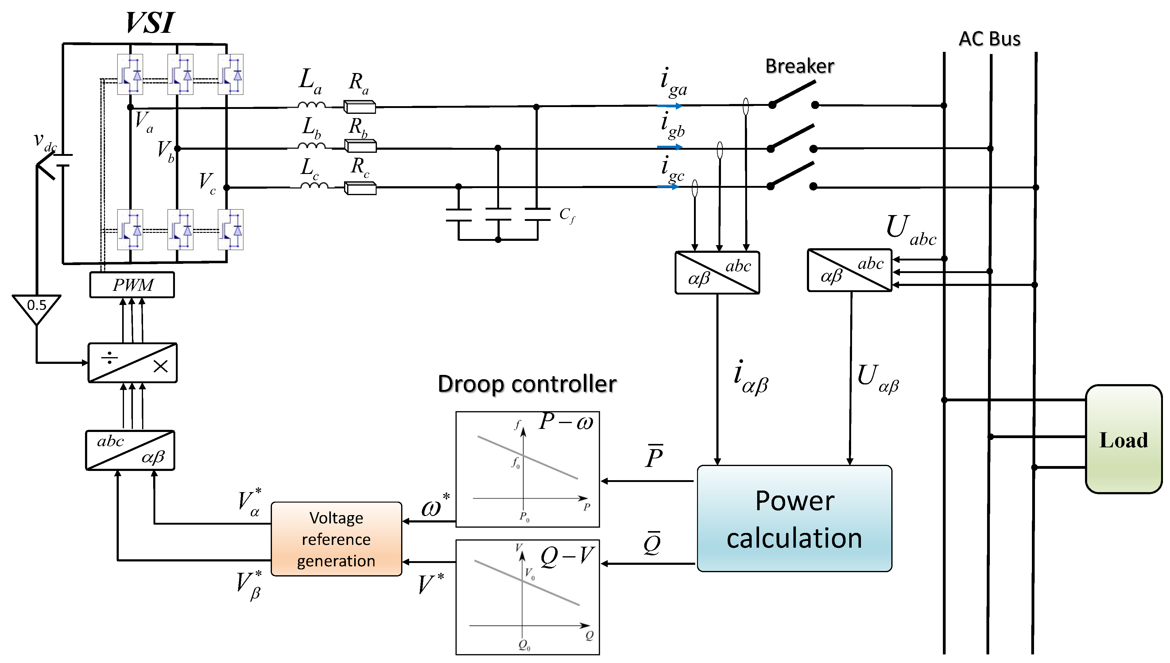
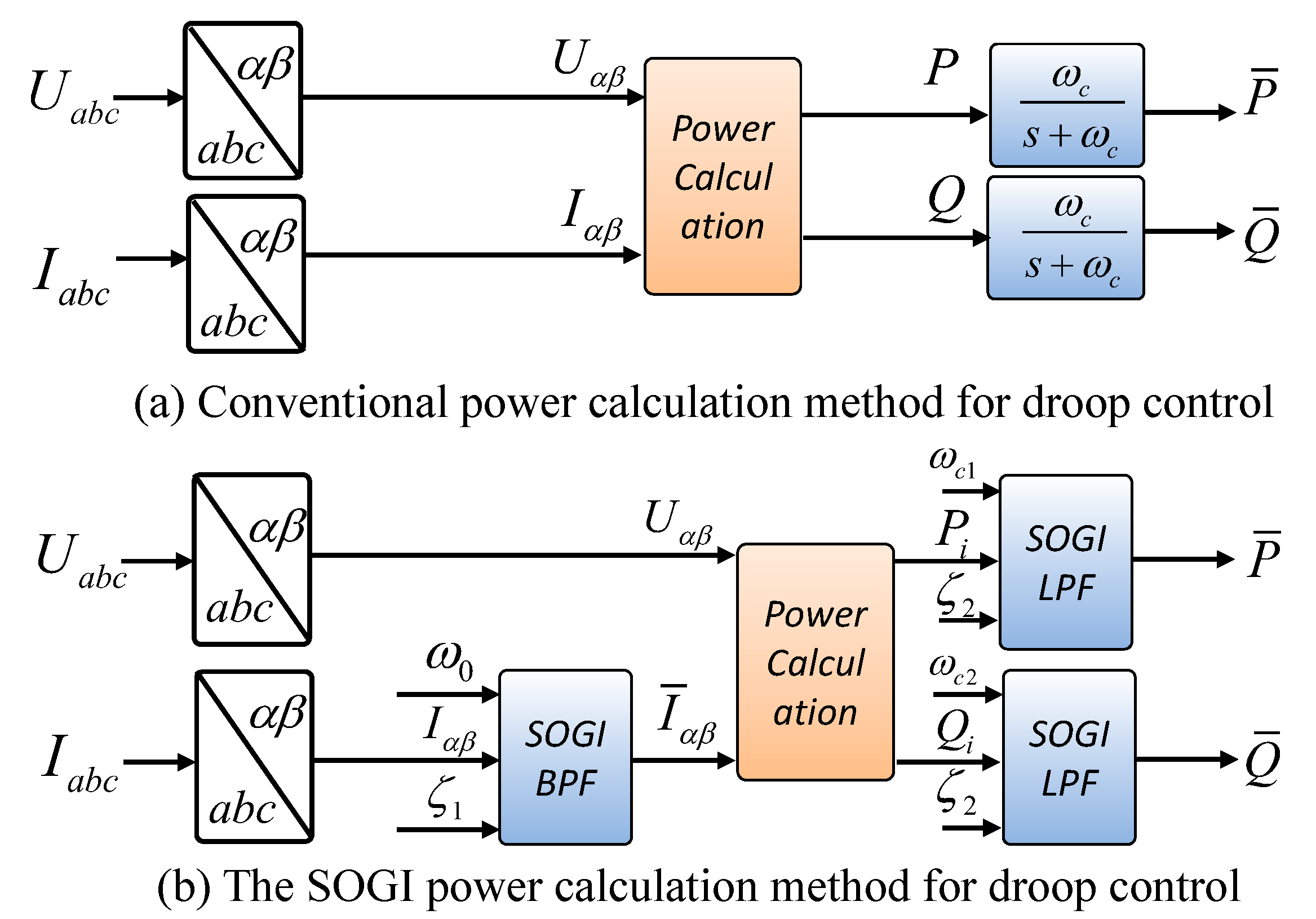
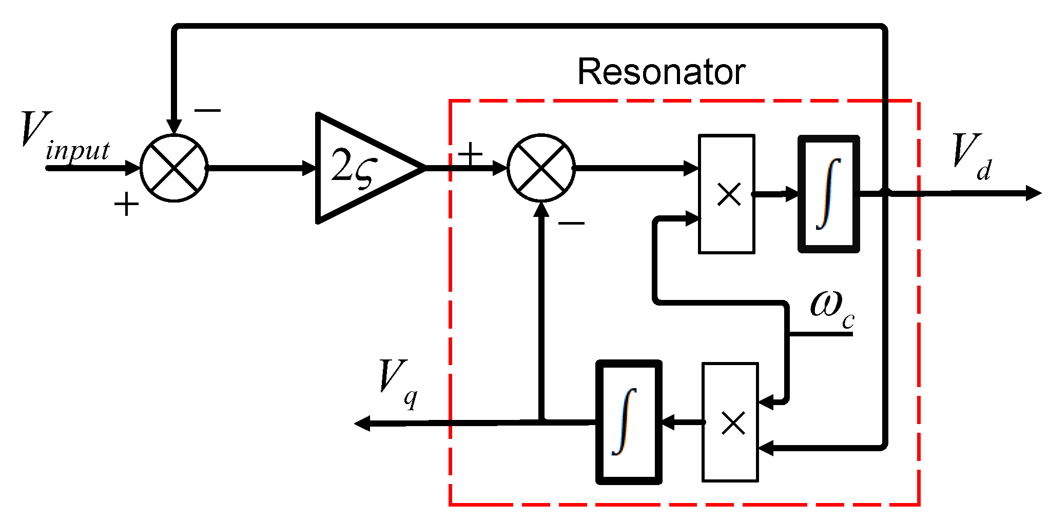
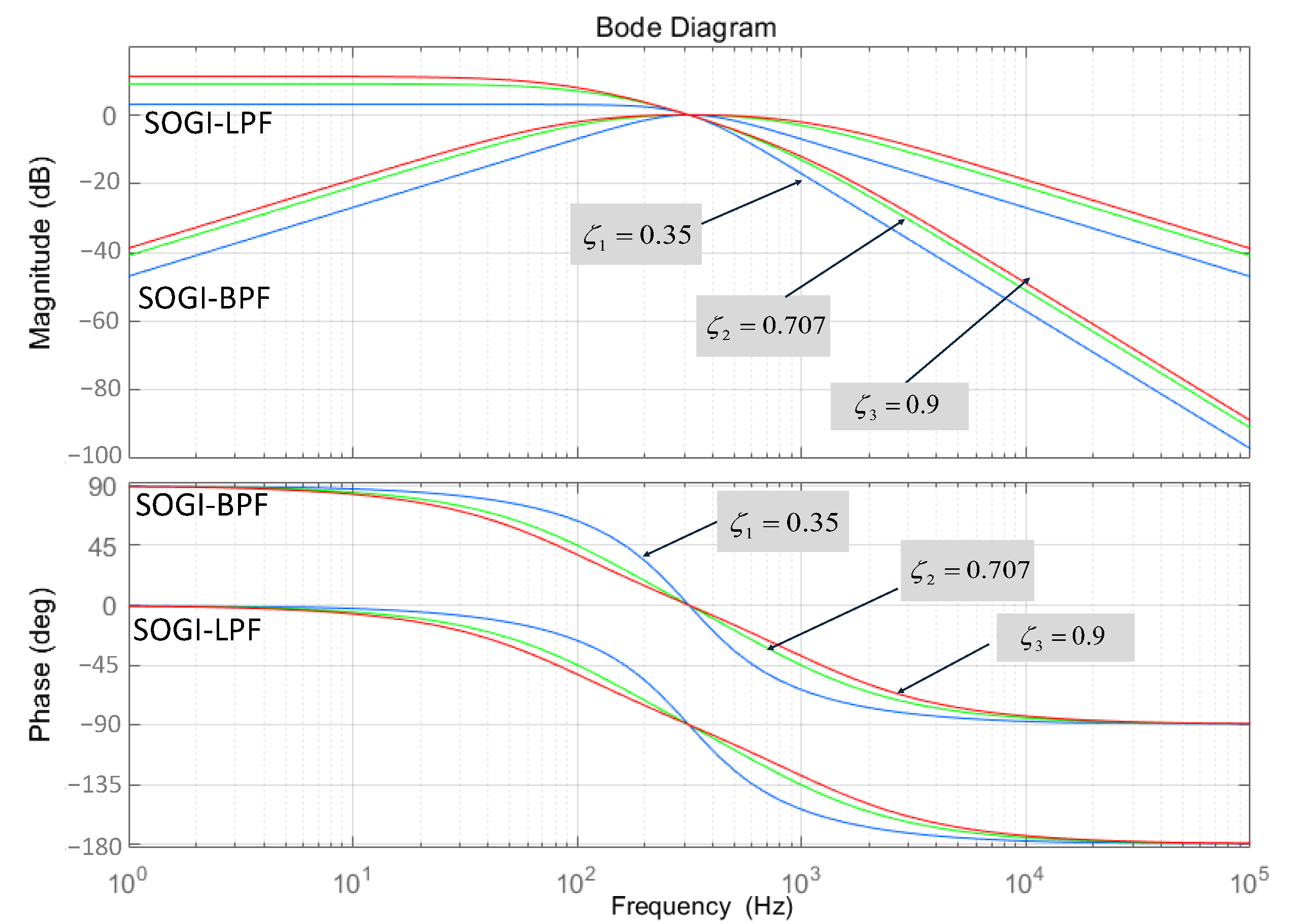
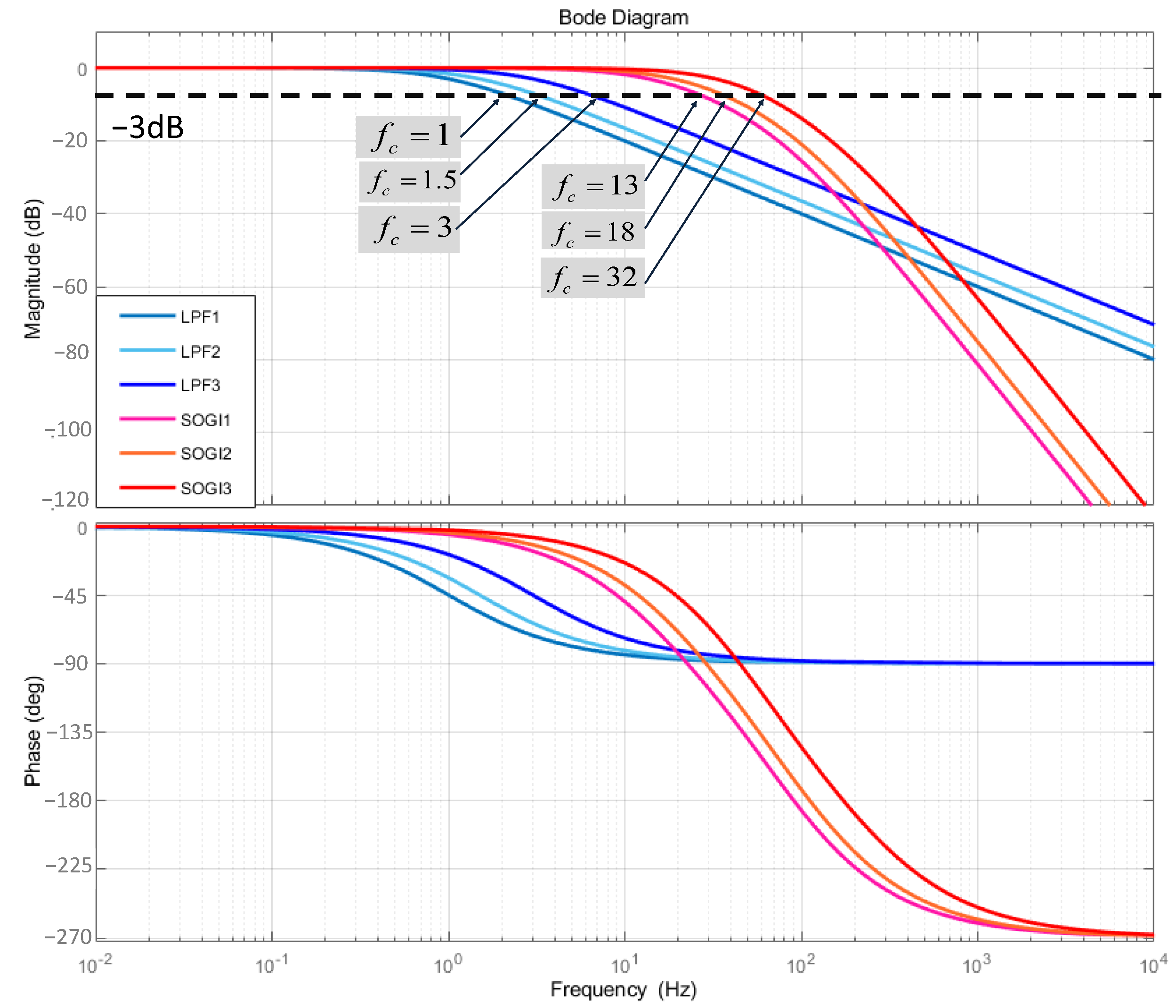
2. Combined SOGI Power Calculation Method
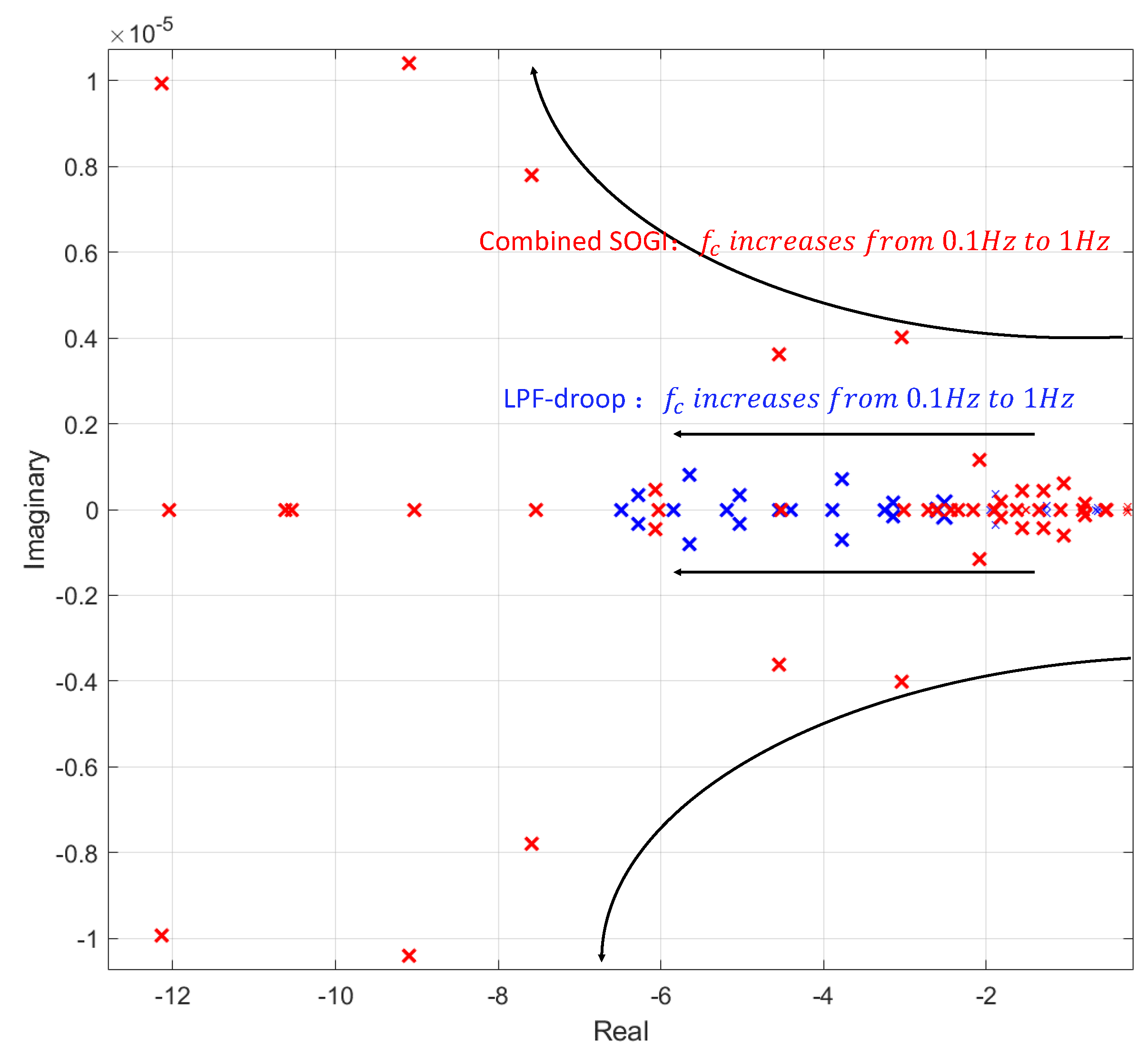
3. Small Signal Analysis
4. Simulation and HIL Validation
4.1. Simulation Results
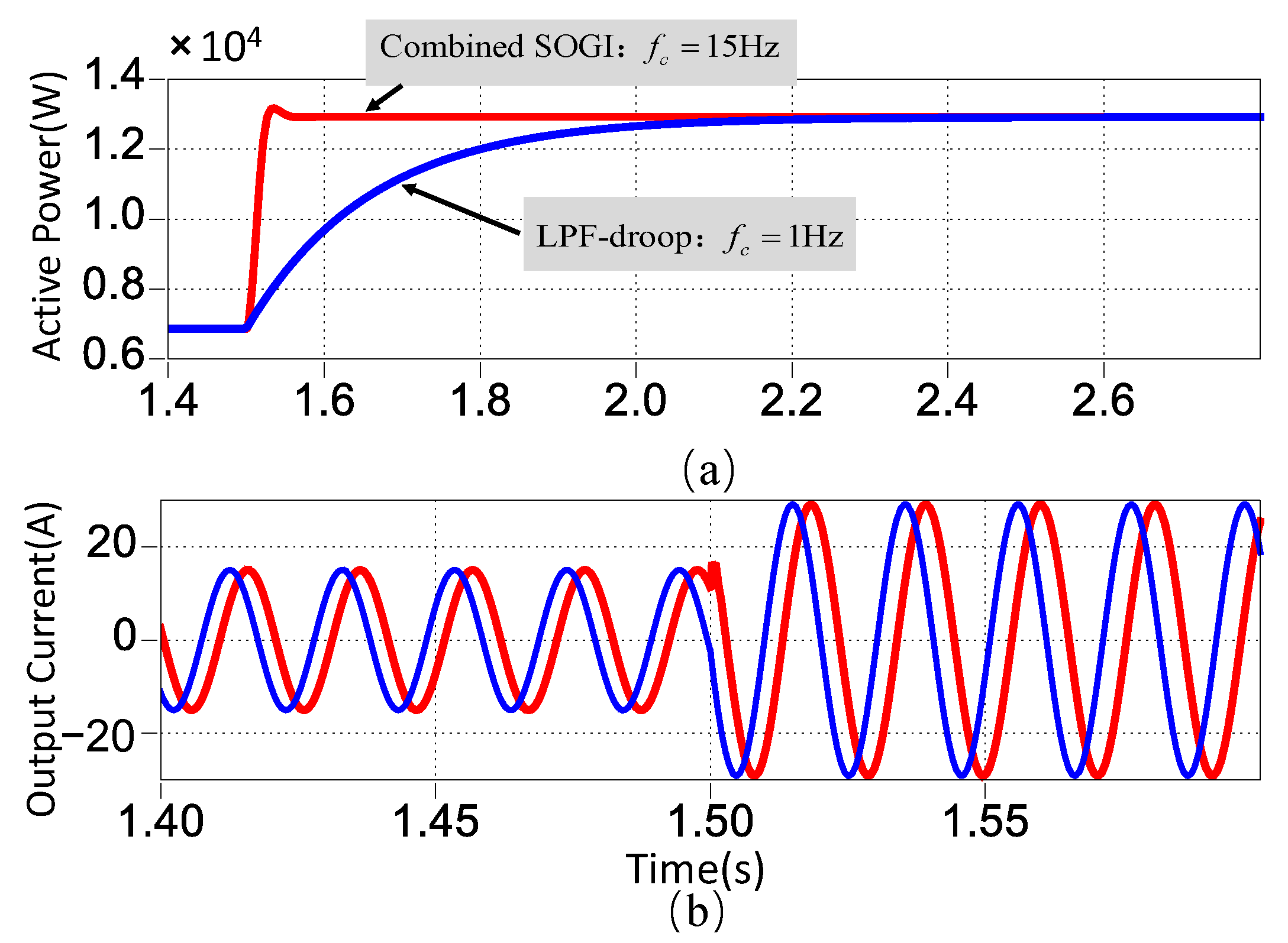
4.1.1. Case Study I: A Linear Load Step Change
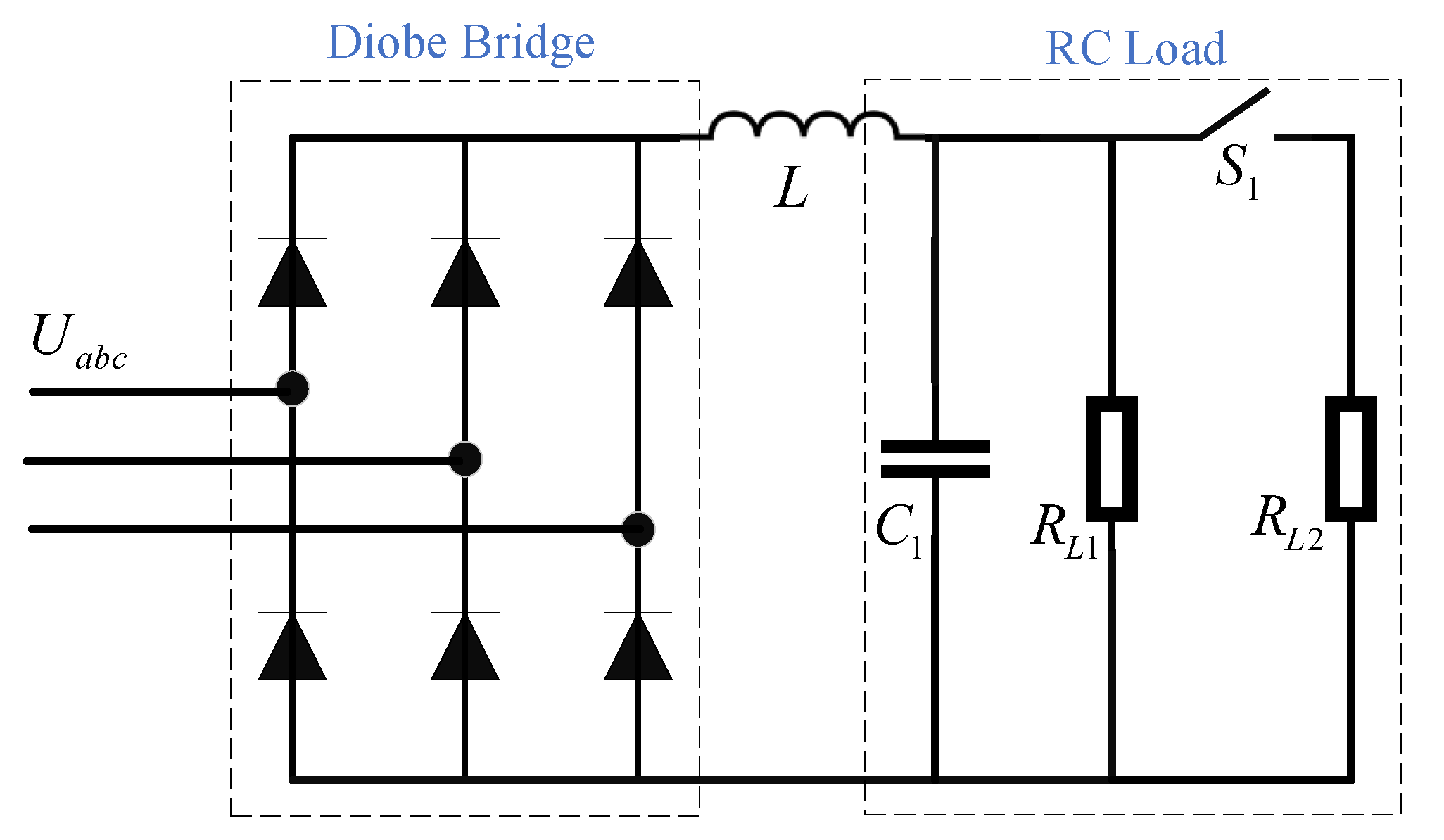
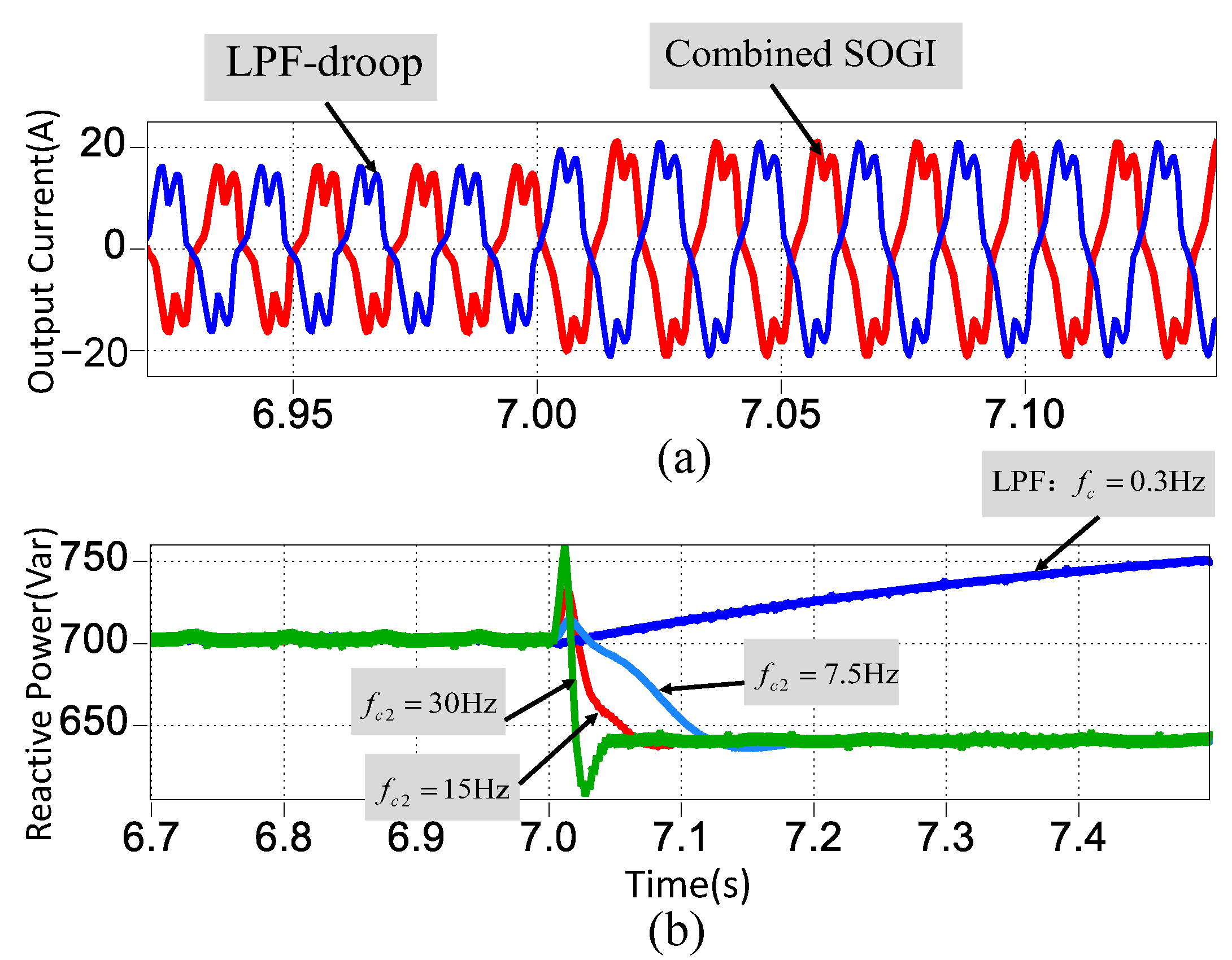
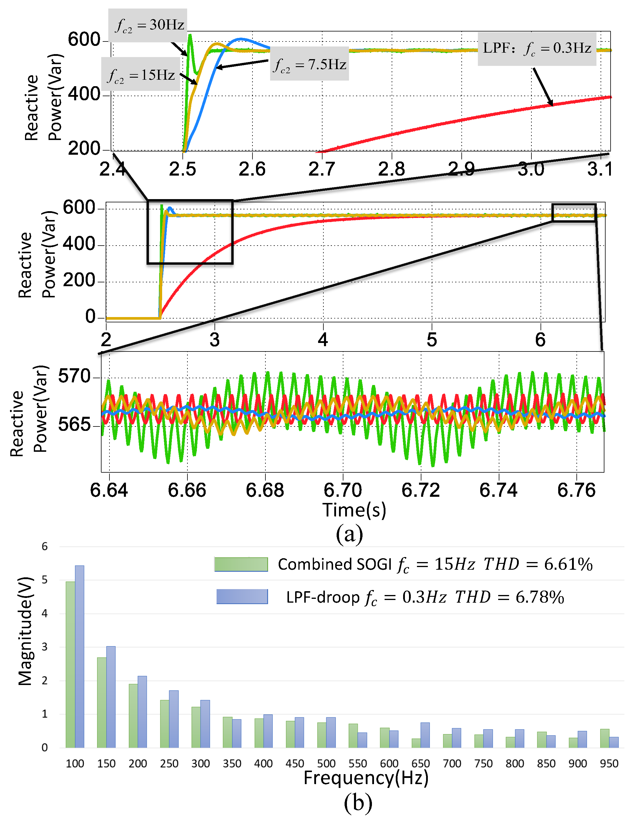
4.1.2. Case Study II: Variation Considering a Nonlinear RC Load
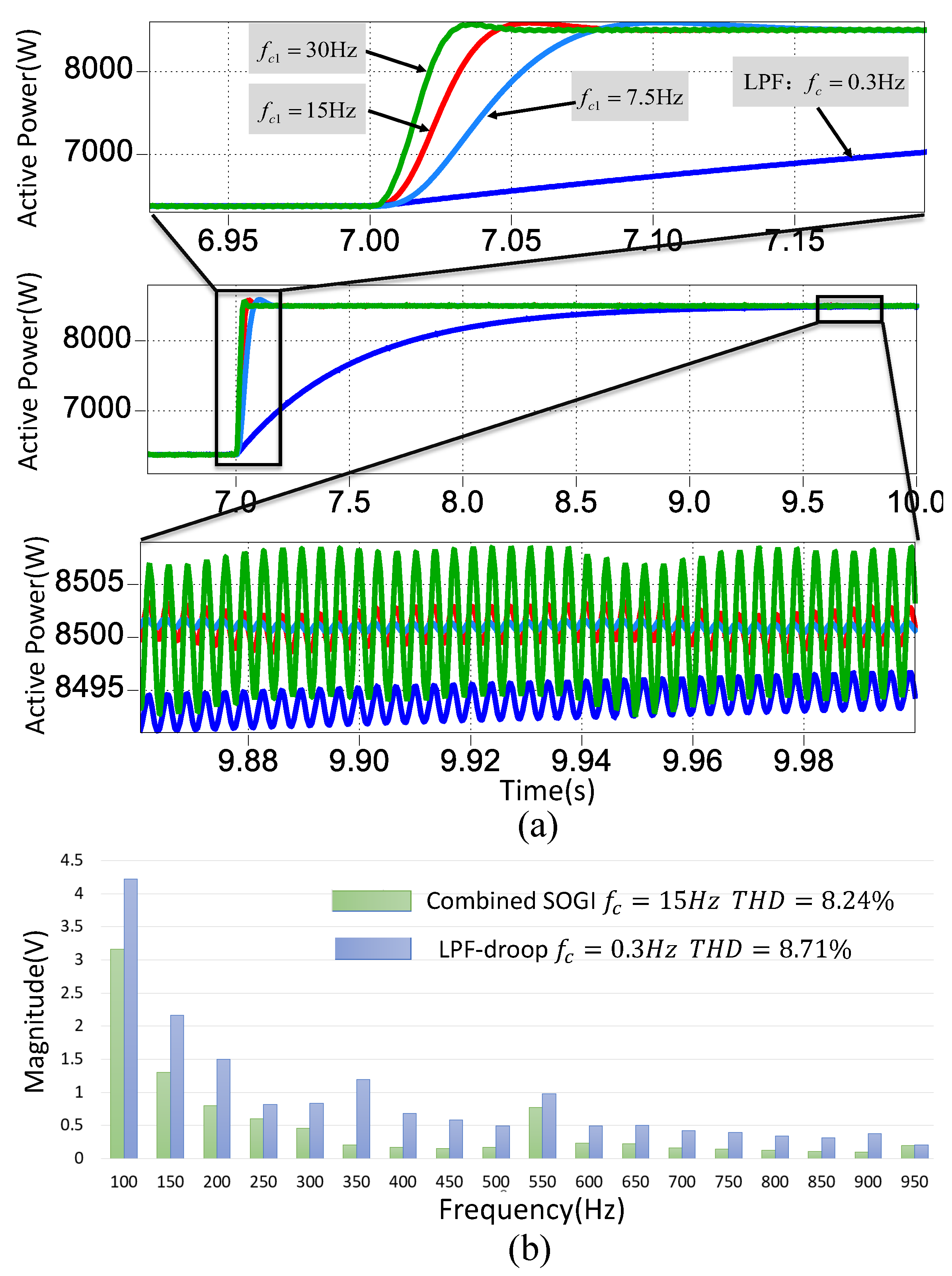
4.1.3. Case Study III: Variation Considering a Nonlinear RL Load
4.1.4. Case Study IV: Variation Considering a Nonlinear RC Load
4.2. HIL Assessment Results
5. Conclusions
Author Contributions
Funding
Data Availability Statement
Conflicts of Interest
References
- Shayeghi, H.; Shahryari, E.; Moradzadeh, M.; Siano, P. A survey on microgrid energy management considering flexible energy sources. Energies 2019, 12, 2156. [Google Scholar] [CrossRef] [Green Version]
- Hossain, M.A.; Pota, H.R.; Issa, W.; Hossain, M.J. Overview of AC microgrid controls with inverter-interfaced generations. Energies 2017, 10, 1300. [Google Scholar] [CrossRef]
- Jiayi, H.; Chuanwen, J.; Rong, X. A review on distributed energy resources and MicroGrid. Renew. Sustain. Energy Rev. 2008, 12, 2472–2483. [Google Scholar] [CrossRef]
- Olivares, D.E.; Mehrizi-Sani, A.; Etemadi, A.H.; Cañizares, C.A.; Iravani, R.; Kazerani, M.; Hajimiragha, A.H.; Gomis-Bellmunt, O.; Saeedifard, M.; Palma-Behnke, R.; et al. Trends in microgrid control. IEEE Trans. Smart Grid 2014, 5, 1905–1919. [Google Scholar] [CrossRef]
- Borup, U.; Blaabjerg, F.; Enjeti, P.N. Sharing of nonlinear load in parallel-connected three-phase converters. IEEE Trans. Ind. Appl. 2001, 37, 1817–1823. [Google Scholar] [CrossRef]
- De, D.; Ramanarayanan, V. Decentralized parallel operation of inverters sharing unbalanced and nonlinear loads. IEEE Trans. Power Electron. 2010, 25, 3015–3025. [Google Scholar] [CrossRef]
- De Brabandere, K.; Bolsens, B.; Van den Keybus, J.; Woyte, A.; Driesen, J.; Belmans, R. A voltage and frequency droop control method for parallel inverters. IEEE Trans. Power Electron. 2007, 22, 1107–1115. [Google Scholar] [CrossRef]
- Nasirian, V.; Davoudi, A.; Lewis, F.L.; Guerrero, J.M. Distributed adaptive droop control for DC distribution systems. IEEE Trans. Energy Convers. 2014, 29, 944–956. [Google Scholar] [CrossRef] [Green Version]
- Vasquez, J.C.; Guerrero, J.M.; Luna, A.; Rodríguez, P.; Teodorescu, R. Adaptive droop control applied to voltage-source inverters operating in grid-connected and islanded modes. IEEE Trans. Ind. Electron. 2009, 56, 4088–4096. [Google Scholar] [CrossRef]
- Deng, W.; Dai, N.; Lao, K.W.; Guerrero, J.M. A virtual-impedance droop control for accurate active power control and reactive power sharing using capacitive-coupling inverters. IEEE Trans. Ind. Appl. 2020, 56, 6722–6733. [Google Scholar] [CrossRef]
- Li, Z.; Chan, K.W.; Hu, J.; Guerrero, J.M. Adaptive droop control using adaptive virtual impedance for microgrids with variable PV outputs and load demands. IEEE Trans. Ind. Electron. 2020, 68, 9630–9640. [Google Scholar] [CrossRef]
- Zhang, W.; Zheng, Z.; Liu, H. A novel droop control method to achieve maximum power output of photovoltaic for parallel inverter system. CSEE J. Power Energy Syst. 2021. early access. [Google Scholar]
- Lu, F.; Liu, H. An Accurate Power Flow Method for Microgrids with Conventional Droop Control. Energies 2022, 15, 5841. [Google Scholar] [CrossRef]
- Buraimoh, E.; Aluko, A.O.; Oni, O.E.; Davidson, I.E. Decentralized Virtual Impedance-Conventional Droop Control for Power Sharing for Inverter-Based Distributed Energy Resources of a Microgrid. Energies 2022, 15, 4439. [Google Scholar] [CrossRef]
- Coelho, E.A.A.; Cortizo, P.C.; Garcia, P.F.D. Small-signal stability for parallel-connected inverters in stand-alone AC supply systems. IEEE Trans. Ind. Appl. 2002, 38, 533–542. [Google Scholar] [CrossRef]
- Vasquez, J.C.; Mastromauro, R.A.; Guerrero, J.M.; Liserre, M. Voltage support provided by a droop-controlled multifunctional inverter. IEEE Trans. Ind. Electron. 2009, 56, 4510–4519. [Google Scholar] [CrossRef]
- Wang, W.; Zeng, X.; Tang, X.; Tang, C. Analysis of microgrid inverter droop controller with virtual output impedance under non-linear load condition. IET Power Electron. 2014, 7, 1547–1556. [Google Scholar] [CrossRef]
- An, R.; Liu, J.; Wu, T.; Wang, S.; Liu, B. Analysis and design of cutoff frequency for power calculation low-pass filters in droop control. In Proceedings of the 2017 IEEE 3rd International Future Energy Electronics Conference and ECCE Asia (IFEEC 2017-ECCE Asia), Kaohsiung, Taiwan, 3–7 June 2017; pp. 1596–1600. [Google Scholar]
- Baghaee, H.R.; Mirsalim, M.; Gharehpetian, G.B. Power calculation using RBF neural networks to improve power sharing of hierarchical control scheme in multi-DER microgrids. IEEE J. Emerg. Sel. Top. Power Electron. 2016, 4, 1217–1225. [Google Scholar] [CrossRef]
- Matas, J.; Martin, H.; de la Hoz, J.; Abusorrah, A.; Al-Turki, Y.A.; Al-Hindawi, M. A family of gradient descent grid frequency estimators for the SOGI filter. IEEE Trans. Power Electron. 2017, 33, 5796–5810. [Google Scholar] [CrossRef]
- Matas, J.; Martín, H.; de la Hoz, J.; Abusorrah, A.; Al-Turki, Y.; Alshaeikh, H. A new THD measurement method with small computational burden using a SOGI-FLL grid monitoring system. IEEE Trans. Power Electron. 2019, 35, 5797–5811. [Google Scholar] [CrossRef]
- Alcala, J.M.; Castilla, M.; De Vicuña, L.G.; Miret, J.; Vasquez, J.C. Virtual impedance loop for droop-controlled single-phase parallel inverters using a second-order general-integrator scheme. IEEE Trans. Power Electron. 2010, 25, 2993–3002. [Google Scholar]
- Tolani, S.; Sensarma, P. An improved droop controller for parallel operation of single-phase inverters using RC output impedance. In Proceedings of the 2012 IEEE International Conference on Power Electronics, Drives and Energy Systems (PEDES), Bengaluru, India, 16–19 December 2012; pp. 1–6. [Google Scholar]
- El Mariachet, J.; Guan, Y.; Matas, J.; Martín, H.; Li, M.; Guerrero, J.M. HIL-assessed fast and accurate single-phase power calculation algorithm for voltage source inverters supplying to high total demand distortion nonlinear loads. Electronics 2020, 9, 1643. [Google Scholar] [CrossRef]
- El Mariachet, J.; Matas, J.; Martín, H.; Li, M.; Guan, Y.; Guerrero, J.M. A power calculation algorithm for single-phase droop-operated-inverters considering linear and nonlinear loads HIL-assessed. Electronics 2019, 8, 1366. [Google Scholar] [CrossRef]
- Wallace, I. Key Changes and Differences between the New IEEE 519-2014 Standard and IEEE 519-1992. Alcatel Telecommun. Rev. 2014, 1. [Google Scholar]
- Rodriguez, F.; Bueno, E.; Aredes, M.; Rolim, L.; Neves, F.A.; Cavalcanti, M.C. Discrete-time implementation of second order generalized integrators for grid converters. In Proceedings of the 2008 34th Annual Conference of IEEE Industrial Electronics, Orlando, FL, USA, 10–13 November 2008; pp. 176–181. [Google Scholar]


| Paremeters | Value |
|---|---|
| Nominal output voltage | 220 V |
| Nominal frequency | 50 Hz |
| L-type filter | 0.1 + 2 mH |
| Transmission line | 0.01 + 0.32 mH |
| SOGI-LPF damping coefficient | 0.707 |
| Active power droop coefficient m | 0.001 |
| Reactive power droop coefficient n | 0.0001 |
| THD of | THD of | Settling Time/% Reduction | |
|---|---|---|---|
| LPF-droop Hz | 0.932% | 8.71% | 2.15 s/- |
| Combined SOGI Hz | 1.331% | 9.05% | 0.078 s/96.37% |
| Combined SOGI Hz | 0.941% | 8.24% | 0.096 s/95.5% |
| Combined SOGI Hz | 0.587% | 7.74% | 0.162 s/92.5% |
| THD of | THD of | Settling Time/% Reduction | |
|---|---|---|---|
| LPF-droop Hz | 0.621% | 6.78% | 2.84 s/- |
| Combined SOGI Hz | 0.894% | 6.98% | 0.064 s/97.7% |
| Combined SOGI Hz | 0.614% | 6.61% | 0.076 s/97.3% |
| Combined SOGI Hz | 0.443% | 6.36% | 0.124 s/95.6% |
Publisher’s Note: MDPI stays neutral with regard to jurisdictional claims in published maps and institutional affiliations. |
© 2022 by the authors. Licensee MDPI, Basel, Switzerland. This article is an open access article distributed under the terms and conditions of the Creative Commons Attribution (CC BY) license (https://creativecommons.org/licenses/by/4.0/).
Share and Cite
Li, M.; Matas, J.; Mariachet, J.E.; Branco, C.G.C.; Guerrero, J.M. A Fast Power Calculation Algorithm for Three-Phase Droop-Controlled-Inverters Using Combined SOGI Filters and Considering Nonlinear Loads. Energies 2022, 15, 7360. https://doi.org/10.3390/en15197360
Li M, Matas J, Mariachet JE, Branco CGC, Guerrero JM. A Fast Power Calculation Algorithm for Three-Phase Droop-Controlled-Inverters Using Combined SOGI Filters and Considering Nonlinear Loads. Energies. 2022; 15(19):7360. https://doi.org/10.3390/en15197360
Chicago/Turabian StyleLi, Mingshen, Jose Matas, Jorge El Mariachet, Carlos Gustavo C. Branco, and Josep M. Guerrero. 2022. "A Fast Power Calculation Algorithm for Three-Phase Droop-Controlled-Inverters Using Combined SOGI Filters and Considering Nonlinear Loads" Energies 15, no. 19: 7360. https://doi.org/10.3390/en15197360