1. Introduction
Extensive research and development are required to meet the continuous demand for high-quality batteries with new requirements. For the investigation of individual materials or entire cells, it makes sense to work with test cells that can have special sensors/connections, e.g., for temperature monitoring. Furthermore, test cells can be assembled by hand and can be disassembled for analysis if required. Since test cell housings are often reusable, costs can also be kept low.
Coin cells [
1,
2,
3], Swagelok [
4,
5,
6] and EL-CELLs (type: ECC-Std and PAT-Cell) [
7,
8,
9,
10,
11] are most commonly used in laboratory studies. A reason why a specific cell format was chosen for the investigations is usually not given, since all three formats have been used in research for years.
Studies have already been conducted to maximize the reproducibility of the performance of the cell formats mentioned. While [
12] focuses on the reproducibility of the PAT-Cell from EL-CELL, most of the literature refers to coin cell type R2032, which has been in use for over 35 years [
13,
14,
15,
16]. These investigations build on each other only slightly or not at all and sometimes even come to different conclusions. This complicates the selection of a suitable test cell format as well as its construction and use for future investigations. Considering the individual findings from the literature presented, this paper intends to compare the cell formats coin cell, Swagelok cells of two different sizes (big and small) and EL-CELL ECC-PAT-Core in terms of their reproducibility of cell performance.
2. Experimental
In this section, the utilized tools and materials as well as the three test cell formats coin cell, Swagelok cell (big and small) and EL-CELL ECC-PAT-Core, with the respective special features of the structure, are presented in more detail.
2.1. Tools and Materials
The cell assemblies used in this study consist of purchased anodes and cathodes coated on one side. An anode consists of an 18 μm thick copper foil and a 110 μm thick graphite coating. The cathode consists of a 20 µm thick aluminum foil coated with 212 µm Li-NMC oxide (lithium (nickel manganese cobalt) oxide). Two separators were used. The first is the FS3002 from Freudenberg and the second is the H2013 from Celgard. A mixture of ethylene carbonate (EC) and dimethyl carbonate (DMC) (percent by volume: 50/50) with 1 M of the salt lithium hexafluorophosphate (LiPF6) is used as the electrolyte.
The cell assembly takes place under a protective atmosphere in a glovebox (M. Braun Inertgas-Systeme GmbH—UNIlab Pro Glove Box, Malsch, Germany) filled with argon gas. Round hollow punches of various diameters are used to punch out the electrodes and the separator. In addition to the hollow punches, a polyoxymethylene (POM) impact pad and a hammer are used. To ensure that the cell components are not damaged or cross-contaminated during assembly, three different ceramic tweezers with blunt ends are used for the anode, cathode and separator. A plunger-operated pipette from Eppendorf is used to apply the electrolyte, which can be set to values between 10 μL and 100 μL. The coin cells are crimped in the HCCCM-100 crimping machine from Xiamen Tmax Battery Equipments (Xiamen, China) with the housing cover (+) facing downwards.
The Swagelok cells must be screwed tightly with the nuts in the last assembly step. To ensure that the pressure from the plungers inserted into the housing remains constant during this time, the Swagelok cells are mounted in a self-constructed bracket. Appropriate wrenches or multigrip pliers are required for the nuts.
The finished cells are connected to the battery tester BTS-4000 from the company Neware Technology Limited (Hongkong, China), and the formation and cyclization are carried out in an oven (universal oven UF55 from Memmert, Büchenbach, Germany) to ensure a constant temperature.
2.2. Coin Cells
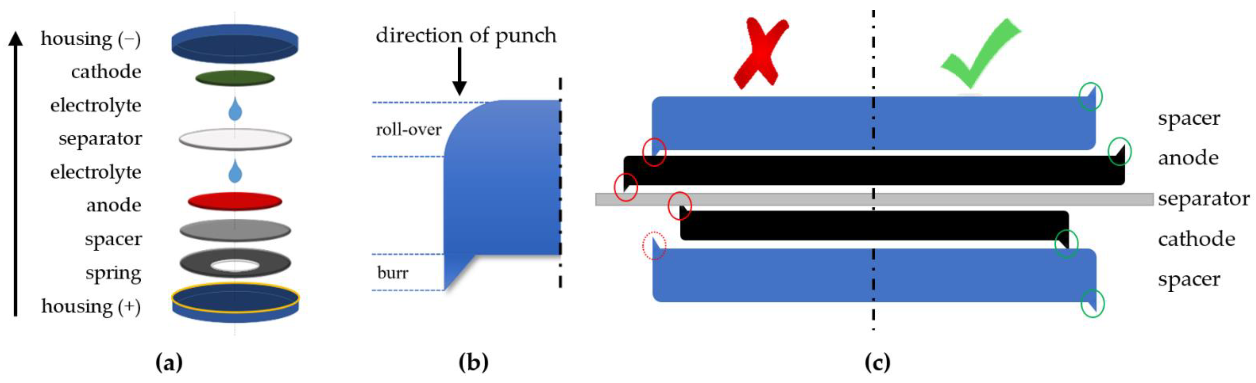
Figure 1a shows the utilized coin cell structure. According to [
17], the spacer (thickness: 1 mm) is placed with the burr facing away from the anode–separator–cathode compound (ASC) as shown in
Figure 1c (green check mark) to avoid damaging the anode. If the burrs face the separator (red cross), it is more likely that the ASC gets damaged. A total electrolyte quantity of 100 μL is used per coin cell to ensure that both the electrodes and the separator are completely wetted. During assembly, 50 µL is applied to the anode and 50 µL to the separator. Consequently, the amount of electrolyte is approximately 10% of the housing volume. A Freudenberg FS3002 with a diameter of 16.5 mm was used as the separator. The cathode is pressed lightly with the tweezers after placement to ensure the cathode does not float on the electrolyte and remains concentric to the anode during crimping.
Table 1 shows the assembly sequence used and suggested.
2.3. Swagelok Cell
The test cell comparison uses two different sizes of Swagelok cells as shown in
Figure 2. With the smaller version, the diameter of the ASC can be as little as 10 mm in diameter. With the larger housing, it can be up to 12 mm. The middle parts of the housing (8) are made of metal and must be insulated against short circuits on the inside. A plastic film (7) made of biaxially oriented polyethylene terephthalate and a thickness of approx. 0.1 mm is used, as the housing has an inside diameter of 10.3 mm or 12.2 mm. If possible, the insulating foil should cover the entire interior of the housing up to the clamping rings on each side. To insert the film into the housing, it must be brought into a cylindrical shape. In order to avoid a short circuit via the housing, the foil should be slightly larger than the inner circumference of the housing. The housings of both Swagelok cell sizes are identical in length. For the rectangular cut foils, the ideal dimensions of 25 mm (length) × 35 mm (circumference) for the small cell and 25 mm (length) × 41 mm (circumference) for the large cell have been found. Spacers (CuZn 37.6) with a diameter of 10 mm or 12 mm and a thickness of 1 mm are used to apply a homogenous pressure on the ASC. The spring (5) used for both Swagelok cell sizes is a helical compression spring (outer diameter: 9.9 mm; length: 20 mm; wire gauge: 0.9 mm; number of coils: 7). To exert pressure on the cell stack, an electrically conductive stamp (2) is inserted into the housing from both sides. The stamps have a diameter of 10 mm or 12 mm for the two case sizes. In order to be able to measure the Swagelok cells, the stamps have a thread on one side to enable contact via a screw connection. The stamps are connected to the housing with the aid of clamping rings (3 and 4) and hexagon nuts (1), and the inside of the housing is sealed off from the outside. The clamping rings come from Swagelok and are divided into front (4) and rear clamping rings (3). They are made of non-conductive nylon, polytetrafluoroethylene (PTFE) or perfluoroalkoxy alkane (PFA) to ensure insulation between the stamp and the housing and are designed for 10 mm and 12 mm tubing, respectively. The hexagon nuts are 19 mm or 22 mm (wrench size).
Table 2 shows the assembly sequence used and suggested.
2.4. EL-CELL ECC-PAT-Core
In this study, the EL-CELL ECC-PAT-Core (EL-CELL) is used in the standard ECC-Std version, which allows testing of a two-electrode configuration without a reference electrode. The components of the cell are shown in
Figure 3. The EL-CELL consists of a cell base (used as a positive pole, 3), a lid (used as a negative pole, 10), a non-conductive insulation sleeve consisting of two parts (5 and 7) into which the ASC is inserted, a lower (aluminum, 6) and an upper plunger (copper, 8), which act as spacers and transfer the compressive force evenly to the ASC, a polyethylene sealing ring (4) between the cell base and the lid, which also serves as insulation to prevent a short circuit, a stamp with a gold-plated compression spring (9), which is placed in the lid, and the bracket (1), which presses the cell base and lid together via a screw connection and at the same time exerts pressure on the ASC via the stamp on the spring.
The contact for the reference electrode (2) is tightly screwed into the cell base but is not connected to any reference electrode. The separator is clamped between the two components of the insulation sleeve and is therefore significantly larger in diameter than the electrodes inserted into the assembled sleeve. Testing different separator sizes has shown that a diameter of 21 mm is ideal so that the separator is not too big, making it uneven and not too small, making it not appropriately clamped and slipping out easily. The optimal maximum diameter of the electrodes was found to be 17.5 mm and thus does not correspond to the manufacturer’s specification of 18 mm. At 18 mm, the electrodes were a bit uneven.
Table 3 shows the assembly sequence used and suggested.
2.5. Wetting, Formation and Cyclic Aging
The assembled test cells were placed in a temperature chamber at 30 °C. Connected to the battery tester, each cell format started with a resting phase of 12 h to ensure the electrolyte reached all pores. Since this paper focuses on comparing reproducibility instead of achieving the best possible performance, the formation was performed with only one CCCV (CC: constant current; CV: constant voltage) charging cycle. For the CC phase, a current of C/10 to 4.2 V was chosen, and for the CV phase, a stop current of C/50 was chosen. After a 10 s resting phase, the cyclic aging began. With a current of C/2, the cells were charged and discharged for 30 cycles between 2.5 and 4.2 V, as shown in
Figure 4.
3. Results
For each cell format, a 22 full factorial experiment was performed. The factors separator type (Freudenberg FS3002 (+); Celgard H2013 (−)) and cathode–anode ratio (N/P ratio; N/P ratio = 1 (+); N/P ratio > 1 (−)) were examined.
Since hollow punch diameters are usually only available in 0.5 or 1 mm increments, it was impossible to achieve a fixed N/P ratio for all cell formats. According to [
16], an N/P ratio of 1.15 is recommended. It was also stated that larger ratios lead to lithium losses over a large number of cycles. However, this can be neglected here since only the first five cycles were considered.
Because the production of all test cells is a manual process that requires fine motoric skills and an understanding of the processes, all tests were performed by one assembler who produced at least 50 cells in preliminary tests.
The quality features examined are the discharge capacity, the internal resistance and the coulombic efficiency (CE). Both the discharge capacity and the internal resistance were determined for the fifth cycle since the discharge capacities of all cells from the experiments only stabilized after the fifth cycle due to the chosen formation. The CE best illustrates reactions with water or other foreign particles from the production process in the first few cycles of a lithium-ion battery [
18,
19]. For this reason, the CE, the ratio of the amount of charge removed to the amount of charge introduced, is particularly suitable for assessing the quality of the electrode coating, cell structure and electrolyte filling and distribution. Since the charge loss is most pronounced in the first cycle of the experiment and then quickly approaches 100%, this performance parameter was only recorded in the first cycle.
The empirical coefficient of variation
was used as a measure for evaluating the reproducibility. It is defined by the quotient of the empirical standard deviation (
) and the arithmetic mean of the measurements
(
) according to Formula (1).
Table 4 shows an example of the 2
2-factor plan for the small Swagelok format with all three performance parameters.
Figure 5 shows the corresponding boxplots of all three performance parameters on the left (
Figure 5a–c) and the coefficients of variation required for the comparison on the right (
Figure 5d–f). In addition, only two instead of four boxplots are shown for the coin cell and the EL-CELL. Since the cathode and the anode in the EL-CELL fit perfectly and cannot slip, it was decided to change the separator as the only factor. Only one cell from the coin cells made formation for each measurement series with the Celgard separator. For this reason, these two series of measurements are assessed as non-functional and are not taken into account in the further course of the evaluation.
The apparent differences in the boxplot values are due to the different electrode sizes. However, when considering the coefficients of variation, it becomes clear that none of the cell formats considered has a low coefficient of variation for all three performance parameters. Instead, for each of the performance parameters considered, there is a cell format that performs better than the others.
3.1. Influence of Factor Combinations on the Discharge Capacity
Figure 5d shows that the coin cell with the Freudenberg separator and an N/P ratio of one has the highest reproducibility. The next best is the small Swagelok cell with the Celgard separator and an N/P ratio greater than one.
3.2. Influence of Factor Combinations on the Internal Resistance
Figure 5e shows that the large Swagelok cell with the Celgard separator and an N/P ratio of one has the highest reproducibility. The next best is the small Swagelok cell with a Freudenberg separator with an N/P ratio greater than one.
3.3. Influence of Factor Combinations on the Coulombic Efficiency
Figure 5f shows that the large Swagelok cell with the Freudenberg separator and an N/P ratio of one has the highest reproducibility. The next best is the large Swagelok cell with the Celgard separator with an N/P ratio of one.
The average of the coefficients of variation of all evaluable measurement series for the coin cell is 14.45%. The large Swagelok cell has an average coefficient of variation of 14.57%, while the small Swagelok cell has a value of 17.69%. The mean coefficient of variation for EL-CELL is 17.23%. The coin cell has the best average value. However, since the differences are not very large, the number of cells produced is small at five per factor combination and two measurement series of the coin cell were assessed as non-functional, it is not meaningful to claim which design generally has the greatest reproducibility.
A separate consideration of the factors in the form of main effect and interaction diagrams is more informative at this point.
To determine the effects of changing factor settings on systems, plots of the main effects, as shown in
Figure 6a–c, can be derived from the corresponding coefficients of variation. When interpreting main effects plots, the steeper a line for a factor, the more influence that factor has on the system.
3.4. Influence of Individual Factors on the Internal Resistance
Figure 6b shows that the Freudenberg separator has higher internal resistance reproducibility in all cells except the EL-CELL. The separator type has the least impact on the large Swagelok cell. Looking at the N/P ratio, it turns out that the coin cell and the large Swagelok cell are more reproducible when the cathode diameter is equal to the anode diameter (N/P ratio = 1). In contrast, the small Swagelok cell gives better results with a smaller cathode diameter. The small Swagelok cell is also the least affected by the N/P ratio.
3.5. Influence of Individual Factors on the Discharge Capacity
The separator from Freudenberg has better values for the reproducibility of the discharge capacity (
Figure 6a). The large Swagelok cell is the only test cell where the Celgard separator performs better. For the EL-CELL, the slope of the diagram is almost zero, which is why the choice of separator seems irrelevant here. If the N/P ratio of one is chosen, the reproducibility of the discharge capacity of the coin and large Swagelok cells is higher. The small Swagelok cell shows the least influence on the cathode size; here, an N/P ratio greater than one is advantageous.
3.6. Influence of Individual Factors on the Coulombic Efficiency
In all cases, the coulombic efficiency shows higher reproducibility when the Freudenberg separator is used (
Figure 6c). Changing the separator when using the large Swagelok cell has the least influence on the reproducibility of the coulombic efficiency. Regarding the N/P ratio, all cases achieve better values with a cathode of the same size as the anode. Here, the coin cell is at least affected by the N/P ratio. However, it should be noted that all cells except the coin cell are cleaned and reused, while the coin cell housing, the spacer and the spring are always new. Since the degree of pollution is thus lower, the coin cell is favored when comparing the coulombic efficiency. It should also be noted that EL-CELL generally recommends changing the stamps for each cell structure.
Summarizing all the findings of the main effect diagrams, it is found that the separator from Freudenberg caused a higher reproducibility in 83% of the cases than the separator from Celgard. A similar picture emerges when choosing the cathode diameter. In 78% of the cases, an N/P ratio of one turns out to be beneficial.
3.7. Interaction between Factors
The selected experimental design also allows the interactions of the factors examined to be considered. They provide information about how much the reproducibility of the respective quality feature can change due to the factors’ interaction and are presented in
Figure 6d–f. The greater the slope of the diagrams, the more the interactions of the factors play a role in the reproducibility of the quality feature. The EL-CELL is not included in the graphs shown because it was only examined for one factor; thus, there is no interaction between the factors.
Figure 6d–f clearly shows that the interaction of the two factors examined has the least influence on the reproducibility of the three quality characteristics when using the large Swagelok cell.
4. Conclusions
This work dealt with the comparison of small-format lithium-ion batteries in terms of the reproducibility of their performance parameters. Since preliminary tests showed that both a tri-layer (PP/PE/PP; Celgard H2013) and a composite separator (PE/ceramic; Freudenberg FS3002) produced sufficiently functional cells in all designs, the separator type was chosen as a first factor in the presented main tests. In addition to the separator material, the anode–cathode ratio (1 and ~ 1.15–1.3) was given as a second factor. The quality characteristics that were examined for their reproducibility were the discharge capacity, the internal resistance and the coulombic efficiency. A total of four 22 full factor plans were performed with five cells per factor combination. The reproducibility was quantified by the coefficient of variation. Due to the small differences, no general statement can be made as to which design has the highest reproducibility when considering the mean value of the coefficients of variation of all evaluable measurement series. Depending on the series of measurements, it turned out that the highest reproducibility of the internal resistance was achieved with the large Swagelok cell, the factor combination of the Celgard separator and the same size cathode as the anode. Regarding the discharge capacity, the coin cell with a Freudenberg separator and a cathode of the same size as the anode showed the best reproducibility. For the coulombic efficiency, the best result was the large Swagelok cell with the Freudenberg separator and using the same size for the cathode and anode. However, based on the main effect diagrams, it can be seen that in ten out of twelve cases (83%), the separator from Freudenberg showed better reproducibility values than the separator from Celgard. With regard to the cathode diameter, better results could be achieved in seven out of nine cases (78%) with the same diameter as the anode. It is noted that the factors considered are not critical to optimizing reproducibility. Instead, it could be shown that all three test cell formats considered are suitable for laboratory tests. It is assumed that parameters that have not yet been examined, such as the assembler’s dexterity or fine motor skills, represent one of the greatest influencing factors on the reproducibility of test cells. For this reason, the assembler should not be changed in a series of measurements, or the assembly instructions should be as detailed as possible.
Author Contributions
Conceptualization, P.-M.L.; methodology, P.-M.L. and F.B.; software, P.-M.L. and F.B.; validation, F.B.; formal analysis, F.B. and P.-M.L.; investigation, F.B. and P.-M.L.; resources, P.-M.L. and F.B.; data curation, F.B.; writing—original draft preparation, P.-M.L. and F.B.; writing—review and editing, J.K.; visualization, P.-M.L. and F.B.; supervision, P.-M.L. and J.K.; project administration, J.K.; funding acquisition, P.-M.L. and J.K. All authors have read and agreed to the published version of the manuscript.
Funding
This research was funded by Deutsche Forschungsgemeinschaft (DFG), grant number KO4626/9-1. We acknowledge support by the German Research Foundation and the Open Access Publication Fund of TU Berlin.
Data Availability Statement
Not applicable.
Acknowledgments
The authors would like to thank Julian Long for incorporating all the measuring devices used here.
Conflicts of Interest
The authors declare no conflict of interest. The funders had no role in the design of the study; in the collection, analyses, or interpretation of data; in the writing of the manuscript; or in the decision to publish the results.
References
- Radhika, M.G.; Byatarayappa, G.; Ingale, D.V.; Bhatta, L.K.G.; Venkatesh, K.; K, S.K.M.; Nagaraju, K. High performance of asymmetric coin cells designed using optimized weight percentage of multiwalled carbon nanotubes in Ni/Co-MOFs nanocomposites. Mater. Res. Bull. 2022, 156, 111996. [Google Scholar] [CrossRef]
- Talaie, E.; Bonnick, P.; Sun, X.; Pang, Q.; Liang, X.; Nazar, L.F. Methods and Protocols for Electrochemical Energy Storage Materials Research. Chem. Mater. 2017, 29, 90–105. [Google Scholar] [CrossRef]
- Wang, P.; Zhang, X.; Yang, L.; Zhang, X.; Yang, M.; Chen, H.; Fang, D. Real-time monitoring of internal temperature evolution of the lithium-ion coin cell battery during the charge and discharge process. Extrem. Mech. Lett. 2016, 9, 459–466. [Google Scholar] [CrossRef]
- Muñoz-Rojas, D.; Leriche, J.-B.; Delacourt, C.; Poizot, P.; Palacín, M.R.; Tarascon, J.-M. Development and implementation of a high temperature electrochemical cell for lithium batteries. Electrochem. Commun. 2007, 9, 708–712. [Google Scholar] [CrossRef]
- Rowden, B.; Garcia-Araez, N. Estimating lithium-ion battery behavior from half-cell data. Energy Rep. 2021, 7, 97–103. [Google Scholar] [CrossRef]
- Vortmann-Westhoven, B.; Winter, M.; Nowak, S. Where is the lithium? Quantitative determination of the lithium distribution in lithium ion battery cells: Investigations on the influence of the temperature, the C-rate and the cell type. J. Power Sources 2017, 346, 63–70. [Google Scholar] [CrossRef]
- Bach, T.C.; Schuster, S.F.; Fleder, E.; Müller, J.; Brand, M.J.; Lorrmann, H.; Jossen, A.; Sextl, G. Nonlinear aging of cylindrical lithium-ion cells linked to heterogeneous compression. J. Energy Storage 2016, 5, 212–223. [Google Scholar] [CrossRef]
- Gabrielli, G.; Marinaro, M.; Mancini, M.; Axmann, P.; Wohlfahrt-Mehrens, M. A new approach for compensating the irreversible capacity loss of high-energy Si/C|LiNi0.5Mn1.5O4 lithium-ion batteries. J. Power Sources 2017, 351, 35–44. [Google Scholar] [CrossRef]
- Peng, C.; Lahtinen, K.; Medina, E.; Kauranen, P.; Karppinen, M.; Kallio, T.; Wilson, B.P.; Lundström, M. Role of impurity copper in Li-ion battery recycling to LiCoO2 cathode materials. J. Power Sources 2020, 450, 227630. [Google Scholar] [CrossRef]
- Sieg, J.; Schmid, A.U.; Rau, L.; Gesterkamp, A.; Storch, M.; Spier, B.; Birke, K.P.; Sauer, D.U. Fast-charging capability of lithium-ion cells: Influence of electrode aging and electrolyte consumption. Appl. Energy 2022, 305, 117747. [Google Scholar] [CrossRef]
- Wagner, N.P.; Asheim, K.; Vullum-Bruer, F.; Svensson, A.M. Performance and failure analysis of full cell lithium ion battery with LiNi0.8Co0.15Al0.05O2 and silicon electrodes. J. Power Sources 2019, 437, 226884. [Google Scholar] [CrossRef]
- Schmid, A.U.; Kurka, M.; Birke, K.P. Reproducibility of Li-ion cell reassembling processes and their influence on coin cell aging. J. Energy Storage 2019, 24, 100732. [Google Scholar] [CrossRef]
- Murray, V.; Hall, D.S.; Dahn, J.R. A Guide to Full Coin Cell Making for Academic Researchers. J. Electrochem. Soc. 2019, 166, A329–A333. [Google Scholar] [CrossRef]
- Long, B.R.; Rinaldo, S.G.; Gallagher, K.G.; Dees, D.W.; Trask, S.E.; Polzin, B.J.; Jansen, A.N.; Abraham, D.P.; Bloom, I.; Bareño, J.; et al. Enabling High-Energy, High-Voltage Lithium-Ion Cells: Standardization of Coin-Cell Assembly, Electrochemical Testing, and Evaluation of Full Cells. J. Electrochem. Soc. 2016, 163, A2999–A3009. [Google Scholar] [CrossRef]
- Kayyar, A.; Huang, J.; Samiee, M.; Luo, J. Construction and testing of coin cells of lithium ion batteries. J. Vis. Exp. 2012, e4104. [Google Scholar] [CrossRef] [PubMed] [Green Version]
- Hu, J.; Wu, B.; Chae, S.; Lochala, J.; Bi, Y.; Xiao, J. Achieving highly reproducible results in graphite-based Li-ion full coin cells. Joule 2021, 5, 1011–1015. [Google Scholar] [CrossRef]
- Luc, P.-M.; Bauer, S.; Kowal, J. Reproducible Production of Lithium-Ion Coin Cells. Energies, 2022; in peer review. [Google Scholar]
- Korthauer, R. Handbuch Lithium-Ionen-Batterien; Springer: Berlin/Heidelberg, Germany, 2013; ISBN 978-3-642-30652-5. [Google Scholar]
- Li, W.; Lucht, B.L. Inhibition of the Detrimental Effects of Water Impurities in Lithium-Ion Batteries. Electrochem. Solid-State Lett. 2007, 10, A115. [Google Scholar] [CrossRef]
| Publisher’s Note: MDPI stays neutral with regard to jurisdictional claims in published maps and institutional affiliations. |
© 2022 by the authors. Licensee MDPI, Basel, Switzerland. This article is an open access article distributed under the terms and conditions of the Creative Commons Attribution (CC BY) license (https://creativecommons.org/licenses/by/4.0/).


