1. Introduction
The battery management system is the power battery control unit, which is an important part of the power battery to ensure the stability of battery performance. The research on the battery management system promotes the improvement of battery performance and affects the development of power battery. Balance control is the core technology of the battery management system, which directly impacts the power performance and battery life of the vehicle. Battery inconsistency will lead to the “barrel effect“; the battery pack will be due to the problem of battery reaching the cut-off conditions early, reducing the performance of the battery. The battery equalization control function can improve the inconsistency of the battery, so that the battery can generate an energy transfer between the inconsistent batteries during the working process, avoid the above adverse results, and improve the energy utilization rate of the battery pack [
1,
2].
The equalization method can be divided into two kinds. The first is dissipative equalization. By adding the energy dissipation components in the circuit, the battery cell with higher power consumes energy through energy dissipation components to achieve an equalization effect. The second is non-dissipative equalization, which uses components that can temporarily store and release energy to achieve equalization through energy transfer. The active equalization method can transfer the energy of inconsistent batteries without additional energy consumption. The core devices in this equalization circuit are mainly capacitors, inductors, transformers, etc. [
3].
At present, the main research direction for an equilibrium control system is non-dissipative equilibrium. Many scholars have conducted research in this direction and provided scientific research results for reference. Ji Xiang proposed a modular battery balancing scheme for multiple transformers with double secondary windings, with secondary windings in each module connected to each other. Each module can be balanced individually by a transformer at the same time, or the energy can be balanced across modules by connecting the secondary windings to each other. This scheme can balance multiple batteries at the same time and improve the equalization speed of the battery [
4]. Yang Daiming uses multiple bidirectional flyback DC converters to establish an equalization topology, which can realize the energy transfer from a single battery to a battery pack and the energy transfer from a battery pack to a battery cell. The average equalization current is determined according to the resistance value connected to the MOSFET, and the equalization control experiment is carried out by using an equalization control chip, which controls multiple batteries. The voltage difference can be reduced from 24.1 mV to 13.3 mV, and it is proven that the voltage cannot have a good equalization effect due to polarization [
5]. Li Jun adopts the equalization topology based on a flyback DC–DC converter, combined with PID control and fuzzy control theory, and proposes a “peak clipping and valley filling” battery equalization system based on fuzzy PID control. The simulation analysis of six batteries in a charge and discharge state is carried out. Compared with the equalization method without fuzzy control, the equalization speed can be increased by more than 40% [
6]. Guo Xiangwei uses an equalization topology based on a flyback DC–DC converter, so that the equalization energy can be transmitted between the battery pack and any battery. Using a dual-objective hybrid control strategy, by balancing the highest voltage battery and the lowest voltage battery, the number of equalization batteries is reduced, and the equalization speed of the battery is improved. The effectiveness of the equalization scheme is proven by simulation and experiment [
7]. Zhao Chuanting proposed a balanced topology structure based on a reconfigurable converter, used an inductor as the balanced element, and designed four working modes, so that the battery could transfer the energy between modules. The simulation results proved that this scheme could effectively improve the balanced speed [
8]. Arzu Turksoy compares a variety of equalization circuits based on inductors and DC converters. By analyzing and comparing the equalization time, equalization efficiency, and cost of each scheme, it is found that most equalization schemes based on flyback DC converters use SOC as an equalization variable. Compared with the DC–DC equalization scheme, the equalization efficiency is higher, and the time used is shorter [
9]. Li Yu adopts the unitized equalization method of the multi-winding transformer and uses the principle of forward converter and flyback converter at the same time. When the battery pack transfers the energy to some battery units, the principle of the forward converter is used for equalization. When some battery units are equalized to the battery, the principle of the flyback converter is used. This scheme reduces the number of components and can balance multiple battery cells at the same time to obtain higher time efficiency. Through the analysis of the experimental results, the equalization efficiency can reach 84.8% [
10].
Through a study of the research status of equalization control, it is found that the equalization strategy based on the equalization topology of the bidirectional flyback DC–DC converter is generally the “peak clipping and valley filling” type equalization. In this equalization process, the low-power battery needs to be discharged as part of the battery pack. At the same time, it is also charged as the balanced object, resulting in additional energy consumption; at the same time, this method can only achieve the balance between the single battery and the battery pack and cannot make the equalization process occur between any batteries. Based on the bidirectional flyback DC–DC converter, this paper proposes an active equalization topology, which can realize the movement of energy between any batteries and make the equalization process only occur between batteries with inconsistent power. With SOC as the equilibrium variable, the FFRLS-EKF algorithm is used to improve the accuracy of SOC estimation. The model of the equalization control system is established in the software, and simulation analysis is carried out.
The first chapter of this paper analyzes the research status of the battery equalization control system, finds out the shortcomings of the “peak clipping and valley filling” equalization strategy used in other kinds of literature, and explains the research direction and research purpose of this paper. In the second chapter, the working principle of the “peak clipping and valley filling” equilibrium strategy is introduced in detail, and the shortcomings of this method are analyzed. The third chapter classifies the inconsistent states of the battery and describes the working principle of the equalization control system of each inconsistent state in detail. In the fourth chapter, the process of selecting SOC as the equilibrium variable and the process of determining the equilibrium threshold are analyzed, and the strategy of the equilibrium control system is determined by combining the SOC estimation algorithm. In the fifth chapter, the simulation model of the equalization control system is built, and the model structure is described. The sixth chapter simulates and analyzes the “peak clipping and valley filling” equalization strategy and the equalization method used in this paper and compares the results to illustrate the advantages of the equalization control system used in this paper from multiple perspectives.
2. Equilibrium Principle Based on “Peak Clipping and Valley Filling” Equilibrium Strategy
In the research based on flyback DC converter, many equalization systems use the “peak clipping and valley filling” equalization strategy. Under this strategy, the battery will have different equilibrium processes under different working conditions. In the charging process, the battery with higher power transfers the energy to the battery pack through the flyback DC converter to ensure that the battery pack will not stop charging because of the high power of a single battery. This process is called “peak clipping”; during the discharge process, the battery pack transfers the energy to the low-power battery through a flyback DC converter to ensure that the battery pack does not terminate the discharge in advance because of the low power of a single battery. This process is called “valley filling“. In the static state, the battery will determine the inconsistent state of the battery and select the “peak clipping” or “valley filling” equalization method. This paper uses the topology of six batteries for analysis.
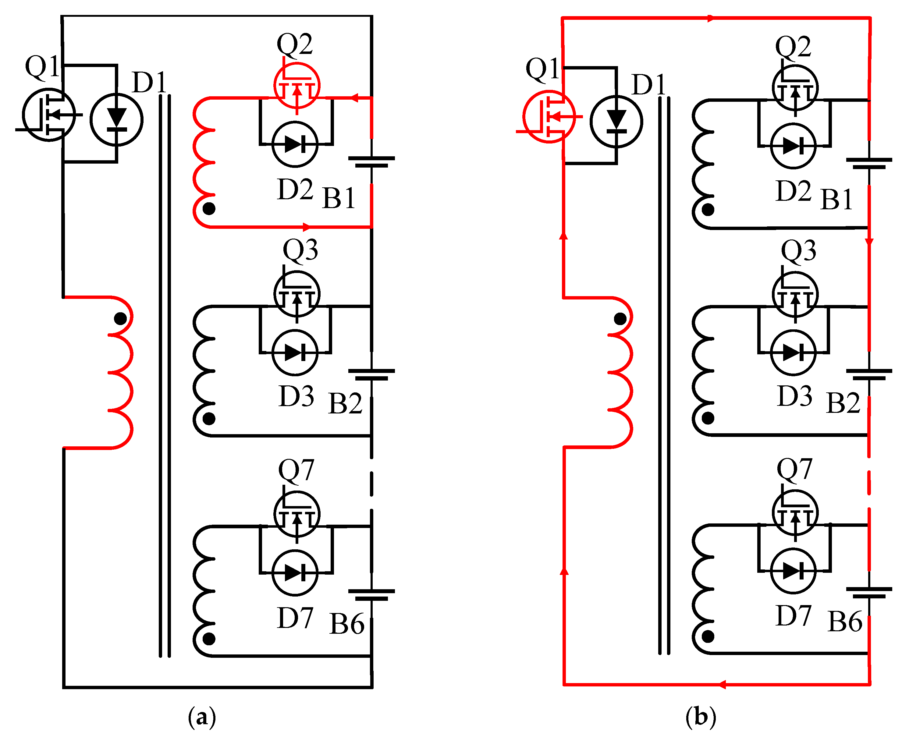
The equalization process in the “peak cutting” state is shown in
Figure 1. The battery B1 has high power, and the battery transfers the energy to the secondary winding of the converter through the MOSFET Q2. The converter’s electromagnetic induction causes the battery’s primary winding to generate voltage after the MOSFET Q1 is turned on. The primary winding transmits the energy to the battery pack, reducing the power of the target battery and keeping the battery pack’s energy balanced. The equalization process in the “valley filling” state is shown in
Figure 2. The battery B6 has low power, and the battery pack transfers the energy to the primary winding through the MOSFET Q1. The converter’s electromagnetic induction causes the battery’s secondary winding to generate the current, and the conduction MOSFET Q7 transmits the energy to the low-power battery cell, thereby increasing the power of the target battery and maintaining the energy balance of the battery pack [
11].
By studying the equilibrium process of “peak load shifting”, it can be found that in the “peak load shifting” state, the high-capacity battery first discharges to the battery pack and is then charged as part of the battery pack; in the “valley filling” state, the low-power battery is discharged as part of the battery pack and is then charged as a balancing target. It can be found from the above that the balanced battery not only acts as an equalization party but also becomes an equalization party, which increases the energy loss and reduces the equalization effect. Therefore, given the above problems, this paper improves the equalization control system based on a flyback DC converter, so that the energy transfer only occurs in the battery that needs to be balanced and reduces the loss during energy transfer.
3. Topology and Working Principle of Equalization Control System
3.1. Topological Structure of Equilibrium Control System
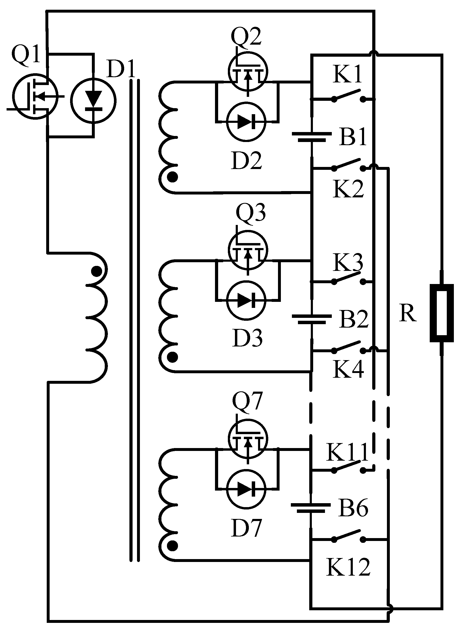
This chapter uses a balanced topology based on a coaxial multi-winding bidirectional flyback DC converter, and the structure is shown in
Figure 3. In the figure, B1–B6 are the power batteries; Q1–Q7 are the MOSFETs, which are responsible for the conduction of the corresponding battery and the secondary winding; D1–D7 are the diodes, accountable for cutting off the current of the corresponding circuit; K1–K12 is a controllable switch, which is responsible for the energy transfer from the primary winding to each battery. Each battery is connected with a MOSFET, a secondary winding, and a controllable switch. Through the MOSFET and the secondary winding, the energy of the battery can be transferred to the secondary winding. Through the controllable switch, the energy can be transferred from the primary side winding to the battery. This structure allows energy transfer only between the batteries that need to be balanced.
K1–K12 are controllable switches controlled by the control part of the equalization system. After the control part obtains the position of the battery SOC maximum value, the corresponding MOSFET is controlled to turn on, so that the battery with the largest power discharges to the secondary winding. The secondary winding generates the current, and the energy is transmitted to the primary winding through electromagnetic induction. When the MOSFET of the secondary winding is disconnected, the diode of the primary winding is turned on, and the primary winding generates the current. At this time, the control part obtains the position of the SOC minimum value and controls the corresponding controllable switch, so that the current of the primary side winding flows into the low-power battery. When an energy transfer cycle ends, the controllable switch is disconnected. The controllable switch is controlled by the control part of the equalization system. By detecting the position of the minimum value of the battery SOC, the control command is sent to the controllable switch corresponding to the battery. When the extreme value of the battery pack meets the consistency requirement, the equalization control system no longer sends commands to the controllable switch, and the switch remains disconnected.
3.2. Working Principle of Equilibrium Control System
Because there is a variety of battery inconsistencies, and different inconsistency states, the battery has different working principles.
The inconsistency types of batteries are classified according to the number of batteries that need to be balanced. The inconsistency types of batteries can be divided into three categories:
Because the battery with inconsistent power may be a single-cell or multi-cell battery at any position in the battery pack, other batteries with normal power cannot form a reconstructed battery pack to supply the power to this inconsistent battery, so in response to the inconsistency of multi-cell batteries, two single high- and low-power battery equalization groups are randomly matched, and multiple equalization groups work alternately to complete the equalization of multi-cell batteries. The following is the working principle for each type of inconsistency.
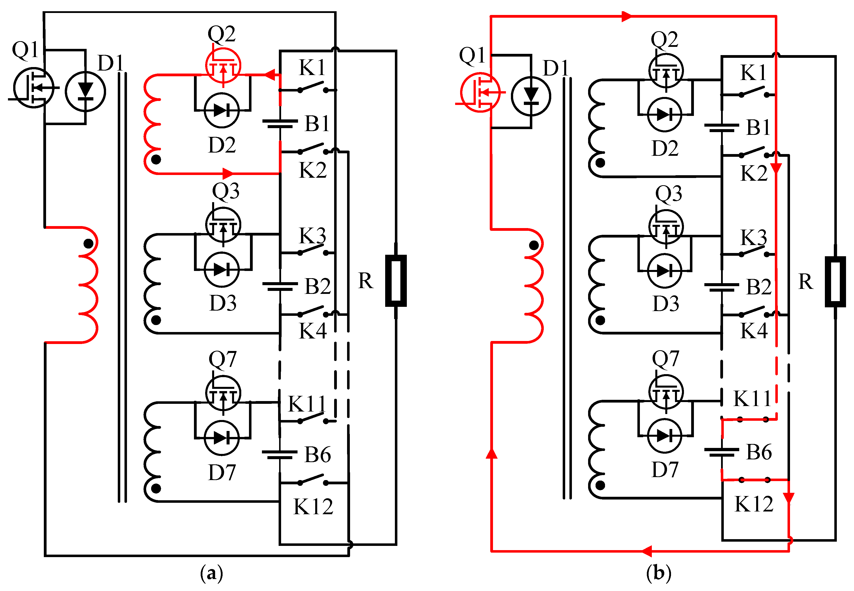
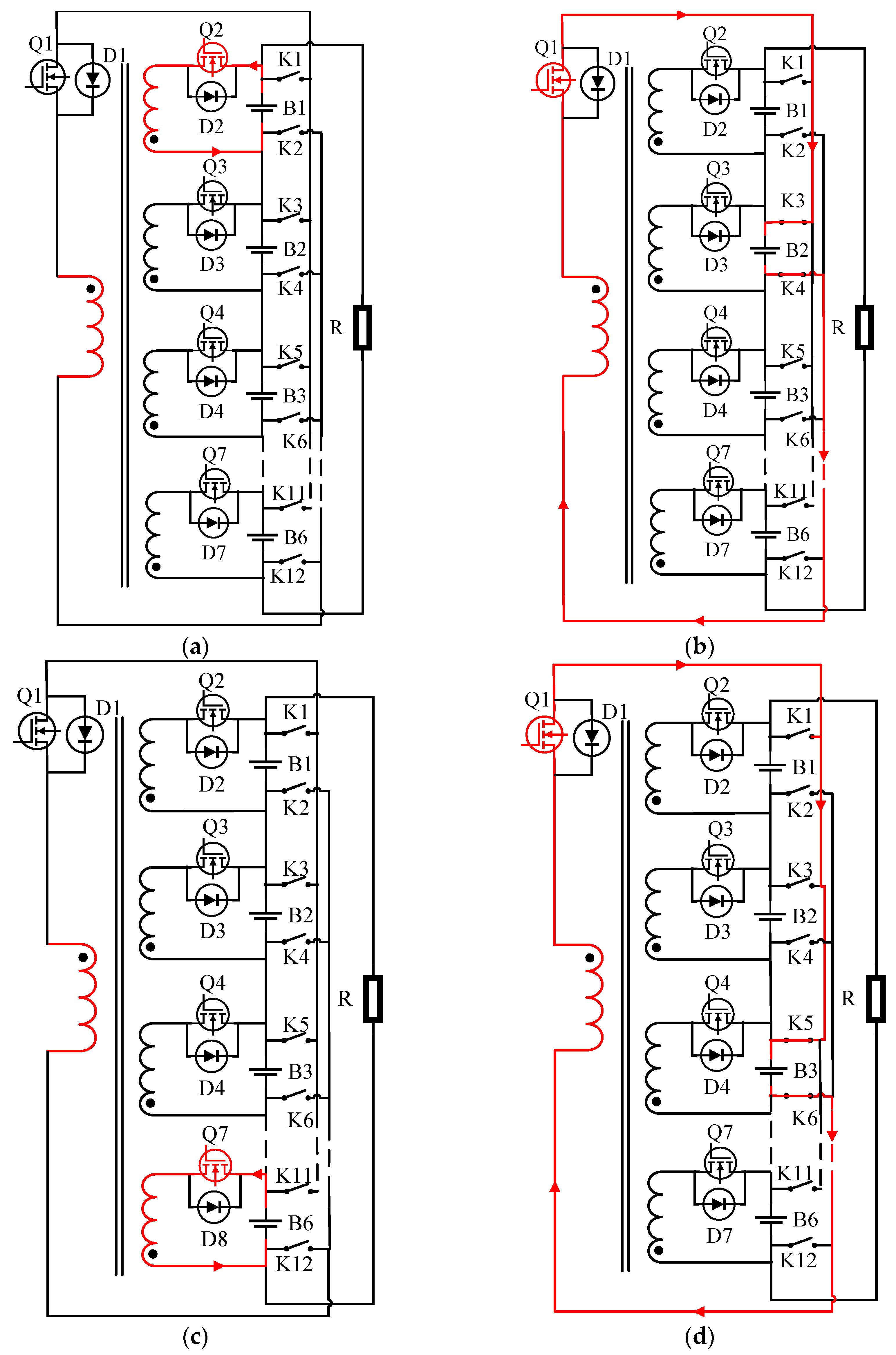
1. Balanced mode 1: this mode is for a single cell to a single cell energy transfer. Assuming that the power of battery B1 is high, and the power of battery B3 is low, the equalization system detects that the power difference between the batteries satisfies the inconsistency condition, and the equalization system is turned on. This process is the energy transfer between battery B1 and battery B6. Firstly, the MOSFET Q2 is turned on, and the secondary side winding produces the working current. Part of the electric energy of battery B1 is stored in the secondary side winding, and the primary side winding generates voltage due to electromagnetic induction. The working process is shown in
Figure 4a. Then, the MOSFET Q2 is turned off, and the controllable switches K11 and K12 are connected with the MOSFET Q7 of the primary winding, and the energy of the primary winding is transferred to battery B6. The working process is shown in
Figure 4b. The equalization process is completed when the power difference between B6 and B1 is reduced to meet the requirements.
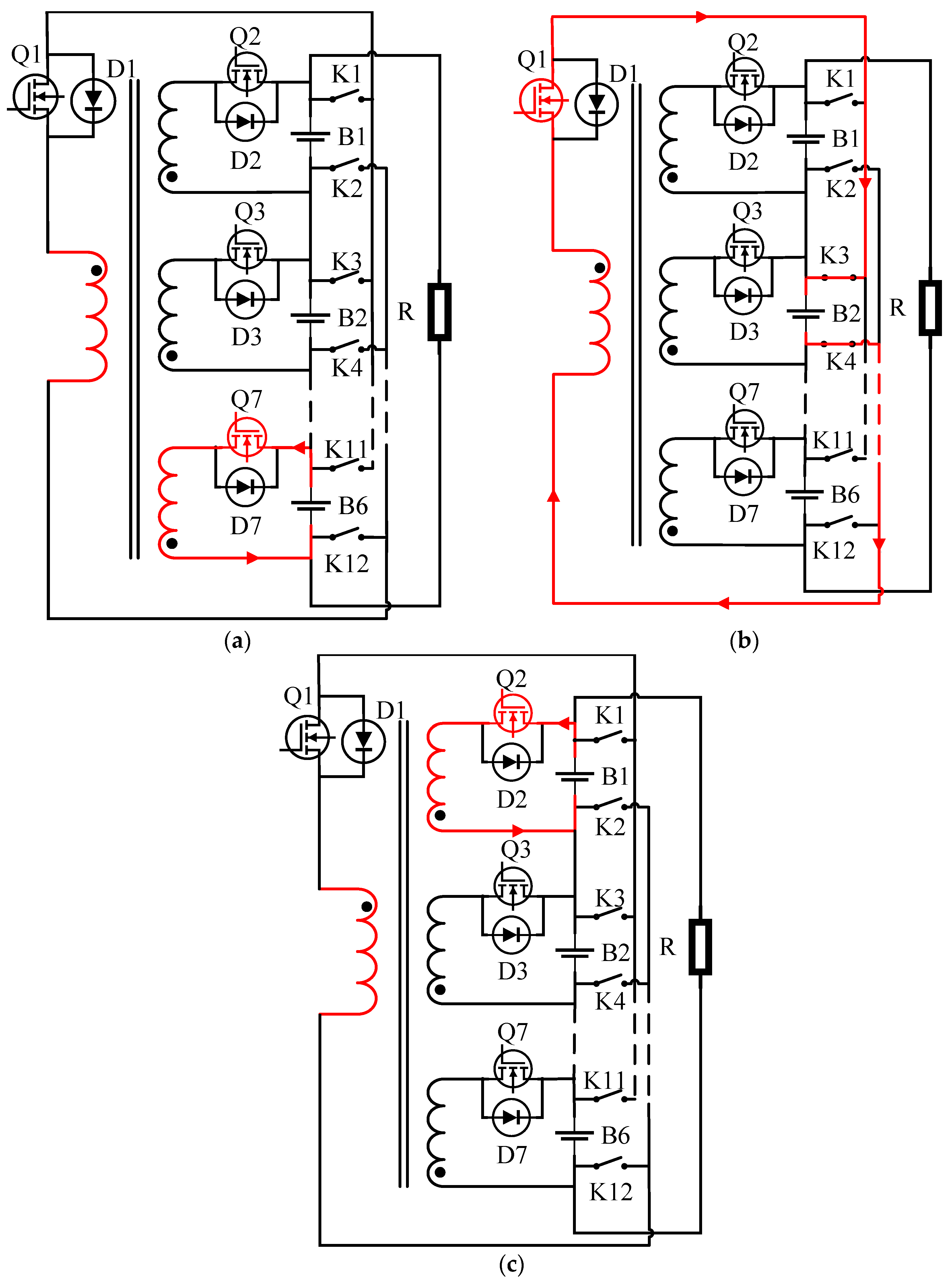
2. Equilibrium mode 2: energy transfer from multi-cell high-capacity batteries to low-capacity battery cells. Battery B2 has the lowest battery power, and batteries B1 and B6 have relatively high and equal power. When the power range of the battery pack meets the equalization opening condition, the equalization function is turned on, and the energy is transferred from battery B1 and B6 to battery B2. Since the inconsistent battery is in the middle position, the equalization group needs to be randomly matched during the equalization process. First, battery B6 and battery B2 form an equalization group, and the energy is transferred from battery B6 to battery B2. The MOSFET Q7 is turned on, and battery B6 transfers the energy to the secondary winding. After the secondary winding generates the current, the primary winding generates the voltage due to electromagnetic induction, and the working process is shown in
Figure 5a; the MOSFET Q7 is turned off, Q1, K3, and K4 are turned on, and the power of the primary winding is transferred to battery B2, as shown in
Figure 5b. At the next moment, batteries B1 and B2 form an equalization group to transfer the energy between the two cells. First, battery B1 transfers the energy to the secondary winding, and the secondary winding generates the voltage to the primary winding through electromagnetic induction. The primary winding transfers the energy to battery B2 through Q1, K3, and K4. The working process is shown in
Figure 3b,c. Batteries B1 and B3, in turn, form an equalization group with battery B2 for energy transfer until the battery power range meets the inconsistency requirement, and the equalization function is turned off.
3. Equilibrium mode 3: this mode is suitable for energy transfer from multi-cell high-power batteries to multi-cell low-power batteries. It is assumed that the power of batteries B1 and B6 is high and the same, and the power of batteries B2 and B3 is low and the same. Firstly, two batteries are randomly selected from the high-capacity battery pack and the low-capacity battery pack to form an equalization group. Firstly, battery B1 and battery B2 form an equalization group. The equalization method is similar to the energy transfer method of the single battery to the single battery in equalization mode 1. The equalization process is Q2 turn-on, the battery B1 discharges to the secondary side winding, and the voltage is generated in the primary side winding due to electromagnetic induction. Disconnected, Q1, K3, and K4 are turned on, and the primary winding transfers the energy to battery B2. The equalization process is shown in
Figure 6a,b. At the next moment, the equalization group composed of B3 and B6 performs the energy transfer. The equalization process is Q7 conduction, and battery B6 performs the energy transfer to the secondary winding. Because the electromagnetic induction primary winding generates the voltage, Q7 is turned off, Q1, K5, and K6 are turned on, and the energy on the primary winding is transferred to battery B3. The energy transfer equalization process is shown in
Figure 6c,d. When the batteries satisfy the consistency condition, the equalization system is closed.
For each battery inconsistency, the equalization system uses a corresponding equalization mode, and the above three equalization modes are also applicable to the battery charging state, discharging state, and shelving state.
4. Equilibrium Strategy Design of Equilibrium Control System
The above three equilibrium modes apply to the battery charging, discharging, and shelf state. For each battery inconsistency, the equilibrium system will use different equilibrium modes.
4.1. Selection of Equilibrium Variables in Equilibrium Control System
The inconsistency of the battery mainly refers to the inconsistency of the remaining capacity of the battery, so the variables of the equalization control system are the parameters reflecting the battery’s remaining capacity. The terminal voltage and SOC of the battery can reflect the residual state of the battery [
13]. Now, the two battery parameters are analyzed:
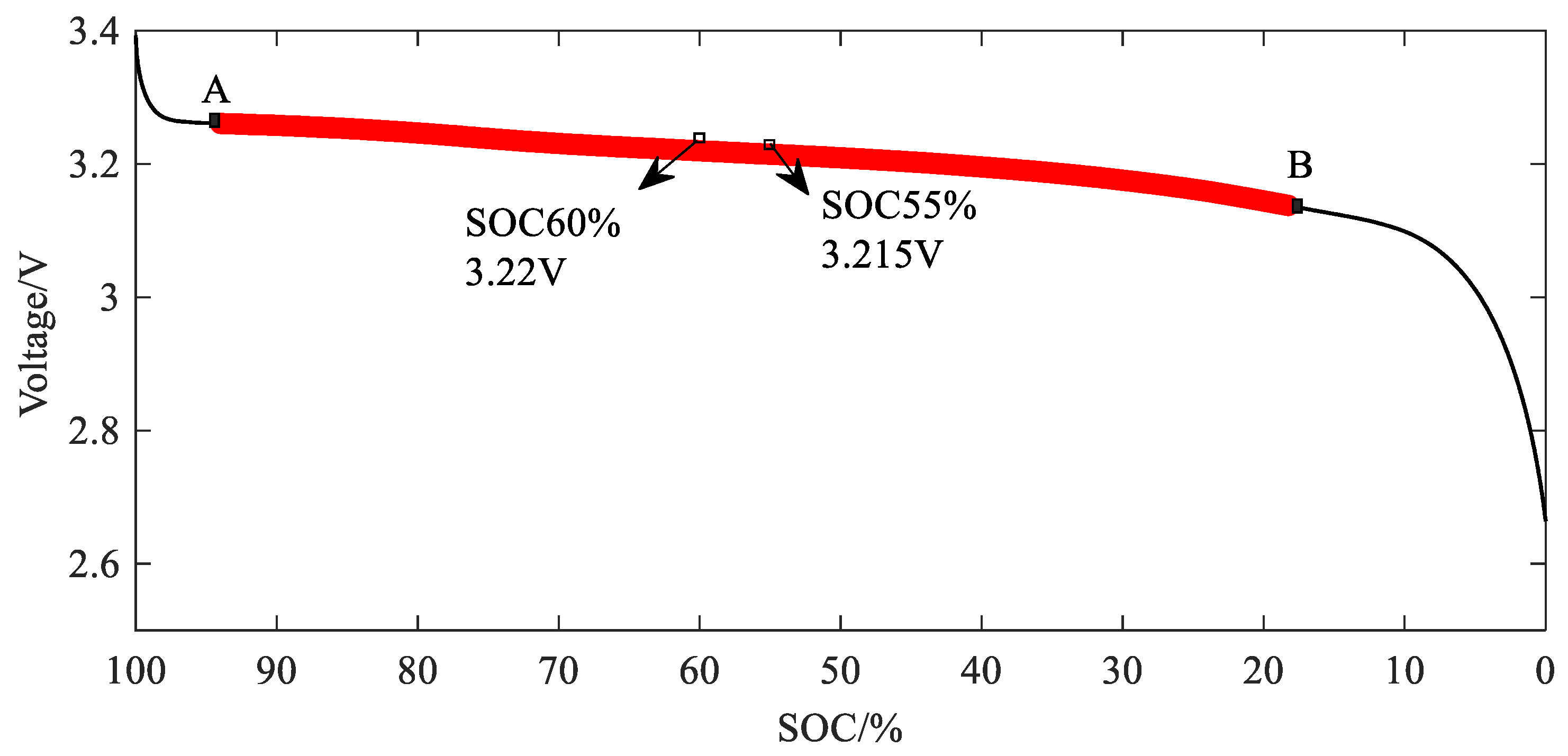
1. As shown in
Figure 7, the battery voltage plateau exists in the A-B period. The terminal voltage change is relatively gentle. Even if the SOC changes greatly, the terminal voltage change is still relatively small. When the SOC is 60% and 55%, the equilibrium opening condition is satisfied, but the terminal voltage in this state is 3.22 V and 3.215 V, respectively, and the voltage difference is only 5 mV, which does not meet the equilibrium opening condition. Therefore, if the terminal voltage is used as the equilibrium variable at this stage, the equilibrium effect will be reduced.
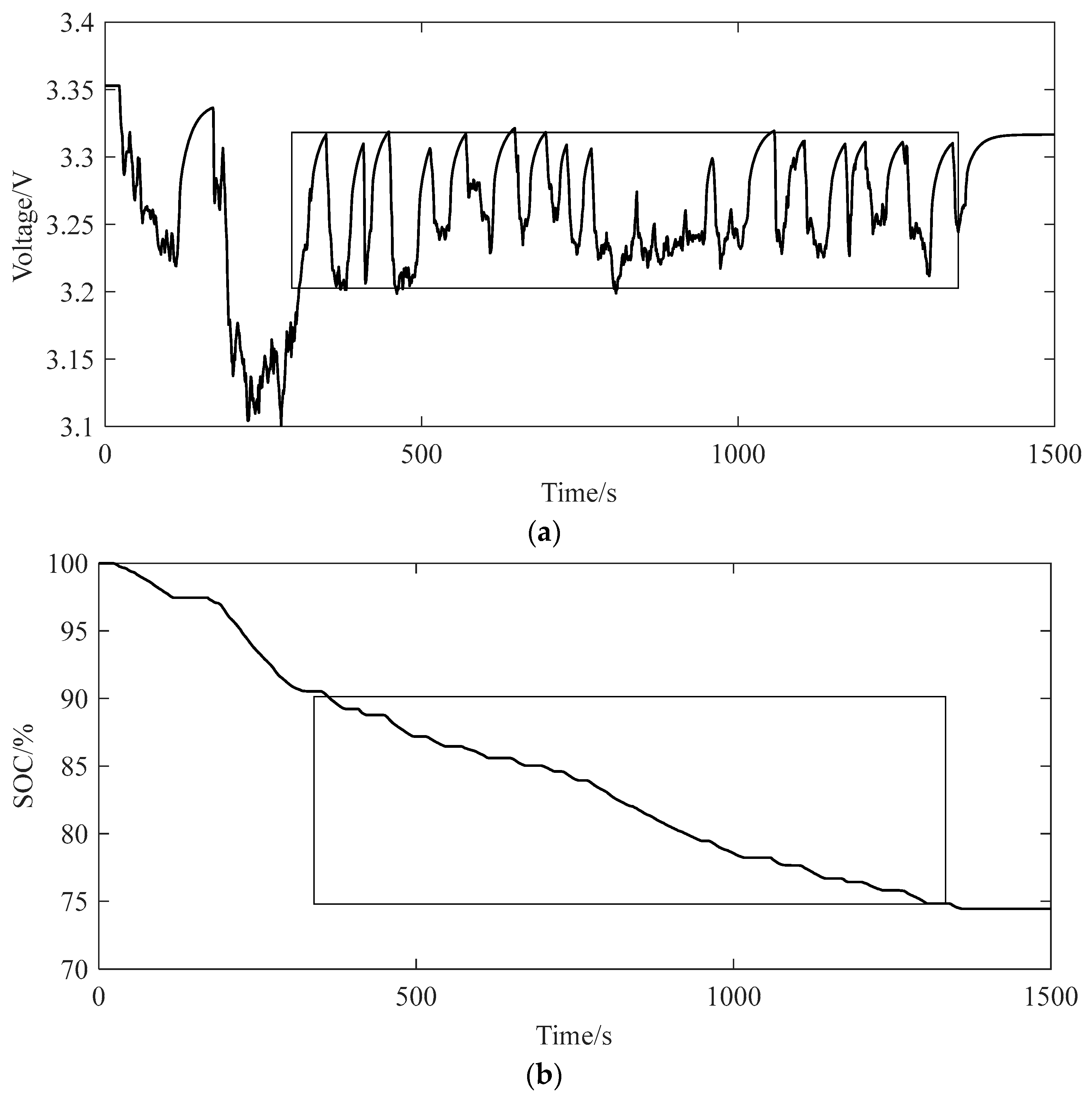
2. The voltage also frequently changes under the condition of frequent current changes, which makes the voltage range of the battery pack unstable and also affects the accuracy of the equalization control system in judging the state of the battery pack. The change of SOC is gentle under the condition of frequent change in the current, which can ensure the stability of the SOC range [
14]. The voltage variation under the UDDS condition is shown in
Figure 8a. The part in the frame fluctuates greatly, and the voltage variance is 0.0021. The change of SOC under the same working condition is shown in
Figure 8b. The part change in the frame is relatively gentle, and the variance of SOC is 0.0012. It can be seen from the curves and data in the figure that SOC can maintain a stable trend under complex conditions.
3. Using the appropriate estimation algorithm for SOC estimation can obtain a higher-precision SOC value. Taking SOC as the equalization variable, the SOC estimation algorithm, and equalization control system combined can improve the equalization control effect.
In summary, SOC can more accurately reflect the remaining capacity of the battery during the voltage platform period of the battery, can maintain a certain stability when the current fluctuates greatly, and can obtain more accurate results through the SOC estimation method. This paper chooses SOC as the equilibrium variable.
4.2. The Setting of Judgment Threshold of Balance Control System
The equilibrium threshold is the condition of equilibrium opening and closing. The equilibrium threshold with SOC as the equilibrium variable can be composed of the extreme value, average value, and variance of SOC. When the battery works, the equilibrium threshold is determined by the state of each parameter.
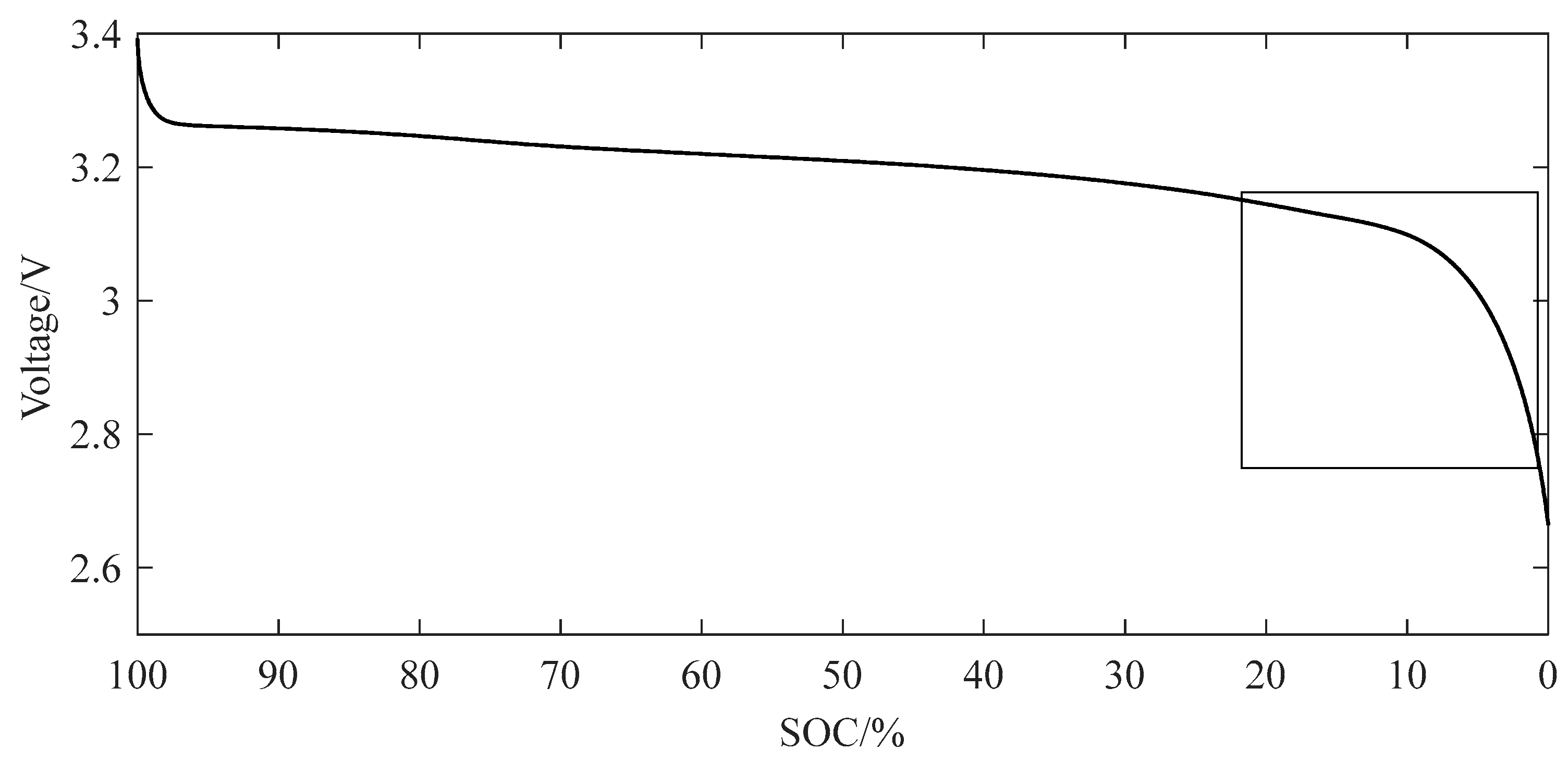
1. The battery in different SOC state terminal voltage is not the same, as shown in
Figure 9. When the battery is in a non-voltage platform, the voltage changes faster. In the range of 0–20% SOC, 10 points are selected to observe the voltage change. It can be seen from the data in
Table 1 that when SOC ≥ 10%, the voltage change of the adjacent two points is less than 13 mV, and when SOC ≤ 10%, the voltage change of the adjacent two points is above 26 mV. For example, the SOC of A battery is 10%, and the SOC of B battery is 8%. At this time, the voltage difference between the two batteries is 23 mV. To reduce the voltage difference, an energy balance between the two batteries is needed. Considering the acquisition accuracy, the SOC range threshold is 1%. That is, when the battery SOC range is greater than 1%, the battery meets the inconsistency conditions.
2. It is shown in
Section 3.2 that the battery has different working principles under other consistency states. The relationship between SOC extremum (SOCmax, SOCmin) and SOC mean is set to determine the conditions for using different equalization working principles.
This paper uses six batteries for equalization simulation, which is calculated in the case of six batteries. The above analysis determines the SOC range threshold, according to this threshold, to determine the degree of dispersion of SOC. Assuming that the SOC value of battery B1 is SOC1, let the SOC value of the other batteries be the critical state when the battery is balanced. That is, let the other batteries be the value when the SOC range of the battery pack is 1%, and the SOC value of batteries B2-B6 can be SOC1 + 1% or SOC1 − 1%. According to the value of the equilibrium opening critical condition, the average value of the battery satisfying this critical strip is obtained, namely the inequality
By solving this inequality, we can obtain
The results show that when the difference between the battery SOC extreme value and the SOC average value is less than 0.8%, the battery SOC extreme value threshold is satisfied. Considering the equalization effect, the threshold between the battery SOC range and the SOC mean is set to 0.5%. When the battery turns on the equalization function, it is judged whether the difference between the SOC maximum value, the minimum value, and the SOC mean value is greater than 0.5%, and the inconsistency state of the battery is determined according to the judgment result [
15].
4.3. SOC Estimation Method
After determining the use of SOC as an equilibrium variable, the SOC estimation method of the battery is discussed. Based on the current understanding of the current research status of SOC and the inspiration brought by the literature of this research direction, the battery SOC is estimated using a model-based estimation method. Firstly, the FFRLS method is used to identify the model parameters, and then, the EKF method is used to estimate the battery SOC.
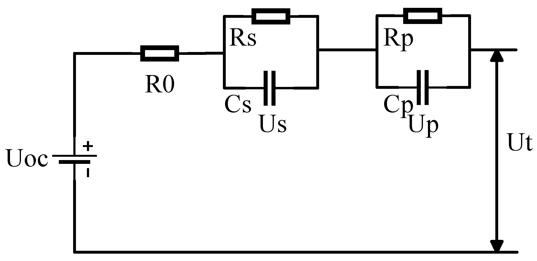
The Thevenin model of the second-order RC network is selected as the battery equivalent circuit model, as shown in
Figure 10.
The system state equation of the model is obtained according to Kirchhoff’s law:
U
oc is the open circuit voltage, U
t is terminal voltage, I is the working current, R
p, R
s is the polarization resistance, C
p, C
s is the polarization capacitance, R
0 is the ohmic resistance, U
p, U
s is the polarization voltage. The ohmic internal resistance, polarization resistance, and polarization capacitance need to be identified by a certain method, and the open circuit voltage needs to be obtained by the battery SOC state [
16].
- 2.
Model online parameter identification
The internal resistance and open circuit voltage of the battery will change with the different working environments of the battery, thus affecting the parameters of the battery. In this part, the least squares with forgetting factor (FFRLS) algorithm is used to identify the parameters of the equivalent circuit model in real time to enhance the anti-interference of the battery parameters to the external environment.
The parameter matrix θ and the observation variable matrix
can be obtained by the data during the battery operation. After initialization of some parameters in the algorithm, the iterative calculation of the FFRLS method can be carried out.
In the formula,
is the forgetting factor, K
k is the algorithm gain, and Pk is the error covariance matrix. Because
, the value of the parameter matrix is only the intermediate variable in the parameter calculation process, not the battery parameter. It is necessary to continue to calculate the value in the parameter matrix. The calculation method is as follows (4), and R
0, R
p, R
s, C
p, C
s can be obtained [
17].
- 3.
SOC estimation algorithm
The battery parameters obtained in the “2. Model online parameter identification” section above are applied to the EKF algorithm to estimate the battery SOC. The required data are the current and terminal voltage when the battery is working. The following is the iterative calculation process of the EKF algorithm.
In Formula (5), is the prior state value of the state vector, is the posterior state value of the state vector, is the prior state error covariance matrix, Pk is the posterior state error covariance matrix, and ek is the innovation.
Before the calculation, some parameters in the EKF algorithm should be initialized. The parameters that need to be initialized are the system state vector a, the error covariance matrix Pk, and the system noise error covariance matrix Qk. Let the error covariance matrix P0 = σ1I, σ1 = 10−4, I is the unit vector. Let the system noise error covariance matrix P0 = σ2I, σ2 = 106. The system state vector is composed of polarization voltage Us, Up, and battery SOC at time k, and the initial value is assigned to the system state vector according to the actual situation. Through iteration, the system state vector can be obtained, which includes the SOC estimation results.
The system state vector
can be obtained through iteration, which contains the SOC estimation result [
18].
4.4. The Formulation of Equilibrium Control System Strategy
After the equilibrium variables and thresholds are determined, the equilibrium strategy is formulated. First, the SOC of each battery is calculated, the inconsistency state of the battery is judged, and the balance mode of the battery is selected according to the inconsistency state of the battery [
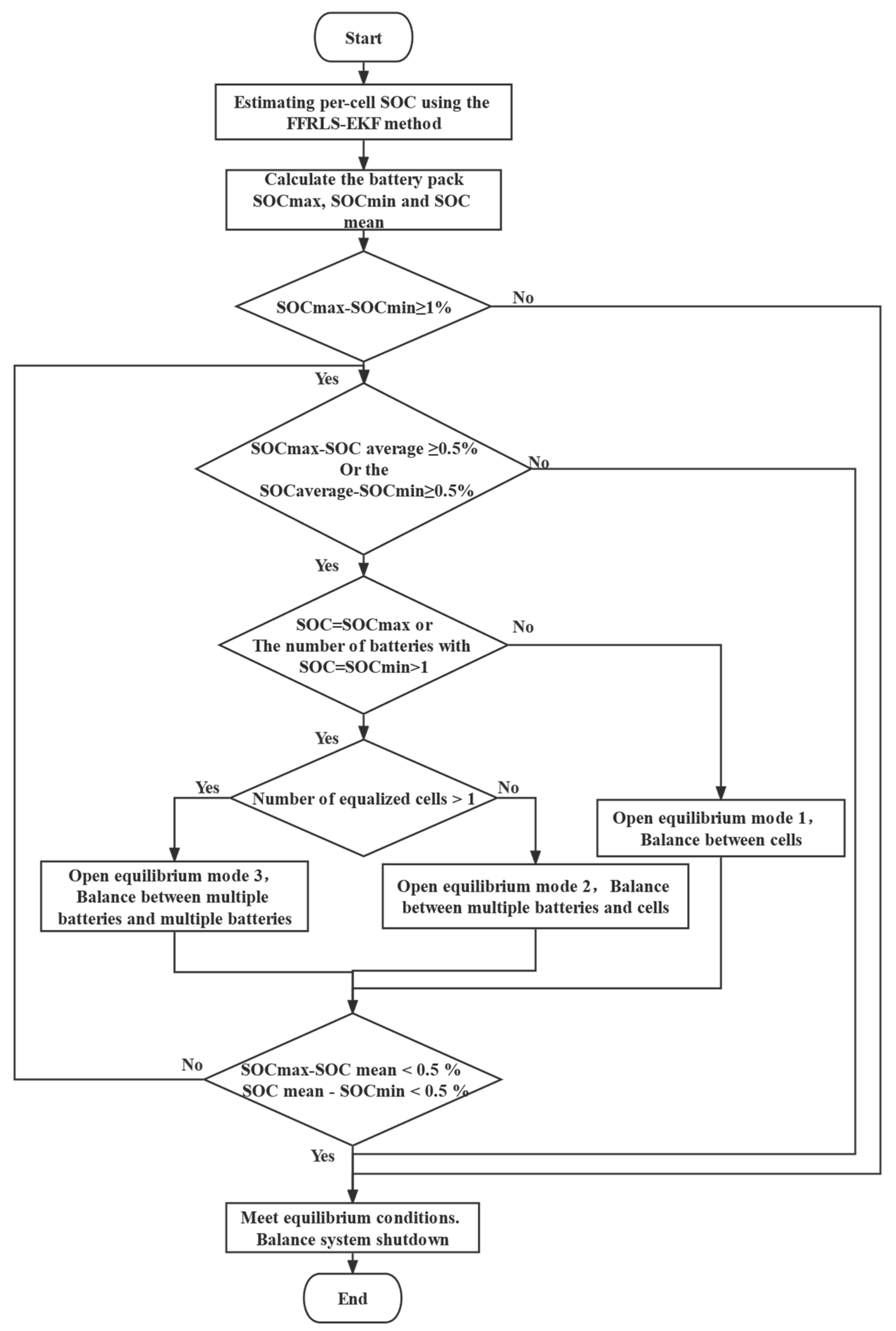
19]. The flow chart of the balancing strategy is shown in
Figure 11.
First, the SOC estimation method based on FFRLS-EKF is used to estimate the SOC of each battery, and the SOC of each battery is obtained. Then, according to the SOC value of each battery, the SOC extreme value and the SOC average value of the battery pack are calculated, and it is judged according to the balancing threshold whether the turn-on condition of the balancing system is satisfied.
When the battery SOC maximum and the difference between the SOC minimum value and the SOC average value is greater than 0.5%, and the battery with the SOC value of the maximum and the minimum value is a single cell, the equalization of the single cell to the single cell is started, and the equalization process is equalized.
When the difference between the minimum SOC value and the mean SOC value of the battery is greater than 0.5%, and the battery with the minimum SOC value is a single cell, the equalization of multiple high-power batteries to low-power battery cells is opened, which conforms to the equilibrium mode 2.
When the difference between the battery SOC maximum and the SOC average is greater than 0.5%, the difference between the battery SOC minimum and the SOC average is also greater than 0.5%, and the battery that takes the SOC maximum and the battery that takes the SOC minimum is multiple, the inconsistency of the battery conforms to the equilibrium mode 3.
5. Model Construction of Power Battery Balance Control System
According to the above equalization control system topology, equalization control strategy, and SOC estimation method, the equalization control system is built in Matlab/Simulink.
5.1. Bidirectional Flyback DC Converter Module
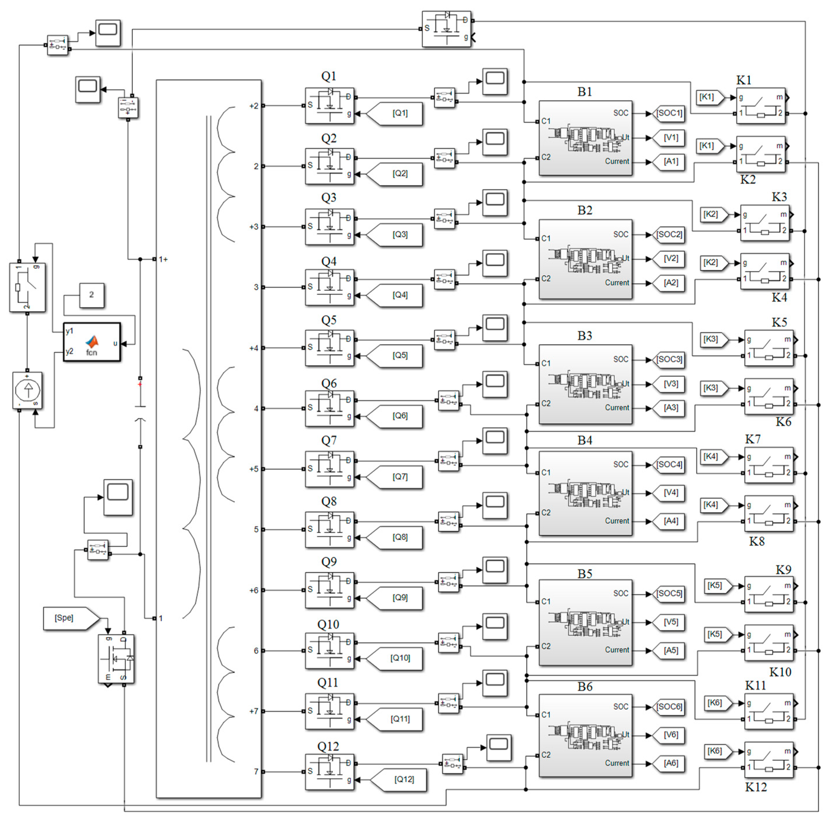
As shown in
Figure 12, this module is the execution part of the balanced topology, which is responsible for generating the working current, completing the battery energy transfer, controlling the controllable switches and switches, outputting the battery current, voltage, SOC, and other functions. The left side of the diagram is a coaxial multi-winding transformer and controllable current source, and the right side is the battery pack and control element. The battery pack consists of six battery SOC estimation modules connected in series. Each battery is connected to the secondary winding of the transformer by a MOSFET and to the primary winding of the transformer by a controllable switch [
20].
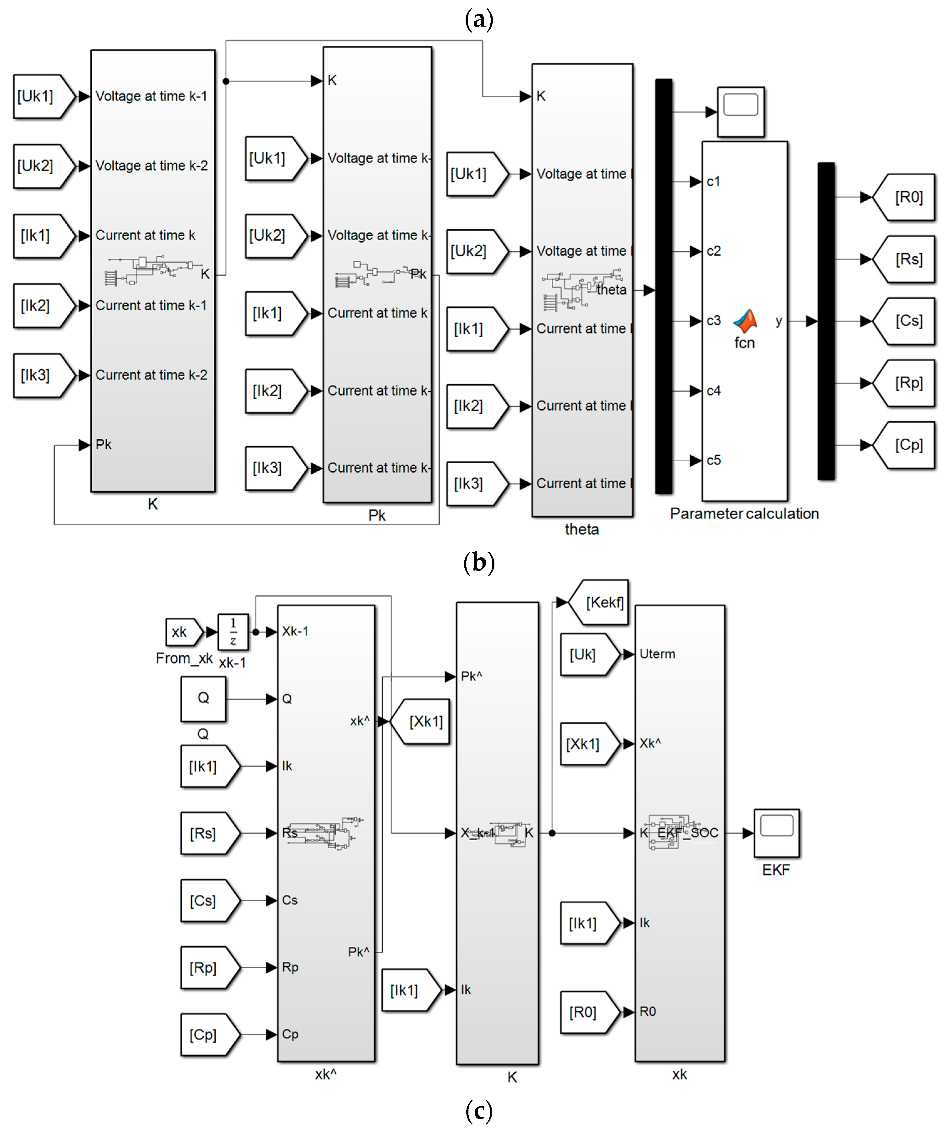
5.2. Battery SOC Estimation Module
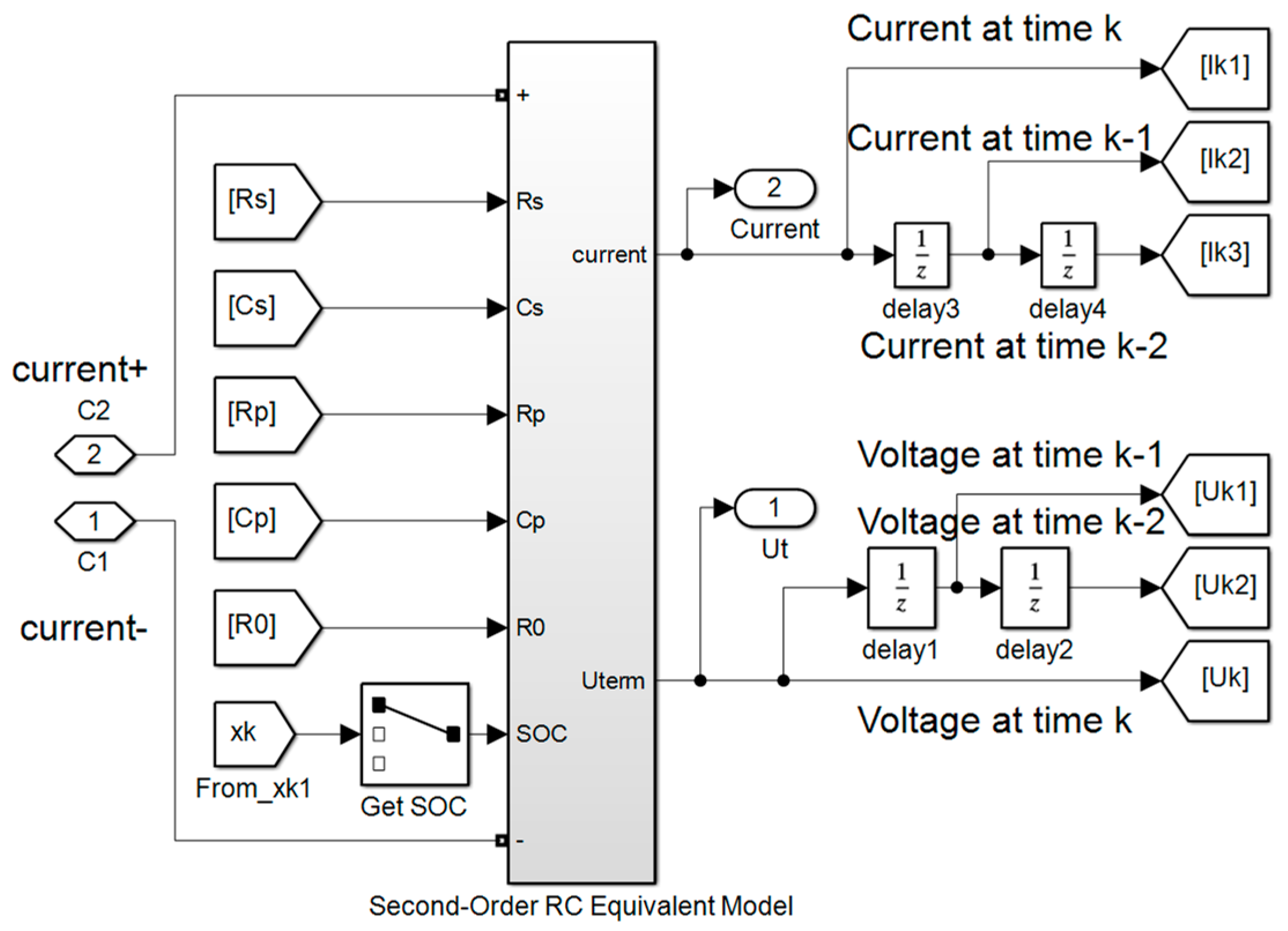
As shown in
Figure 13, this module consists of three parts, namely: the battery equivalent circuit part in (a), which receives the external current, calculates the battery terminal voltage, output current, and terminal voltage through the parameters of FFRLS and open circuit voltage [
21]; (b) this is the online parameter identification part of the FFRLS method, which receives the battery current and terminal voltage for parameter estimation and transmits the parameters to the equivalent circuit model part and the EKF estimation part [
22,
23]; (c) is the EKF estimation part, which receives the current, terminal voltage, and battery parameters. SOC estimation is then performed.
The battery parameters are set according to the data in
Table 2.
6. Simulation Verification and Result Analysis of Balanced Control System
After completing the construction of the battery equalization system model, the model is simulated under multiple operating conditions; at the same time, the equalization control system using the “peak clipping and valley filling” equalization strategy is simulated under the same working conditions. The simulation results of the two equalization systems are compared to prove the advantages of the battery equalization system used in this paper.
The initial SOC of the battery is set, and the two equalization control systems are simulated under charging, discharging, standing, New Europe Drive Cycle (NEDC) and UDDS conditions.
6.1. Equalization Simulation Verification and Result Analysis of Charging State
Set the initial battery SOC according to
Table 3, simulate the two equalization schemes, and set the charging current to 30A.
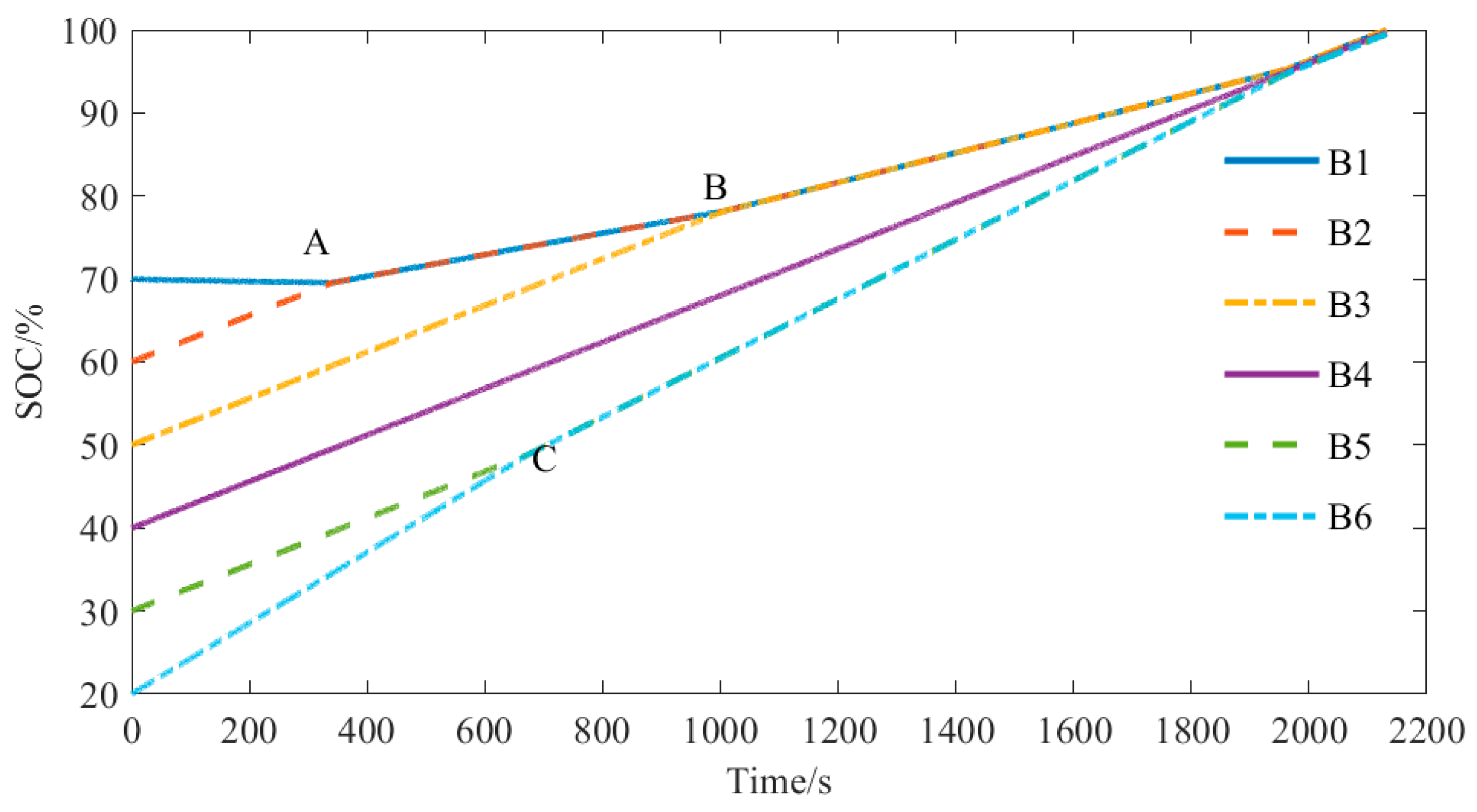
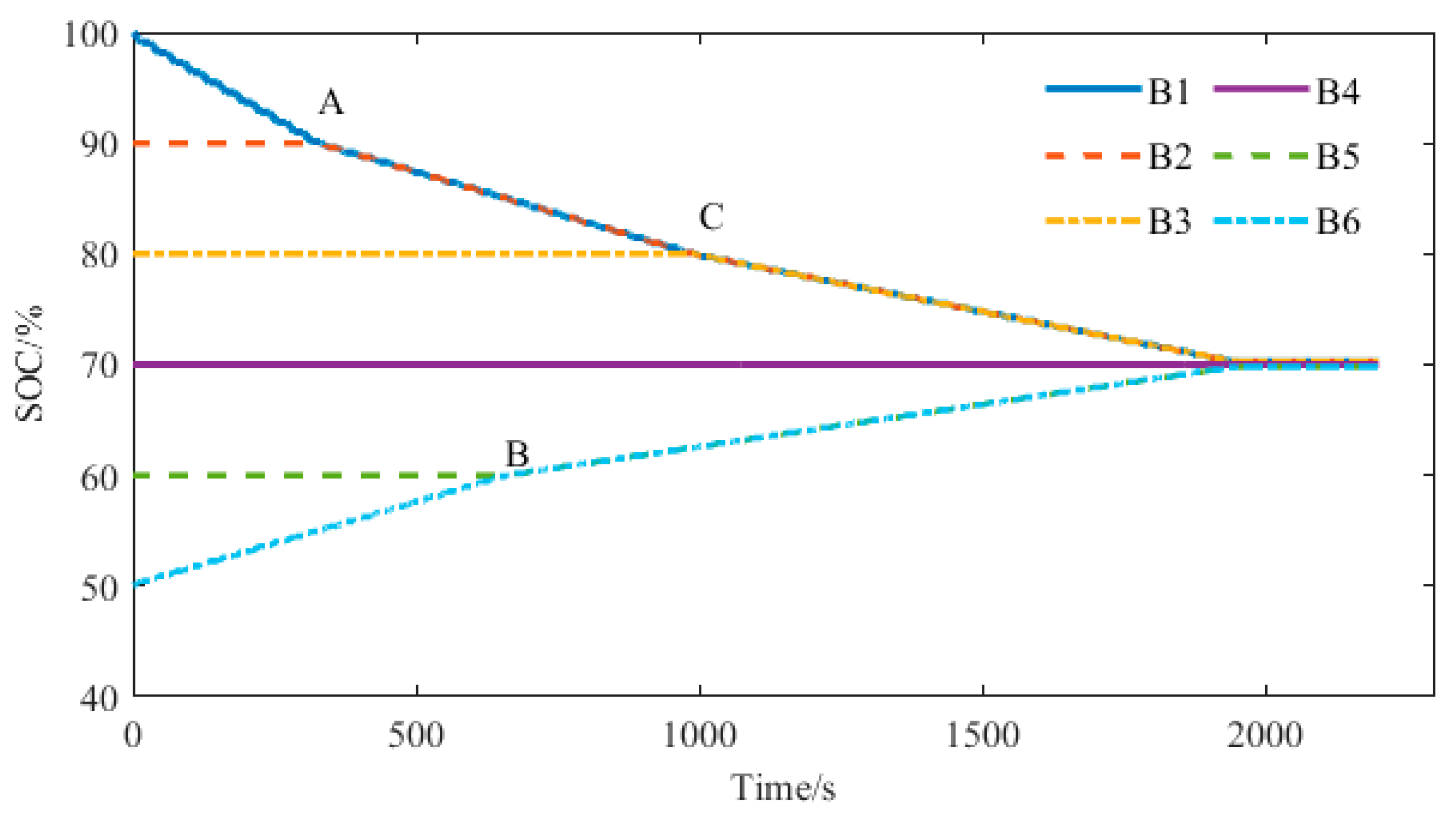
Firstly, the equalization scheme of this paper is used for equalization simulation. The equalization process is shown in
Figure 14. Battery B1 takes the maximum value of SOC, and B6 takes the minimum value of SOC. Battery B1 charges battery B6, which conforms to equalization mode 1. When battery B1 discharges to point A, battery B1 and battery B2 have the same SOC value, both of which charge to battery B6, conforming to the equilibrium mode 2; when battery B6 is charged to the C point, the SOC of battery B5 is the same as that of battery B5, and both batteries are balanced. Batteries B1 and B2 charge to B5 and B6, which conforms to the equilibrium mode 3; after the B point, batteries B1, B2, and B3 transfer the energy to B5 and B6. At the time t = 1990 s, the SOC range is less than 1%, and the equilibrium is completed.
To prove the advantages of the method used in this paper, the equilibrium system using “peak clipping” equalization strategy is simulated. The “peak clipping” equalization strategy is used in the battery charging state, which can avoid the maximum capacity battery from first reaching the charging cut-off condition and stopping charging. It can be seen from
Table 1 that battery B1 takes the maximum SOC. According to the “peak clipping” equalization strategy, the energy transfer from battery B1 to the battery pack is required. The equalization process is shown in
Figure 15. Battery B1 transfers the energy to the battery pack through the DC converter. The power of battery B1 decreases, the battery pack receives the energy of battery B1 and is charged, and the power of the other batteries in the battery pack continues to increase. At time t = 2320 s, the SOC range of the battery pack meets the requirements, and the equalization is completed.
The simulation results are analyzed to obtain balanced data, as shown in the
Table 4. In the scheme of this paper, the energy released when the equalization is completed is 27 Ah, the energy charged is 21.3 Ah, and the equalization efficiency is 79%; after peak shaving equalization, the consumed power is 60 Ah, the charged energy is 45 Ah, and the equalization efficiency is 73%. In contrast, in the charging state, compared with the “peak clipping” equalization, the proposed scheme consumes 55% less power, has 8% higher efficiency, and 18% faster equalization time [
24].
6.2. Equilibrium Simulation Verification and Result Analysis of Discharge Phase
The initial SOC of the battery is set according to
Table 1, and the two equalization schemes are simulated. The discharge current is set to 30 A.
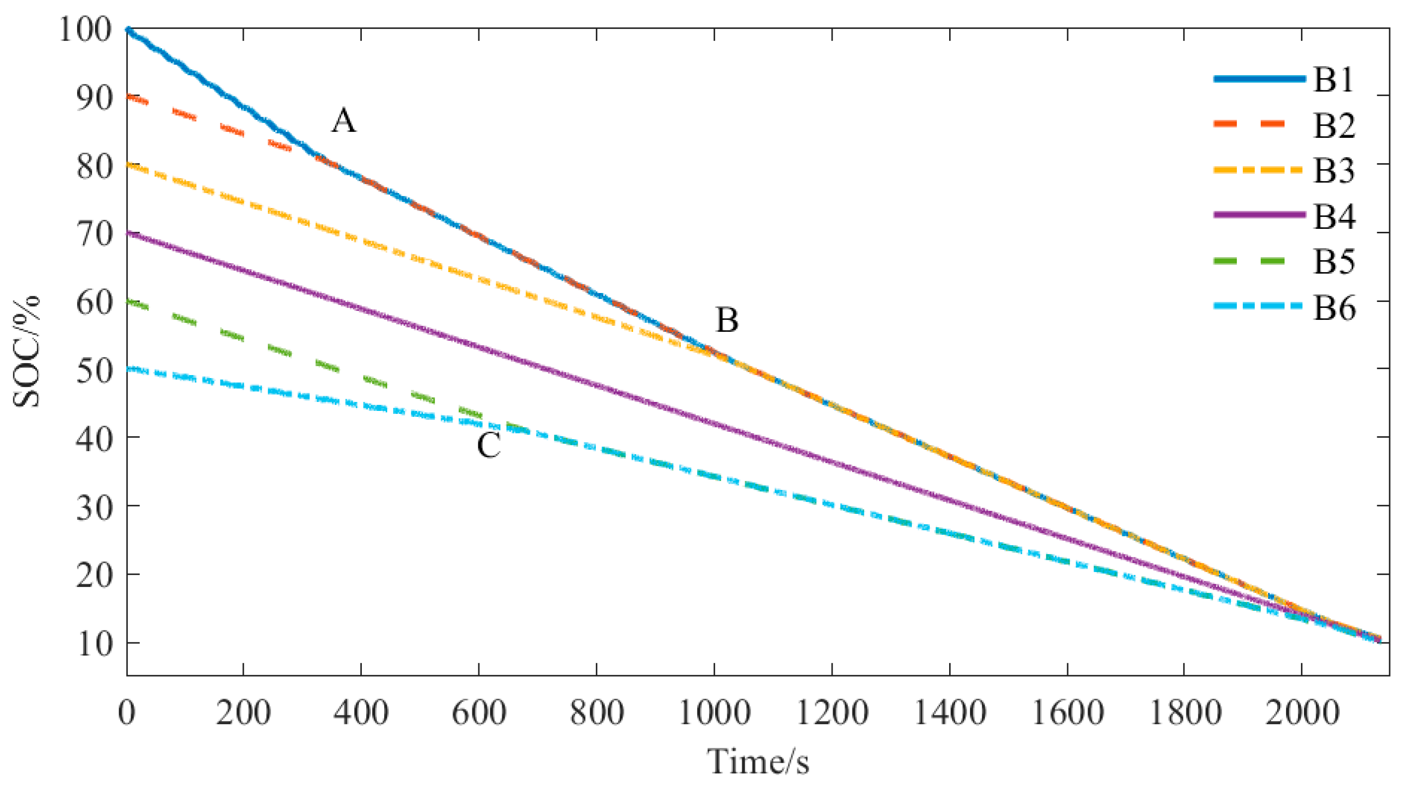
The scheme of this paper is as follows: battery B1 takes the maximum value of SOC, B6 takes the minimum value of SOC, and the maximum value of SOC is greater than 1%. Battery B1 is balanced to battery B6, which conforms to the state of equilibrium mode 1. When battery B1 discharges to point A, the SOC values of battery B1 and battery B2 are the same, and the two batteries charge to battery B6, which conforms to equilibrium mode 2. When balancing to point C, battery B5 and battery B6 become balanced objects, and batteries B1 and B2 charge to batteries B5 and B6, conforming to the balanced mode 3; at point B, batteries B1, B2, and B3 simultaneously transfer the energy to batteries B5 and B6. The battery SOC range is less than 1%; the equalization process is completed. The equalization process is shown in
Figure 16.
After completing the equilibrium simulation of the equilibrium method in this paper, in order to compare the equilibrium method of the equilibrium method and the “valley filling” equilibrium strategy, the equilibrium system of the “valley filling” equilibrium strategy is simulated. The “valley filling” equalization strategy is mainly used in the discharge state in order to avoid the lowest power battery first reaching the discharge end and causing the battery pack to stop discharging in advance. It can be seen from
Table 3 that battery B6 has the lowest power. According to the “valley filling” equalization strategy, the energy transfer from the battery pack to the low-power battery is required. After the equalization begins, the battery pack transfers the energy to battery B6 through a DC converter, and battery B6‘s power increases until it is the same as the other batteries in the battery pack. The equalization process is shown in
Figure 17. At time t = 2800 s, the range of the battery pack meets the requirements, and the equalization is completed.
The simulation results are analyzed to obtain balanced data, as shown in the following table. In the scheme of this paper, the energy released when the equalization is completed is 33.6 Ah, the energy filled is 27 Ah, and the equalization efficiency is 80%. After valley filling equalization, the consumed power is 65 Ah, the filled energy is 40 Ah, and the equalization efficiency is 61.5%. In contrast, in the charging state, the proposed scheme consumes 25% less power, has 74% higher efficiency, and 27% faster time than the valley filling balancing scheme [
25]. The results of the two equalization methods are shown in
Table 5.
6.3. Equilibrium Simulation Verification and Result Analysis in Standing Phase
The initial SOC of the battery is set according to
Table 1, and the two equalization schemes are simulated. This state is static, and the current is zero.
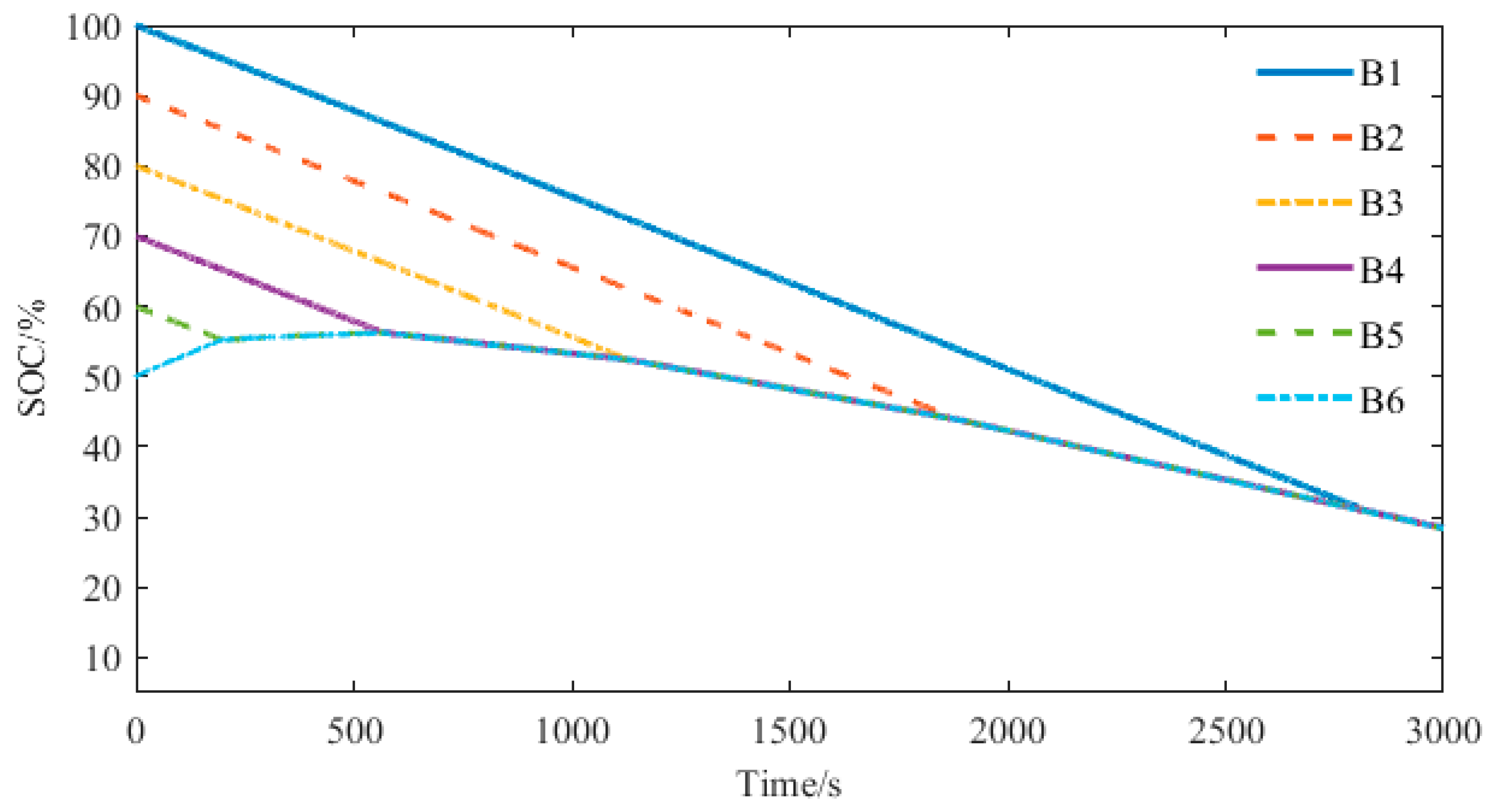
In the equalization strategy of this paper, the batteries with the maximum value and the minimum value of SOC form an equalization group to complete the equalization. In the beginning, the single battery discharges to the single battery, conforming to the equilibrium mode 1; at point A, battery B1 and battery B2 discharge to battery B6, which conforms to equilibrium mode 2; at point B, battery B1 and battery B2 discharge to battery B5 and battery B6, which conforms to equilibrium mode 3. At the t = 1800 s, the SOC range is 0.47%, complete with equalization. The equalization process in the static state is shown in
Figure 18.
According to the initial SOC state, the “peak clipping” method can be selected for balance. In the “peak clipping” equilibrium state, because the SOC of battery B1 is the maximum value, battery B1 discharges to the battery pack, the battery pack receives the energy of battery B1, and the power gradually increases. At 2620 s, the SOC range of the battery is 0.49%, and the equilibrium is completed. This equalization process is shown in
Figure 19.
Because the secondary winding of the DC converter model is 2:1, when the power of the transformer is constant, the ratio of the primary winding current to the secondary winding current is 1:2, and the current is larger, so the high-battery battery releases the energy faster, and the low-battery battery receives the energy slower. When the SOC is about 70%, the equalization process is completed.
The simulation results are analyzed to obtain balanced data, as shown in the following table. In the scheme of this paper, the energy released when the equilibrium is completed is 35.4 Ah, the energy filled is 29 Ah, and the equilibrium efficiency is 82%. After peak shaving equalization, the consumed power is 58 Ah, and the charged energy is 40 Ah, and the equalization efficiency is 69%. In contrast, in the charging state, the power consumption of this scheme is 39% lower, the efficiency is 19% higher, and the time is 32% faster [
26]. The equilibrium results of the two equilibrium methods are shown in
Table 6.
6.4. Equilibrium Simulation Verification and Result Analysis under Different Conditions
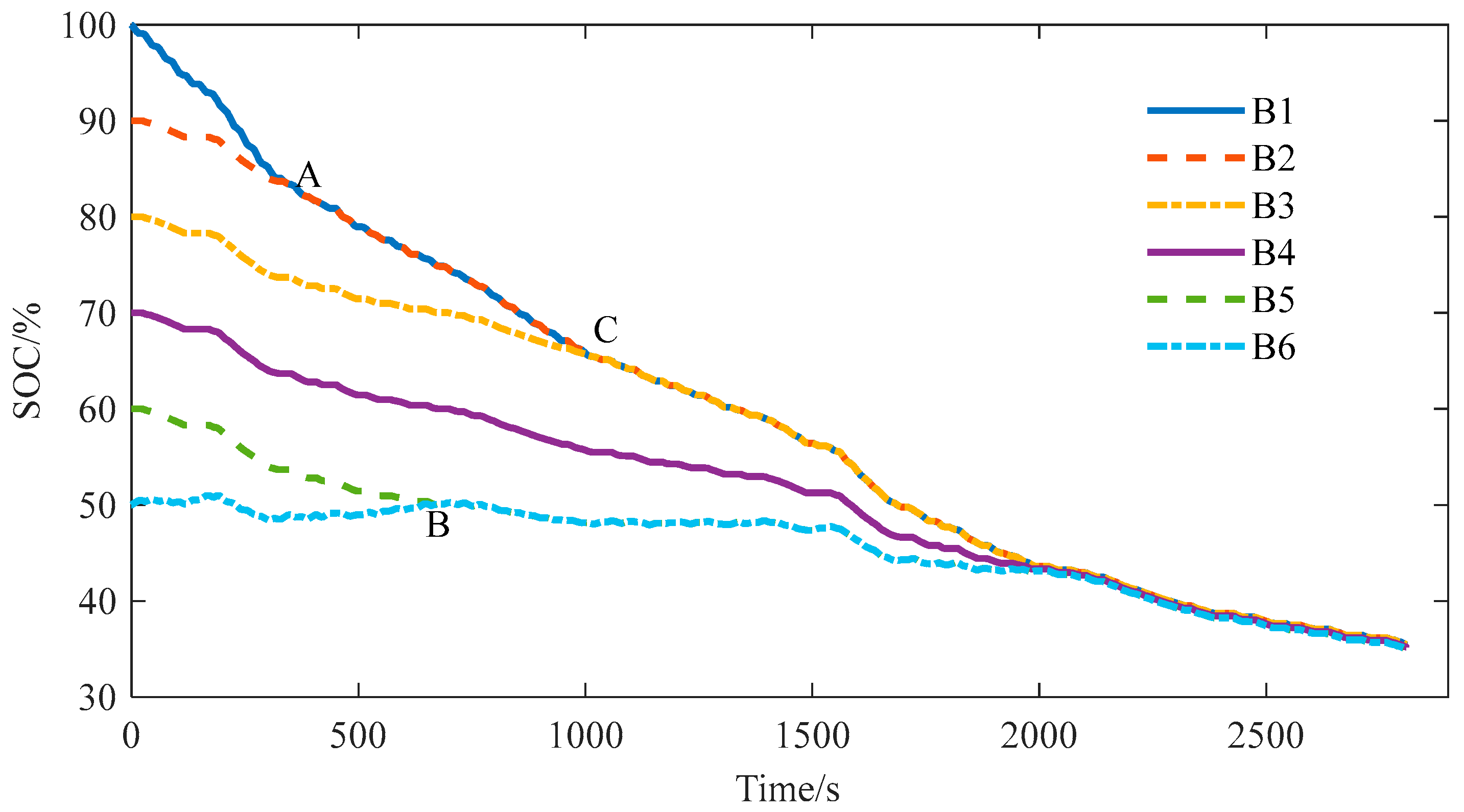
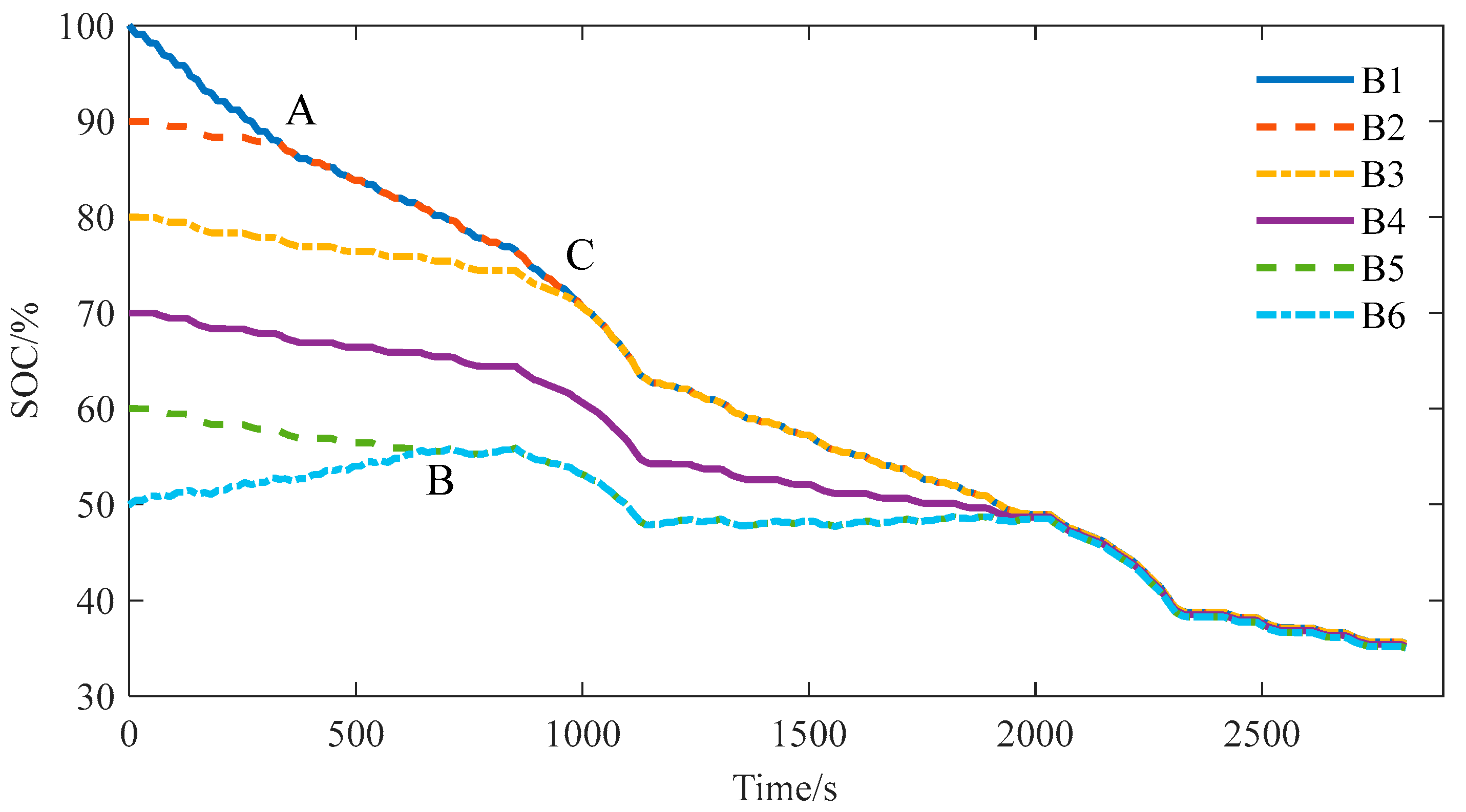
In order to prove the effectiveness of the equalization system, two working conditions of UDDS and NEDC are loaded in the equalization system. After setting the initial SOC of the battery, the extreme value of the battery SOC satisfies the equalization opening condition, and the equalization function is turned on. In the equilibrium process of the two working conditions, at point A, batteries B1 and B2 transfer the energy to battery B6; at point B, the SOC of battery B5 is the same as that of battery B6, which is balanced by a high-power battery. At point C, batteries B1, B2, and B3 transfer the energy to the low-power battery together. The equalization process under UDDS condition is shown in
Figure 20, and the equalization process under NEDC condition is shown in
Figure 21.
At 1980 s, the equalization process under the UDDS condition is completed, and the SOC range of the battery pack after discharge is 0.5%. The SOC of the high-power battery is reduced by 36 Ah due to equalization, and the SOC of the low-power battery is increased by 28.2 Ah due to equalization, and the equalization efficiency is 75%.
At 1970s, the equalization process under the NEDC condition is completed, and the SOC range of the battery pack after discharge is 0.49%. The SOC of the high-capacity batteries decreases by 34.2 Ah due to equalization, and the SOC of the low-capacity batteries increases by 26.4 Ah due to equalization. The equalization efficiency is 74%.
Table 7 shows the equilibrium results under the above two working conditions.
The equalization scheme used in this paper has advantages in many aspects compared with the “peak clipping and valley filling“ type equalization method and can achieve the equalization effect under complex working conditions. Through the equalization results, it can be found that the efficiency, time, and energy consumed by the equalization of this method are improved, which can better meet the equalization effect.
7. Conclusions
Based on the equalization topology of the bidirectional flyback DC–DC converter, this paper proposes an active equalization topology, which makes the equalization process only occur between batteries with different power and can realize the equalization between any batteries. Combined with the SOC estimation algorithm, the simulation model of the equalization control system is built and verified under various conditions. By comparison with the “peak clipping and valley filling” type equalization and analyzing the simulation results, the equalization efficiency of the battery equalization system in the charging state, discharge state, and shelving state can reach about 80%, which is higher than the “peak clipping and valley filling” type equalization; the energy consumed in the equilibrium is lower than that in the “peak load shifting“ equilibrium; the equilibrium time is faster. By comparing the simulation results, it can be proven that the equalization control system has a better equalization effect and can better solve the inconsistency of the battery at different stages.
Author Contributions
Conceptualization, S.Q.; software, S.Q.; validation, H.W. and S.Q.; formal analysis, D.Q.; writing—original draft preparation, S.Q.; writing—review and editing, D.Q.; visualization, T.W. and J.C.; supervision, D.Q.; project administration, T.W.; funding acquisition, D.Q. All authors have read and agreed to the published version of the manuscript.
Funding
This research was funded the 2022 Henan Province major science and Technology Special project “Fuel Cell Vehicle and Key Components Technology Research and Demonstration Application” (221100240200).
Data Availability Statement
Data are contained within the article.
Conflicts of Interest
The authors declare no conflict of interest.
References
- Muniamuthu, S.; Arjun, S.; Jalapathy, M.Y. Review on Electric Vehicles. Rev. Electr. Veh. 2018, 8, 557–566. [Google Scholar]
- Alexander, A.; Wladislaw, W.; Andrea, M. Critical review of on-board capacity estimation techniques for lithium-ion batteries in electric and hybrid electric vehicles. J. Power Sources 2015, 281, 114–130. [Google Scholar]
- Song, D.; Shi, F.; Liu, W. Review of Lithium Battery Equalization Control Methods. J. Phys. Conf. Ser. 2020, 1449, 012087. [Google Scholar] [CrossRef] [Green Version]
- Xiang, J.; Cui, N.; Shang, Y. Modularized charge equalizer using multiwinding transformers for Lithium-ion battery system. In Proceedings of the IEEE Conference and Expo Transportation Electrification Asia-Pacific, Beijing, China, 31 August–3 September 2014. [Google Scholar]
- Yang, D.; Li, S.; Qi, G. A bidirectional flyback cell equalizer for series-connected lithium iron phosphate batteries. In Proceedings of the 2015 6th International Conference on Power Electronics Systems and Applications, Hong Kong, China, 15–17 December 2015. [Google Scholar]
- Li, J.; Huang, Z.; Zhou, W. Battery Equalization System with Peaking Shaving and Vallry Filling Mode Based on Fuzzy PID Control. J. Chongqing Jiaotong Univ. (Nat. Sci.) 2020, 39, 7. [Google Scholar]
- Guo, X.; Geng, J.; Liu, Z. A Flyback Converter-Based Hybrid Balancing Method for Series-Connected Battery Pack in Electric Vehicles. IEEE Trans. Veh. Technol. 2021, 70, 6626–6635. [Google Scholar] [CrossRef]
- Zhao, C.; Liu, S.; Fan, B. State of Charge Balancing Control for Battery System Based on the ReconFigurable Converter. In Proceedings of the 2021 IEEE 5th Conference on Energy Internet and Energy System Integration, Taiyuan, China, 22–24 October 2021; pp. 4215–4220. [Google Scholar]
- Turksoy, A.; Teke, A.; Alkaya, A. A comprehensive overview of the dc-dc converter-based battery charge balancing methods in electric vehicles. Renew. Sustain. Energy Rev. 2020, 133, 110274. [Google Scholar] [CrossRef]
- Li, Y.; Xu, J.; Mei, X. A Unitized Multiwinding Transformer-Based Equalization Method for Series-Connected Battery Strings. IEEE Trans. Power Electron. 2019, 34, 11981–11989. [Google Scholar] [CrossRef]
- Zheng, Z.; Wang, K.; Xu, L. A Hybrid Cascaded Multilevel Converter for Battery Energy Management Applied in Electric Vehicles. IEEE Trans. Power Electron. 2014, 29, 3537–3546. [Google Scholar] [CrossRef]
- Wang, Y.; Zhang, C.; Chen, Z.; Xie, J.; Zhang, X. A novel active equalization method for lithium-ion batteries in electric vehicles. Appl. Energy 2015, 145, 36–42. [Google Scholar] [CrossRef]
- Chen, Y.; Liu, X.; Fathy, H.K.; Zou, J.; Yang, S. A graph-theoretic framework for analyzing the speeds and efficiencies of battery pack equalization circuits. Int. J. Electr. Power Energy Syst. 2018, 98, 85–99. [Google Scholar] [CrossRef]
- Zhang, E.; Xu, C.; Liu, G. An active battery equalization scheme for Lithium iron phosphate batteries. Energy Procedia 2019, 158, 4702–4707. [Google Scholar] [CrossRef]
- Zhang, Z.; Zhang, L.; Hu, L.; Huang, C. Active cell balancing of Lithium-ion battery pack based on average state of charge. Int. J. Energy Res. 2020, 44, 2535–2548. [Google Scholar] [CrossRef]
- He, H.; Xiong, R.; Zhang, X. State-of-Charge Estimation of the Lithium-Ion Battery Using an Adaptive Extended Kalman Filter Based on an Improved Thevenin Model. IEEE Trans. Veh. Technol. 2011, 60, 1461–1469. [Google Scholar]
- Gao, Y.; Huang, R.; Qin, D. State-of-Charge Estimation of Lithium-ion Battery Based on Capacity Degradation Model Considering the Dynamic Currents and Temperatures. Int. J. Electrochem. Sci. 2021, 16, 210424. [Google Scholar] [CrossRef]
- Yan, X.; Guo, Y.; Cui, Y. Electric Vehicle Battery SOC Estimation based on GNL Model Adaptive Kalman Filter. J. Phys. Conf. Ser. 2018, 1087, 052027. [Google Scholar] [CrossRef]
- Wu, T.; Wu, X.; Cui, Z.; Li, X.; Du, J.; Liu, Y. Research on equalization strategy of lithium-ion batteries based on fuzzy logic control. Energy Storage 2021, 40, 102722. [Google Scholar] [CrossRef]
- Xiong, R.; Sun, F. A data-driven multi-scale extended Kalman filtering based parameter and state estimation approach of lithium-ion polymer battery in electric vehicles. Appl. Energy 2014, 113, 463–476. [Google Scholar] [CrossRef]
- Wang, Y.; Zhang, C.; Chen, Z. A method for state-of-charge estimation of Li-ion batteries based on multi-model switching strategy. Appl. Energy 2015, 137, 427–434. [Google Scholar] [CrossRef]
- Cheng, Z.; Allafi, W.; Dinh, Q. Online estimation of battery equivalent circuit model parameters and state of charge using decoupled least squares technique. Energy 2018, 142, 678–688. [Google Scholar]
- Luo, S.; Qin, D.; Wu, H. Multi-Cell-to-Multi-Cell Battery Equalization in Series Battery Packs Based on Variable Duty Cycle. Energies 2022, 15, 3263. [Google Scholar] [CrossRef]
- Han, J.; Yang, S.; Liu, X.; Yang, W. An Active Direct Cell-to-cell Balancing Circuit Continuous Current Mode for Series Connected Batteries. Energies 2019, 12, 3978. [Google Scholar] [CrossRef] [Green Version]
- Qin, S.; Qin, D.; Wu, H. State of Charge estimation of lithium-ion power battery based on online parameter Identification method and BP neural network. Int. J. Electrochem. Sci. 2022, 17, 2. [Google Scholar] [CrossRef]
- Mahammad, H.; Pin, K. Charge Equalization Controller Algorithm for Series-Connected Lithium-Ion Battery Storage Systems: Modeling and Applications. Energies 2022, 15, 3263. [Google Scholar]
Figure 1.
“Peak cutting“ equilibrium process. (a) “Peak cutting” equilibrium process I. (b) “Peak cutting” equilibrium process II.
Figure 1.
“Peak cutting“ equilibrium process. (a) “Peak cutting” equilibrium process I. (b) “Peak cutting” equilibrium process II.
Figure 2.
“Valley filling” equalization process. (a) “Valley filling” equalization process I. (b) “Valley filling“ equalization process II.
Figure 2.
“Valley filling” equalization process. (a) “Valley filling” equalization process I. (b) “Valley filling“ equalization process II.
Figure 3.
Balanced topology based on bidirectional flyback DC converter.
Figure 3.
Balanced topology based on bidirectional flyback DC converter.
Figure 4.
The working process of equalization mode 1. (a) Battery B1 discharges to primary winding. (b) Primary winding discharges to battery B6.
Figure 4.
The working process of equalization mode 1. (a) Battery B1 discharges to primary winding. (b) Primary winding discharges to battery B6.
Figure 5.
Working process of equalization mode 2. (a) Battery B6 discharges to primary winding. (b) Primary winding discharges to battery B2. (c) Battery B1 discharges to the primary winding.
Figure 5.
Working process of equalization mode 2. (a) Battery B6 discharges to primary winding. (b) Primary winding discharges to battery B2. (c) Battery B1 discharges to the primary winding.
Figure 6.
Working process of equalization mode 3. (a) Battery B1 discharges to primary winding. (b) Primary winding discharges to battery B2. (c) Battery B6 discharges to primary winding. (d) Primary winding discharges to battery.
Figure 6.
Working process of equalization mode 3. (a) Battery B1 discharges to primary winding. (b) Primary winding discharges to battery B2. (c) Battery B6 discharges to primary winding. (d) Primary winding discharges to battery.
Figure 7.
Voltage variation under constant current discharge condition.
Figure 7.
Voltage variation under constant current discharge condition.
Figure 8.
Voltage SOC changes under UDDS conditions. (a) Voltage under UDDS condition. (b) SOC under UDDS condition.
Figure 8.
Voltage SOC changes under UDDS conditions. (a) Voltage under UDDS condition. (b) SOC under UDDS condition.
Figure 9.
Voltage variation under constant current condition.
Figure 9.
Voltage variation under constant current condition.
Figure 10.
Equivalent circuit model of second-order RC network.
Figure 10.
Equivalent circuit model of second-order RC network.
Figure 11.
Balancing strategy flow chart.
Figure 11.
Balancing strategy flow chart.
Figure 12.
Bidirectional flyback DC–DC converter module.
Figure 12.
Bidirectional flyback DC–DC converter module.
Figure 13.
Battery SOC estimation module. (a) Equivalent circuit model section. (b) The online parameter identification part of the FFRLS method. (c) EKF estimated SOC section.
Figure 13.
Battery SOC estimation module. (a) Equivalent circuit model section. (b) The online parameter identification part of the FFRLS method. (c) EKF estimated SOC section.
Figure 14.
Equalization process in charging state.
Figure 14.
Equalization process in charging state.
Figure 15.
Equilibrium results of peak clipping scheme under charging condition.
Figure 15.
Equilibrium results of peak clipping scheme under charging condition.
Figure 16.
Equalization process in discharge state.
Figure 16.
Equalization process in discharge state.
Figure 17.
Equilibrium results of filling valley scheme.
Figure 17.
Equilibrium results of filling valley scheme.
Figure 18.
The equilibrium result of the static state.
Figure 18.
The equilibrium result of the static state.
Figure 19.
Equilibrium results of peak clipping scheme under Standing condition.
Figure 19.
Equilibrium results of peak clipping scheme under Standing condition.
Figure 20.
SOC change process under UDDS condition.
Figure 20.
SOC change process under UDDS condition.
Figure 21.
SOC change process under NEDC condition.
Figure 21.
SOC change process under NEDC condition.
Table 1.
The terminal voltage of the battery when the SOC is 0–20%.
Table 1.
The terminal voltage of the battery when the SOC is 0–20%.
| SOC/% | 20 | 18 | 16 | 14 | 12 | 10 | 8 | 6 | 4 | 2 |
| Voltage/V | 3.144 | 3.137 | 3.129 | 3.121 | 3.112 | 3.099 | 3.076 | 3.038 | 2.977 | 2.874 |
| Voltage variation/mV | 7 | 7 | 8 | 8 | 9 | 13 | 23 | 38 | 61 | 103 |
Table 2.
Battery parameters.
Table 2.
Battery parameters.
| Type | Voltage Range | Rated Capacity | Working Temperature | Standard Charge Discharge Current |
|---|
| lithium iron phosphate battery | 2.5 V–4.2 V | 60 AH | −20–50 ℃ | 30A |
Table 3.
Initial SOC of battery.
Table 3.
Initial SOC of battery.
| Battery | B1 | B2 | B3 | B4 | B5 | B6 |
|---|
| Initial SOC/% | 70 | 60 | 50 | 40 | 30 | 20 |
Table 4.
Equilibrium result of charging state.
Table 4.
Equilibrium result of charging state.
| | SOC Range
/% | Power Consumed at Equilibrium
Completion
/Ah | Balancing Efficiency
/% | Time
/s |
|---|
| Scheme of this article | 0.44 | 27 | 79 | 1900 |
| Peak shaving equilibrium | 0.48 | 60 | 73 | 2320 |
Table 5.
Equilibrium result of discharging state.
Table 5.
Equilibrium result of discharging state.
| | SOC Range
/% | Power Consumed at Equilibrium Completion/Ah | Balancing Efficiency
/% | Time
/s |
|---|
| Scheme of this article | 0.49 | 33.6 | 80 | 2050 |
| Valley filling equilibrium | 0.5 | 65 | 61.5 | 2800 |
Table 6.
Equilibrium result of static state.
Table 6.
Equilibrium result of static state.
| | SOC Range
/% | Power Consumed at Equilibrium Completion/Ah | Balancing Efficiency
/% | Time
/s |
|---|
| Scheme of this article | 0.47 | 35.4 | 82 | 1770 |
| Peak clipping equilibrium | 0.49 | 58 | 69 | 2620 |
Table 7.
Equilibrium results under NEDC and UDDS conditions.
Table 7.
Equilibrium results under NEDC and UDDS conditions.
| | SOC Range
/% | More Energy Released than without Equilibrium
/Ah | Power Consumed at Equilibrium Completion/Ah | Balancing Efficiency
/% | Time
/s |
|---|
| UDDS | 0.5% | 72 Ah | 36 Ah | 75% | 1980s |
| NEDC | 0.49% | 63 Ah | 34.2 Ah | 74% | 1970s |
| Publisher’s Note: MDPI stays neutral with regard to jurisdictional claims in published maps and institutional affiliations. |
© 2022 by the authors. Licensee MDPI, Basel, Switzerland. This article is an open access article distributed under the terms and conditions of the Creative Commons Attribution (CC BY) license (https://creativecommons.org/licenses/by/4.0/).


