
A Review of Simulation Models of Heat Extraction for a Geothermal Reservoir in an Enhanced Geothermal System

Abstract
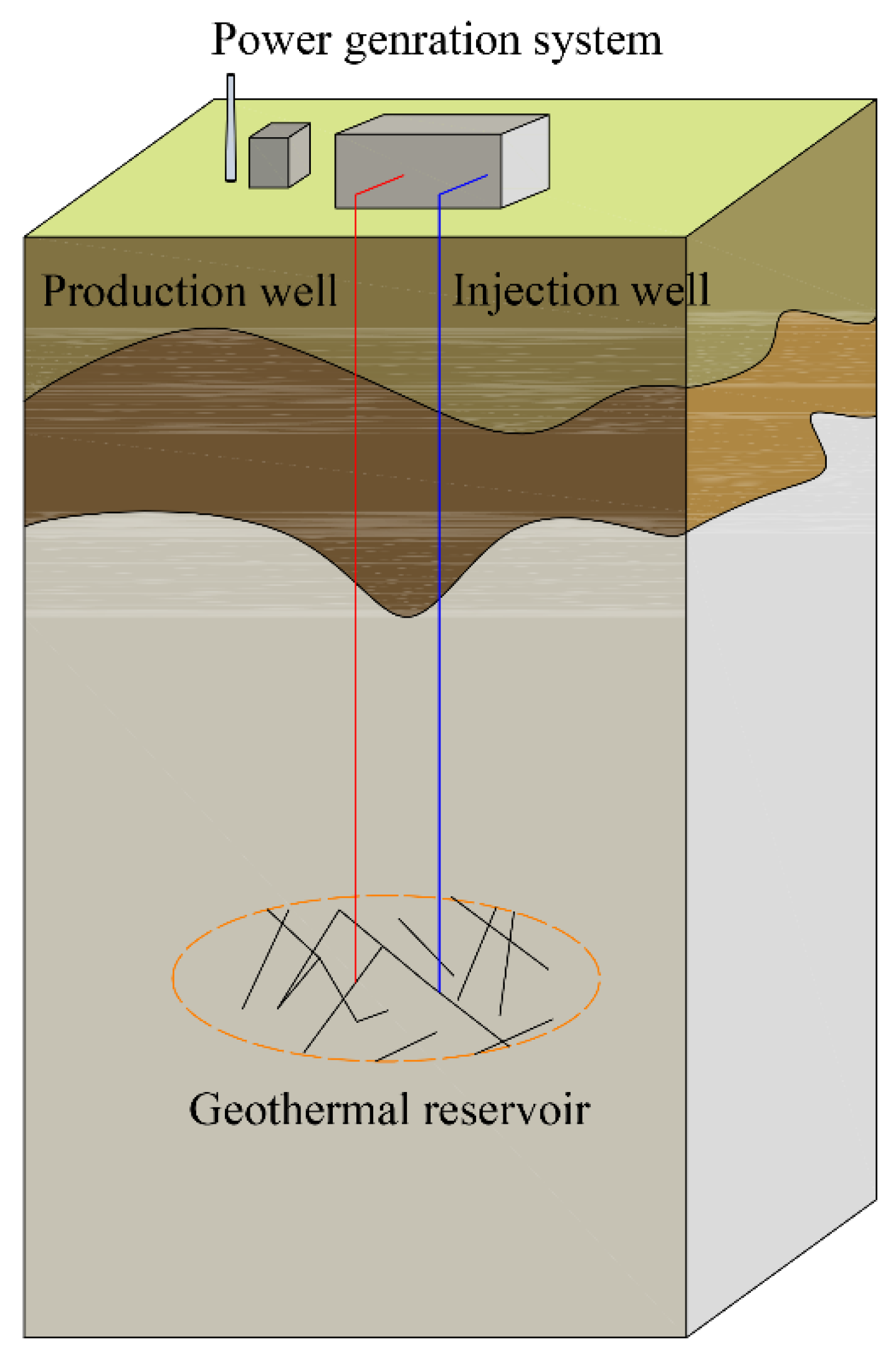
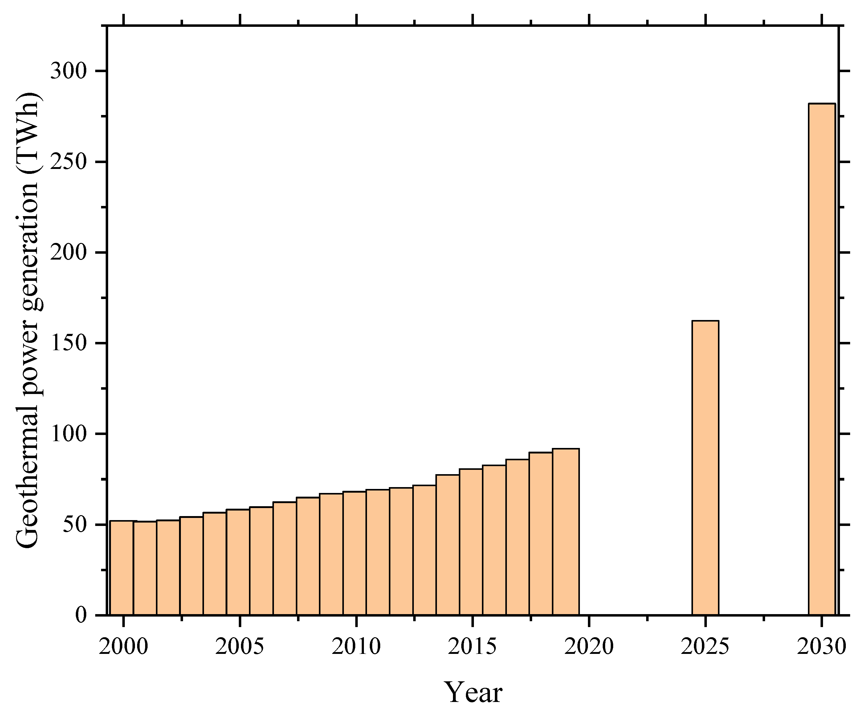
:1. Introduction
2. The Applications of Enhanced Geothermal System in Porosity Models
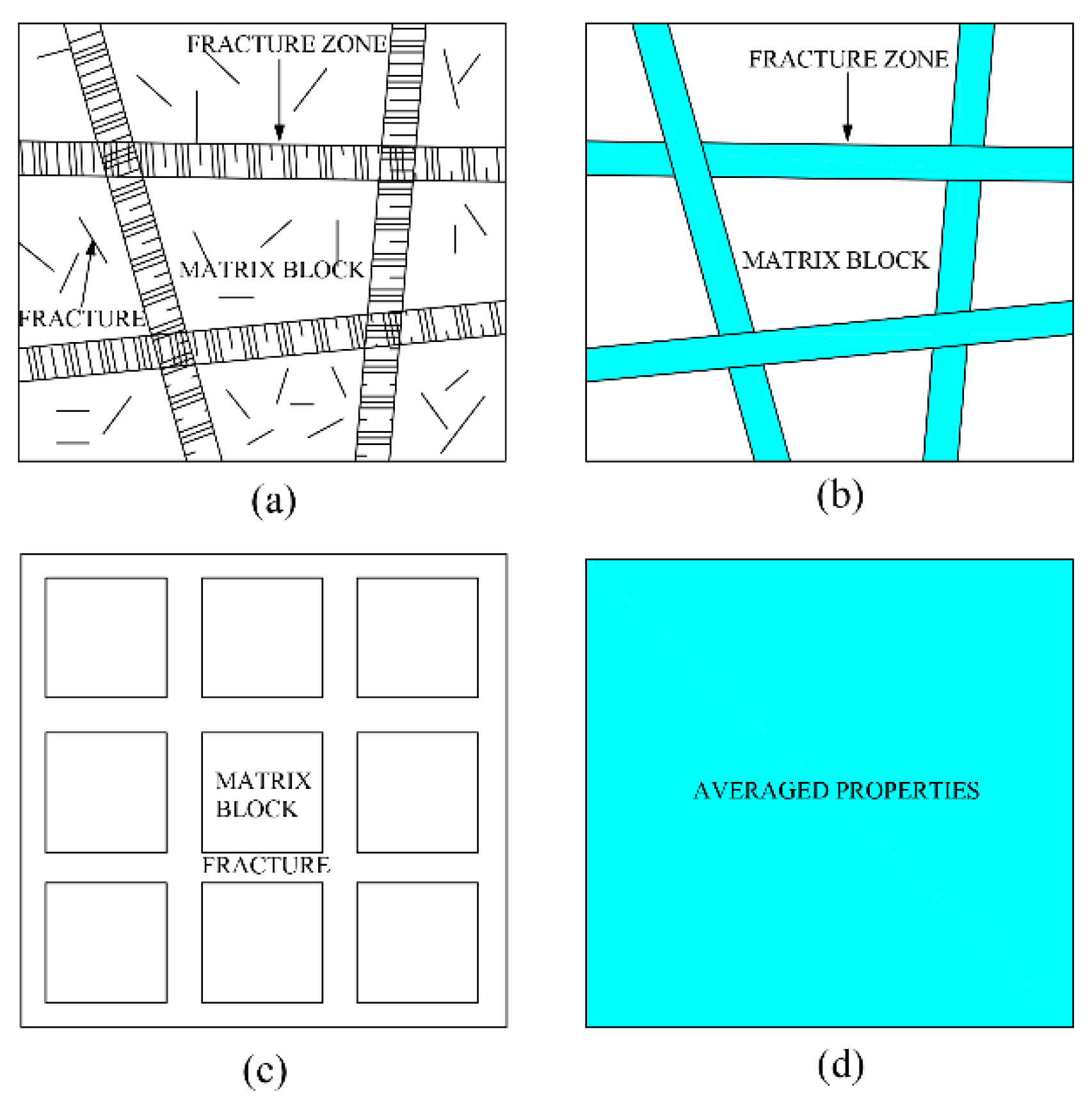
2.1. The Single-Porosity Model
2.2. The Dual-Porosity Model
2.3. The Multi-Porosity Model
- The combination between the multi-porosity model and fracture network in geothermal reservoirs has received extensive attention currently, however, the original intention of the porosity model is to simplify the complicated fracture network; thus, this combination has again complicated the geothermal reservoir. This is mainly due to the improvement of computer computing performance. Due to some parameters in porosity models with statistical features, the selection of these parameters values is the key issue in the establishment of numerical simulations. The parameters with statistical features are not simply equal to the actual experimental value for geothermal reservoirs.
- Porosity models have neglected many characteristics of geothermal reservoirs, so it is difficult to explain a given heat transfer or fluid flow in a geothermal reservoir unless the N-S equation is employed. Porosity models are more applicable in engineering fields.
- How to make actual distribution of fracture in geothermal reservoir equivalent into the numerical model is the key factor for numerical simulation.
3. The Numerical Model for Fracture Networks in a Reservoir
3.1. Conventional Fracture Theory
3.2. Stimulated Reservoir Volume
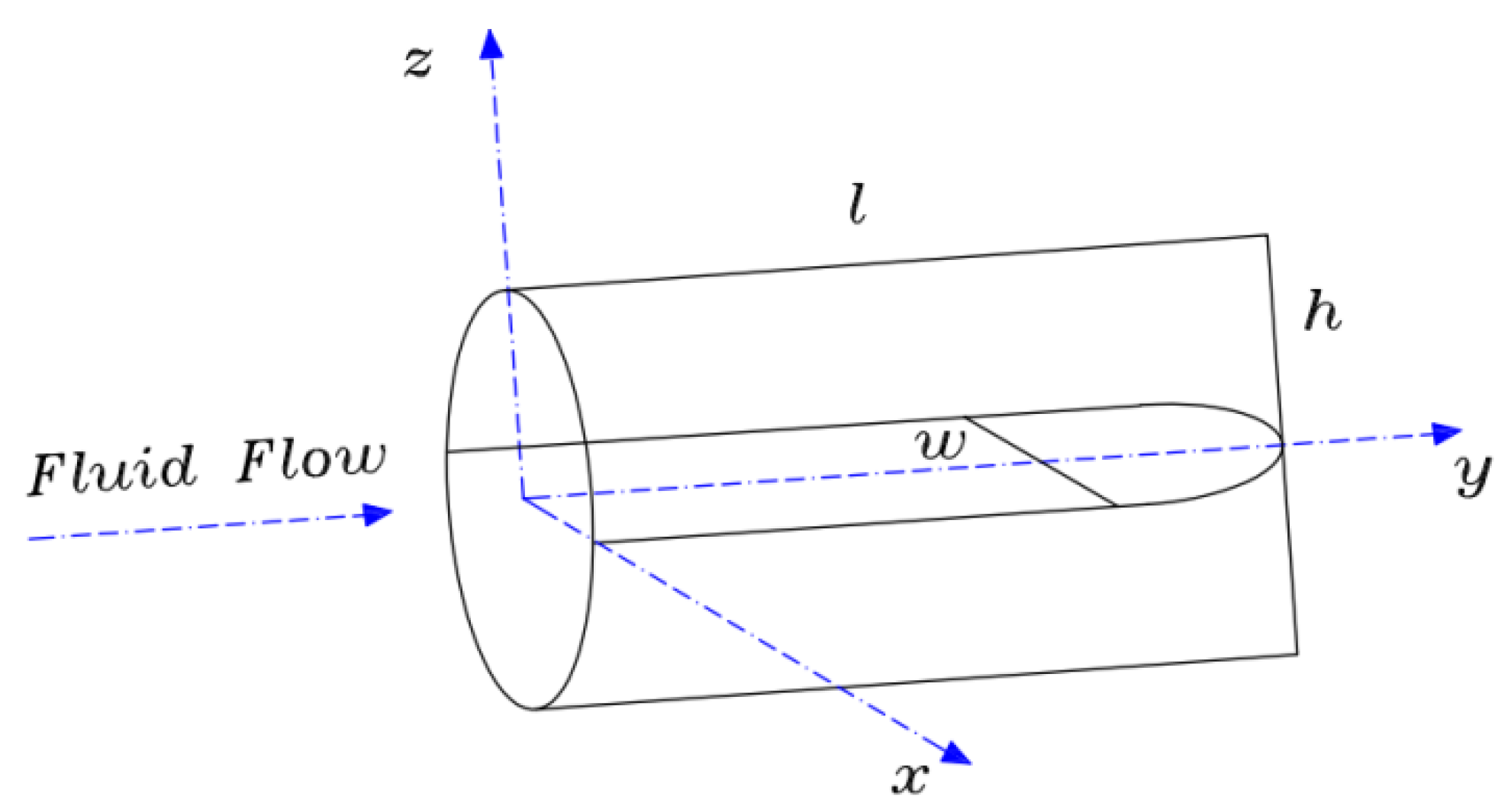
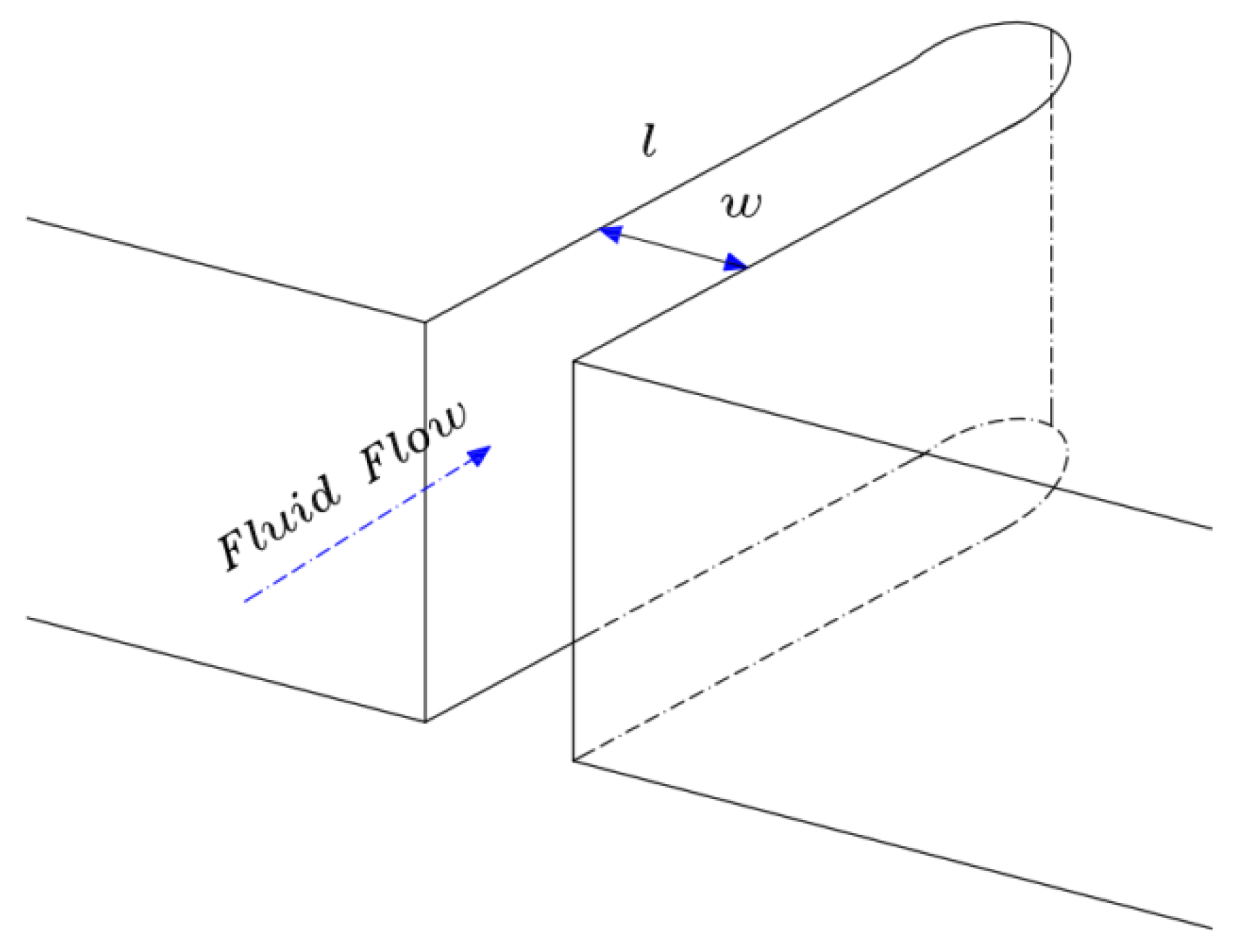
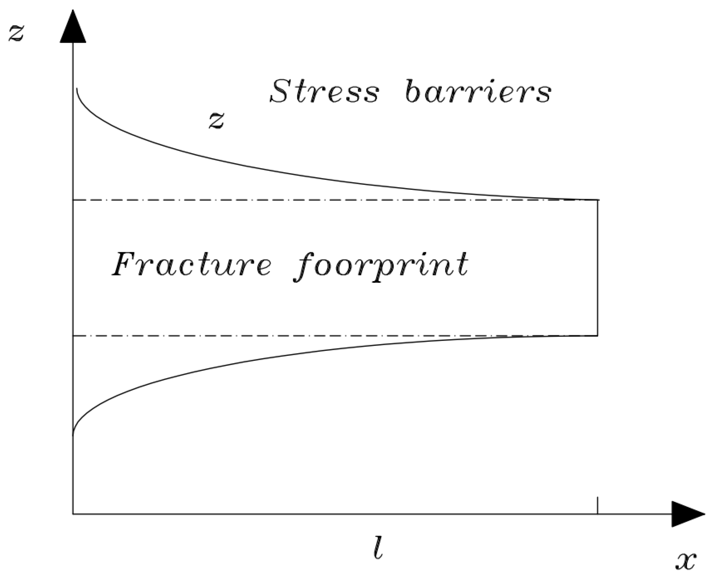
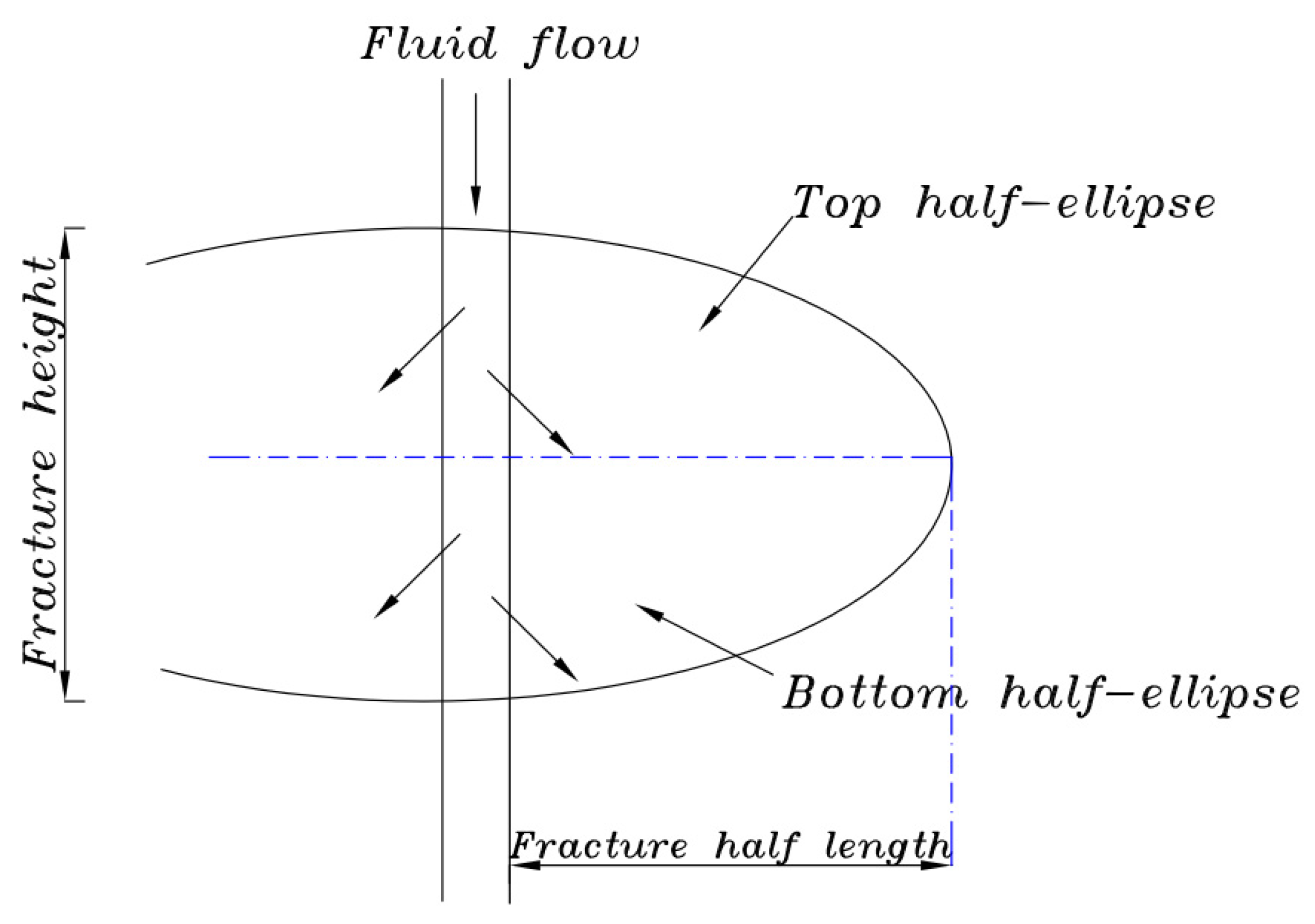
4. The Numerical Model of Hydraulic Fracturing
5. General Models for Geothermal Reservoir in EGS
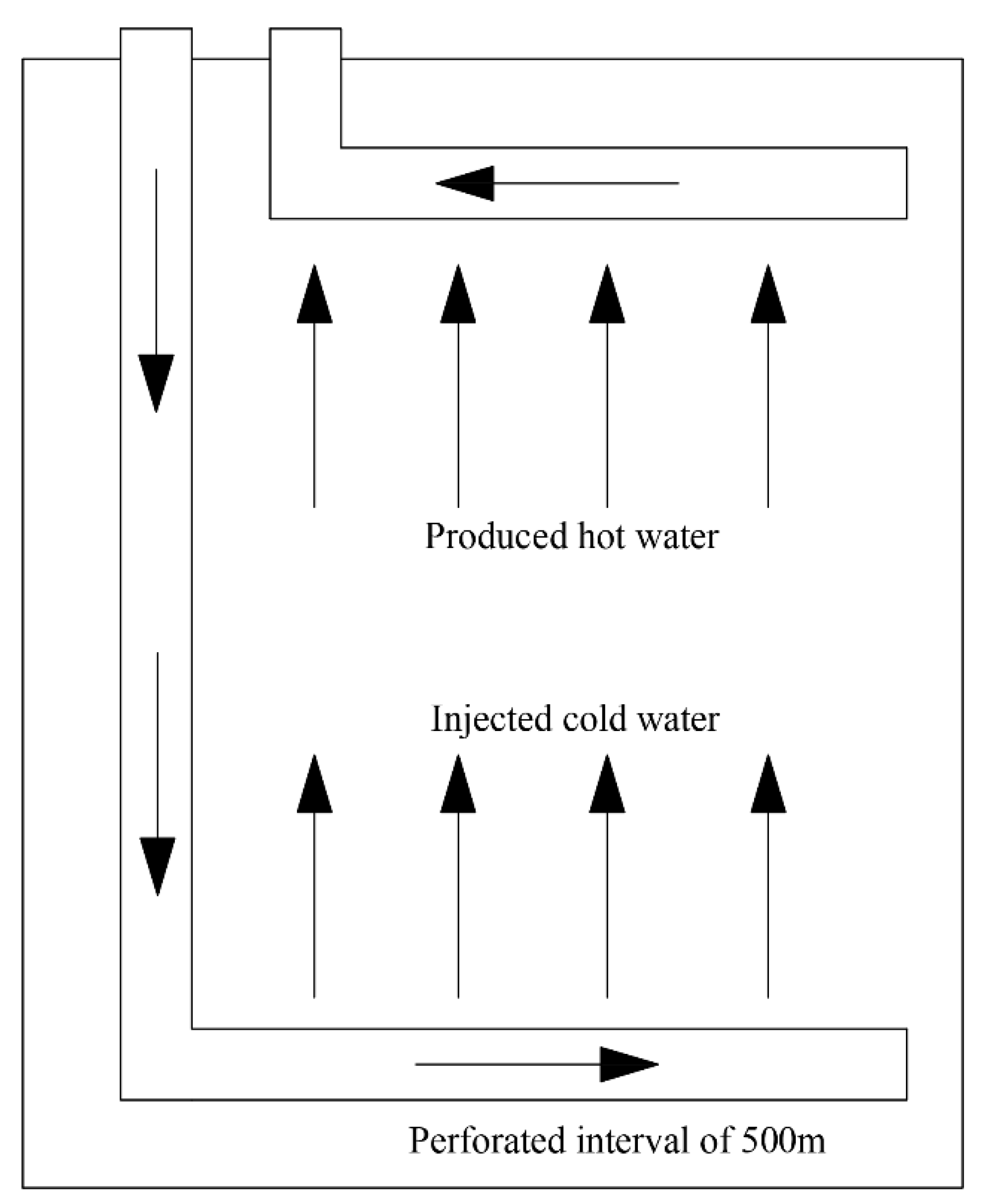
5.1. Physical Model of Geothermal Reservoir and Hydraulic Fracture
5.2. Mathematical Model of Geothermal Reservoir Coupled with Hydraulic Fracture
5.3. Meshing, Discretization and Software
6. Conclusions
- On the basis of the comparison of different numerical models, the porosity model has an advantage when a model only considers the impact of heat transfer for the injection well and production well, but the complexity of fractures is difficult to represent based on the porosity model.
- The selection of these parameters’ values in the porosity model is the key issue in the establishment of numerical simulations. The parameters with statistical features are not simply equal to the actual experimental value for a geothermal reservoir.
- For the fracture-generation technology, the stimulated reservoir volume technology has the more accuracy than conventional fracture theory when the multi-scale fracture propagations are described. The revised conventional fracture theory, such as in the P3D model, has introduced the high growth for a single fracture to describe the three-dimensional model of fracture propagation. Due to the stimulated reservoir volume technology based on the statistics data, this model can represent the characteristics of the geothermal reservoirs if the geological data are detailed.
- After the comparison between different numerical models of hydraulic fracturing, since the finite element method can provide the same mesh and node for fracture propagation and fluid flow in fracture, this model can reduce the computational time and resources. However, all numerical models need to be regenerated in the mesh to calculate the fracture propagation, and this step will occupy large computational resources.
- The development technology for enhanced geothermal system is based on the experience of the oil or gas industry. In the oil or gas industry, the fluid flow in the reservoir is the main research focus. These mature numerical models have proven the effectiveness for fracture propagation and fluid flow. In contrast, the heat transfer is the most important factor for geothermal reservoirs, therefore, the numerical model for an enhanced geothermal system needs to include the heat transfer, fluid flow, and fracture propagation. Although the porosity model can calculate the heat transfer process to satisfy industrial demand, this equivalent model cannot provide the details of geothermal reservoirs. Thus, if a developed model based on the oil or gas industry contains the heat transfer process, this model can provide a precise description for geothermal reservoirs.
Funding
Acknowledgments
Conflicts of Interest
References
- Haenel, R. Handbook of geothermal energy: By L.M. Edwards, G.V. Chilingar, H.H. Rieke III, W.H. Fertl (Editors). Gulf Publishing Company, Houston, 1982. (distr. in U.K. and W. Europe by MTP Press). ix + 613 pp., £56.25 (hardback). J. Volcanol. Geoth. Res. 1983, 19, 186–187. [Google Scholar] [CrossRef]
- Zhou, D.; Tatomir, A.; Niemi, A.; Tsang, C.; Sauter, M. Study on the influence of randomly distributed fracture aperture in a fracture network on heat production from an enhanced geothermal system (EGS). Energy 2022, 250, 123781. [Google Scholar] [CrossRef]
- Liu, G.; Zhou, C.; Rao, Z.; Liao, S. Impacts of fracture network geometries on numerical simulation and performance prediction of enhanced geothermal systems. Renew. Energy 2021, 171, 492–504. [Google Scholar] [CrossRef]
- Zhang, B.; Qu, Z.; Guo, T.; Sheng, M.; Chen, M.; Wang, J.; Wang, Y.; Guo, C. Coupled thermal-hydraulic investigation on the heat extraction performance considering a fractal-like tree fracture network in a multilateral well enhanced geothermal system. Appl. Therm. Eng. 2022, 208, 118221. [Google Scholar] [CrossRef]
- Xie, J.; Wang, J.; Liu, X. The role of fracture networks randomness in thermal utilization of enhanced geothermal system. Int. Commun. Heat Mass Transf. 2021, 126, 105414. [Google Scholar] [CrossRef]
- Zheng, S.; Li, S.; Zhang, D. Fluid and heat flow in enhanced geothermal systems considering fracture geometrical and topological complexities: An extended embedded discrete fracture model. Renew. Energy 2021, 179, 163–178. [Google Scholar] [CrossRef]
- Zhang, X.; Huang, Z.; Lei, Q.; Yao, J.; Gong, L.; Yang, W.; Yan, X.; Li, Y. Improving heat extraction performance of enhanced geothermal systems: Insights from critical fracture network parameter and multi-objective optimization method. Appl. Therm. Eng. 2022, 213, 118671. [Google Scholar] [CrossRef]
- Li, L.; Guo, X.; Zhou, M.; Xiang, G.; Zhang, N.; Wang, Y.; Wang, S.; Pagou, A. The Investigation of Fracture Networks on Heat Extraction Performance for an Enhanced Geothermal System. Energies 2021, 14, 1635. [Google Scholar] [CrossRef]
- IEA Renewables 2020. Available online: https://www.iea.org/reports/renewables-2020 (accessed on 1 November 2020).
- Gao, X.; Zhang, Y.; Huang, Y.; Ma, Y.; Zhao, Y.; Liu, Q. Study on heat extraction considering the number and orientation of multilateral wells in a complex fractured geothermal reservosir. Renew. Energy 2021, 177, 833–852. [Google Scholar] [CrossRef]
- Rinaldi, A.P.; Rutqvist, J. Joint opening or hydroshearing? Analyzing a fracture zone stimulation at Fenton Hill. Geothermics 2019, 77, 83–98. [Google Scholar] [CrossRef] [Green Version]
- Norbeck, J.H.; McClure, M.W.; Horne, R.N. Field observations at the Fenton Hill enhanced geothermal system test site support mixed-mechanism stimulation. Geothermics 2018, 74, 135–149. [Google Scholar] [CrossRef]
- Brown, D.W.; Duchane, D.V. Scientific progress on the Fenton Hill HDR project since 1983. Geothermics 1999, 28, 591–601. [Google Scholar] [CrossRef]
- He, R.; Rong, G.; Tan, J.; Phoon, K.; Quan, J. Numerical evaluation of heat extraction performance in enhanced geothermal system considering rough-walled fractures. Renew. Energy 2022, 188, 524–544. [Google Scholar] [CrossRef]
- Mahmoodpour, S.; Singh, M.; Turan, A.; Bär, K.; Sass, I. Simulations and global sensitivity analysis of the thermo-hydraulic-mechanical processes in a fractured geothermal reservoir. Energy 2022, 247, 123511. [Google Scholar] [CrossRef]
- Mahmoodpour, S.; Singh, M.; Bär, K.; Sass, I. Thermo-hydro-mechanical modeling of an enhanced geothermal system in a fractured reservoir using carbon dioxide as heat transmission fluid- A sensitivity investigation. Energy 2022, 254, 124266. [Google Scholar] [CrossRef]
- Zheng, J.; Li, P.; Dou, B.; Fan, T.; Tian, H.; Lai, X. Impact research of well layout schemes and fracture parameters on heat production performance of enhanced geothermal system considering water cooling effect. Energy 2022, 255, 124496. [Google Scholar] [CrossRef]
- Zhixue, S.; Jiang, C.; Wang, X.; Zhou, W.; Lei, Q. Combined Effects of Thermal Perturbation and In-situ Stress on Heat Transfer in Fractured Geothermal Reservoirs. Rock Mech. Rock Eng. 2021, 54, 1–17. [Google Scholar]
- Liu, J.; Xue, Y.; Zhang, Q.; Wang, H.; Wang, S. Coupled thermo-hydro-mechanical modelling for geothermal doublet system with 3D fractal fracture. Appl. Therm. Eng. 2022, 200, 117716. [Google Scholar] [CrossRef]
- de Hoop, S.; Voskov, D.V.; Bertotti, G.; Barnhoorn, A. An Advanced Discrete Fracture Methodology for Fast, Robust, and Accurate Simulation of Energy Production From Complex Fracture Networks. Water Resour. Res. 2022, 58, e2021WR030743. [Google Scholar] [CrossRef]
- Guo, T.; Zhang, Y.; Zhang, W.; Niu, B.; He, J.; Chen, M.; Yu, Y.; Xiao, B.; Xu, R. Numerical simulation of geothermal energy productivity considering the evolution of permeability in various fractures. Appl. Therm. Eng. 2022, 201, 117756. [Google Scholar] [CrossRef]
- Cao, M.; Hirose, S.; Sharma, M.M. Factors controlling the formation of complex fracture networks in naturally fractured geothermal reservoirs. J. Petrol. Sci. Eng. 2022, 208, 109642. [Google Scholar] [CrossRef]
- Aliyu, M.D.; Finkbeiner, T.; Chen, H.; Archer, R.A. A three-dimensional investigation of the thermoelastic effect in an enhanced geothermal system reservoir. Energy 2022, 125466. [Google Scholar] [CrossRef]
- Ji, J.; Song, X.; Xu, F.; Song, G.; Shi, Y.; Wang, G.; Song, Z.; Li, S. Effects of variable thermophysical properties of water on the heat extraction of an enhanced geothermal system: A numerical case study. Appl. Therm. Eng. 2022, 217, 119050. [Google Scholar] [CrossRef]
- Wang, G.; Ma, X.; Song, X.; Li, G. Modeling flow and heat transfer of fractured reservoir: Implications for a multi-fracture enhanced geothermal system. J. Clean. Prod. 2022, 365, 132708. [Google Scholar] [CrossRef]
- Bataillé, A.; Genthon, P.; Rabinowicz, M.; Fritz, B. Modeling the coupling between free and forced convection in a vertical permeable slot: Implications for the heat production of an Enhanced Geothermal System. Geothermics 2006, 35, 654–682. [Google Scholar] [CrossRef]
- Zhang, J.; Xie, J. Effect of reservoir’s permeability and porosity on the performance of cellular development model for enhanced geothermal system. Renew. Energy 2020, 148, 824–838. [Google Scholar] [CrossRef]
- Song, G.; Song, X.; Ji, J.; Wu, X.; Li, G.; Xu, F.; Shi, Y.; Wang, G. Evolution of fracture aperture and thermal productivity influenced by chemical reaction in enhanced geothermal system. Renew. Energy 2022, 186, 126–142. [Google Scholar] [CrossRef]
- Zhang, Y.; Zhang, Y.; Zhou, L.; Lei, Z.; Guo, L.; Zhou, J. Reservoir stimulation design and evaluation of heat exploitation of a two-horizontal-well enhanced geothermal system (EGS) in the Zhacang geothermal field, Northwest China. Renew. Energy 2022, 183, 330–350. [Google Scholar] [CrossRef]
- Song, G.; Song, X.; Xu, F.; Li, G.; Wang, G.; Ji, J.; Shi, Y. Numerical parametric investigation of thermal extraction from the enhanced geothermal system based on the thermal-hydraulic-chemical coupling model. J. Clean. Prod. 2022, 352, 131609. [Google Scholar] [CrossRef]
- Zhang, W.; Wang, Z.; Guo, T.; Wang, C.; Li, F.; Qu, Z. The enhanced geothermal system heat mining prediction based on fracture propagation simulation of thermo-hydro-mechanical-damage coupling: Insight from the integrated research of heat mining and supercritical CO2 fracturing. Appl. Therm. Eng. 2022, 215, 118919. [Google Scholar] [CrossRef]
- Jiang, F.; Chen, J.; Huang, W.; Luo, L. A three-dimensional transient model for EGS subsurface thermo-hydraulic process. Energy 2014, 72, 300–310. [Google Scholar] [CrossRef]
- Jiang, F.; Luo, L.; Chen, J. A novel three-dimensional transient model for subsurface heat exchange in enhanced geothermal systems. Int. Commun. Heat Mass Transf. 2013, 41, 57–62. [Google Scholar] [CrossRef]
- Evans, K. Enhanced/Engineered Geothermal System: An Introduction with Overviews of Deep Systems Built and Circulated to Date; China Geothermal Development Forum: Beijing, China, 2010; pp. 395–418. [Google Scholar]
- Stephens, J.C.; Jiusto, S. Assessing innovation in emerging energy technologies: Socio-technical dynamics of carbon capture and storage (CCS) and enhanced geothermal systems (EGS) in the USA. Energy Policy 2010, 38, 2020–2031. [Google Scholar] [CrossRef]
- Aliyu, M.D.; Chen, H. Enhanced geothermal system modelling with multiple pore media: Thermo-hydraulic coupled processes. Energy 2018, 165, 931–948. [Google Scholar] [CrossRef]
- Zhang, J.; Zhao, M.; Wang, G.; Ma, P. Evaluation of heat extraction performance of multi-well injection enhanced geothermal system. Appl. Therm. Eng. 2022, 201, 117808. [Google Scholar] [CrossRef]
- Barenblatt, G.; Zheltov, Y.P.; Kochina, I.N. Basic Concepts in the Theory of Seepage ofHomogeneous Liquids in Fissured Rocks. Prikl. Mat. Mekh. 1960, 24, 852–864. [Google Scholar]
- WARREN, J.; ROOT, P. The Behavior of Naturally Fractured Reservoirs. Soc. Pet. Eng. J. 1963, 3, 245–255. [Google Scholar] [CrossRef]
- Gilman, J.; Kazemi, H. Improved Calculations for Viscous and Gravity Displacement in Matrix Blocks in Dual-Porosity Simulators (includes associated papers 17851, 17921, 18017, 18018, 18939, 19038, 19361 and 20174). J. Pet. Technol. 1988, 40, 60–70. [Google Scholar] [CrossRef]
- Correia, M.G.; Hohendorff Filho, J.C.V.; Schiozer, D.J. Development of a special connection fracture model for reservoir simulation of fractured reservoirs. J. Pet. Sci. Eng. 2019, 183, 106390. [Google Scholar] [CrossRef]
- Fung, L. Simulation of Block-to-Block Processes in Naturally Fractured Reservoirs. SPE Reserv. Eng. 1991, 6, 477–484. [Google Scholar] [CrossRef]
- Zeng, Y.; Wu, N.; Su, Z.; Wang, X.; Hu, J. Numerical simulation of heat production potential from hot dry rock by water circulating through a novel single vertical fracture at Desert Peak geothermal field. Energy 2013, 63, 268–282. [Google Scholar] [CrossRef]
- Hayashi, K.; Willis-Richards, J.; Hopkirk, R.J.; Niibori, Y. Numerical models of HDR geothermal reservoirs—A review of current thinking and progress. Geothermics 1999, 28, 507–518. [Google Scholar] [CrossRef]
- O’Sullivan, M.J.; Pruess, K.; Lippmann, M.J. State of the art of geothermal reservoir simulation. Geothermics 2001, 30, 395–429. [Google Scholar] [CrossRef]
- Willis-Richards, J.; Wallroth, T. Approaches to the modelling of hdr reservoirs: A review. Geothermics 1995, 24, 307–332. [Google Scholar] [CrossRef]
- Pruess, K. Modeling of geothermal reservoirs: Fundamental processes, computer simulation and field applications. Geothermics 1990, 19, 3–15. [Google Scholar] [CrossRef]
- Li, S.; Feng, X.; Zhang, D.; Tang, H. Coupled thermo-hydro-mechanical analysis of stimulation and production for fractured geothermal reservoirs. Appl. Energy 2019, 247, 40–59. [Google Scholar] [CrossRef]
- Li, S.; Zhang, D.; Li, X. A New Approach to the Modeling of Hydraulic Fracturing Treatments in Naturally Fractured Reservoirs. SPE J. 2017, 22, 1064–1081. [Google Scholar] [CrossRef]
- Cao, W.; Huang, W.; Jiang, F. A novel thermal–hydraulic–mechanical model for the enhanced geothermal system heat extraction. Int. J. Heat Mass Transf. 2016, 100, 661–671. [Google Scholar] [CrossRef]
- Samardzioska, T.; Popov, V. Numerical comparison of the equivalent continuum, non-homogeneous and dual porosity models for flow and transport in fractured porous media. Adv. Water Resour. 2005, 28, 235–255. [Google Scholar] [CrossRef]
- Asai, P.; Panja, P.; McLennan, J.; Moore, J. Efficient workflow for simulation of multifractured enhanced geothermal systems (EGS). Renew. Energy 2019, 131, 763–777. [Google Scholar] [CrossRef]
- Gan, Q.; Candela, T.; Wassing, B.; Wasch, L.; Liu, J.; Elsworth, D. The use of supercritical CO2 in deep geothermal reservoirs as a working fluid: Insights from coupled THMC modeling. Int. J. Rock Mech. Min. Sci. 2021, 147, 104872. [Google Scholar] [CrossRef]
- Guo, T.; Tang, S.; Sun, J.; Gong, F.; Liu, X.; Qu, Z.; Zhang, W. A coupled thermal-hydraulic-mechanical modeling and evaluation of geothermal extraction in the enhanced geothermal system based on analytic hierarchy process and fuzzy comprehensive evaluation. Appl. Energy 2020, 258, 113981. [Google Scholar] [CrossRef]
- Cui, G.; Ren, S.; Zhang, L.; Wang, Y.; Zhang, P. Injection of supercritical CO2 for geothermal exploitation from single- and dual-continuum reservoirs: Heat mining performance and salt precipitation effect. Geothermics 2018, 73, 48–59. [Google Scholar] [CrossRef]
- Huang, M.; Jiao, Y.; Luo, J.; Yan, C.; Wu, L.; Guan, P. Numerical investigation on heat extraction performance of an enhanced geothermal system with supercritical N2O as working fluid. Appl. Therm. Eng. 2020, 176, 115436. [Google Scholar] [CrossRef]
- Asai, P.; Panja, P.; McLennan, J.; Deo, M. Effect of different flow schemes on heat recovery from Enhanced Geothermal Systems (EGS). Energy 2019, 175, 667–676. [Google Scholar] [CrossRef]
- Guo, T.; Gong, F.; Wang, X.; Lin, Q.; Qu, Z.; Zhang, W. Performance of enhanced geothermal system (EGS) in fractured geothermal reservoirs with CO2 as working fluid. Appl. Therm. Eng. 2019, 152, 215–230. [Google Scholar] [CrossRef]
- Zhao, Y.; Zhang, L.; Zhao, J.; Luo, J.; Zhang, B. “Triple porosity” modeling of transient well test and rate decline analysis for multi-fractured horizontal well in shale gas reservoirs. J. Pet. Sci. Eng. 2013, 110, 253–262. [Google Scholar] [CrossRef]
- Huang, J.; Jin, T.; Chai, Z.; Barrufet, M.; Killough, J. Compositional simulation of fractured shale reservoir with distribution of nanopores using coupled multi-porosity and EDFM method. J. Pet. Sci. Eng. 2019, 179, 1078–1089. [Google Scholar] [CrossRef]
- Yan, B.; Alfi, M.; Wang, Y.; Killough, J. A New Approach for the Simulation of Fluid Flow in Unconventional Reservoirs through Multiple Permeability Modeling. In SPE Annual Technical Conference and Exhibition; OnePetro: Richardson, TX, USA, 2013. [Google Scholar]
- Ye, Z.; Qin, H.; Chen, Y.; Fan, Q. An equivalent pipe network model for free surface flow in porous media. Appl. Math. Model. 2020, 87, 389–403. [Google Scholar] [CrossRef]
- Xu, C.; Fidelibus, C.; Dowd, P.; Wang, Z.; Tian, Z. An iterative procedure for the simulation of the steady-state fluid flow in rock fracture networks. Eng. Geol. 2018, 242, 160–168. [Google Scholar] [CrossRef]
- Chen, Y.; Ma, G.; Wang, H.; Li, T.; Wang, Y. Application of carbon dioxide as working fluid in geothermal development considering a complex fractured system. Energy Convers. Manag. 2019, 180, 1055–1067. [Google Scholar] [CrossRef]
- Chen, Y.; Ma, G.; Wang, H.; Li, T. Evaluation of geothermal development in fractured hot dry rock based on three dimensional unified pipe-network method. Appl. Therm. Eng. 2018, 136, 219–228. [Google Scholar] [CrossRef]
- Chen, Y.; Ma, G.; Wang, H. Heat extraction mechanism in a geothermal reservoir with rough-walled fracture networks. Int. J. Heat Mass Transf. 2018, 126, 1083–1093. [Google Scholar] [CrossRef]
- Sun, Z.; Zhang, X.; Xu, Y.; Yao, J.; Wang, H.; Lv, S.; Sun, Z.; Huang, Y.; Cai, M.; Huang, X. Numerical simulation of the heat extraction in EGS with thermal-hydraulic-mechanical coupling method based on discrete fractures model. Energy 2017, 120, 20–33. [Google Scholar] [CrossRef]
- Guo, B.; Fu, P.; Hao, Y.; Peters, C.A.; Carrigan, C.R. Thermal drawdown-induced flow channeling in a single fracture in EGS. Geothermics 2016, 61, 46–62. [Google Scholar] [CrossRef]
- Shi, Y.; Song, X.; Wang, G.; Li, J.; Geng, L.; Li, X. Numerical study on heat extraction performance of a multilateral-well enhanced geothermal system considering complex hydraulic and natural fractures. Renew. Energy 2019, 141, 950–963. [Google Scholar] [CrossRef]
- Wassing, B.B.T.; van Wees, J.D.; Fokker, P.A. Coupled continuum modeling of fracture reactivation and induced seismicity during enhanced geothermal operations. Geothermics 2014, 52, 153–164. [Google Scholar] [CrossRef]
- Gan, Q.; Elsworth, D.; Zhao, Y.; Grippa, A.; Hurst, A. Coupled hydro-mechanical evolution of fracture permeability in sand injectite intrusions. J. Rock Mech. Geotech. Eng. 2020, 12, 742–751. [Google Scholar] [CrossRef]
- Will, J.; Eckardt, S.; Ranjan, A. Numerical Simulation of Hydraulic Fracturing Process in an Enhanced Geothermal Reservoir Using a Continuum Homogenized Approach. Procedia Eng. 2017, 191, 821–828. [Google Scholar] [CrossRef]
- Konietzky, H.; Wasantha, P.L.P.; Weber, F. Simulating the Single- and Multi-Stage Hydraulic Fracturing: Some Insights Gleaned from Discontinuum and Continuum Modelling. Procedia Eng. 2017, 191, 1096–1103. [Google Scholar] [CrossRef]
- Xu, C.; Dowd, P.A.; Tian, Z.F. A simplified coupled hydro-thermal model for enhanced geothermal systems. Appl. Energy 2015, 140, 135–145. [Google Scholar] [CrossRef]
- Bahrami, B.; Nejati, M.; Ayatollahi, M.R.; Driesner, T. Theory and experiment on true mode II fracturing of rocks. Eng. Fract. Mech. 2020, 240, 107314. [Google Scholar] [CrossRef]
- Zhang, H.; Shen, Z.; Xu, L.; Gan, L.; Ma, Z.; Wu, Q.; Liu, D. Experimental investigation on hydraulic fracturing in cement mortar with tensile stress. Eng. Fract. Mech. 2022, 259, 108058. [Google Scholar] [CrossRef]
- Wang, B.; Zhang, Q.; Yao, S.; Zeng, F. A semi-analytical mathematical model for the pressure transient analysis of multiple fractured horizontal well with secondary fractures. J. Pet. Sci. Eng. 2022, 208, 109444. [Google Scholar] [CrossRef]
- Nguyen, H.T.; Lee, J.H.; Elraies, K.A. A review of PKN-type modeling of hydraulic fractures. J. Pet. Sci. Eng. 2020, 195, 107607. [Google Scholar] [CrossRef]
- Nordgren, R. Propagation of a Vertical Hydraulic Fracture. Soc. Pet. Eng. J. 1972, 12, 306–314. [Google Scholar] [CrossRef]
- Geertsma, J.; Klerk, F. A Rapid Method of Predicting Width and Extent of Hydraulically Induced Fractures. J. Pet. Technol. 1969, 21, 1571–1581. [Google Scholar] [CrossRef]
- Khristianovich, S.A.; Zheltov, Y.P. Formation of Vertical fractures by means of highly viscous liquid. In 4th World Petroleum Congress; OnePetro: Richardson, TX, USA, 1955; Volume 2, pp. 579–586. [Google Scholar]
- Settari, A.; Cleary, M. Development and Testing of a Pseudo-Three-Dimensional Model of Hydraulic Fracture Geometry. SPE Prod. Eng. 1982, 1, 449–466. [Google Scholar] [CrossRef]
- Li, W.; Frash, L.P.; Lei, Z.; Carey, J.W.; Chau, V.T.; Rougier, E.; Meng, M.; Viswanathan, H.; Karra, S.; Nguyen, H.T.; et al. Investigating poromechanical causes for hydraulic fracture complexity using a 3D coupled hydro-mechanical model. J. Mech. Phys. Solids 2022, 169, 105062. [Google Scholar] [CrossRef]
- Palmer, I.D.; Carroll, H.B. Numerical Solution for Height and Elongated Hydraulic Fractures. In Proceedings of the SPE/DOE Low Permeability Gas Reservoirs Symposium, Denver, Co, USA, 14–16 March 1983. [Google Scholar]
- Meyer, B. Design Formulae for 2-D and 3-D Vertical Hydraulic Fractures: Model Comparison and Parametric Studies. In SPE Unconventional Gas Technology Symposium; OnePetro: Richardson, TX, USA, 1986. [Google Scholar]
- Adachi, J.I.; Detournay, E.; Peirce, A.P. Analysis of the classical pseudo-3D model for hydraulic fracture with equilibrium height growth across stress barriers. Int. J. Rock Mech. Min. Sci. 2010, 47, 625–639. [Google Scholar] [CrossRef]
- Linkov, A.M.; Markov, N.S. Improved pseudo three-dimensional model for hydraulic fractures under stress contrast. Int. J. Rock Mech. Min. Sci. 2020, 130, 104316. [Google Scholar] [CrossRef]
- Dontsov, E.V.; Peirce, A.P. An enhanced pseudo-3D model for hydraulic fracturing accounting for viscous height growth, non-local elasticity, and lateral toughness. Eng. Fract. Mech. 2015, 142, 116–139. [Google Scholar] [CrossRef] [Green Version]
- Yang, Z.; Yi, L.; Li, X.; He, W. Pseudo-three-dimensional numerical model and investigation of multi-cluster fracturing within a stage in a horizontal well. J. Pet. Sci. Eng. 2018, 162, 190–213. [Google Scholar] [CrossRef]
- Zhao, J.; Chen, X.; Li, Y.; Fu, B. Simulation of simultaneous propagation of multiple hydraulic fractures in horizontal wells. J. Pet. Sci. Eng. 2016, 147, 788–800. [Google Scholar] [CrossRef]
- Zhao, J.; Chen, X.; LI, Y.; FU, B.; XU, W. Numerical simulation of multi-stage fracturing and optimization of perforation in a horizontal well. Pet. Explor. Dev. 2017, 44, 119–126. [Google Scholar] [CrossRef]
- Li, X.; Yi, L.; Yang, Z. Numerical model and investigation of simultaneous multiple-fracture propagation within a stage in horizontal well. Environ. Earth Sci. 2017, 76, 273. [Google Scholar] [CrossRef]
- Adachi, J.; Siebrits, E.; Peirce, A.; Desroches, J. Computer simulation of hydraulic fractures. Int. J. Rock Mech. Min. Sci. 2007, 44, 739–757. [Google Scholar] [CrossRef]
- Alekseenko, O.P.; Vaisman, A.M.; Zazovsky, A.F. A new approach to fracturing test interpretation using the PKN model. Int. J. Rock Mech. Min. Sci. 1997, 34, 356.e1–356.e13. [Google Scholar] [CrossRef]
- Detournay, E. Propagation Regimes of Fluid-Driven Fractures in Impermeable Rocks. Int. J. Geomech 2004, 2, 1277–1288. [Google Scholar] [CrossRef]
- Tsai, V.C.; Rice, J.R. A model for turbulent hydraulic fracture and application to crack propagation at glacier beds. J. Geophys. Res. Earth Surf. 2010, 115, F3. [Google Scholar] [CrossRef]
- Zhang, X.; Detournay, E.; Jeffrey, R. Propagation of a penny-shaped hydraulic fracture parallel to the free-surface of an elastic half-space. Int. J. Fract. 2002, 115, 125–158. [Google Scholar] [CrossRef]
- Fu, P.; Johnson, S.; Hao, Y.; Carrigan, C. Fully coupled geomechanics and discrete flow network modeling of hydraulic fracturing for geothermal applications. In Proceedings of the Thirty-Sixth Workshop on Geothermal Reservoir Engineering, Stanford, CA, USA, 31 January–2 February 2011. [Google Scholar]
- Hofmann, H.; Babadagli, T.; Zimmermann, G. Hot water generation for oil sands processing from enhanced geothermal systems: Process simulation for different hydraulic fracturing scenarios. Appl. Energy 2014, 113, 524–547. [Google Scholar] [CrossRef]
- Salimzadeh, S.; Paluszny, A.; Nick, H.M.; Zimmerman, R.W. A three-dimensional coupled thermo-hydro-mechanical model for deformable fractured geothermal systems. Geothermics 2018, 71, 212–224. [Google Scholar] [CrossRef]
- Wang, Y.; Papamichos, E. Thermal effects on fluid flow and hydraulic fracturing from wellbores and cavities in low-permeability formations. Int. J. Numer. Anal. Methods Geomech. 1999, 23, 1819–1834. [Google Scholar] [CrossRef]
- Lei, Q.; Latham, J.; Tsang, C. The use of discrete fracture networks for modelling coupled geomechanical and hydrological behaviour of fractured rocks. Comput. Geotech. 2017, 85, 151–176. [Google Scholar] [CrossRef]
- Yang, S.; Chen, M.; Huang, Y.; Jing, H.; Ranjith, P.G. An experimental study on fracture evolution mechanism of a non-persistent jointed rock mass with various anchorage effects by DSCM, AE and X-ray CT observations. Int. J. Rock Mech. Min. Sci. 2020, 134, 104469. [Google Scholar] [CrossRef]
- Lei, Q.; Wang, X. Tectonic interpretation of the connectivity of a multiscale fracture system in limestone. Geophys. Res. Lett. 2016, 43, 1551–1558. [Google Scholar] [CrossRef]
- Martel, S.J. Progress in understanding sheeting joints over the past two centuries. J. Struct. Geol. 2017, 94, 68–86. [Google Scholar] [CrossRef]
- Petit, J.P.; Mattauer, M. Palaeostress superimposition deduced from mesoscale structures in limestone: The Matelles exposure, Languedoc, France. J. Struct. Geol. 1995, 17, 245–256. [Google Scholar] [CrossRef]
- Paluszny, A.; Matthäi, S.K. Numerical modeling of discrete multi-crack growth applied to pattern formation in geological brittle media. Int. J. Solids Struct. 2009, 46, 3383–3397. [Google Scholar] [CrossRef]
- Atkinson, B.K. Subcritical crack growth in geological materials. J. Geophys. Res. Solid Earth 1984, 89, 4077–4114. [Google Scholar] [CrossRef]
- Yin, T.; Chen, Q. Simulation-based investigation on the accuracy of discrete fracture network (DFN) representation. Comput. Geotech. 2020, 121, 103487. [Google Scholar] [CrossRef]
- Dershowitz, W.S.; Einstein, H.H. Characterizing rock joint geometry with joint system models. Rock Mech. Rock Eng. 1988, 21, 21–51. [Google Scholar] [CrossRef]
- Billaux, D.; Chiles, J.P.; Hestir, K.; Long, J. Three-dimensional statistical modelling of a fractured rock mass—An example from the Fanay-Augères mine. Int. J. Rock Mech. Min. Sci. Geomech. Abstr. 1989, 26, 281–299. [Google Scholar] [CrossRef]
- Blum, P.; Mackay, R.; Riley, M.S. Stochastic simulations of regional scale advective transport in fractured rock masses using block upscaled hydro-mechanical rock property data. J. Hydrol. 2009, 369, 318–325. [Google Scholar] [CrossRef]
- Ma, G.; Li, T.; Wang, Y.; Chen, Y. The equivalent discrete fracture networks based on the correlation index in highly fractured rock masses. Eng. Geol. 2019, 260, 105228. [Google Scholar] [CrossRef]
- Wang, Y.; Li, T.; Chen, Y.; Ma, G. A three-dimensional thermo-hydro-mechanical coupled model for enhanced geothermal systems (EGS) embedded with discrete fracture networks. Comput. Methods Appl. Mech. Eng. 2019, 356, 465–489. [Google Scholar] [CrossRef]
- Advani, S.; Lee, T.; Lee, J. Three-Dimensional Modeling of Hydraulic Fractures in Layered Media: Part I—Finite Element Formulations. J. Energy Resour. Technol.-Trans. Asme 1990, 112, 10–19. [Google Scholar] [CrossRef]
- Chen, Z. Finite element modelling of viscosity-dominated hydraulic fractures. J. Pet. Sci. Eng. 2012, 88–89, 136–144. [Google Scholar] [CrossRef]
- Vasilyeva, M.; Babaei, M.; Chung, E.T.; Spiridonov, D. Multiscale modeling of heat and mass transfer in fractured media for enhanced geothermal systems applications. Appl. Math. Model. 2019, 67, 159–178. [Google Scholar] [CrossRef]
- Aliyu, M.D.; Chen, H. Optimum control parameters and long-term productivity of geothermal reservoirs using coupled thermo-hydraulic process modelling. Renew. Energy 2017, 112, 151–165. [Google Scholar] [CrossRef]
- Liu, S.; Ma, F.; Zhao, H.; Guo, J.; Lu, R.; Feng, X. Numerical analysis on the mechanism of hydraulic fracture behavior in heterogeneous reservoir under the stress perturbation. J. Nat. Gas. Sci. Eng. 2020, 78, 103277. [Google Scholar] [CrossRef]
- Ghaderi, A.; Taheri-Shakib, J.; Sharif Nik, M.A. The distinct element method (DEM) and the extended finite element method (XFEM) application for analysis of interaction between hydraulic and natural fractures. J. Pet. Sci. Eng. 2018, 171, 422–430. [Google Scholar] [CrossRef]
- Leonel, E.D.; Venturini, W.S. Non-linear boundary element formulation with tangent operator to analyse crack propagation in quasi-brittle materials. Eng. Anal. Bound. Elem. 2010, 34, 122–129. [Google Scholar] [CrossRef]
- Leonel, E.D.; Chateauneuf, A.; Venturini, W.S.; Bressolette, P. Coupled reliability and boundary element model for probabilistic fatigue life assessment in mixed mode crack propagation. Int. J. Fatigue 2010, 32, 1823–1834. [Google Scholar] [CrossRef]
- Crouch, S. Solution of plane elasticity problems by the displacement discontinuity method. Int. J. Numer. Meth. Eng. 1976, 10, 301–343. [Google Scholar] [CrossRef]
- Kebir, H.; Roelandt, J.M.; Foulquier, J. A new singular boundary element for crack problems: Application to bolted joints. Eng. Fract. Mech. 1999, 62, 497–510. [Google Scholar] [CrossRef]
- Kebir, H.; Roelandt, J.M.; Chambon, L. Dual boundary element method modelling of aircraft structural joints with multiple site damage. Eng. Fract. Mech. 2006, 73, 418–434. [Google Scholar] [CrossRef]
- Leonel, E.D.; Venturini, W.S.; Chateauneuf, A. A BEM model applied to failure analysis of multi-fractured structures. Eng. Fail. Anal. 2011, 18, 1538–1549. [Google Scholar] [CrossRef]
- Wang, D.; Dong, Y.; Sun, D.; Yu, B. A three-dimensional numerical study of hydraulic fracturing with degradable diverting materials via CZM-based FEM. Eng. Fract. Mech. 2020, 237, 107251. [Google Scholar] [CrossRef]
- Sun, W.; Fish, J.; Guo, C. Parallel PD-FEM simulation of dynamic fluid-driven fracture branching in saturated porous media. Eng. Fract. Mech. 2022, 274, 108782. [Google Scholar] [CrossRef]
- Khoei, A.R.; Vahab, M.; Hirmand, M. An enriched–FEM technique for numerical simulation of interacting discontinuities in naturally fractured porous media. Comput. Methods Appl. Mech. Eng. 2018, 331, 197–231. [Google Scholar] [CrossRef]
- Vahab, M.; Khoei, A.R.; Khalili, N. An X-FEM technique in modeling hydro-fracture interaction with naturally-cemented faults. Eng. Fract. Mech. 2019, 212, 269–290. [Google Scholar] [CrossRef]
- Zhou, Y.; Yang, D.; Zhang, X.; Chen, W.; Xia, X. Numerical investigation of the interaction between hydraulic fractures and natural fractures in porous media based on an enriched FEM. Eng. Fract. Mech. 2020, 235, 107175. [Google Scholar] [CrossRef]
- Huang, L.; Dontsov, E.; Fu, H.; Lei, Y.; Weng, D.; Zhang, F. Hydraulic fracture height growth in layered rocks: Perspective from DEM simulation of different propagation regimes. Int. J. Solids Struct. 2022, 238, 111395. [Google Scholar] [CrossRef]
- Zeng, J.; Li, H.; Zhang, D. Numerical simulation of proppant transport in hydraulic fracture with the upscaling CFD-DEM method. J. Nat. Gas. Sci. Eng. 2016, 33, 264–277. [Google Scholar] [CrossRef]
- Jiao, K.; Han, D.; Li, J.; Bai, B.; Gong, L.; Yu, B. A novel LBM-DEM based pore-scale thermal-hydro-mechanical model for the fracture propagation process. Comput. Geotech. 2021, 139, 104418. [Google Scholar] [CrossRef]
- Zhao, Y.; Li, H.; Zhang, L.; Kang, B. Pressure transient analysis for off-centered fractured vertical wells in arbitrarily shaped gas reservoirs with the BEM. J. Pet. Sci. Eng. 2017, 156, 167–180. [Google Scholar] [CrossRef]
- Cheng, S.; Zhang, M.; Chen, Z.; Wu, B. Numerical study of simultaneous growth of multiple hydraulic fractures from a horizontal wellbore combining dual boundary element method and finite volume method. Eng. Anal. Bound. Elem. 2022, 139, 278–292. [Google Scholar] [CrossRef]
- Xu, Y.; Li, X.; Liu, Q.; Yang, S.; Tan, X. A semi-analytical solution of finite-conductivity multi-wing fractured well in naturally fractured reservoirs by boundary element method. J. Pet. Sci. Eng. 2021, 203, 108584. [Google Scholar] [CrossRef]


| The Development Zone | 1610 m × 2606 m |
| target depth | 1219 m to 2743 m |
| Hot dry rock temperature | between 207 °C and 216 °C; average value of 210 °C |
| porosity | 2% (439 m investigation radius) |
| permeability | 0.01 mD (439 m investigation radius) |
| reservoir depth | 1219 m to 1619 m |
| pressure of reservoir | 9.65 MPa to 13.10 MPa |
| fracture spacing | less than 2 m |
| reservoir domain | 400 m × 400 m × 500 m |
| injection temperature | 60 °C |
| bottomhole pressure of production well | 5 MPa |
| Method | Reference | Introduction |
|---|---|---|
| FEM | Wang et al. [127] | a 3D homogeneous and isotropic medium with hydraulic fracture and cemented natural fractures |
| FEM | Sun et al. [128] | a 3D-fractured porous media |
| FEM | Khoei et al. [129] | A cohesive crack model for nonlinear fracturing process occurring ahead of hydro-fracture tip |
| XFEM | Vahab et al. [130] | Hydro-fracture interaction scenarios with idealized naturally cemented faults |
| XFEM | Zhou et al. [131] | a 2D medium with hydraulic fracture and natural fractures |
| DEM | Huang et al. [132] | 2D discrete element modeling was used to investigate the influence of the stiffness and toughness ratio |
| DEM | Zeng et al. [133] | The coupled CFD–DEM method was applied for proppant transport simulation |
| DEM | Jiao et al. [134] | A comprehensive THM coupling scheme was conducted in the LBM–DEM |
| DEM and XFEM | Ghaderi et al. [120] | Comparison between DEM and XFEM |
| BEM | Zhao et al. [135] | The BEM was applied in off-centered fractured vertical wells |
| BEM | Chen et al. [136] | Comparison between BEM and FVM |
| BEM | Xu et al. [137] | A semi-analytical solution of finite-conductivity MFHWs was established and solved by boundary element method |
| Software | Characteristic |
|---|---|
| Ansys | Advantage of mesh generation, UDF can design the specific boundary and conditions. |
| Comsol | Suitable for coupling calculation of multiple physical fields, the corresponding modules has been integrated for geothermal reservoir. |
| Openfoam | Open-source software, support for custom programming. |
| TOUGH2 | Good accuracy for the calculation of geothermal reservoir. |
Publisher’s Note: MDPI stays neutral with regard to jurisdictional claims in published maps and institutional affiliations. |
© 2022 by the authors. Licensee MDPI, Basel, Switzerland. This article is an open access article distributed under the terms and conditions of the Creative Commons Attribution (CC BY) license (https://creativecommons.org/licenses/by/4.0/).
Share and Cite
Gao, X.; Li, T.; Zhang, Y.; Kong, X.; Meng, N. A Review of Simulation Models of Heat Extraction for a Geothermal Reservoir in an Enhanced Geothermal System. Energies 2022, 15, 7148. https://doi.org/10.3390/en15197148
Gao X, Li T, Zhang Y, Kong X, Meng N. A Review of Simulation Models of Heat Extraction for a Geothermal Reservoir in an Enhanced Geothermal System. Energies. 2022; 15(19):7148. https://doi.org/10.3390/en15197148
Chicago/Turabian StyleGao, Xiang, Tailu Li, Yao Zhang, Xiangfei Kong, and Nan Meng. 2022. "A Review of Simulation Models of Heat Extraction for a Geothermal Reservoir in an Enhanced Geothermal System" Energies 15, no. 19: 7148. https://doi.org/10.3390/en15197148