
A Game Changer: Microfluidic Technology for Enhancing Biohydrogen Production—Small Size for Great Performance


Abstract
:1. Introduction
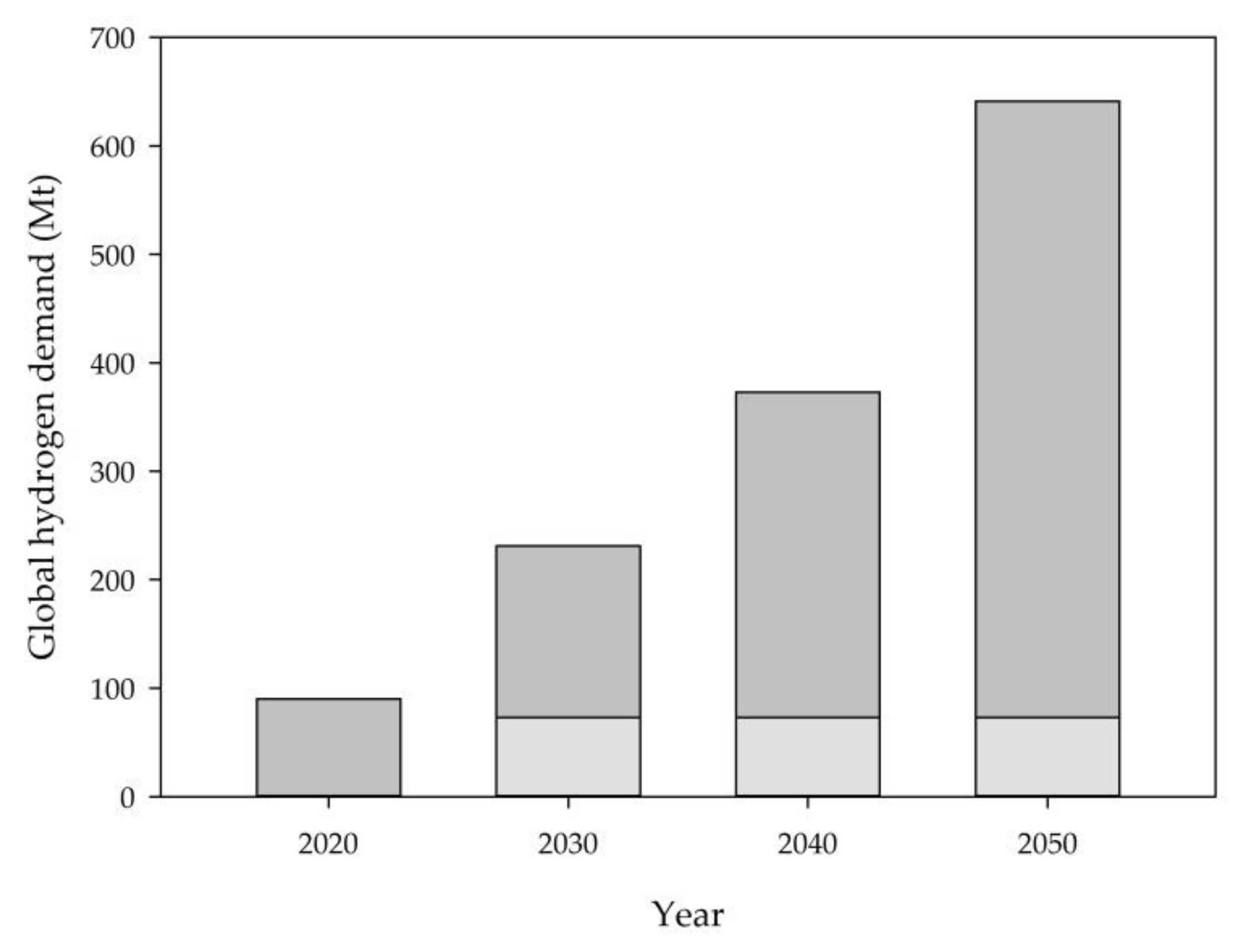
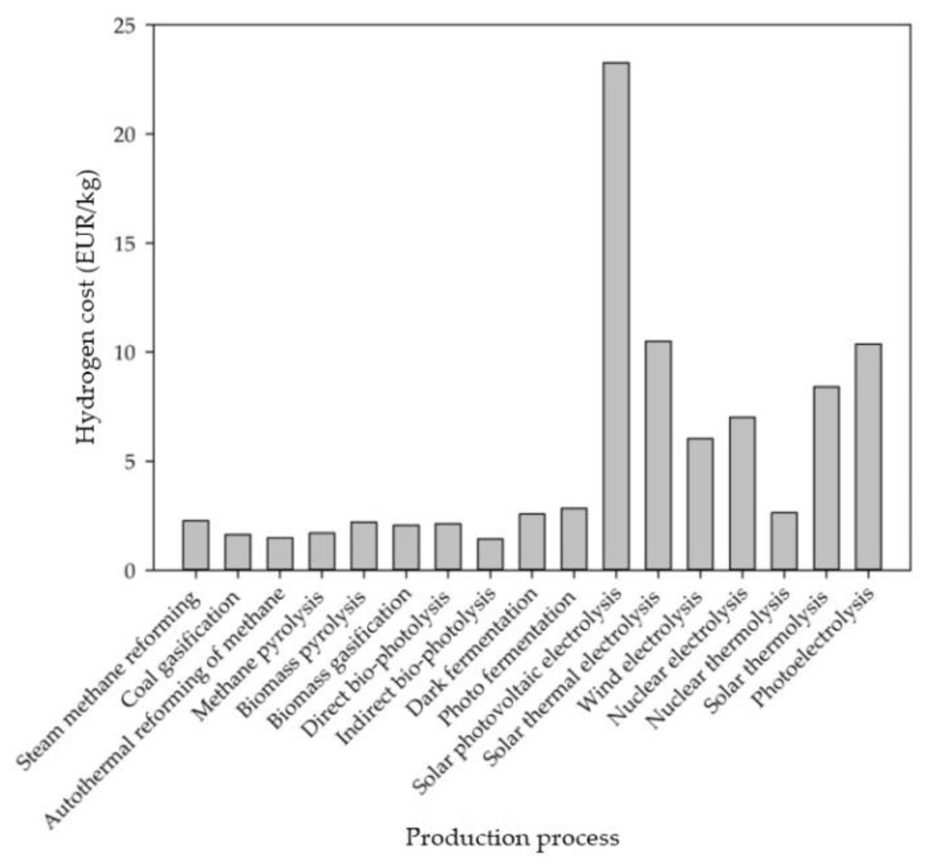
2. Hydrogen Production—A Challenge with Undefined Colors
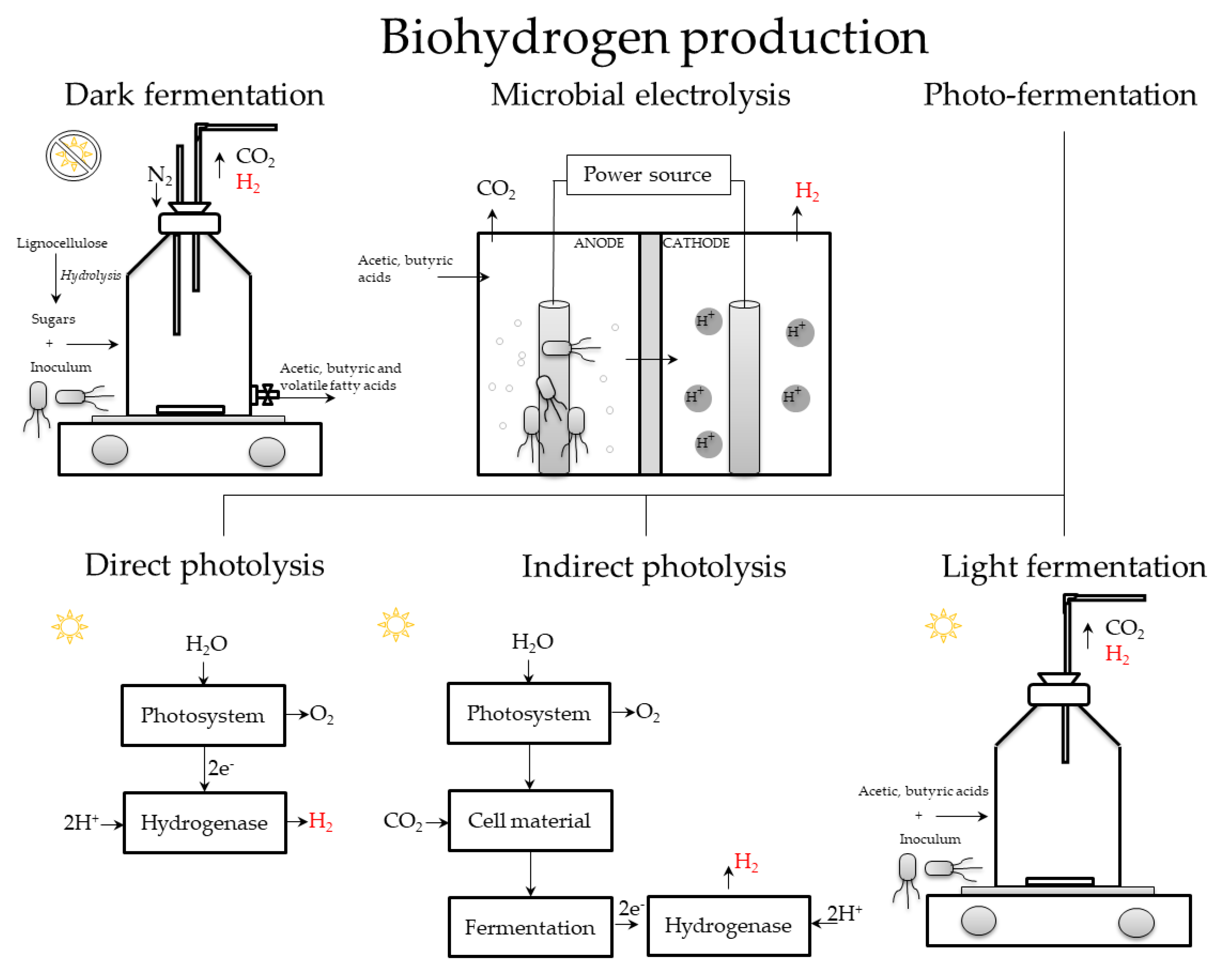
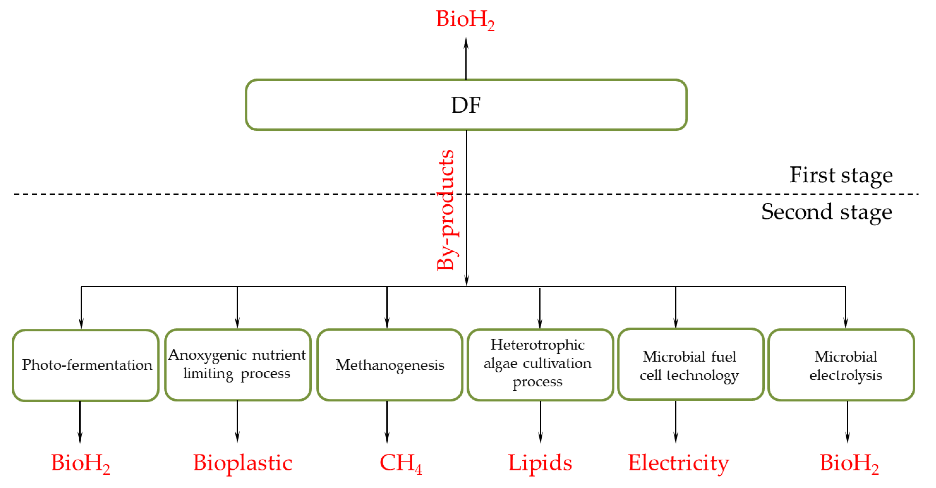
Biohydrogen Production
3. Microfluidic Technology for Enhancing Biohydrogen Production
3.1. Small Size for Large Properties
3.1.1. Cell Cultivation in Microfluidics
3.1.2. Light Irradiation in Microfluidics
3.1.3. Laminar Flow
3.1.4. Integration of Different Processes and Technical Solutions
3.1.5. Numbering Up
3.2. Microfluidic Production of BioH2
4. Obstacles to Be Overcome
4.1. Cell Cultivation
4.2. Modular Systems vs. Integrated Systems
4.3. Sensors
4.4. Microscale CCS
4.5. Selection of the Substrate
4.6. Selection of the Material for the Production of Microdevices
4.7. Changing the User’s Perspective
5. Outlook and Conclusions
Author Contributions
Funding
Data Availability Statement
Conflicts of Interest
References
- United Nations Climate Change. Available online: https://unfccc.int/kyoto_protocol (accessed on 6 July 2022).
- United Nations Climate Change. Available online: https://unfccc.int/process-and-meetings/the-paris-agreement/the-paris-agreement (accessed on 6 July 2022).
- Rathore, D.; Singh, A.; Dahiya, D.; Nigam, P.S. Sustainability of Biohydrogen as Fuel: Present Scenario and Future Perspective. AIMS Energy 2019, 7, 1–19. [Google Scholar] [CrossRef]
- Aruwajoye, G.S.; Kassim, A.; Saha, A.K.; Gueguim Kana, E.B. Prospects for the Improvement of Bioethanol and Biohydrogen Production from Mixed Starch-Based Agricultural Wastes. Energies 2020, 13, 6609. [Google Scholar] [CrossRef]
- Das, S.R.; Basak, N. Molecular Biohydrogen Production by Dark and Photo Fermentation from Wastes Containing Starch: Recent Advancement and Future Perspective. Bioprocess Biosyst. Eng. 2021, 44, 1–25. [Google Scholar] [CrossRef] [PubMed]
- Pereira, C.A.; Coelho, P.M.; Fernandes, J.F.; Gomes, M.H. Study of an Energy Mix for the Production of Hydrogen. Int. J. Hydrogen Energy 2017, 42, 1375–1382. [Google Scholar] [CrossRef]
- Zhang, B.; Zhang, S.X.; Yao, R.; Wua, Y.H.; Qiu, J.S. Progress and Prospects of Hydrogen Production: Opportunities and Challenges. J. Electron. Sci. 2021, 19, 100080. [Google Scholar] [CrossRef]
- Srivastava, R.K.; Shetti, N.P.; Reddy, K.R.; Aminabhavi, T.M. Biofuels, biodiesel and Biohydrogen Production Using Bioprocesses. A Review. Environ Chem. Lett. 2020, 18, 1049–1072. [Google Scholar] [CrossRef]
- Kosourov, S.; Murukesan, G.; Seibert, M.; Allahverdiyeva, Y. Evaluation of Light Energy to H2 Energy Conversion Efficiency in Thin Films of Cyanobacteria and Green Alga Under Photoautotrophic Conditions. Algal. Res. 2017, 28, 253–263. [Google Scholar] [CrossRef]
- Khetkorn, W.; Khanna, N.; Incharoensakdi, A.; Lindblad, P. Metabolic and Genetic Engineering of Cyanobacteria for Enhanced Hydrogen Production. Biofuels 2013, 4, 535–561. [Google Scholar] [CrossRef]
- Tamburic, B.; Dechatiwongse, P.; Zemichael, F.W.; Maitland, G.C.; Hellgardt, K. Process and Reactor Design for Biophotolytic Hydrogen Production. Phys. Chem. Chem. Phys. 2013, 15, 10783–10794. [Google Scholar] [CrossRef]
- Horvath, S.; Fasihi, M.; Breyer, C. Techno-Economic Analysis of a Decarbonized Shipping Sector: Technology Suggestions for A Fleet in 2030 and 2040. Energy Convers. Manag. 2018, 164, 230–241. [Google Scholar] [CrossRef]
- IEA-International Energy Agency. Available online: https://www.iea.org/reports/hydrogen (accessed on 12 July 2022).
- PWC. Available online: https://www.pwc.com/gx/en/industries/energy-utilities-resources/future-energy/green-hydrogen-cost.html (accessed on 12 July 2022).
- Yusaf, T.; Laimon, M.; Alrefae, W.; Kadirgama, K.; Dhahad, H.A.; Ramasamy, D.; Kamarulzaman, M.K.; Yousif, B. Hydrogen Energy Demand Growth Prediction and Assessment (2021–2050) Using a System Thinking and System Dynamics Approach. Appl. Sci. 2022, 12, 781. [Google Scholar] [CrossRef]
- Nnabuife, S.G.; Ugbeh-Johnson, J.; Okeke, N.E.; Ogbonnaya, C. Present and Projected Developments in Hydrogen Production: A Technological Review. Carbon Capture Sci. Technol. 2022, 3, 100042. [Google Scholar] [CrossRef]
- Avargani, V.M.; Zendehboudi, S.; Saady, N.M.C.; Dusseault, M.B. A Comprehensive Review on Hydrogen Production and Utilization in North America: Prospects and Challenges. Energy Convers. Manag. 2022, 269, 115927. [Google Scholar] [CrossRef]
- Hermesmann, M.; Müller, T.E. Green, Turquoise, Blue, or Grey? Environmentally friendly Hydrogen Production in Transforming Energy Systems, Progress in Energy and Combustion. Science 2022, 90, 100996. [Google Scholar] [CrossRef]
- Amin, M.; Hussain Shah, H.; Gul Fareed, A.; Khan, W.U.; Chung, E.; Zia, A.; Ur Rahman Farooqi, Z.; Lee, C. Hydrogen Production Through Renewable and Non-Renewable Energy Processes and Their Impact on Climate Change. Int. J. Hydrogen Energy, 2022; in press. [Google Scholar] [CrossRef]
- Ajanovic, A.; Sayer, M.; Haas, R. The Economics and the Environmental Benignity of Different Colors of Hydrogen. Int. J. Hydrogen Energy 2022, 47, 24136–24154. [Google Scholar] [CrossRef]
- Droege, T. What are the Colors of Hydrogen? Available online: https://www.williams.com/2021/04/23/what-are-the-colors-of-hydrogen/ (accessed on 1 August 2022).
- Dodgshun, J. Hydrogen: Clearing Up the Colours. Available online: https://www.enapter.com/newsroom/hydrogenclearing-up-the-colours (accessed on 1 August 2022).
- Pourali, M.; Abolfazli Esfahani, J. Performance Analysis of a Micro-Scale Integrated Hydrogen Production System by Analytical Approach, Machine Learning, and Response Surface Methodology. Energy 2022, 255, 124553. [Google Scholar] [CrossRef]
- da Silva Veras, T.; Mozer, T.S.; da Costa Rubim Messeder dos Santos, D.; da Silva Cesar, A. Hydrogen: Trends, Production and Characterization of The Main Process Worldwide. Int. J. Hydrogen Energy 2017, 42, 2018–2033. [Google Scholar] [CrossRef]
- Newborough, M.; Cooley, G. Developments in the Global Hydrogen Market: The Spectrum of Hydrogen Colours. Fuel Cells Bull. 2020, 11, 16–22. [Google Scholar] [CrossRef]
- Plevan, M.; Geißler, T.; Abánades, A.; Mehravaran, K.; Rathnam, R.K.; Rubbia, C.; Salmieri, D.; Stoppel, L.; Stückrad, S.; Wetzel, T. Thermal Cracking of Methane in a Liquid Metal Bubble Column Reactor: Experiments and Kinetic Analysis. Int. J. Hydrogen Energy 2015, 40, 8020–8033. [Google Scholar] [CrossRef]
- Geißler, T.; Abánades, A.; Heinzel, A.; Mehravaran, K.; Müller, G.; Rathnam, R.K.; Rubbia, C.; Salmieri, D.; Stoppel, L.; Stückard, S.; et al. Hydrogen Production Via Methane Pyrolysis in a Liquid Metal Bubble Column Reactor with a Packed Bed. Chem. Eng. J. 2016, 299, 192–200. [Google Scholar] [CrossRef]
- Diab, J.; Fulcheri, L.; Hessel, V.; Rohani, V.; Frenklach, M. Why Turquoise Hydrogen Will Be a Game Changer for the Energy Transition. Int. J. Hydrogen Energy 2022, 47, 25831–25848. [Google Scholar] [CrossRef]
- Wappler, M.; Unguder, D.; Lu, X.; Ohlmeyer, H.; Teschke, H.; Lueke, W. Building the Green Hydrogen Market—Current State and Outlook on Green Hydrogen Demand and Electrolyzer Manufacturing. Int. J. Hydrogen Energy 2022, in press. [Google Scholar] [CrossRef]
- Zwickl-Bernhard, S.; Auer, H. Green Hydrogen from Hydropower: A Non-Cooperative Modeling Approach Assessing the Profitability Gap and Future Business Cases. Energy Strategy Rev. 2022, 43, 100912. [Google Scholar] [CrossRef]
- Dawood, F.; Anda, M.; Shafiullah, G.M. Hydrogen Production for Energy: An Overview. Int. J. Hydrogen Energy 2020, 45, 3847e69. [Google Scholar] [CrossRef]
- Schneider, S.; Balor, S.; Graf, F.; Kolb, T. State of the Art of Hydrogen Production Via Pyrolysis of Natural Gas. Chem. Bio. Eng. Reviews 2020, 7, 150e8. [Google Scholar] [CrossRef]
- Nikolaidis, P.; Poullikkas, A. A Comparative Overview of Hydrogen Production Processes. Renew. Sustain. Energy Rev. 2017, 67, 597–611. [Google Scholar] [CrossRef]
- Sarangi, P.K.; Nanda, S. Biohydrogen Production Through Dark Fermentation. Chem. Eng. Technol. 2020, 43, 601–612. [Google Scholar] [CrossRef]
- Sen, B.; Aravind, J.; Lin, C.-Y.; Lay, C.-H.; Hsieh, P.H. Biohydrogen Production Perspectives from Organic Waste with Focus on Asia. In Biorefinery; Springer: Cham, Switzerland, 2019; pp. 413–435. [Google Scholar]
- Balat, M. Production of Hydrogen via Biological Processes. Energy Sources A Recovery Util. Environ. Eff. 2009, 31, 1802–1812. [Google Scholar] [CrossRef]
- Cárdenas, E.L.M.; Zapata-Zapata, A.D.; Kim, D. Hydrogen Production from Coffee Mucilage in Dark Fermentation with Organic Wastes. Energies 2018, 12, 71. [Google Scholar] [CrossRef] [Green Version]
- Priya, S.B.; Raghava Reddy, J.; Venkata Reddy, C.; Shett, I.N.P.; Kulkarni, R.V.; Raghu, R.V. Prospects of Biohydrogen Production from Organic Waste: A Review. Chem. Eng. Technol. 2020, 43, 7. [Google Scholar] [CrossRef]
- Ferraren-De Cagalitan, D.D.T.; Abundo, M.L.S. A Review of Biohydrogen Production Technology for Application Towards Hydrogen Fuel Cells. Renew. Sust. Energ. Rev. 2021, 151, 111413. [Google Scholar] [CrossRef]
- Azwar, M.Y.; Hussain, M.A.; Abdul-Wahab, A.K. Development of Biohydrogen Production by Photobiological, Fermentation and Electrochemical Processes: A Review. Renew. Sustain. Energy. Rev. 2014, 31, 158–173. [Google Scholar] [CrossRef]
- Łukajtis, R.; Hołowacz, I.; Kucharska, K.; Glinka, M.; Rybarczyk, P.; Przyjazny, A.; Kamiński, M. Hydrogen Production from Biomass Using Dark Fermentation. Renew. Sustain. Energy. Rev. 2018, 91, 665–694. [Google Scholar] [CrossRef]
- Ghimire, A.; Frunzo, L.; Pirozzi, F.; Trably, E.; Escudie, R.; Lens, P.N.L.; Esposito, G. A Review on Dark Fermentative Biohydrogen Production from Organic Biomass: Process Parameters and Use of By-Products. Appl. Energy 2015, 144, 73–95. [Google Scholar] [CrossRef]
- Elbeshbishy, E.; Dhar, B.R.; Nakhla, G.; Lee, H.S. A Critical Review on Inhibition of Dark Biohydrogen Fermentation. Renew. Sustain. Energy. Rev. 2017, 79, 656–668. [Google Scholar] [CrossRef]
- Kossalbayev, B.D.; Tomo, T.; Zayadan, B.K.; Sadvakasova, A.K.; Bolatkhan, K.; Alwasel, S.; Allakhverdiev, S.I. Determination of the Potential of Cyanobacterial Strains for Hydrogen Production. Int. J. Hydrogen Energy 2019, 45, 2627–2639. [Google Scholar] [CrossRef]
- Rather, A.H.; Srivastav, A.K. A Study on Biohydrogen Production based on Biophotolysis from Cyanobacteria. Ann. Rom. Soc. Cell Biol. 2021, 25, 12500–12509. [Google Scholar]
- Oncel, S.S.; Kose, A.; Faraloni, C.; Imamoglu, E.; Elibol, M.; Torzillo, G.; Sukan, F.V. Biohydrogen Production Using Mutant Strains of Chlamydomonas Reinhardtii: The Effects of Light Intensity and Illumination Patterns. Biochem. Eng. J. 2014, 92, 47–52. [Google Scholar] [CrossRef]
- Sengmee, D.; Cheirsilp, B.; Suksaroge, T.T.; Prasertsan, P. Biophotolysis-Based Hydrogen and Lipid Production by Oleaginous Microalgae Using Crude Glycerol as Exogenous Carbon Source. Int. J. Hydrogen Energy 2017, 42, 1970–1976. [Google Scholar] [CrossRef]
- Lu, C.; Li, W.; Zhang, Q.; Liu, L.; Zhang, N.; Qu, B.; Yang, X.; Xu, R.; Chen, J.; Sun, Y. Enhancing Photo-Fermentation Biohydrogen Production by Strengthening the Beneficial Metabolic Products with Catalysts. J. Clean. Prod. 2021, 317, 128437. [Google Scholar] [CrossRef]
- Zhang, T.; Jiang, D.; Zhang, H.; Jing, Y.; Tahir, N.; Zhang, Y.; Zhang, Q. Comparative Study on Bio-Hydrogen Production from Corn stover: Photo-Fermentation, Dark-Fermentation and Dark-Photo Co-fermentation. Int. J. Hydrogen Energy 2020, 45, 3807–3814. [Google Scholar] [CrossRef]
- Ji, Y.; Sultan, M.A.; Kim, D.Y.; Meeks, N.; Hastings, J.T.; Bhattacharyya, D. Effect of Silica-Core Gold-Shell Nanoparticles on The Kinetics of Biohydrogen Production and Pollutant Hydrogenation Via Organic Acid Photofermentation Over Enhanced Near-Infrared Illumination. Int. J. Hydrogen Energy 2021, 46, 7821–7835. [Google Scholar] [CrossRef] [PubMed]
- Al-Mohammedawi, H.H.; Znad, H.; Eroglu, E. Improvement of Photofermentative Biohydrogen Production Using Pre-Treated Brewery Wastewater with Banana Peels Waste. Int. J. Hydrogen Energy 2019, 44, 2560–2568. [Google Scholar] [CrossRef]
- Fitri Hanipa, M.A.; Abdul, P.M.; Jahim, J.; Sobri Takriff, M.; Reungsang, A. Valorising Fermentation Effluent Rich in Short-Chain Fatty Acids and Sugars for Biohydrogen Via Photofermentation by Rhodobacter sphaeroides KKU-PS1. IOP Conf. Ser. Earth Environ. Sci. 2019, 268, 012077. [Google Scholar] [CrossRef]
- Hitit, Z.Y.; Lazaro, C.Z.; Hallenbeck, P.C. Single Stage Hydrogen Production from Cellulose Through Photo-Fermentation by A Co-Culture of Cellulomonas fimi and Rhodopseudomonas palustris. Int. J. Hydrogen Energy 2017, 42, 6556–6566. [Google Scholar] [CrossRef]
- Hay, J.X.W.; Wu, T.Y.; Juan, J.C.; Jahim, J.M. Effect of Adding Brewery Wastewater to Pulp and Paper Mill Effluent to Enhance the Photofermentation Process: Wastewater Characteristics, Biohydrogen Production, Overall Performance, and Kinetic Modeling. Environ. Sci. Pollut. Res. 2017, 24, 10354–10363. [Google Scholar] [CrossRef]
- Budiman, P.M.; Wu, T.Y.; Ramanan, R.N.; Jahim, J.M. Reusing Colored Industrial Wastewaters in a Photofermentation for Enhancing Biohydrogen Production by Using Ultrasound Stimulated Rhodobacter sphaeroides. Environ. Sci. Pollut. Res. 2017, 24, 15870–15881. [Google Scholar] [CrossRef]
- Silva, J.; Mendes, J.; Correia, J.; Rocha, M.; Micoli, L. Cashew Apple Bagasse as New Feedstock for the Hydrogen Production Using Dark Fermentation Process. J. Biotechnol. 2018, 286, 71–78. [Google Scholar] [CrossRef]
- Muharja, M.; Junianti, F.; Ranggina, D.; Nurtono, T.; Widjaja, A. An Integrated Green Process: Subcritical Water, Enzymatic Hydrolysis, and Fermentation, for Biohydrogen Production from Coconut Husk. Biores. Technol. 2018, 249, 268–275. [Google Scholar] [CrossRef]
- Lin, R.; Cheng, J.; Ding, L.; Song, W.; Liu, M.; Zhou, J.; Cen, K. Enhanced Dark Hydrogen Fermentation by Addition of Ferric Oxide Nanoparticles Using Enterobacter aerogenes. Biores. Technol. 2016, 207, 213–219. [Google Scholar] [CrossRef]
- Li, Y.; Zhang, Z.; Zhang, Q.; Tahir, N.; Jing, Y.; Xia, C.; Zhu, S.; Zhang, X. Enhancement of Bio-Hydrogen Yield and Ph Stability in Photo Fermentation Process Using Dark Fermentation Effluent as Succedaneum. Biores. Technol. 2019, 297, 122504. [Google Scholar] [CrossRef] [PubMed]
- Ulhiza, T.A.; Puad, N.I.M.; Azmi, A.S. Optimization of Culture Conditions for Biohydrogen Production from Sago Wastewater by Enterobacter Aerogenes Using Response Surface Methodology. Int. J. Hydrogen Energy 2018, 43, 22148–22158. [Google Scholar] [CrossRef]
- Renaudie, M.; Dumas, C.; Vuilleumier, S.; Ernst, B. New Way of Valorization of Raw Coffee Silverskin: Biohydrogen and Acetate Production by Dark Fermentation Without Exogenous Inoculum. Bioresour. Technol. Rep. 2022, 17, 100918. [Google Scholar] [CrossRef]
- Sun, Y.; Ma, Y.; Zhang, B.; Sun, H.; Wang, N.; Wang, L.; Zhang, J.; Xue, R. Comparison of Magnetite/Reduced Graphene Oxide Nanocomposites and Magnetite Nanoparticles on Enhancing Hydrogen Production in Dark Fermentation. Int. J. Hydrogen Energy 2022, 47, 22359–22370. [Google Scholar] [CrossRef]
- Wu, M.; Fu, Q.; Huang, J.; Xu, Q.; Wang, D.; Liu, X.; Yang, J.; Wu, Y.; He, D.; Ni, B.J.; et al. Effect of Sodium Dodecylbenzene Sulfonate on Hydrogen Production from Dark Fermentation of Waste Activated Sludge. Sci. Total Environ. 2021, 799, 149383. [Google Scholar] [CrossRef]
- Sivaramakrishnan, R.; Shanmugam, S.; Sekar, M.; Mathimani, T.; Incharoensakdi, A.; Kim, S.H.; Parthiban, A.; Geo, V.A.; Brindhadevi, K.; Pugazhendhi, A. Insights on Biological Hydrogen Production Routes and Potential Microorganisms for High Hydrogen Yield. Fuel 2021, 291, 120136. [Google Scholar] [CrossRef]
- Ortigueira, J.; Alves, L.; Gouveia, L.; Moura, P. Third Generation Biohydrogen Production by Clostridium Butyricum and Adapted Mixed Cultures from Scenedesmus Obliquus Microalga Biomass. Fuel 2015, 153, 128–134. [Google Scholar] [CrossRef]
- Shanmugam, S.; Sun, C.; Zeng, X.; Wu, Y.R. High-Efficient Production of Biobutanol by a Novel Clostridium Sp. Strain WST With Uncontrolled Ph Strategy. Bioresour. Technol. 2018, 256, 543–547. [Google Scholar] [CrossRef]
- Santiago, S.G.; Trably, E.; Latrille, E.; Buitron, G.; Moreno-Andrade, I. The Hydraulic Retention Time Influences the Abundance of Enterobacter, Clostridium and Lactobacillus During the Hydrogen Production from Food Waste. Lett. Appl. Microbiol. 2019, 69, 138–147. [Google Scholar] [CrossRef]
- Mthethwa, N.P.; Nasr, M.; Kiambi, S.L.; Bux, F.; Kumari, S. Biohydrogen fermentation from Pistia stratiotes (aquatic weed) using mixed and pure bacterial cultures. Int. J. Hydrogen Energy 2019, 44, 17720–17731. [Google Scholar] [CrossRef]
- Turhal, S.; Turanbaev, M.; Argun, H. Hydrogen Production from Melon and Watermelon Mixture by Dark Fermentation. Int. J. Hydrogen Energy 2019, 44, 18811–18817. [Google Scholar] [CrossRef]
- Shanmugam, S.; Krishnaswamy, S.; Chandrababu, R.; Veerabagu, U.; Pugazhendhi, A.; Mathimani, T. Optimal Immobilization of Trichoderma Asperellum Laccase on Polymer Coated Fe3O4@Sio2 Nanoparticles for Enhanced Biohydrogen Production from Delignified Lignocellulosic Biomass. Fuel 2020, 273, 117777. [Google Scholar] [CrossRef]
- Machado, R.G.; Moreira, F.S.; Batista, F.R.X.; Ferreira, J.S.; Cardoso, V.L. Repeated Batch Cycles as an Alternative for Hydrogen Production by Co-Culture Photofermentation. Energy 2018, 153, 861–869. [Google Scholar] [CrossRef]
- Hitit, Z.Y.; Lazaro, C.Z.; Hallenbeck, P.C. Hydrogen Production by Co-Cultures of Clostridium butyricum and Rhodospeudomonas palustris: Optimization of Yield Using Response Surface Methodology. Int. J. Hydrogen Energy 2017, 42, 6578–6589. [Google Scholar] [CrossRef]
- Penniston, J.; Gueguim Kana, E.B. Impact of Medium Ph Regulation on Biohydrogen Production in Dark Fermentation Process Using Suspended and Immobilized Microbial Cells. Biotechnol. Biotechnol. Equip. 2018, 32, 204–212. [Google Scholar] [CrossRef]
- Keskin, T.; Abubackar, H.N.; Arslan, K.; Azbar, N. Biohydrogen Production from Solid Wastes. In Biohydrogen; Elsevier: Amsterdam, The Netherlands, 2019; pp. 321–346. [Google Scholar]
- Mirza, S.S.; Qazi, J.I.; Zhao, Q.; Chen, S. Photo-Biohydrogen Production Potential of Rhodobacter capsulatus-PK from Wheat Straw. Biotechnol. Biofuels. 2013, 6, 2–13. [Google Scholar] [CrossRef]
- Jiang, D.; Ge, X.; Zhang, T.; Liu, H.; Zhang, Q. Photo-Fermentative Hydrogen Production from Enzymatic Hydrolysate of Corn Stalk Pith with A Photosynthetic Consortium. Int. J. Hydrogen Energy 2016, 41, 16778–16785. [Google Scholar] [CrossRef]
- Chen, C.C.; Chuang, Y.S.; Lin, C.Y.; Lay, C.H.; Sen, B. Thermophilic Dark Fermentation of Untreated Rice Straw Using Mixed Cultures for Hydrogen Production. Int. J. Hydrogen Energy 2012, 37, 15540–15546. [Google Scholar] [CrossRef]
- Beig, B.; Riaz, M.; Raza Naqvi, S.; Hassan, M.; Zheng, Z.; Karimi, K.; Pugazhendhi, A.; Atabani, A.; Thuy Lan Chi, N. Current Challenges and Innovative Developments in Pretreatment of Lignocellulosic Residues for Biofuel Production: A Review. Fuel 2021, 287, 119670. [Google Scholar] [CrossRef]
- Gorgec, F.K.; Karapinar, I. Biohydrogen Production from Hydrolyzed Waste Wheat by Dark Fermentation in a Continuously Operated Packed Bed Reactor: The Effect of Hydraulic Retention Time. Int. J. Hydrogen Energy 2019, 44, 136–143. [Google Scholar] [CrossRef]
- Hitit, Z.Y.; Lazaro, C.Z.; Hallenbeck, P.C. Increased Hydrogen Yield and COD Removal from Starch/Glucose Based Medium by Sequential Dark and Photo-Fermentation Using Clostridium butyricum and Rhodopseudomonas palustris. Int. J. Hydrogen Energy 2017, 42, 18832–18843. [Google Scholar] [CrossRef]
- Kuppam, C.; Pandit, S.; Kadier, A.; Dasagrandhi, C.; Velpuri, J. Biohydrogen Production: Integrated Approaches to Improve the Process Efficiency. Microb. Appl. 2017, 1, 189–210. [Google Scholar] [CrossRef]
- Convery, N.; Gadegaard, N. 30 Years of Microfluidics. Micro Nano Eng. 2019, 2, 76–91. [Google Scholar] [CrossRef]
- Bargahi, N.; Ghasemali, S.; Jahandar-Lashaki, S.; Nazari, A. Recent Advances for Cancer Detection and Treatment by Microfluidic Technology Review and Update. Biol. Proced. Online 2022, 24, 5. [Google Scholar] [CrossRef] [PubMed]
- Xie, Y.; Dai, L.; Yang, Y. Microfluidic Technology and Its Application in the Point-of-Care Testing Field. Biosens. Bioelectron. X. 2022, 10, 100109. [Google Scholar] [CrossRef] [PubMed]
- Moradi, E.; Jalili-Firoozinezhad, S.; Solati-Hashjin, M. Microfluidic Organ-on-A-Chip Models of Human Liver Tissue. Acta. Biomater. 2020, 116, 67–83. [Google Scholar] [CrossRef]
- Kolb, G. Review: Microstructured Reactors for Distributed and Renewable Production of Fuels and Electrical Energy. Chem. Eng. Process. 2013, 65, 1–44. [Google Scholar] [CrossRef]
- Soler, L.; Divins, N.J.; Vendrell, X.; Serrano, I.; Llorca, J. Hydrogen Production in Microreactors. In Current Trends and Future Developments on (Bio-) Membranes, New Perspectives on Hydrogen Production, Separation, and Utilization; Elsevier: Amsterdam, The Netherlands, 2020; pp. 141–182. [Google Scholar] [CrossRef]
- Goerke, O.; Pfeifer, P.; Schubert, K. Water Gas Shift Reaction and Selective Oxidation of CO In Microreactors. Appl. Catal. A Gen. 2004, 263, 11–18. [Google Scholar] [CrossRef]
- Im, Y.; Hyung Lee, J.; Sub Kwak, B.; Yeon Do, J.; Kang, M. Effective Hydrogen Production from Propane Steam Reforming Using M/Nio/YSZ Catalysts (M = Ru, Rh, Pd, and Ag). Catal. Today 2018, 203, 168–176. [Google Scholar] [CrossRef]
- Zhu, L.; Kroodsma, N.; Yeom, J.; Haan, J.L.; Shannon, M.A.; Meng, D.D. An on-Demand Microfluidic Hydrogen Generator with Self-Regulated Gas Generation and Self-Circulated Reactant Exchange with a Rechargeable Reservoir. Microfluid. Nanofluid 2011, 11, 569. [Google Scholar] [CrossRef]
- Banerjee, R.; Kumar, S.P.J.; Mehendale, N.; Sevda, S.; Garlapati, V.K. Intervention of Microfluidics in Biofuel and Bioenergy Sectors: Technological Considerations and Future Prospects. Renew. Sust. Energ. Rev. 2019, 101, 548–558. [Google Scholar] [CrossRef]
- Fadakar, A.; Mahdi Mardanpour, M.; Yaghmaei, S. The Coupled Microfluidic Microbial Electrochemical Cell as a Self-Powered Biohydrogen Generator. J. Power Sources 2020, 451, 227817. [Google Scholar] [CrossRef]
- Parkhey, P.; Sahu, R. Microfluidic Microbial Fuel Cells: Recent Advancements and Future Prospects. Int. J. Hydrogen Energy 2021, 46, 3105–3123. [Google Scholar] [CrossRef]
- Goel, S. From Waste to Watts in Micro-Devices: Review on Development of Membraned and Membraneless Microfluidic Microbial Fuel Cell. Appl. Mater. Today 2018, 11, 270e9. [Google Scholar] [CrossRef]
- Mousavi, M.R.; Ghasemi, S.; Sanaee, Z.; Nejad, Z.G.; Mardanpour, M.M.; Yaghmaei, S.; Ghorbanzadeh, M. Improvement of the Microfluidic Microbial Fuel Cell Using a Nickel Nanostructured Electrode and Microchannel Modifications. J. Power Sources 2019, 437, 226891. [Google Scholar] [CrossRef]
- Luo, X.; Xie, W.; Wang, R.; Wu, X.; Yu, L.; Qiao, Y. Fast Start-Up Microfluidic Microbial Fuel Cells with Serpentine Microchannel. Front. Microbiol. 2018, 9, 2816. [Google Scholar] [CrossRef]
- Jiang, H.; Ali, M.A.; Xu, Z.; Halverson, L.J.; Dong, L. Integrated Microfluidic Flow-Through Microbial Fuel Cells. Sci. Rep. 2017, 7, 41208. [Google Scholar] [CrossRef]
- Ma, X.; Huo, Y.X. The Application of Microfludic-Based Technologies in the Cycle of Metabolic Engineering. Synth. Syst. Biotechnol. 2016, 1, 137–142. [Google Scholar] [CrossRef]
- Commenge, J.M.; Falk, L.; Corriou, J.P.; Matlosz, M. Optimal Design for Flow Uniformity in Microchannel Reactors. AIChE J 2002, 48, 345–358. [Google Scholar] [CrossRef]
- Sekoai, P.T.; Awosusi, A.A.; Yoro, K.O.; Singo, M.; Oloye, O.; Ayeni, A.O.; Bodunri, M.; Daramola, M.O. Microbial Cell Immobilization in Biohydrogen Production: A Short Overview. Crit. Rev. Biotechnol. 2018, 38, 157–171. [Google Scholar] [CrossRef]
- Syed, S.M.; Rafeie, M.; Vandamme, D.; Asadnia, M.; Henderson, R.; Taylor, R.A.; Warkiani, M.E. Selective Separation of Microalgae Cells Using Inertial Microfluidics. Bioresour. Technol. 2017, 252, 91–99. [Google Scholar] [CrossRef] [PubMed]
- Ye, D.; Zhang, P.; Li, J.; Zhu, X.; Chen, R.; Liao, Q. In Situ Visualization of Biofilm Formation in a Microchannel for a Microfluidic Microbial Fuel Cell Anode. Int. J. Hydrogen Energy 2020, 46, 14651–14658. [Google Scholar] [CrossRef]
- Subramanian, S.; Huiszoon, R.C.; Chu, S.; Bentley, W.E.; Ghodssi, R. Microsystems for Biofilm Characterization and Sensing—A Review. Biofilm 2020, 2, 100015. [Google Scholar] [CrossRef]
- Kim, H.S.; Devarenne, T.P.; Han, A. A high Throughput Microfuidic Singlecell Screening Platform Capable of Selective Cell Extraction. Lab Chip. 2015, 15, 2467–2475. [Google Scholar] [CrossRef] [PubMed]
- Eu, Y.J.; Park, H.S.; Kim, D.P.; Wook Hong, J. A Microfuidic Perfusion Platform for Cultivation and Screening Study of Motile Microalgal Cells. Biomicrofuidics 2014, 8, 024113. [Google Scholar] [CrossRef] [PubMed]
- Luke, C.S.; Selimkhanov, J.; Baumgart, L.; Cohen, S.E.; Golden, S.S.; Cookson, N.A.; Hasty, J. A Microfuidic Platform for Long-Term Monitoring of Algae in a Dynamic Environment. ACS Synth. Biol. 2016, 5, 8–14. [Google Scholar] [CrossRef]
- Kaminski, T.S.; Garstecki, P. Controlled Droplet Microfuidic Systems for Multistep Chemical and Biological Assays. Chem. Soc. Rev. 2017, 46, 6210–6226. [Google Scholar] [CrossRef]
- Chou, W.L.; Lee, P.Y.; Yang, C.L.; Huang, W.Y.; Lin, Y.S. Recent Advances in Applications of Droplet Microfuidics. Micromachines 2015, 6, 1249–1271. [Google Scholar] [CrossRef]
- Lapierre, F.; Wu, N.; Zhu, Y. Influence of Flow Rate on the Droplet Generation Process in a Microfuidic Chip. In Smart Nano-Micro Materials and Devices; International Society for Optics and Photonics: Melbourne, Australia, 2011; p. 82040H. [Google Scholar]
- Lim, J.; Caen, O.; Vrignon, J.; Konrad, M.; Taly, V.; Baret, J.C. Parallelized Ultrahigh Throughput Microfuidic Emulsifer for Multiplex Kinetic Assays. Biomicrofuidics 2015, 9, 034101. [Google Scholar] [CrossRef] [Green Version]
- Cui, W.; Zhang, M.; Duan, X.; Pang, W.; Zhang, D.; Zhang, H. Dynamics of Electrowetting Droplet Motion in Digital Microfuidics Systems: From Dynamic Saturation to Device Physics. Micromachines 2015, 6, 778–789. [Google Scholar] [CrossRef]
- Au, S.H.; Shih, S.C.C.; Wheeler, A.R. Integrated Microbioreactor for Culture and Analysis of Bacteria, Algae and Yeast. Biomed. Microdevices. 2011, 13, 41–50. [Google Scholar] [CrossRef] [PubMed]
- Cho, S.K.; Moon, H.; Kim, C.J. Creating, Transporting, Cutting, And Merging Liquid Droplets by Electrowetting-Based Actuation for Digital Microfuidic Circuits. J. Microelectromech. Syst. 2003, 12, 70–80. [Google Scholar] [CrossRef]
- Zhao, Y.; Chakrabarty, K. Cross-Contamination Avoidance for Droplet Rout- Ing in Digital Microfuidic Biochips. IEEE Trans Comput Aided Des. Integr Circuits Syst. 2012, 31, 817–830. [Google Scholar] [CrossRef]
- Lin, C.C.Y.; Chang, Y.W. Cross-Contamination Aware Design Methodology for Pin-Constrained Digital Microfuidic Biochips. IEEE Trans Comput Aided Des. Integr Circuits Syst. 2011, 30, 817–828. [Google Scholar] [CrossRef]
- Aghajani Delavar, M.; Wang, J. Numerical Investigation of Ph Control on Dark Fermentation and Hydrogen Production in a Microbioreactor. Fuel 2021, 292, 120355. [Google Scholar] [CrossRef]
- Alias, A.B.; Mishra, S.; Pendharkar, G.; Chen, C.S.; Liu, C.H.; Liu, Y.J.; Yao, D.J. Microfluidic Microalgae System: A Review. Molecules 2022, 27, 1910. [Google Scholar] [CrossRef]
- Yang, Y.T.; Wang, C.Y. Review of Microfluidic Photobioreactor Technology for Metabolic Engineering and Synthetic Biology of Cyanobacteria and Microalgae. Micromachines 2016, 7, 185. [Google Scholar] [CrossRef]
- Kwak, H.S.; Kim, J.Y.H.; Sim, S.J. A Microreactor System for Cultivation of Haematococcus Pluvialis and Astaxanthin Production. J. Nanosci. Nanotechnol. 2015, 15, 1618–1623. [Google Scholar] [CrossRef]
- Perin, G.; Cimetta, E.; Monetti, F.; Morosinotto, T.; Bezzo, F. Novel Micro-Photobioreactor Design and Monitoring Method for Assessing Microalgae Response to Light Intensity. Algal Res. 2016, 19, 69–76. [Google Scholar] [CrossRef]
- Graham, P.J.; Riordon, J.; Sinton, D. Microalgae on Display: A Microfluidic Pixel-Based Irradiance Assay for Photosynthetic Growth. Lab Chip 2015, 15, 3116–3124. [Google Scholar] [CrossRef]
- Velasquez-Orta, S.B.; Curtis, T.P.; Logan, B.E. Energy from Algae Using Microbial Fuel Cells. Biotechnol. Bioeng. 2009, 103, 1068–1076. [Google Scholar] [CrossRef] [PubMed]
- Pinck, S.; Ostormujof, L.M.; Teychené, S.; Erable, B. Microfluidic Microbial Bioelectrochemical Systems: An Integrated Investigation Platform for a More Fundamental Understanding of Electroactive Bacterial Biofilms. Microorganisms 2020, 8, 1841. [Google Scholar] [CrossRef] [PubMed]
- Shirkosh, M.; Hojjat, Y.; Mardanpour, M.M. Boosting Microfluidic Microbial Fuel Cells Performance Via Investigating Electron Transfer Mechanisms, Metal-Based Electrodes, and Magnetic Field Effect. Sci. Rep. 2022, 12, 7417. [Google Scholar] [CrossRef] [PubMed]
- Amador, C.; Gavriilidis, A.; Angeli, P. Flow Distribution in Different Microreactor Scaleout Geometries and the Effect of Manufacturing Tolerances and Channel Blockage Chem. Eng. J. 2004, 101, 379–390. [Google Scholar] [CrossRef]
- Wang, J. Theory of Flow Distribution in Manifolds. Chem. Eng. J. 2011, 168, 1331–1345. [Google Scholar] [CrossRef]
- Wang, J. Theory and Practice of Flow Field Designs for Fuel Cell Scaling-Up: A Critical Review. Appl. Energy. 2015, 157, 640–663. [Google Scholar] [CrossRef]
- Huo, C.; Bai, C.; Zhang, P. Micropumps for Microfluidic Devices and BioMEMS. J. Phys. Conf. Ser. 2020; 1626, 012040. [Google Scholar] [CrossRef]
- Das, P.K.; Hasan, A.B.M.T. Mechanical Micropumps and Their Applications: A Review. AIP Conf. Proc. 2017, 1851, 020110. [Google Scholar] [CrossRef]
- Keçili, R.; Hussain, C.M. Green Micro Total Analysis Systems (Gμtas) For Environmental Samples. Trends Environ. Anal. Chem. 2021, 31, e00128. [Google Scholar] [CrossRef]
- Mardanpour, M.M.; Yaghmaei, S. Dynamical Analysis of Microfluidic Microbial Electrolysis Cell Via Integrated Experimental Investigation and Mathematical Modeling. Electrochim. Acta 2017, 227, 317–329. [Google Scholar] [CrossRef]
- Delavar, M.A.; Wang, J. Three-Dimensional Modeling of Photo Fermentative Biohydrogen Generation in A Microbioreactor. Renew. Energy 2022, 181, 1034–1045. [Google Scholar] [CrossRef]
- Gele, M.Y.; Yaghmaei, S.; Mardanpour, M.M. A Comparative Study of Three Types of Anode Electrodes in A Microfluidic. Iran. J. Hydrog. Fuel Cell 2021, 8, 13–21. [Google Scholar] [CrossRef]
- Chiu, D.T.; deMello, A.J.; Di Carlo, D.; Doyle, P.S.; Hansen, C.; Maceiczyk, R.M.; Wootton, R.C.R. Small but Perfectly Formed? Successes, Challenges, and Opportunities for Microfluidics in the Chemical and Biological Sciences. Chem 2017, 2, 201–223. [Google Scholar] [CrossRef]
- Fernandes, A.C.; Gernaey, K.V.; Krühne, U. Connecting Worlds—A View on Microfluidics for a Wider Application. Biotechnol. Adv. 2018, 36, 1341–1366. [Google Scholar] [CrossRef] [PubMed]
- Halldorsson, S.; Lucumi, E.; Gómez-Sjöberg, R.; Fleming, R.M.T. Advantages and Challenges of Microfluidic Cell Culture in Polydimethylsiloxane Devices. Biosens. Bioelectron. 2015, 63, 218–231. [Google Scholar] [CrossRef]
- Owens, C.E.; Hart, A.J. High-Precision Modular Microfluidics by Micromilling of Interlocking Injection-Molded Blocks. Lab Chip 2018, 18, 890–901. [Google Scholar] [CrossRef]
- Mark, D.; Haeberle, S.; Roth, G.; von Stetten, F.; Zengerle, R. Microfluidic Lab-on-a-Chip Platforms: Requirements, Characteristics and Applications. Chem. Soc. Rev. 2010, 39, 1153–1182. [Google Scholar] [CrossRef]
- Luong, H.M.; Pham, M.T.; Guin, T.; Pokharel Madhogaria, R.; Phan, M.H.; Keefe Larsen, G.; Nguyen, T.H. Sub-Second and Ppm-Level Optical Sensing of Hydrogen Using Templated Control of Nano-Hydride Geometry and Composition. Nat. Commun. 2021, 12, 2414. [Google Scholar] [CrossRef]
- Zhang, Y.; Peng, H.; Qian, X.; Zhang, Y.; An, G.; Zhao, Y. Recent Advancements in Optical Fiber Hydrogen Sensors. Sens. Actuators B Chem. 2017, 244, 393–416. [Google Scholar] [CrossRef] [Green Version]
- Ganapathy, H.; Steinmayer, S.; Shooshtari, A.; Dessiatoun, S.; Alshehhi, M.; Ohadi, M.M. Enhanced Carbon Capture in a Multiport Microscale Absorber. In Proceedings of the ASME 2013 International Mechanical Engineering Congress and Exposition, IMECE2013. San Diego, CA, USA, 15–21 November 2013 ; Volume 56291, p. V06BT07A006. [Google Scholar] [CrossRef]
- Sustainable and Optimal Use of Biomass for Energy in the EU Beyond 2020. European Commission, Directorate General for Energy. 2017. Available online: https://ec.europa.eu/energy/sites/ener/files/documents/biosustain_annexes_final.pdf (accessed on 17 August 2022).
- Xu, S.; Wang, R.; Gasser, T.; Ciais, P.; Peñuelas, J.; Balkanski, Y.; Boucher, O.; Janssens, I.A.; Sardans, J.; Clark, J.H.; et al. Delayed Use of Bioenergy Crops Might Threaten Climate and Food Security. Nature 2022, 609, 299–306. [Google Scholar] [CrossRef]
- Shields, C.W.; Ohiri, K.A.; Szott, L.M.; López, G.P. Translating Microfluidics: Cell Separation Technologies and Their Barriers to Commercialization. Cytom. Part B Clin. Cytom. 2017, 92, 115–125. [Google Scholar] [CrossRef] [Green Version]


| Advantages | Disadvantages |
|---|---|
| produced from various sources | dependence on fossil fuels to drive some processes |
| high energy conversion | investment and overall costs |
| environmentally friendly | storage and transport |
| renewable | highly flammable |
| regeneration | |
| zero carbon emission | |
| reduces carbon footprint | |
| versatility of use |
| Gray | Blue | Turquoise | Green |
|---|---|---|---|
| Hydrogen produced by steam methane reforming or coal gasification using natural gas or coal. | Hydrogen produced by steam methane reforming or gasification with carbon capture and storage using natural gas. | Hydrogen produced by methane pyrolysis from natural gas. | Hydrogen produced by polymer electrolyte membrane water electrolysis using water. |
| GHG footprint: high | GHG footprint: low | GHG footprint: carbon free | GHG footprint: carbon free |
| Process | Substrate | Microorganism | BioH2 Yield | Reference |
|---|---|---|---|---|
| Direct photolysis | Chlorophyll a + b | Synechocystis sp. PCC 6803 | 4.44 μmol H2/mg chlorophyll | [44] |
| Chlorophyll a + b | Desertifilum sp. IPPAS B1220 | 38.014 μmol H2/mg chlorophyll | [44] | |
| Chlorophyll a + b and 10 mM 3-(3,4-dichlorophenyl)-1, 1-dimethylurea | Desertifilum sp. IPPAS B1220 | 57.77 μmol H2/mg chlorophyll | [44] | |
| Indirect photolysis | Crude glycerol | Cyanothece sp. ATCC 51142 | 74.2 mL H2/L glycerol | [45] |
| Starch | Chlamydomonas reinhardtii D240, D239-40, D240-41 | 388–490 mL H2/L starch | [46] | |
| Crude glycerol | Chlorella sp. | 11.65 mL H2/L glycerol | [47] | |
| Photo-fermentation | Corn stalk | Mixed strains (Rhodospirillum rubrum, Rhodopseudomonas capsulata, Rhodopseudomonas palustris, Rhodobacter capsulatus, Rhodobacter sphaeroides) | 160.4 ± 2.7 mL H2/g corn stalk | [48] |
| Corn stover | Photosynthetic bacteria HAU-M1 and dark fermentative bacteria Enterobacter aerogenes | 36.08–141.42 mL H2/g total solids | [49] | |
| Acetate | Rhodopseudomonas palustris CGA009 | 2.31 mol H2/mol acetate | [50] | |
| Brewery wastewater | Rhodobacter sphaeroides 158 DSM | 408.33 mL H2/L wastewater | [51] | |
| Mixed substrate (biosuccinate effluent) | Rhodobacter sphaeroides KKU-PS1 | 1217 mL H2/L biosuccinate | [52] | |
| Cellulose | Cellulomonas fimi ATCC 484 and Rhodopseudomonas palustris GCA009 | 44 mmol H2/L cellulose | [53] | |
| Brewery wastewater and pulp and paper mill effluent | Rhodobacter sphaeroides NCIMB 8253 | 0.69 mol H2/L medium | [54] | |
| Palm oil mill effluent and pulp and paper mill effluent | Rhodobacter sphaeroides NCIMB8253 | 9.98 mol H2/L medium | [55] | |
| Dark fermentation | Cashew apple bagasse | Clostridium roseum ATCC 17797 | 1.89 mL H2/g cashew apple bagasse | [56] |
| Coconut husk | Enterobacter aerogenes NBRC 13534 | 0.279 mol H2/mol reducing sugar | [57] | |
| Potato and glucose | Rhodopseudomonas palustris | 7.35 mmol H2/substrate | [53] | |
| Cassava | Enterobacter aerogenes ATCC 13408 | 124.3 mL H2/substrate | [58] | |
| Corn stew | Sludge | 1287.06 mL H2/g total organic carbon | [59] | |
| Sago wastewater | Enterobacter aerogenes | 7.42 mmol H2/g glucose | [60] | |
| Coffee silverskin | Indigenous microflora | 24.1 mL H2/g COD (chemical oxygen demand) | [61] | |
| Glucose | Mixed culture | 198.3 mg H2/g glucose | [62] | |
| Waste activated sludge | Mixed culture | 10.73 mL H2/g volatile suspended solids | [63] |
| Property | Advantage of Microreactors | |||
|---|---|---|---|---|
| Surface-to-volume (S/V) ratio |
| |||
| Dimensionless numbers |
| |||
| Conventional reactor | Microreactor | Change | ||
| Bond number (ratio of gravitational forces and surface tension) | 3 · 10−2 | 10−3 | Reduced | |
| Eötvös number (similar to the Bond feature; the difference is that the characteristic dimension can be length) | 3 · 10−2 | 10−3 | Reduced | |
| Weber number (ratio of internal force and surface tension force) | 8 · 10−3 | 10−7 | Reduced | |
| Reynolds number (ratio of inertial force and viscous force) | 106 | 1 | Reduced | |
| Capillary number (viscosity to surface ratio tension) | 10−2 | 10−4 | Reduced | |
| Froude number (ratio of inertial and gravitational force) | 2 · 10−1 | 10−4 | Reduced | |
| Ohnesorge number (ratio of viscous force to to the square root of the product of internal and surface forces tension) | 10−5 | 10−2 | Increased | |
| Suratman number (surface tension ratio according to the momentum transfer) | 107 | 103 | Reduced | |
| Diffusion time |
| |||
| Surface tensions |
| |||
Publisher’s Note: MDPI stays neutral with regard to jurisdictional claims in published maps and institutional affiliations. |
© 2022 by the authors. Licensee MDPI, Basel, Switzerland. This article is an open access article distributed under the terms and conditions of the Creative Commons Attribution (CC BY) license (https://creativecommons.org/licenses/by/4.0/).
Share and Cite
Šalić, A.; Zelić, B. A Game Changer: Microfluidic Technology for Enhancing Biohydrogen Production—Small Size for Great Performance. Energies 2022, 15, 7065. https://doi.org/10.3390/en15197065
Šalić A, Zelić B. A Game Changer: Microfluidic Technology for Enhancing Biohydrogen Production—Small Size for Great Performance. Energies. 2022; 15(19):7065. https://doi.org/10.3390/en15197065
Chicago/Turabian StyleŠalić, Anita, and Bruno Zelić. 2022. "A Game Changer: Microfluidic Technology for Enhancing Biohydrogen Production—Small Size for Great Performance" Energies 15, no. 19: 7065. https://doi.org/10.3390/en15197065