
Comparative Study of Thermodynamic Regulation Characteristics in a Dual-Tube Reactor with an External Heat Exchanger
 and
and
Abstract
:1. Introduction
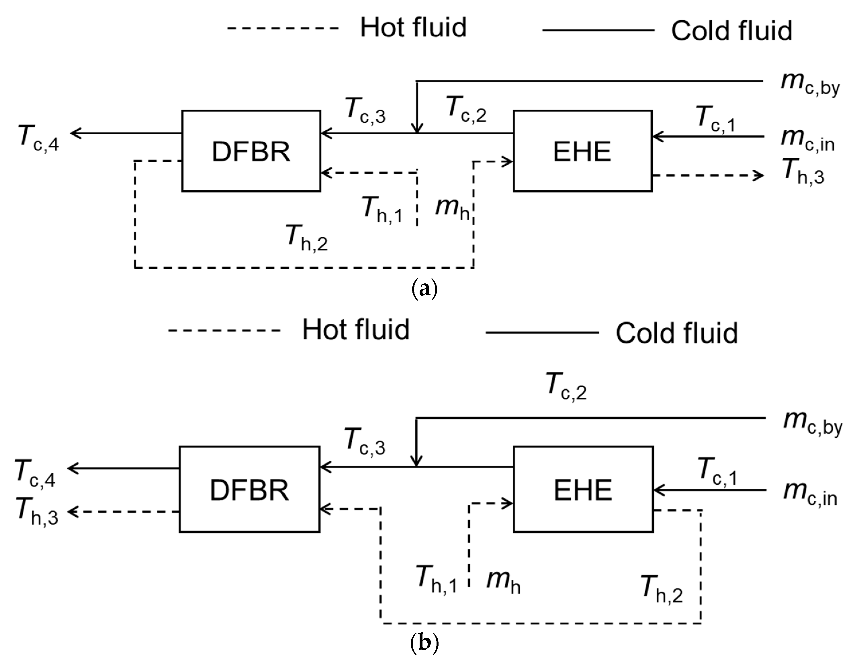
2. Heating Scheme
3. Development of Thermodynamic Equilibrium Model
3.1. Model Establishment
- (1)
- Ignore the effect of gravity on the gas;
- (2)
- The kinetic energy of gas was conserved;
- (3)
- Gas and solid mass were conserved;
- (4)
- Ignore the temperature gradient in the radial direction of the inner tube;
- (5)
- Ignore the effect of temperature on the physical properties of particles and metal containers;
- (6)
- The particle size distribution was uniform and ignore deformation and cracking;
- (7)
- Ignore the effect of radiation heat transfer.
3.2. Algorithm Development
4. Numeral Simulation
4.1. Comparison of the Two Connection Schemes
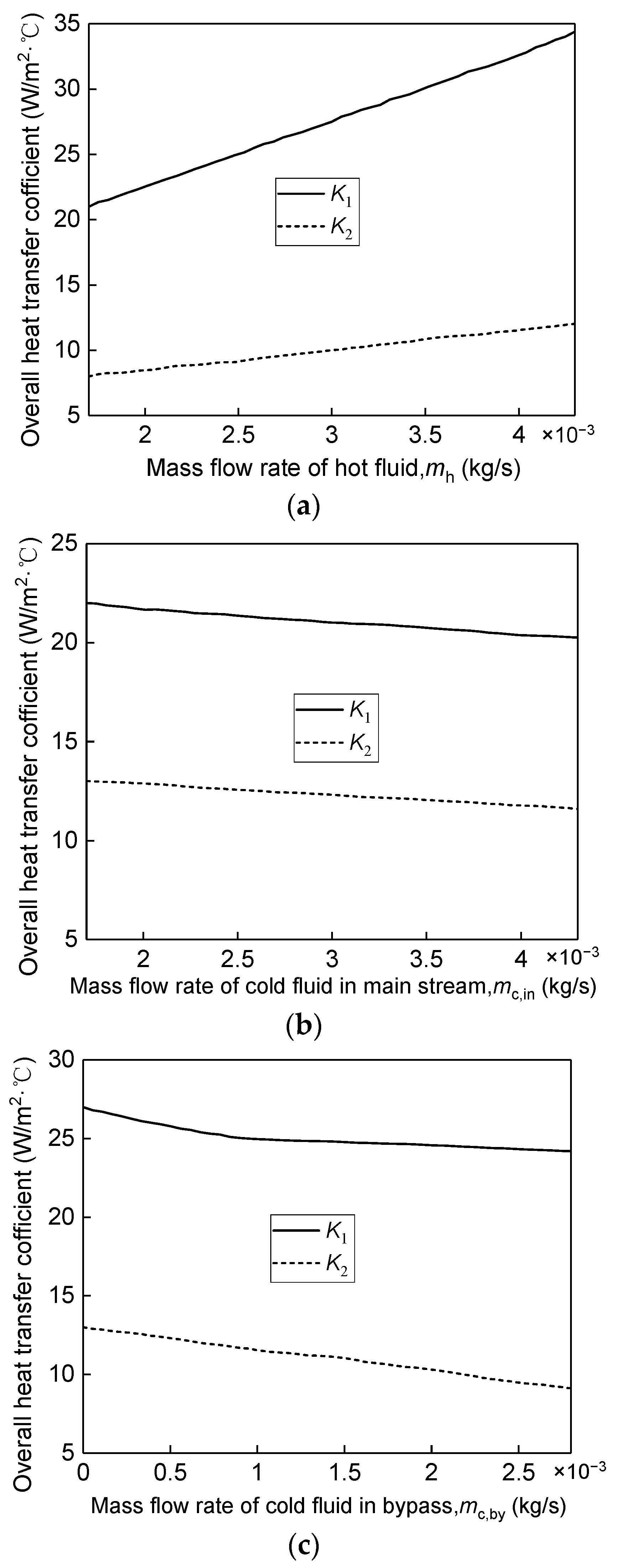
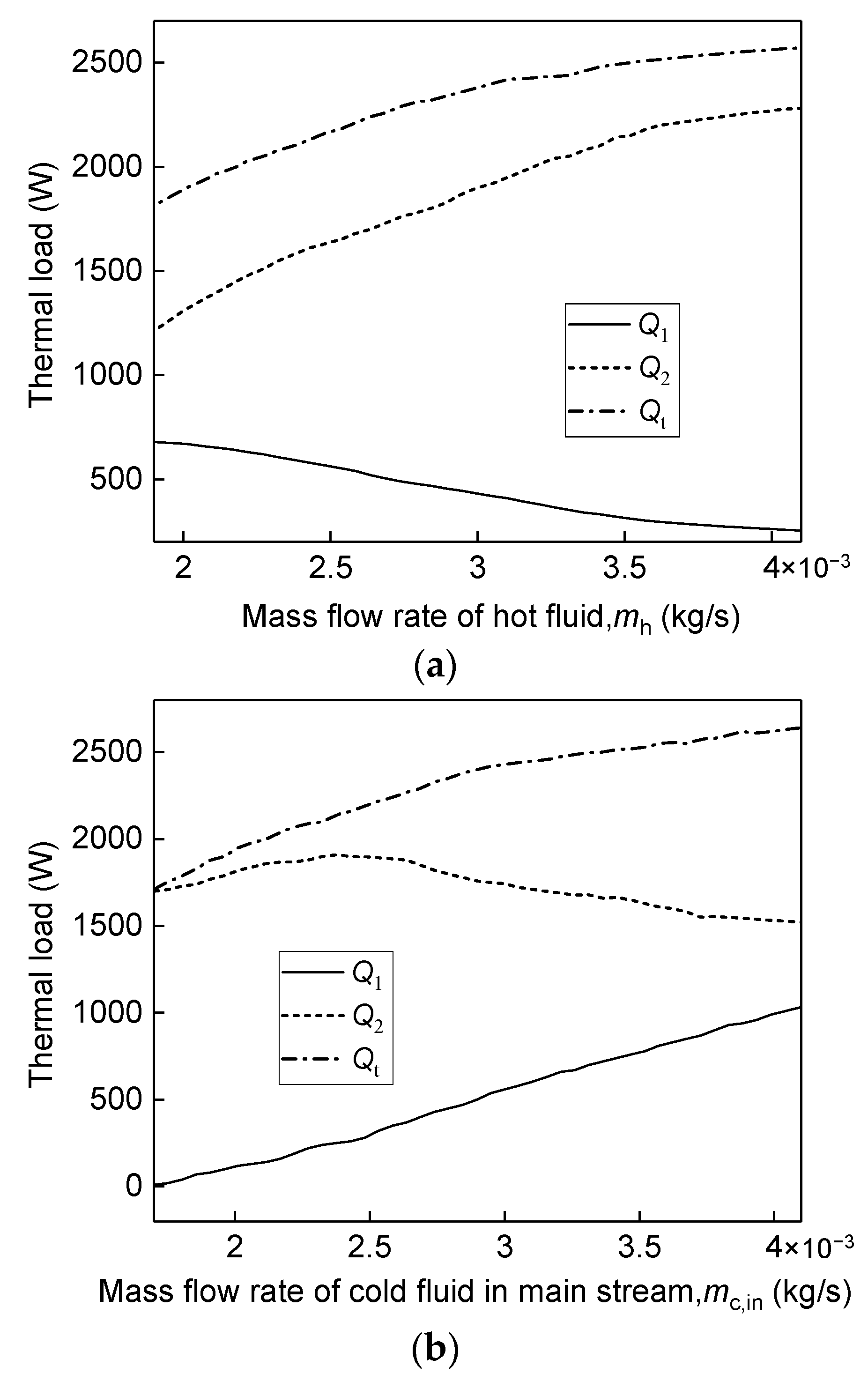
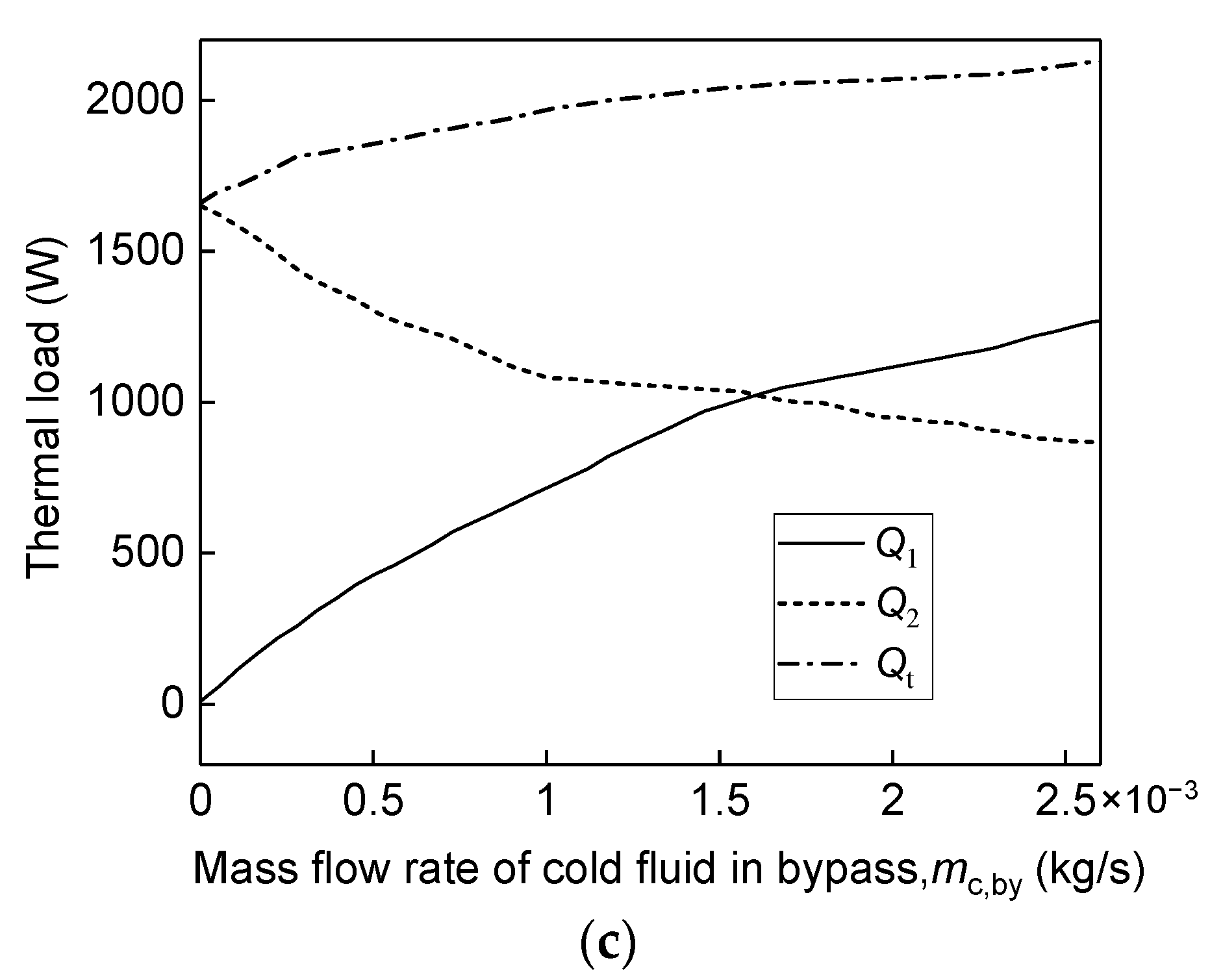
4.2. Thermodynamic Characteristics
4.3. Operating Characteristics
5. Experimental Verification
5.1. Apparatus and Method
5.2. Results and Discussion
6. Conclusions
- (1)
- DFBR was taken as the main body, and the design idea of the tubular reactor system was proposed. EHE was added to improve thermal energy utilization efficiency and a bypass was introduced to achieve precise temperature adjustment, and two connection schemes were proposed.
- (2)
- A thermodynamic equilibrium model of the reactor system was established and a solution algorithm was proposed. The effects of the two connection schemes were compared by numerical simulation and scheme 1 had higher thermal energy utilization efficiency. In addition, the thermal loads of scheme 1 were more sensitive to the cold fluid flow rate in the bypass, which had a larger adjustment range and was suitable for DFBR and EHE.
- (3)
- The basic thermodynamic and operating characteristics of the optimal scheme were carried out by numerical simulation further. The existence of the fluidized bed promoted convective heat transfer with a higher overall heat transfer coefficient of DFBR. Compared with increasing the fluid mass flow rate, increasing the inlet temperature can more effectively increase the adjustment range of temperature in the reaction zone inside.
- (4)
- The experimental verification was carried out and the results showed that the calculated values obtained by the developed model were in good agreement with the experimental values, and the calculation deviation decreased with the decrease in temperature.
Author Contributions
Funding
Institutional Review Board Statement
Informed Consent Statement
Data Availability Statement
Acknowledgments
Conflicts of Interest
Nomenclature
| Acronyms | |
| DTBR | dual fluidized bed reactor |
| EHE | external heat exchanger |
| Symbols | |
| A1 | effective surface area of heat transfer in DFBR, m2 |
| A2 | effective surface area of heat transfer in EHE, m2 |
| Cpc | specific heat capacity, J/(kg °C) |
| d1 | diameter of the inner tube in DFBR, mm |
| d2 | radius of the outer tube in DFBR, mm |
| de | hydraulic diameter of tube section, m |
| i | grid unit number, − |
| K1 | overall heat transfer coefficient in DFBR, W/(m2· °C) |
| K2 | overall heat transfer coefficient in EHE, W/(m2· °C) |
| l | tube length, m |
| mh | mass flow rate of the hot fluid, kg/s |
| mc,in | mass flow rate of the cold fluid in the main stream, kg/s |
| mc,by | mass flow rate of the cold fluid in the bypass, kg/s |
| n | total number of grids, − |
| Q1 | amount of the thermal energy in DFBR, W |
| Q2 | amount of the thermal energy in EHE, W |
| Qt | amount of the thermal energy in the whole system, W |
| T | temperature, °C |
| tm1 | logarithmic mean temperature in DFBR, °C |
| tm2 | logarithmic mean temperature in EHE, °C |
| tm1i | logarithmic mean temperature of the i-th grid in DFBR, °C |
| vc,h | velocity of the hot fluid, m/s |
| vc,in | velocity of the cold fluid in the main stream, m/s |
| vc,by | velocity of the cold fluid in the bypass, m/s |
| ΔA1 | effective heat transfer area of a single grid, W |
| ΔQ1i | amount of the thermal energy of the i-th grid in DFBR, W |
| Greek Letters | |
| α | heat transfer coefficient in EHE, W/(m2·°C) |
| αgs1 | heat transfer coefficient between fluid and solid in the inner tube of DFBR, W/(m2·°C) |
| αgs2 | heat transfer coefficient between fluid and solid in the outer tube of DFBR, W/(m2·°C) |
| αsw1 | heat transfer coefficient between the vessel and solid in the inner tube of DFBR, W/(m2·°C) |
| αsw2 | heat transfer coefficient between the vessel and solid in the outer tube of DFBR, W/(m2·°C) |
| δ1 | thickness of inner tube in DFBR, m |
| δ2 | thickness of spiral plate wall, m |
| λ1 | thermal conductivity of DFBR, W·(m·°C) |
| λ2 | thermal conductivity of EHE, W·(m·°C) |
| Subscripts | |
| c | cold fluid |
| h | hot fluid |
| x | cold fluid or hot fluid |
| out | gas outlet parameters |
| s | solid |
| w | the vessel wall |
References
- Otarod, M.; Supkowski, R.M. Low Reynolds number isotope transient kinetic modeling in isothermal differential tubular catalytic reactors. AICHE J. 2018, 64, 1317–1329. [Google Scholar] [CrossRef]
- Major-Godlewska, M.; Radecki, D. Experimental analysis of gas hold-up for gas-liquid system agitated in a vessel equipped with two impellers and vertical tubular baffles. Pol. J. Chem. Technol. 2018, 20, 7–12. [Google Scholar] [CrossRef]
- Alipour-Dehkordi, A.; Khademi, M.H. Use of a micro-porous membrane multi-tubular fixed-bed reactor for tri-reforming of methane to syngas: CO2, H2O or O2 side-feeding. Int. J. Hydrogen Energy 2019, 44, 32066–32079. [Google Scholar] [CrossRef]
- Petunin, A.B.; Sharapaev, A.I.; Muradova, A.G. Tubular Metal Membranes for Cleaning the Primary-Circuit Coolant of a Pressurized Water Reactor (WWER). Petrol. Chem. 2017, 57, 536–541. [Google Scholar] [CrossRef]
- Wang, X.G.; Tian, B.H.; Wang, C.H.; Wu, J.H. Mathematical modelling of residence time distribution in tubular loop reactors. Can. J. Chem. Eng. 2017, 95, 1101–1108. [Google Scholar] [CrossRef]
- Yang, W.J.; Hong, M.H.; Choi, K.Y. Mathematical modeling and analysis of an interfacial polycarbonate polymerization in a continuous multizone tubular reactor. Polym. Eng. Sci. 2018, 58, 438–446. [Google Scholar] [CrossRef]
- Li, Y.H.; Hong, J.R. Performance assessment of catalytic combustion-driven thermophotovoltaic platinum tubular reactor. Appl. Energy 2018, 211, 843–853. [Google Scholar] [CrossRef]
- Beniich, N.; El Bouhtouri, A.; Dochain, D. Constrained global adaptive controller for a plug-flow tubular reactor with partial temperature measurements. Ima. J. Math. Control Inf. 2019, 36, 1089–1104. [Google Scholar] [CrossRef]
- Liu, K.F.; Zhao, J.; Zhu, D.; Meng, F.; Kong, F.H.; Tang, Y.C. Oxidative coupling of methane in solid oxide fuel cell tubular membrane reactor with high ethylene yield. Catal. Commun. 2017, 96, 23–27. [Google Scholar] [CrossRef]
- Mottaghi, M.; Kuhn, S. Numerical investigation of well-structured porous media in a milli-scale tubular reactor. Chem. Eng. Sci. 2019, 208, 115146. [Google Scholar] [CrossRef]
- Diaz, J.P.; Inostroza, C.; Fernandez, F.G.A. Fibonacci-type tubular photobioreactor for the production of microalgae. Process Biochem. 2019, 86, 1–8. [Google Scholar] [CrossRef]
- Xu, J.W.; Li, J.; Ding, Y.D.; Fu, Q.; Cheng, M.; Liao, Q. Numerical simulation of the flow and heat-transfer characteristics of an aligned external three-dimensional rectangular-finned tube bank. Appl. Therm. Eng. 2018, 145, 110–122. [Google Scholar] [CrossRef]
- Wang, Q.H.; Luo, Z.Y.; Fang, M.X.; Ni, M.J.; Cen, K.F. Development of a new external heat exchanger for a circulating fluidized bed boiler. Chem. Eng. Process. Process Intensif. 2003, 42, 317–335. [Google Scholar] [CrossRef]
- Tian, Z.; Gu, B. Analyses of an integrated thermal management system for electric vehicles. Int. J. Energ. Res. 2019, 43, 5788–5802. [Google Scholar] [CrossRef]
- Zhuang, Y.; Liu, L.L.; Zhang, L.; Du, J. Upgraded Graphical Method for the Synthesis of Direct Work Exchanger Networks. Ind. Eng. Chem. Res. 2017, 56, 14304–14315. [Google Scholar] [CrossRef]
- Luyben, W.L. Heat-Exchanger Bypass Control. Ind. Eng. Chem. Res. 2011, 50, 965–973. [Google Scholar] [CrossRef]
- Cheng, M.; Li, Y.; Li, Z.S.; Cai, N.S. An integrated fuel reactor coupled with an annular carbon stripper for coal-fired chemical looping combustion. Powder Technol. 2017, 320, 519–529. [Google Scholar] [CrossRef]
- Li, X.Y.; Tian, H.; Shu, G.Q.; Hu, C.; Sun, R.; Li, L.G. Effects of external perturbations on dynamic performance of carbon dioxide transcritical power cycles for truck engine waste heat recovery. Energy 2018, 163, 920–931. [Google Scholar] [CrossRef]
- Isaza, P.A.; O’Brien, A.; Warnica, W.D.; Bussmann, M. Assessing axial heat conduction in moving bed heat exchangers. Int. J. Therm. Sci. 2017, 320, 303–313. [Google Scholar] [CrossRef]
- Abdulateef, A.M.; Mat, S.; Sopian, K.; Abdulateef, J.; Gitan, A.A. Experimental and computational study of melting phase-change material in a triplex tube heat exchanger with longitudinal/triangular fins. Sol. Energy 2017, 320, 519–529. [Google Scholar] [CrossRef]
- Zi, Z.W. Petrochemical Design Manual; Chemical Industry Press: Beijing, China, 2015. (In Chinese) [Google Scholar]
- Wu, R.L.; Grace, J.R.; Lim, C.J. A model for heat transfer in circulating fluidized beds. Chem. Eng. Sci. 1990, 45, 3389–3398. [Google Scholar] [CrossRef]
- Bai, Y.; Wang, X.; Si, H. Steady-state simulation of internal heat-transfer characteristics in a double tube reactor. Chem. Eng. Process. Process Intensif. 2019, 144, 107642. [Google Scholar] [CrossRef]
- Wang, X.; Si, H. Novel concept of fluidized bed reactor design for highly efficient internal heat transfer. Ind. Eng. Chem. Res. 2016, 55, 9276–9283. [Google Scholar] [CrossRef]
- Bai, Y.; Liu, D.C.; Si, H. A three-stage heating system of dual-fuel controlled by negative feedback for fluidized bed fast pyrolysis. Sustain. Energy Technol. Assess. 2021, 46, 101228. [Google Scholar] [CrossRef]


| Parameter | Value |
|---|---|
| Inner tube diameter | 180 mm o.d., 170 mm i.d. |
| Outer tube diameter | 273 mm o.d., 263 mm i.d. |
| Inner pipe length | 1.4 m |
| Outer pipe length | 1.55 m |
| Pipes material | 310S |
| Others material | 304 |
| Packing type | quartz sand |
| Quartz sand particles specification | 0.256 mm |
| Quartz sand material | SiO2 |
| Parameter | Value |
|---|---|
| Board thickness | 0.4 m |
| Board width | 0.003 m |
| Actual heat transfer area | 1.7 m2 |
| Inter-channel spacing | 0.02 m |
| Center circle diameter | 0.1 m |
| Maximum outer diameter | 0.658 m |
| Material | 310S |
| Temperature, °C | Density, (kg/m3) | Specific Heat Capacity, kJ/(kg·°C) | Conductivity, W/(m·°C) |
|---|---|---|---|
| 300 | 0.755 | 2.15 | 0.0556 |
| 700 | 0.566 | 2.26 | 0.0683 |
| 1000 | 0.443 | 2.31 | 0.0807 |
| Temperature, °C | Density, (kg/m3) | Specific Heat Capacity, kJ/(kg·°C) | Conductivity, W/(m·°C) |
|---|---|---|---|
| 20 | 1.205 | 1.00 | 0.0259 |
| 350 | 0.566 | 1.06 | 0.0419 |
| 1000 | 0.277 | 1.18 | 0.0807 |
Publisher’s Note: MDPI stays neutral with regard to jurisdictional claims in published maps and institutional affiliations. |
© 2022 by the authors. Licensee MDPI, Basel, Switzerland. This article is an open access article distributed under the terms and conditions of the Creative Commons Attribution (CC BY) license (https://creativecommons.org/licenses/by/4.0/).
Share and Cite
Bai, Y.; Ma, Y.; Ke, C.; Cheng, W.; Guo, G.; Zhao, P.; Cao, C.; Liao, L.; Yang, X.; Fan, Z. Comparative Study of Thermodynamic Regulation Characteristics in a Dual-Tube Reactor with an External Heat Exchanger. Energies 2022, 15, 6794. https://doi.org/10.3390/en15186794
Bai Y, Ma Y, Ke C, Cheng W, Guo G, Zhao P, Cao C, Liao L, Yang X, Fan Z. Comparative Study of Thermodynamic Regulation Characteristics in a Dual-Tube Reactor with an External Heat Exchanger. Energies. 2022; 15(18):6794. https://doi.org/10.3390/en15186794
Chicago/Turabian StyleBai, Yong, Yunfeng Ma, Changjun Ke, Wang Cheng, Guangyan Guo, Peng Zhao, Can Cao, Lifen Liao, Xuebo Yang, and Zhongwei Fan. 2022. "Comparative Study of Thermodynamic Regulation Characteristics in a Dual-Tube Reactor with an External Heat Exchanger" Energies 15, no. 18: 6794. https://doi.org/10.3390/en15186794