Article

The Design and Optimization of Ground-Side Coils for Dynamic Wireless Power Transfer Considering Coupling Variations

National Engineering Laboratory for Electric Vehicles, Beijing Institute of Technology, Beijing 100081, China
*
Author to whom correspondence should be addressed.
Energies 2022, 15(16), 6075; https://doi.org/10.3390/en15166075
Submission received: 11 July 2022 / Revised: 10 August 2022 / Accepted: 10 August 2022 / Published: 22 August 2022

Abstract

:
Dynamic wireless power transfer (DWPT) has attracted widespread attention for its charging flexibility; short-segmented DWPT systems are more suitable for EV charging scenarios because of their higher charging efficiency and lower electromagnetic radiation, compared to long-track DWPT systems. For short-segmented DWPT systems, the structural design of the ground-side coil affects the coupling characteristics of the system, while simultaneously the electric vehicle driving speed and coil arrangement also cause coupling variations, and this will inevitably have an impact on the system’s performance. Therefore, this paper demonstrates the coupler design of a short-segmented system for electric vehicles, focusing on the optimization of ground-side coil. The coupling variations causing by driving speed of EV and coil arrangement are taken into account. Considering the tradeoffs and restrictions, a multi-objective optimization process of coils in DWPT systems is proposed based on the Pareto optimizing method, with three objectives: transfer power, high efficiency and low cost. A reasonable optimal solution is selected from the Pareto front to verify the optimizing method through a constructed prototype.

1. Introduction

As an emerging technique for flexible charging, DWPT has attracted the attention of the automobile industries. DWPT systems can transfer energy during vehicle driving, which can significantly reduce the on-board battery capacity, alleviating anxiety about the mileage problem, and greatly improving the convenience of charging [1]. Currently, DWPT systems can be divided into long-track coils and short-segmented coils, depending on the coil length. Due to the activation of longer transmitter coils, long-track coils can obtain stable coupling coefficients, but they suffer from lower efficiency and serious magnetic leakage problems. In contrast, the short-segmented guideway only needs to activate a specific range of coils, and, thereby, the loss of the transmitter coil is smaller, and the magnetic leakage is improved [2].
Presently, the optimized orientation of the short segmentation system is mainly concentrated on transmission power, transmission efficiency and construction cost. In [3,4,5], single-objective optimization is carried out for efficiency, power and anti-misalignment characteristics, respectively. Ref. [3] proposes a DEU-WPT-based dual excitation unit system; by switching the operating mode when the vehicle is driven, the system energy transfer power can be effectively increased. The author of [4] achieves the maximum efficiency in tracking through adjusting the input voltage of the transmitter side. Ref. [5] proposes a single optimization method for transmit-side coil length design considering the effect of coil distribution on transmission efficiency. In general, many of the previous studies have explored and optimized the individual characteristics of the system, whereas in dynamic wireless charging systems, power, efficiency and cost are often interrelated.
In order to find the optimal solution satisfying multiple design objectives, Pareto theory has been proposed, which can visually represent the relationship between multiple objectives, and thus be used for the evaluation and optimization of the design. Ref. [6] conducts an analysis for couplers of different shapes and uses a multi-objective optimization approach to find the optimal solution, considering mass power density, volume power density and efficiency, by adopting a Pareto theory. Similarly, the author of [7] integrated mass power density, efficiency and cost for a multi-objective optimization analysis with a detailed optimization of the coil structure and ferrite arrangement, and selected the solution set on the Pareto front for verification. In the above work, it is assumed that the transmission power is fixed when designing the coil and its arrangement, ignoring the effect of varying coupling on the transmission power. Furthermore, Ref. [8] incorporates the coupling fluctuation into the multi-objective design of the coupler, and points out that the effect of coupling coefficient versus maximum stray leakage flux density. Additionally, Ref. [9] takes into account the effect of coupled fluctuations on the system efficiency, and carries out a multi-directional trade-off for aligned efficiency, misaligned efficiency and gravimetric power density. However, while the above articles mentioned the effect of coupled fluctuation on efficiency or leakage flux, they do not incorporate the power fluctuations caused by coupled fluctuations into the design. In short-segmented DWPT system, it is necessary to take the effect of coupled fluctuations on the output into consideration.
In general, the resistance to coupling fluctuation of the system can be improved by designing the coupler, compensation network, and DC-DC separately. By analyzing the mutual induction mechanism and designing a complex coupler, the mutual inductance can still remain stable under misalignment [10,11]. Besides, through the analysis of the influence of the compensation element upon the system output, thereby adjusting the resonance relationship between the compensation elements, an optimal design of the compensated network can also enable the output power of the system to resist misalignment [12,13]. Moreover, the anti-misalignment capability of the system can also be enhanced by adjusting the duty ratio of the DC-DC of the pre-stage or post-stage [14,15]. Large fluctuations in power output can be avoided through the above design. However, for short-segmented DWPT systems, changes in coupling are inevitable. Therefore, some scholars have considered the effect of coupling fluctuation for DWPT systems. The effect of track length variation on coupling coefficient fluctuation at different vehicle speeds was investigated in [16], and two optimal segmented track lengths and their coupling coefficients were proposed for slow vehicle speeds or all vehicle speeds. In addition, a decentralized energy picking up coil and the unified circuit model was proposed, by dispersing the secondary coils on both sides of the vehicle body; the power fluctuation of the segmented system at the border of the ground coils can be effectively reduced [17]. However, not only the structure of the coil, but also the driving offset and speed of the vehicle will affect the overall performance of the system.
Neglecting the coupling variation leads to inaccuracy of the system power calculation, resulting in insufficient power transmission. In order to make the calculated transmission power of the system compatible with the actual transmission power, the effect of coupling variation on energy transmission must be taken into consideration.
Therefore, this paper aims to consider the coupling variation in the design process of DWPT system, so as to design the coil structure and arrangement to achieve a comprehensive trade-off of transfer power, transfer efficiency and cost. In this paper, the LCC-LCC topology is adopted, which is widely used for vehicle wireless charging. Its constant current output characteristics and constant transmitter coil current are more suitable for power transfer in the case of coupling variations. In Section 2, the structure of the segmented system and the circuit parameter relationships are presented. Moreover, the transient transfer power is introduced to characterize the power variation under different couplings, and the average transfer power is brought in to represent the average energy transfer capability of the system. Furthermore, the loss distribution of each component was also analyzed to characterize the efficiency of the overall transmission process. The multi-objective optimization process of the coil is proposed, and the optimization results are given and discussed in Section 3. The experimental results of the prototype are given in Section 4 and the key conclusions are given in Section 5.

2. System Description and Power Analysis

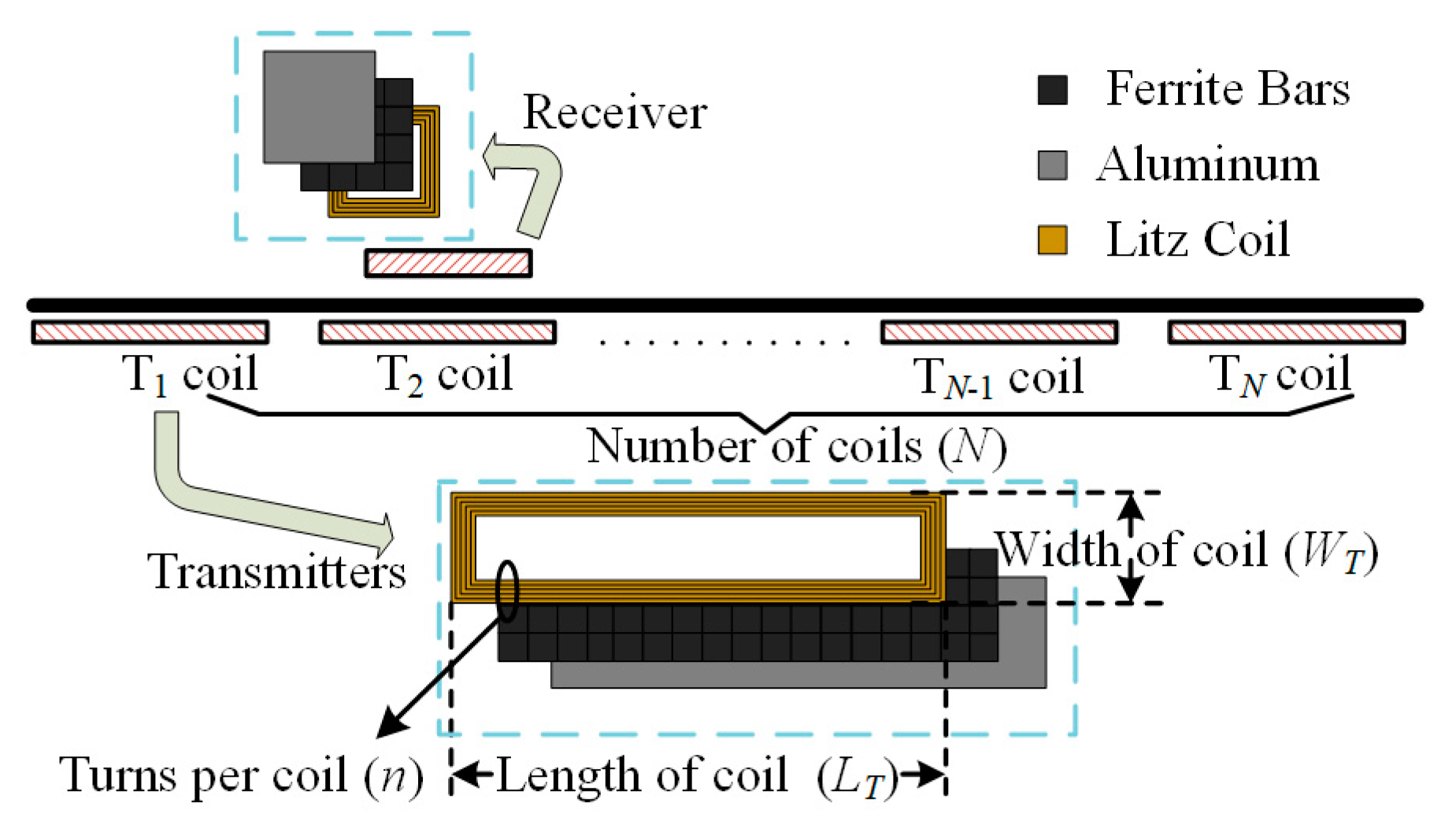
2.1. System Description and Circuit Parameters

The short segmented DWPT system is composed of ground-side elements and vehicle-side elements, as drawn in Figure 1. As for the ground-side, the components include an inverter, capacitive and inductive compensation components, and a ground-side transmission coil; similarly, the vehicle-side includes a vehicle-side coil, capacitive and inductive compensation components and a rectifier. The high frequency current is generated by the inverter and injected into the ground-side coil, thus generating an induced magnetic field between the couplers. Then, the vehicle-side coil generates an induced voltage, which flows through the rectifier bridge and is injected into the vehicle’s battery. Multiple ground-side coils are usually supplied with high frequency power from the same inverter. As shown in Figure 1, when a vehicle passes a certain coil, the corresponding switch is closed, which means that coil is excited, while the switches of the remaining coils keep open. This drive method can save the construction cost of the system on the one hand, and on the other hand, it can improve the energy transfer efficiency and reduce electromagnetic radiation by using time-sharing activation for each switch.
In the LCC-LCC topology, there is no current surge in the resonant cavity under the coupling offset, which helps to ensure the reliability of the system, and the constant current output characteristics of the whole system can therefore be guaranteed. In order to simplify circuit analysis, the fundamental harmonic approximation (FHA) method and mutual-inductance model-based circuit is depicted in Figure 2. M is the mutual inductance between the transmitter and receiver coils and k represent the coupling coefficient defined as k = M / L 1 L 2 . UAB and Uab refer to the equivalent AC voltage. The resonant frequency of the compensation circuits on both sides are the same and are equal to the output frequency of the inverter, as shown below:
ω 0 = 1 / L f 1 C f 1 = 1 / ( L 1 L f 1 ) C 1 = 1 / L f 2 C f 2 = 1 / ( L 2 L f 2 ) C 2
By writing the Kirchhoff voltage equation for the circuit and substituting the resonance conditions above, the output power of the system can be obtained as follows [18]:
P o u t = k L 1 L 2 U A B U a b j ω 0 L f 1 L f 2
It can be seen that the transmission power of the system is closely related to the coupling state. In a short segmented DWPT system, the coupling coefficient fluctuates all the time, which means that the power fluctuates during transmission. Besides, this equation is only applicable when the system works in continuous conduction mode (CCM). Additionally, as the coupling state changes, the system may change to discontinuous conduction mode (DCM), causing the actual transmitted power to deviate from the transmitted power of the ideal model.

2.2. Single-Point Power and Average Power

The calculation of CCM and DCM involving coil resistance is usually solved by the system state equation proposed by Li [19]. By combining the system parameters and writing a system of time domain equations, the time domain expression for the current on each component over a period can be derived. Therefore, the output power of the system in a single switching cycle can be expressed as
P ( x ) = V a b T 0 T a b s ( i L f 2 ( t ) ) d t
where abs represent the absolute value, and T is the switching period, Vout is the battery voltage and P(x) is the single-point power of the receiver at a specific location.
A brief diagram of the short-segmented DWPT system is shown in Figure 3. The structural parameters of the grounding coils, such as size and number of turns, affect the coupling and thus the magnitude of the power at a single point. The coupling for different structural size cases can be obtained by simulation with a finite element analysis (FEA) model, as shown in Figure 4. It can be seen that the coupling of the system varies somewhat with the number of turns. In general, the higher the number of turns of the system, the greater the mutual inductance, and the greater the power that can be transmitted. However, the cost of the system will increase accordingly and the transmission efficiency will be affected, which needs to be considered in multiple aspects. In order to reduce the time of the simulation while ensuring the accuracy of the system, the coupler parameters are simulated using 20 mm intervals, as shown in Figure 4. Based on the simulated data points, the coupling variation of the system at the bias can be better characterized by using the quadratic fitting method.
By combining the FEA results and Equation (3), the single point power P(x) at different locations can be derived, as shown in Figure 5a. It can be observed that the system transmits the highest power when it is directly opposite and gradually decreases when there is an offset, which is consistent with the analysis of Equation (2). Furthermore, the average power of the system through the charging roadway is not only related to the single point power, but also to the speed of the vehicle. Therefore, in order to solve for the average power of the vehicle through the section, the system output power versus time P(t) needs to be solved first. P(t) can be obtained by dividing P(x) by the speed value V0, as shown in Figure 5b. Then the energy obtained by the vehicle passing through a single coil can be calculated as
Q s i n g l e = 0 t 1 P ( t ) d t
where t1 presents the time taken by the vehicle to pass through coil T1 at a speed of V0.
There are N ground-side coils in the charging section of the road, and the energy obtained by the vehicle when it passes through the whole section can be calculated as N*Qsingle, as shown in Figure 5c. Assuming the time taken from coil T1 to coil TN is ttot. consequently, the receiving average power can be indicated as
P a v e = N * Q s i n g l e / t t o t

2.3. Power Loss Modeling

The loss of the system can be divided into the following three parts, namely, the copper loss of the coil, the loss of the capacitor and the core loss. The following three losses are calculated respectively.
Firstly, to reduce the skin effect of the wind, the Litz wire with an AWG38 strand is employed. Moreover, to calculate the power loss in windings, the models in [20] are adopted. The ac resistance of the windings could be computed as
R a c = A a c R d c l
where Rac and Rdc represent the ac and dc resistance of Litz wire, respectively. Aac is the ratio of ac resistance and dc resistance, which is set as 1.5 in this paper. l represents the length of coil, which can be obtained from the coil structure parameters, such as the number of turns and size in the simulation. Therefore, the power loss in the windings can be calculated as
P a v e _ L x = N t t o t 0 t 1 ( i L x ) 2 R L x d t
Lx means different inductances, such as L1, Lf1, L2, Lf2. Similarly, Cx means the same.
Secondly, the parasitic resistances of thin film capacitors can be modeled with the dissipation factor DF [21], which can be modeled as:
R C = D F ω C = D F 2 π f s w C
By combining the expressions for the current on each capacitor with Ohm’s law, the power loss of each capacitor can be derived as
P a v e _ C x = N t t o t 0 t 1 ( i C x ) 2 R C x d t
In addition, it is possible to determine the core loss, which consists of eddy current loss, hysteresis loss and extra loss [22]. Through the parameter setting of the model, the core loss of each solution point can be obtained by Maxwell simulation.

3. Multi-Objective Optimization of Coupler

3.1. Multi-Objective Optimization Process

In order to find the optimal solution for the design of short-segmented DPWT systems, multi-objective optimization is utilized. The proposed multi-objective optimization is shown in Figure 6.
Step 1: At first, some initial determinations should be made. The system specifications are given, generally including: the switching frequency, the output power and the input and output voltage levels, and the value of each parameter is shown in Table 1. In addition to the basic electrical parameters mentioned above, it is also necessary to limit the coil at the vehicle side, based on the installation dimensions. Similarly, the length of the charging road needs to be given in this step. More importantly, in order to meet the needs of the vehicle driving process, the value of power consumption per kilometer of the vehicle can be used to evaluate the required charging power. According to Joule’s law Q = P * t, Q is the energy required per kilometer of vehicle use, P is the power lost per unit time of the vehicle, and t represents the time required to drive each kilometer using the vehicle. Since the length of the charging area is fixed, then the charging time and driving speed will be inversely proportional. In order for the power provided by the short segmented DWPT system to offset the power consumption of the electric vehicle during driving, then it is necessary to ensure that the charging power can also meet the power consumption per kilometer requirement when the vehicle is driven at the maximum speed, therefore, the minimum average charging power can be calculated as Pave_min = Q * vmax/Lq.(Lq = 1 km). In this paper, Pave is set to 250 W based on the vehicle’s power consumption requirements.
Step 2: Next, some degrees of freedom are determined to minimize the variables. For example, the maximum output current is determined according to the battery and the Litz wire, and the value of Lf is selected accordingly. It should be noted that the arrangement of the coils does not need to be densely distributed throughout the road section, because it is possible that a loose coil arrangement can achieve better transmission effects and lower construction costs. Then, the coil length, the number of coil’s turns and the set number of coils (which are decisive for coupling and energy transfer), are selected as the three design variables to be optimized.
The length of the ground-side coil is limited according to the vehicle-side coil, meanwhile, for the purpose of avoiding electromagnetic radiation and loss problems caused by the longer ground end coils, the length of the ground-side coil is limited to between 200 mm and 400 mm. Secondly, for the number of turns of the coil, it depends on the wire diameter RLITZ of the Litz wire and the width WREC of the coil. Assuming that the Litz wires are closely spaced, the distance between the two strands is 0. Then it can be calculated that the maximum number of turns of Litz wire is n = WREC/2 RLITZ. However, when the number of the coil’s turns reaches a certain number, the influence on the mutual inductance of the system is limited, and additional costs will be added. Therefore, under comprehensive consideration, the number of coil’s turns selected is 6–12. Additionally, for the number of coils, the calculation depends on the length of the coil and the length of the paved road, that is, N = Lload/Lt. In this paper, the numbers of coils are limited at 5 to 20. In summary, a design space for optimization can be determined; the value ranges of variables in this paper are shown in Table 2.
Step 3. After this step, all of the parameters of each design point are calculated, including the coupling parameters, the circuit parameters, the average power and the power loss. In the end of the solution space, three important design objectives, which are average power, efficiency and cost, are chosen to judge whether the coupler is optimized in a fully considered manner.
By combining the above power calculation formula, efficiency can be obtained easily, as in the following:
η = P a v e P a v e + P a v e _ C x + P a v e _ L x + P c o r e l o s s
The costs can be divided into three parts: ferrite bars, capacitors and Litz wires, as shown in Equation (11). The basic parameters used to calculate costs and weights, based on data collected from local market surveys, are listed in Table 3.
S t o t = S C + S L + S F e
Step 4. Finally, the minimum power, minimum efficiency and other constraints are used to filter out some of the inferior solutions. In this paper, the transfer power, efficiency and cost are chosen to evaluate the system performance. The solution space and Pareto fronts are shown in Figure 7. An optimal point is selected from among the Pareto fronts to be verified later.

3.2. Discussion of the Optimization Results

The trade-off between power, efficiency and cost is shown in Figure 7, and two Pareto fronts are given. The correlation between power and cost is given in Figure 7a. As can be seen by the marked points at L = 360 and n = 12, as the number of coils arranged increases, their cost rises and, correspondingly, the power transmitted to the ground increases. This criterion also applies to coils of different lengths on the transmitting side. As shown by the Pareto front in Figure 7b, the efficiency decreases gradually as the power increases. Combining the two points above, it can be concluded that there is an interdependent relationship between the power, efficiency and cost of the system, and that it is not possible to achieve high efficiency, high power and low cost at the same time. Therefore, in practice, a trade-off between the three is required, and in this paper, a suitable solution is selected to prove the validity of the process.
The blue sample points, as marked by the red circles in Figure 7, are on the Pareto front line of both power efficiency and power cost, while their average power meets the design requirements. The specific parameters can be derived from the software and are shown in Table 4. Moreover, the circuit parameters of the system calculated according to Equation (1) are shown in Table 5.

4. Experiment Validation

The experimental prototype is shown in Figure 8. Due to site and facility constraints, experimental data from static points are used to present dynamic performance in this paper. Since the vehicle speed is very low relative to the switching speed, it is feasible to use static points to characterize the transmission performance at dynamic points.

4.1. Parameters of the Couplers

A comparison between the measured values of mutual inductance of the coupler and the simulation results in the alignment position as well as in the misalignment position is shown in Figure 9. It can be seen that the mutual inductance measurements agree well with the simulation results. This means that the application of the FEA in the proposed multi-objective optimization process is reliable.

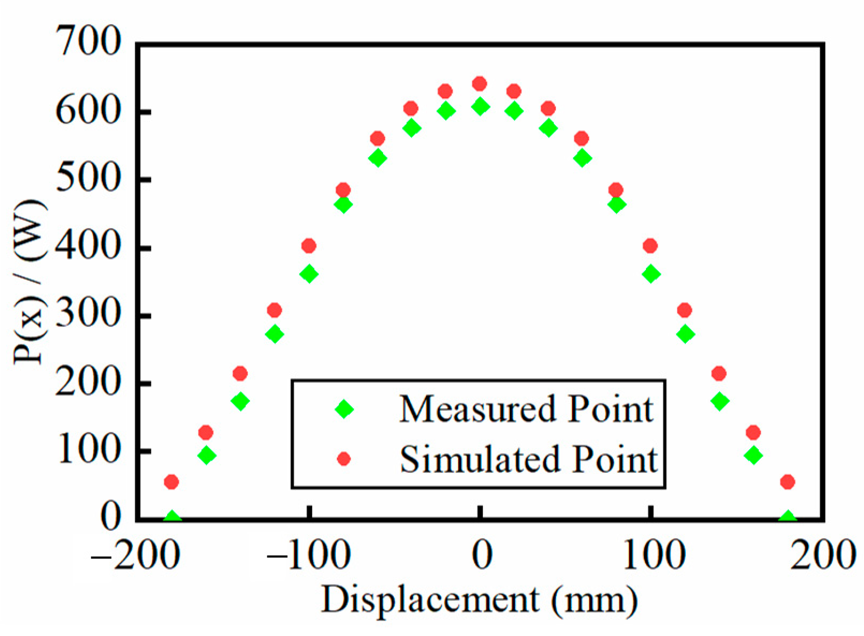
4.2. Waveform and Average Output Power

The waveforms for the alignment condition and the 100 mm offset condition are shown in Figure 10. The output power is 608 W and 362 W, respectively, which is ten percent different from the theoretical calculated values of 641 W and 402 W. Also, the measured output power at each position and the simulated power are shown in Figure 11, where it can be seen that the measured values match the simulated values well over the entire moving range. The average output power calculated using the quadratic fitting method is 302 W, which is 90.4% of the simulated value.

4.3. Comparisons to Other Solution

To verify the optimized design, two comparative ground-side coils were built and tested, and the comparative results are shown in Figure 12. In the first comparison group, the number of turns of the coil was reduced from 12 turns to 10 turns, while the length LT of the coil and the number N of arrangements remained unchanged. In the second control group, the length of the coil was increased from 320 to 400 mm, the number N of coils was changed to 8, and the turns n of the coil was unchanged. It can be seen that the reduction of the number of coil turns will reduce the transmission power of the system. Correspondingly, the increase of the coil length will increase the transmission power of the system. The difference between the measured and estimated efficiency, power is shown in Figure 12b; these differences are partly due to losses caused by inverter, rectifier and manufacturing variation. Overall, the power and efficiency test results of the system match with the results of the theoretical calculations, verifying the effectiveness of the method.

5. Conclusions

This paper presents a multi-objective design method for ground-side magnetic couplers that takes coupling fluctuations into account. Fluctuations in power due to variations in the coupling coefficient of short segmented coils are incorporated into the calculation process, which can help to evaluate the average transmission power of the whole system more accurately. The system is considered in terms of transmission power, transmission efficiency and construction cost. A comparison of the different coil forms shows that the chosen design solution has advantages in terms of efficiency and cost while meeting the power requirements. The optimization method has been validated by an IPT prototype with an average power of 304 W and an efficiency of 84.1%.

Author Contributions

Conceptualization & formal analysis, W.W.; Writing—review & editing, J.D.; Investigation, Z.W.; Funding acquisition, S.W. All authors have read and agreed to the published version of the manuscript.

Funding

Supported by the National Natural Science Foundation of China (Grant No. 52177207).

Conflicts of Interest

The authors declare no conflict of interest.

References

  1. Siqi, L.; Mi, C.C. Wireless Power Transfer for Electric Vehicle Applications. IEEE J. Emerg. Sel. Top. Power Electron. 2015, 3, 4–17. [Google Scholar] [CrossRef]
  2. Bagchi, A.C.; Kamineni, A.; Zane, R.; Carlson, R.B. Review and Comparative Analysis of Topologies and Control Methods in Dynamic Wireless Charging of Electric Vehicles. IEEE J. Emerg. Sel. Top. Power Electron. 2021, 9, 4947–4962. [Google Scholar] [CrossRef]
  3. Dai, X.; Jiang, J.-C.; Wu, J.-Q. Charging Area Determining and Power Enhancement Method for Multiexcitation Unit Configuration of Wirelessly Dynamic Charging EV System. IEEE Trans. Ind. Electron. 2018, 66, 4086–4096. [Google Scholar] [CrossRef]
  4. He, H.; Wang, S.; Liu, Y.; Jiang, C.; Wu, X.; Wei, B.; Jiang, B. Maximum Efficiency Tracking for Dynamic WPT System Based on Optimal Input Voltage Matching. IEEE Access 2020, 8, 215224–215234. [Google Scholar] [CrossRef]
  5. Tan, L.; Zhao, W.; Liu, H.; Li, J.; Huang, X. Design and Optimization of Ground-Side Power Transmitting Coil Parameters for EV Dynamic Wireless Charging System. IEEE Access 2020, 8, 74595–74604. [Google Scholar] [CrossRef]
  6. Bandyopadhyay, S.; Venugopal, P.; Dong, J.; Bauer, P. Comparison of Magnetic Couplers for IPT-Based EV Charging Using Multi-Objective Optimization. IEEE Trans. Veh. Technol. 2019, 68, 5416–5429. [Google Scholar] [CrossRef]
  7. Deng, J.; Zhang, Y.; Wang, S.; Wang, Z.; Yang, Y. The Design and Coupler Optimization of a Single-Transmitter Coupled Multi-Receiver Inductive Power Transfer System for Maglev Trains. IEEE Trans. Transp. Electrif. 2021, 7, 3173–3184. [Google Scholar] [CrossRef]
  8. Luo, Z.; Wei, X.; Pearce, M.G.S.; Covic, G.A. Multiobjective Optimization of Inductive Power Transfer Double-D Pads for Electric Vehicles. IEEE Trans. Power Electron. 2021, 36, 5135–5146. [Google Scholar] [CrossRef]
  9. Shi, W.; Dong, J.; Soeiro, T.B.; Riekerk, C.; Grazian, F.; Yu, G.; Bauer, P. Design of a Highly Efficient 20-KW Inductive Power Transfer System With Improved Misalignment Performance. IEEE Trans. Transp. Electrif. 2022, 8, 16. [Google Scholar] [CrossRef]
  10. Zhang, W.; Wong, S.-C.; Tse, C.K.; Chen, Q. An Optimized Track Length in Roadway Inductive Power Transfer Systems. IEEE J. Emerg. Sel. Top. Power Electron. 2014, 2, 598–608. [Google Scholar] [CrossRef]
  11. Zhang, P.; Saeedifard, M.; Onar, O.C.; Yang, Q.; Cai, C. A Field Enhancement Integration Design Featuring Misalignment Tolerance for Wireless EV Charging Using LCL Topology. IEEE Trans. Power Electron. 2021, 36, 3852–3867. [Google Scholar] [CrossRef]
  12. Li, Z.; Li, J.; Li, S.; Yu, Y.; Yi, J. Design and Optimization of Asymmetric and Reverse Series Coil Structure for Obtaining Quasi-Constant Mutual Inductance in Dynamic Wireless Charging System for Electric Vehicles. IEEE Trans. Veh. Technol. 2021, 71, 2560–2572. [Google Scholar] [CrossRef]
  13. Feng, H.; Dayerizadeh, A.; Lukic, S.M. A Coupling-Insensitive X-Type IPT System for High Position Tolerance. IEEE Trans. Ind. Electron. 2021, 68, 6917–6926. [Google Scholar] [CrossRef]
  14. Feng, H.; Cai, T.; Duan, S.; Zhao, J.; Zhang, X.; Chen, C. An LCC-Compensated Resonant Converter Optimized for Robust Reaction to Large Coupling Variation in Dynamic Wireless Power Transfer. IEEE Trans. Ind. Electron. 2016, 63, 6591–6601. [Google Scholar] [CrossRef]
  15. Liu, J.; Liu, Z.; Su, H. Passivity-Based PI Control for Receiver Side of Dynamic Wireless Charging System in Electric Vehicles. IEEE Trans. Ind. Electron. 2022, 69, 783–794. [Google Scholar] [CrossRef]
  16. Petersen, M.; Fuchs, F.W. Load Dependent Power Control in Series-Series Compensated Electric Vehicle Inductive Power Transfer Systems. In Proceedings of the 2014 16th European Conference on Power Electronics and Applications, IEEE, Lappeenranta, Finland, 26–28 August 2014; pp. 1–10. [Google Scholar]
  17. Liu, H.; Huang, X.; Tan, L.; Guo, J.; Wang, W.; Yan, C.; Xu, C. Dynamic Wireless Charging for Inspection Robots Based on Decentralized Energy Pickup Structure. IEEE Trans. Ind. Inform. 2018, 14, 1786–1797. [Google Scholar] [CrossRef]
  18. Li, S.; Li, W.; Deng, J.; Nguyen, T.D.; Mi, C.C. A Double-Sided LCC Compensation Network and Its Tuning Method for Wireless Power Transfer. IEEE Trans. Veh. Technol. 2015, 64, 2261–2273. [Google Scholar] [CrossRef]
  19. Li, W.; Zhao, H.; Li, S.; Deng, J.; Kan, T.; Mi, C.C. Integrated ${LCC} $ Compensation Topology for Wireless Charger in Electric and Plug-in Electric Vehicles. IEEE Trans. Ind. Electron. 2015, 62, 4215–4225. [Google Scholar] [CrossRef]
  20. Mills, M.K. Self Inductance Formulas for Multi-Turn Rectangular Loops Used with Vehicle Detectors. In Proceedings of the 33rd IEEE Vehicular Technology Conference, Toronto, ON, Canada, 25–27 May 1983; pp. 65–73. [Google Scholar]
  21. Lu, F.; Hofmann, H.; Deng, J.; Mi, C. Output Power and Efficiency Sensitivity to Circuit Parameter Variations in Double-Sided LCC-Compensated Wireless Power Transfer System. In Proceedings of the 2015 IEEE Applied Power Electronics Conference and Exposition (APEC), Charlotte, NC, USA, 15–19 March 2015; pp. 597–601. [Google Scholar]
  22. Steinmetz, C.P. On the law of hysteresis. Proc. IEEE 1984, 72, 197–221. [Google Scholar] [CrossRef]
Figure 1. The structure of a short−segmented DWPT system.
Energies 15 06075 g001
Figure 2. Mutual−inductance model-based analytical circuit of the LCC−LCC compensation topology.
Energies 15 06075 g002
Figure 3. Diagram of a short segmented DWPT system.
Energies 15 06075 g003
Figure 4. Coupling of coils with different turns in different positions.
Energies 15 06075 g004
Figure 5. (a) Relationship between P(x) with displacement. (b) Relationship between P(t) with time. (c) Power fluctuation curve as the system passes through the charging road.
Energies 15 06075 g005
Figure 6. Multi-objective optimization process of DWPT systems.
Energies 15 06075 g006
Figure 7. Multi–objective optimizing results of DWPT system: (a) power vs. total cost; (b) power vs efficiency with different transmitter coil construction.
Energies 15 06075 g007
Figure 8. Fundamental prototype of a DWPT system.
Energies 15 06075 g008
Figure 9. Comparison of measured and simulated mutual inductance.
Energies 15 06075 g009
Figure 10. Waveform of the system: (a) alignment condition; (b)100 mm offset condition.
Energies 15 06075 g010
Figure 11. Comparison of measured and simulated transfer power.
Energies 15 06075 g011
Figure 12. Comparison between estimated and measured: (a) power; (b) efficiency.
Energies 15 06075 g012
Table 1. System specifications and constructive limitations.
VarDescriptionValue
UinTransmitter input DC voltage100 V
UoutReceiver input DC voltage100 V
fDWPT system frequency85 kHz
αAir gap80 mm
LroadLength of the supply road4000 mm
WrecWidth of the receiver coil40 mm
LrecLength of the receiver coil200 mm
VmaxMaximum vehicle speed1 m/s
Pave_vPower consumption per kilometer250 W
Table 2. Design physical variables and value range.
VarDescriptionValue
LTLength of the transmitting coil/mm[200:40:400]
nNumber of turns of transmitting coil[6:2:12]
NNumber of the transmitting coils[5:1:20]
Table 3. Design price variables and value.
DescriptionValue
Unit price of Litz wire¥ 4.5/m
Unit price of ferrite¥ 4 × 10⁻⁴/mm3
Unit price of capacitors(100 nF)¥ 40 each
Unit price of capacitors(10 nF)¥ 13.48 each
Unit price of capacitors(1 nF)¥ 6.17 each
Table 4. Physical parameters of selected point.
VarDescriptionValue
LTLength of the transmitting coil/mm320
nNumber of turns of transmitting coil12
NNumber of the transmitting coils9
kmaxMaximum coupling coefficient0.173
PaveAverage transfer power334 W
ƞTransfer efficiency87.6%
SThe total cost¥ 3537.1
Table 5. Circuit Parameters of System.
VarDescriptionValue
L1Ground-side inductance108 μH
L2Vehicle-side inductance53 μH
Lf1, Lf2Compensated inductance16.86 μH, 16.86 μH
C1, C2Parallel compensated capacitor207.94 nF, 207.94 nF
Cf1, Cf2Series compensated capacitor38.46 nF, 97.01 nF
Publisher’s Note: MDPI stays neutral with regard to jurisdictional claims in published maps and institutional affiliations.

