Article

A Battery Thermal Management System Coupling High-Stable Phase Change Material Module with Internal Liquid Cooling

School of Materials and Energy, Guangdong University of Technology, Guangzhou 510006, China
*
Author to whom correspondence should be addressed.
Energies 2022, 15(16), 5863; https://doi.org/10.3390/en15165863
Submission received: 11 July 2022 / Revised: 5 August 2022 / Accepted: 9 August 2022 / Published: 12 August 2022
(This article belongs to the Section J1: Heat and Mass Transfer)

Abstract

:
In this work, we develop a hybrid battery thermal management (BTM) system for a 7 × 7 large battery module by coupling an epoxy resin (ER)-enhanced phase change material (PCM) module with internal liquid cooling (LC) tubes. The supporting material of ER greatly enhances the thermal stability and prevents PCM leakage under high-temperature environments. In addition, the other two components of paraffin and expanded graphite contribute a large latent heat of 189 J g−1 and a high thermal conductivity of 2.2 W m−1 K−1 to the PCM module, respectively. The LC tubes can dissipate extra heat under severe operating conditions, demonstrating effective secondary heat dissipation and avoiding heat storage saturation of the module. Consequently, during the charge-discharge tests under a 40 °C ambient temperature, the temperature of the PCM-LC battery module could be maintained below 40.48, 43.56, 45.38 and 47.61 °C with the inlet water temperature of 20, 25, 30 and 35 °C, respectively. During the continuous charge-discharge cycles, the temperature could be maintained below ~48 °C. We believe that this work contributes a guidance for designing PCM-LC-based BTM systems with high stability and reliability towards large-scale battery modules.

1. Introduction

The increasing environmental pollution and energy crisis promote the fast development of electric vehicles (EVs) in the past decade [1]. Lithium-ion batteries (LIBs) are widely used to assemble the battery modules in EVs by virtue of their high energy density, long cycle life and negligible memory effect [2]. Nevertheless, LIBs present particular sensitivity to the operating temperature [3]. An over-high temperature or over-large temperature difference (ΔT) may aggravate battery material degradation, thus shortening the lifespan of the LIBs [4]. Furthermore, in extreme cases, thermal runaway of the LIBs occurs when the heat accumulates seriously, leading to even explosion and other thermal hazards [5]. Generally, it is believed that the maximum ΔT (ΔTmax) and maximum temperature (Tmax) of the battery modules should be maintained below 5 and 50 °C, respectively [6]. Therefore, designing a battery thermal management (BTM) system to keep the Tmax and ΔTmax below the aforementioned values, is an effective strategy to improve the service life and safety of battery modules.
Among many BTM systems of battery modules, forced air cooling possesses low cooling efficiency and poor temperature-uniform performance for large battery modules [7]. Although liquid cooling (LC) demonstrates excellent heat dissipation capacity and is widely used in practical applications, it is still criticized for its complex structure and coolant leakage risk [8]. The temperature-control technology based upon phase change material (PCM) has attracted enormous attention in BTM systems due to its high cooling efficiency, simple installation and passive cooling property compared to forced air cooling and liquid cooling [9]. In order to conquer the intrinsic drawback of pure PCMs, numerous works are focused on designing novel composite PCMs (CPCMs) to meet the requirements of BTM [10]. For instance, Fan et al. [11] prepared a paraffin/carbon nanofillers CPCM. They found that the thermal conductivity of the CPCM could be enhanced by increasing mass fractions of nanofillers. Yang et al. [12] constructed a metallic thermal conductive skeleton for CPCM by simply filling paraffin (PA) into the a copper foam with a pore size 2–3 mm and a porosity of 97%.
However, in practical applications, the PCM-based BTM technology still faces a challenge [13]. Under harsh working conditions, the battery module produces a large amount of heat [14]. Owing to the limited heat storage density of PCM, (localized) heat storage saturation of the PCM module appears, and consequently loses the temperature-control ability, leading to a continuous temperature rise in partial batteries [15]. Thus, coupling an active secondary heat dissipation technology with the PCM module, in other words, constructing a hybrid BTM system, is an effective strategy to solve this issue [16].
Among various secondary heat dissipation technologies, LC is the most commonly used technology for the PCM module [17]. Generally speaking, the previous works relevant to the hybrid PCM-LC system for cylindrical battery modules can be classified into three categories (Table 1):
(1)
Internal heat dissipation. The cylindrical cells and LC components such as LC channels and LC plates are simultaneously installed into the PCM module.
(2)
External heat dissipation. The cylindrical cells are inserted into a regular PCM module, and then LC components are installed on the outer surface of the PCM module.
(3)
Single-unit heat dissipation. Each cylindrical cell is inserted into a well-designed tubular PCM unit. Then, special LC components are designed to match the curve surface of these “cell-PCM” units, assembling into a battery module.
The single-unit heat dissipation strategy (category (3)), in spite of its novel structure and high cooling performance, is still far from practical application because of its complex structure, tedious assembling process and the difficulty to process tubular PCM units. Therefore, experimental investigations are only focused on external and internal heat dissipation strategies. Ling et al. [27] attached four LC plates on the side-surfaces of a PCM module consisting of 20 cylindrical cells. Li et al. [28] installed two heat sinks on the opposite surfaces of a PCM module assembled with 15 cylindrical cells. Wu et al. [29] placed a mini-channel cold plate at the bottom of the PCM module. However, owing to the diversified heat transfer distances from the cells located in different positions to the outer LC components, external heat dissipation may lead to a relatively non-uniform temperature distribution, especially for large-scaled battery modules with large dimensions. In addition, the LC components outside the PCM module occupy extra space, decreasing the volumetric energy density of the battery modules. Constructing an internal heat dissipation structure is considered as a more suitable strategy to reduce the temperature difference and increase the volumetric energy density of the battery module. For example, Lebrouhi et al. [23] inserted 9 aluminum tubes into the PCM module consisting of 24 cylindrical cells. Kong et al. [18] holistically inserted 24 commercial cylindrical cells and 5 S-shaped aluminum tubes into the PCM matrix. Zhao et al. [21] added a ribbon-shaped metallic cooling channel into the PCM module containing 20 cylindrical cells.
Although significant progresses have been made by the above designs of the hybrid PCM-LC systems, there still remain obvious problems in the previously reported experimental investigations: (1) relatively small-scale battery modules assembled by no more than 25 cells are used for the experimental tests, in which serious heat accumulation phenomenon might not appear; (2) pure PCMs or binary CPCMs (adding expanded graphite (EG) or metallic component into pure PCM) are used to prepare the PCM module. Undoubtedly, such PCM modules are thermally instable. Under harsh working environments like high ambient temperature and/or high-rate/repeated charge-discharge, PCM leakage and module deformation/collapse will inevitably occur in large battery modules with more severe heat generation [33]. These problems greatly reduce the feasibility of the hybrid PCM-LC systems in practical applications.
Therefore, this work aims to construct an efficient and high-stable PCM-based BTM system suitable for large-scale battery modules. We assembled a relatively large battery module consisting of 49 cylindrical cells as the cooling target and design a corresponding hybrid cooling structure by coupling a high stable epoxy resin (ER)-enhanced CPCM module with internal LC tubes. As highlighted here, under severe operating conditions, the ER component introduced in the CPCM acts as a thermosetting supporting material to enhance the thermal stability and prevent PCM leakage of the large CPCM module. The high thermal conductivity benefiting from the EG component may transfer the extra heat to the liquid cooling tubes, avoiding thermal storage saturation in the CPCM module. For example, under a simulated harsh working condition with a 40 °C ambient temperature and 3 C discharge rate, the obtained hybrid PCM-LC BTM system delivers outstanding cooling and temperature-uniformed performances compared to the PCM-air cooling structure.

2. Experimental Section

2.1. Materials

PA was obtained from Shanghai Joule wax Co., Ltd., Shanghai, China. Natural graphite sheets were purchased from Qingdao Yanhai carbon materials Co., Ltd., Qingdao, China. ER was purchased from Hunan BAXIN brother Materials Co., Ltd., Changsha, China. All the materials were used as received without further purification. The 18650 cylindrical LIBs were obtained from Tianjin Lishen Battery Co., Ltd., Tianjin, China.

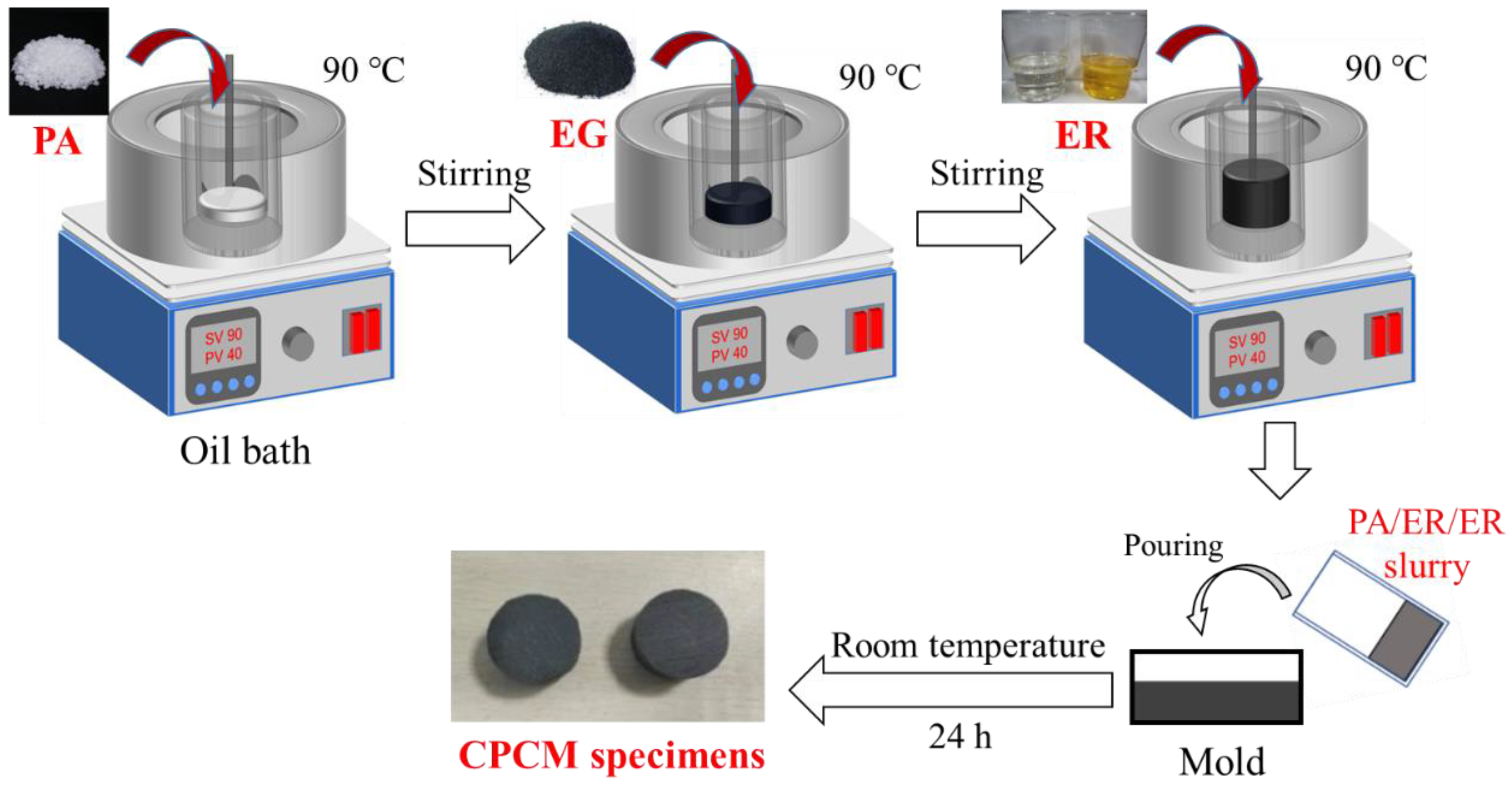
2.2. Preparation and Characterizations of the CPCM

In order to endow the resultant PCM module with a high thermal stability and thermal conductivity, we prepared a CPCM by selecting PA, EG and ER to be the PCM, thermal conductive filler and thermosetting supporting material, respectively. The preparation of PA/EG/ER-based CPCM adopted a physical-blending method shown in Figure 1. Pure PA was added into a container placed in an oil bath pot at 90 °C (DF-101S, Shanghai mutual Instrument Co., Ltd., Shanghai, China) under mechanical stirring (JJ-1 200 W, Xuri experimental instrument factory) until PA was completely melted. Then, EG obtained from natural graphite sheets was added. After stirring for 2 h, ER was added into the mixture and kept stirring for another 0.5 h, obtaining a stable and uniform slurry. The mass proportions of EG and ER in the slurry were 5.5 wt% and 15 wt%, respectively. Finally, the slurry was poured into the molds with various dimensions and cooled to room temperature. After cured for 24 h, CPCM specimens with various dimensions were obtained for a thermal conductivity test, mechanical test and DSC test.
A thermal conductivity analyzer (LFA447, NETZSCH-Gerätebau GmbH, Selbu, Germany) and a differential scanning calorimeter (DSC, METTLER TOLEDO DSC3, Zurich, Switzerland) were utilized to test the thermal conductivity, latent heat and phase change temperature of the CPCM. The mechanical strength of PA and CPCM was measured with a Hounsfield universal testing machine.

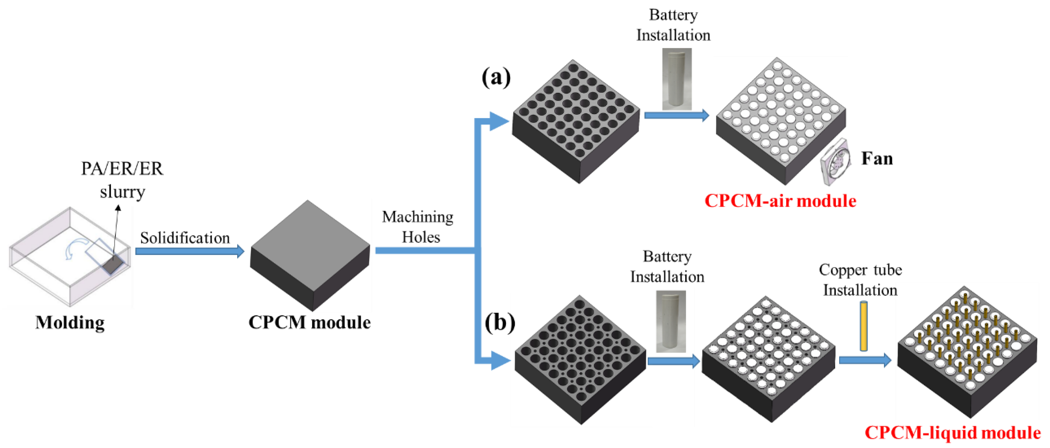
2.3. Structural Design of the Battery Module Cooled by CPCM Coupled with Forced Air Convection

Figure 2a shows the structural design of the battery module cooled by CPCM coupled with forced air convection. In brief, the aforementioned slurry-state PA/EG/ER mixture was poured into a cuboid mold with dimensions of 162 × 162 × 55 mm3 and cooled to room temperature. After the mixture solidified to a cuboid CPCM module, 49 holes (7 holes in row and 7 holes in column) were drilled on the upper surface (162 × 162 mm2), which were then used for installing the 18650 cylindrical cells. The diameter of each hole was 18.5 mm, and the distance between the geometric centers of every two adjacent holes was 23 mm. After that, 49 cylindrical LIBs were inserted into the holes, and connected into 7 series (S) × 7 parallel (P). Table 2 shows the detailed parameters of the LIBs. Subsequently, a fan (Yueqing electronic equipment Co., Ltd., Guangzhou, China with a size of 80 mm × 80 mm) connected to a DC power supply (YK-CD3050, Yuku network equipment Co., Ltd., Guangzhou, China) was installed 30 cm away from the side surface of the CPCM module. The airflow velocity was measured by a digital anemometer (Shenzhen jumaoyuan Technology Co., Ltd., Shenzhen, China). For convenience, this battery module cooled with CPCM and forced air convection was abbreviated as the CPCM-air module.

2.4. Structural Design of the Battery Module Cooled by CPCM Coupled with LC

Figure 2b displays the structural design of the battery module cooled by CPCM coupled with LC. Likewise, according to the procedure in Section 2.2, a cuboid CPCM module was prepared, and 49 holes were machined on the module to install the cells. Subsequently, 36 relatively small holes (6 holes in row and 6 holes in column) (Φ4 mm) were also machined in every geometric center of 4 adjacent cells for inserting the copper tubes. After that, 49 cylindrical LIBs and 36 copper tubes were then inserted in the holes, respectively. The LIBs were also connected with a configuration of 7 S × 7 P. Flowing water with different temperatures was used as the coolant. The copper tubes were connected to a water pump (Zhongshan HAIGUAN Electric Appliance Co., Ltd., Zhongshan, China). The temperatures of the inlet water were set to be 20, 25, 30 and 35 °C, respectively. For convenience, this battery module cooled with CPCM, and water flow was abbreviated as the CPCM-liquid module.

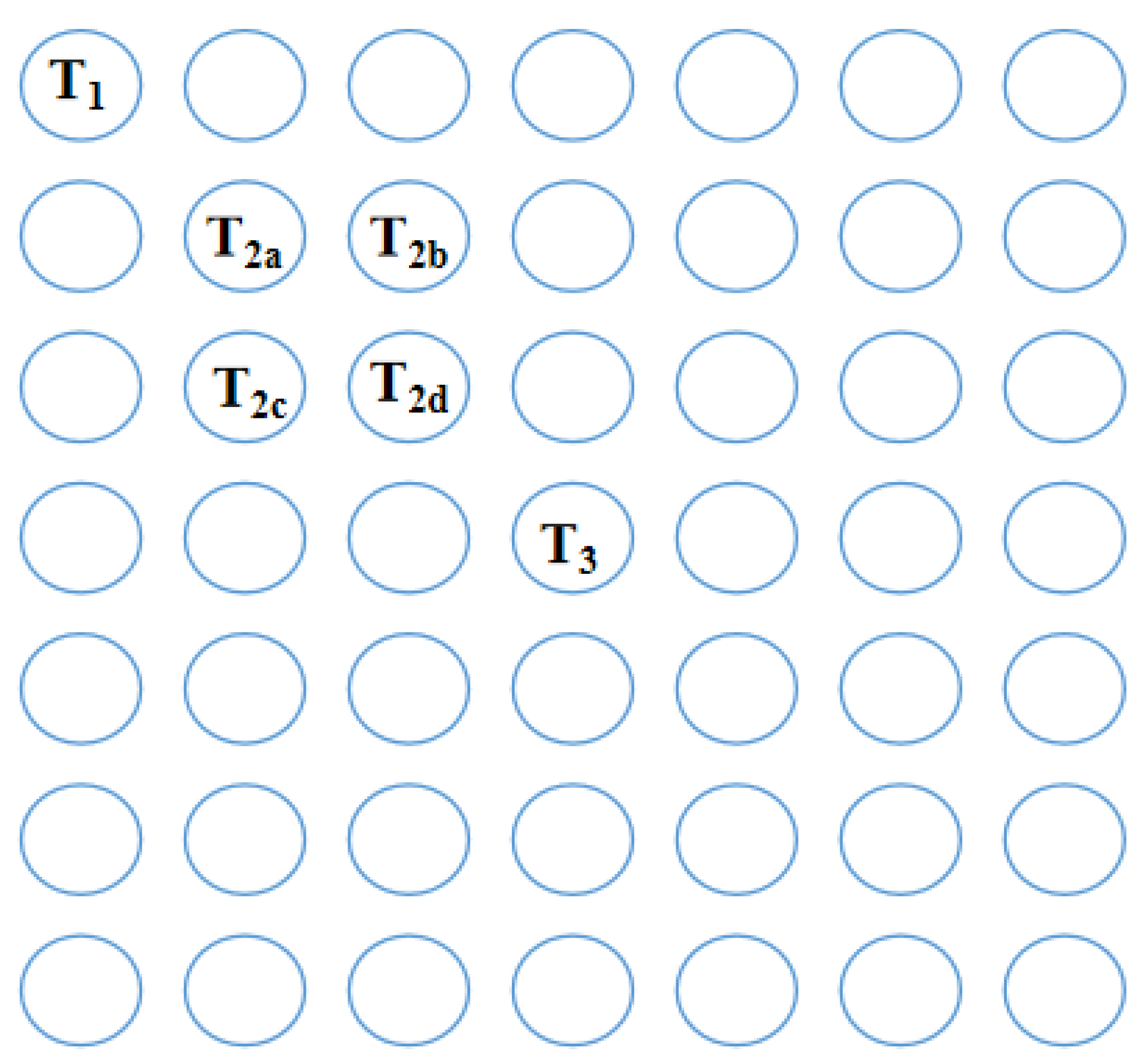
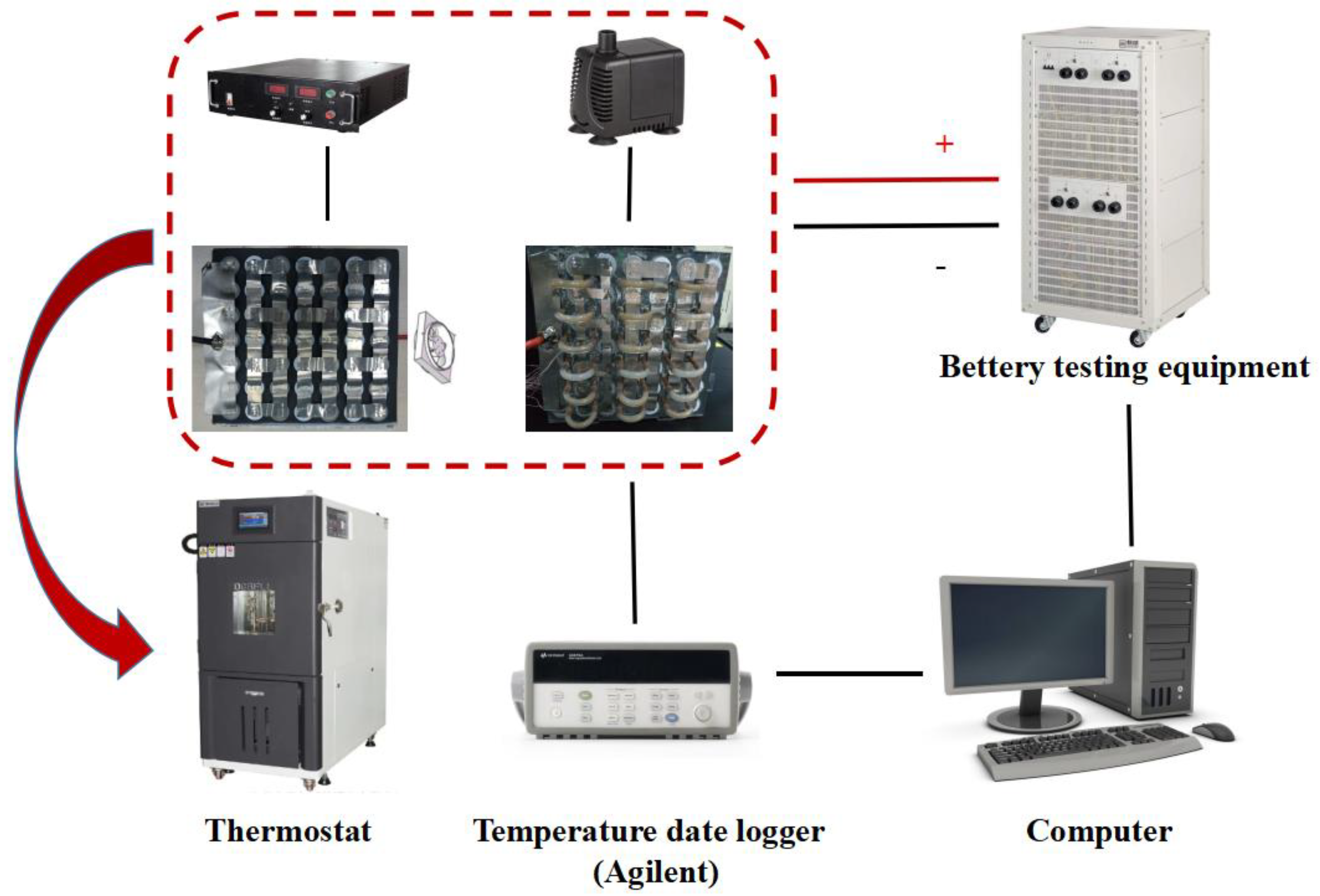
2.5. Setup of the Experimental Testing Platform

In order to test the temperature variation of the battery modules, 6 thermocouples (T-type, accuracy of ± 0.1 C, USA) were attached on the center of the surface of the cylindrical cells, and the distribution of thermocouples in the battery modules are shown in Figure 3. The tested temperatures of the six cells were denoted as T1, T2a, T2b, T2c, T2d and T3. As shown in Equation (1), T2 represented the average value of T2a, T2b, T2c and T2d. At the same time, according to Equations (2) and (3), the difference between the T3 of the central battery and T1 of the corner battery was recorded as ∆T13, and the difference between the T3 and T2 was recorded as ∆T23. T3 reflected the temperature variation of the whole module, and thus was used to evaluate the heat dissipating performance of the cooling module, because the central battery usually presented the highest temperature. ∆T13 and ∆T23 were used as indexes to evaluate the temperature-uniform capability of the BTM system.
T 2 = ( T 2 a + T 2 b + T 2 c + T 2 d ) / 4
Δ T 13 = T 3 T 1
Δ T 23 = T 3 T 2
For the temperature-control tests, the experimental setup is displayed in Figure 4. The battery modules were put in a thermostat, and the temperature of the thermostat was set to be 40 °C to simulate a high ambient temperature environment. The charging process of the battery module adopted a constant current combined with constant voltage mode, and the discharging process adopted a constant current mode. Charging-discharging parameters are displayed in Table 3.

2.6. Uncertainty Analysis

The uncertainty of this work is derived from the measurement error of the instrument, including the temperature, voltage, internal resistance and air velocity. According to the previous investigations [34,35], the temperature error (σT), internal resistance error (σR), voltage error (σV), and air velocity error (σv) can be calculated depending on the following Equations (4)–(7):
σ T = ± ( σ t 2 + σ c 2 )
σ V = ± i = 1 N = 5 ( V t ( i ) V a ) 2 N
σ R = ± i = 1 N = 5 ( R t ( i ) R a ) 2 N
σ v = ± 1 N 1 i = 1 N = 5 ( v t   v a ) 2
where, σt, σc, Rt(i), vt(i), Vt(i), Ra, va, and Va were the maximum error of thermocouple, collection error (σc) of the temperature, tested resistance, voltage, velocity, average values of resistance, air velocity and voltage, respectively; The calculating results are presented in Table 4.

3. Results and Discussion

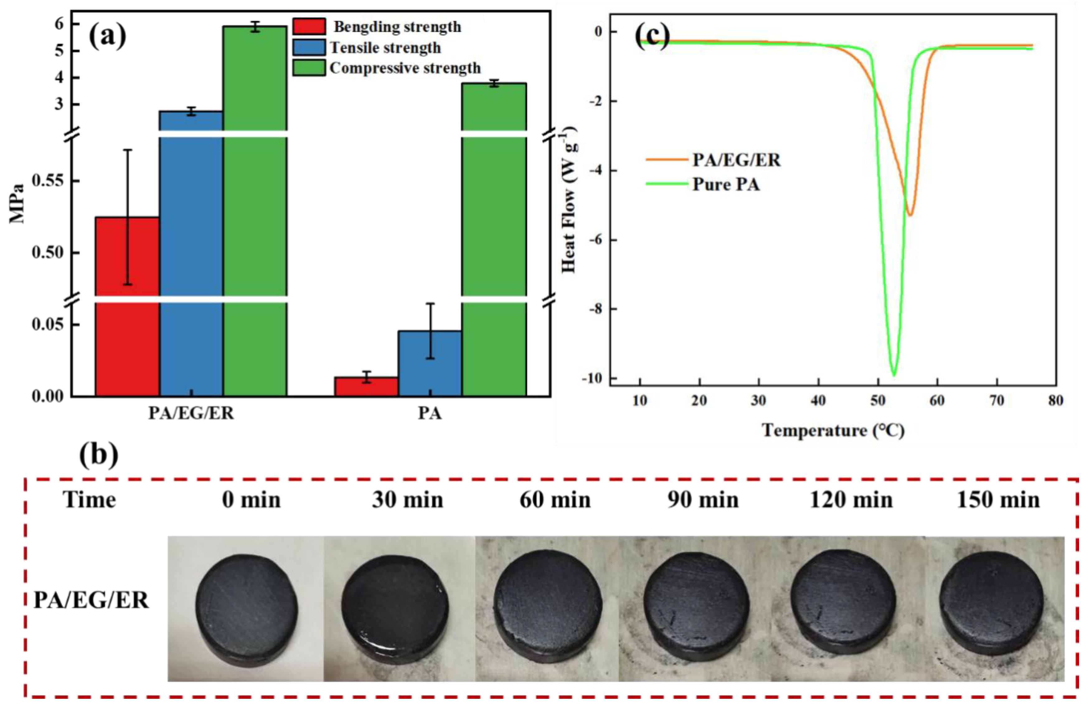
3.1. Characterizations of the CPCM

In this work, PA is selected as the PCM because of its low cost (~6 USD kg−1) and high latent heat (251.2 J g−1), which ensures a high thermal storage density [36]. However, pure PA is not yet suitable for BTM application owing to its thermal conductivity of 0.23 W m−1 K−1, poor mechanical strength and melting phenomenon after phase change occurs [37]. Thereby, EG is adopted to enhance the thermal conductivity of the CPCM due to its low density and well dispersed ability [38]. Additionally, benefiting from the thermosetting property and room-temperature solidification ability, ER is selected as the supporting material with the aim of improving the mechanical strength and thermal stability of the obtained CPCM specimen/module [39].
After being incorporated with 5.5 wt% of EG, the CPCM demonstrates a greatly increased thermal conductivity from 0.23 to 2.2 W m−1 K−1, which results from the continuous thermal conductive framework formed by EG. On the other hand, the ER component acts as a supporting skeleton to enhance the mechanical strength and thermal stability of the CPCM after phase change occurs. Figure 5a shows the tensile strength, bending strength and compressive strength of the specimens. Each measurement was performed three times. It can be clearly seen that the average values of the bending strength, tensile strength and compressive strength of the CPCM are 0.52, 2.74 and 5.91 MPa, which are 0.40, 2.69 and 2.12 MPa higher than those of pure PA, respectively. After placing a cake-shaped CPCM at a high ambient temperature of 50 °C for 150 min (above the phase change temperature), the specimen still showed a stable shape without any deformation and leakage trace (Figure 5b), which confirms the great thermal stability of the CPCM benefiting from the ER supporting skeleton. Figure 5c demonstrates the DSC curves of the PA and obtained CPCM. It was found that compared to pure PA, the CPCM (PA/EG/ER) possesses a relatively low phase change onset temperature of 45.6 °C and a decreased latent heat of 189 J g−1. This is because the additional components in the CPCM will reduce the latent heat, and the reinforced thermal conductivity accelerates the heat penetration speed from the tested sample towards the calorimeter during the tests. Such superior thermo-physical properties, coupled with the good thermal stability, are suitable for the CPCM to be used in BTM applications.

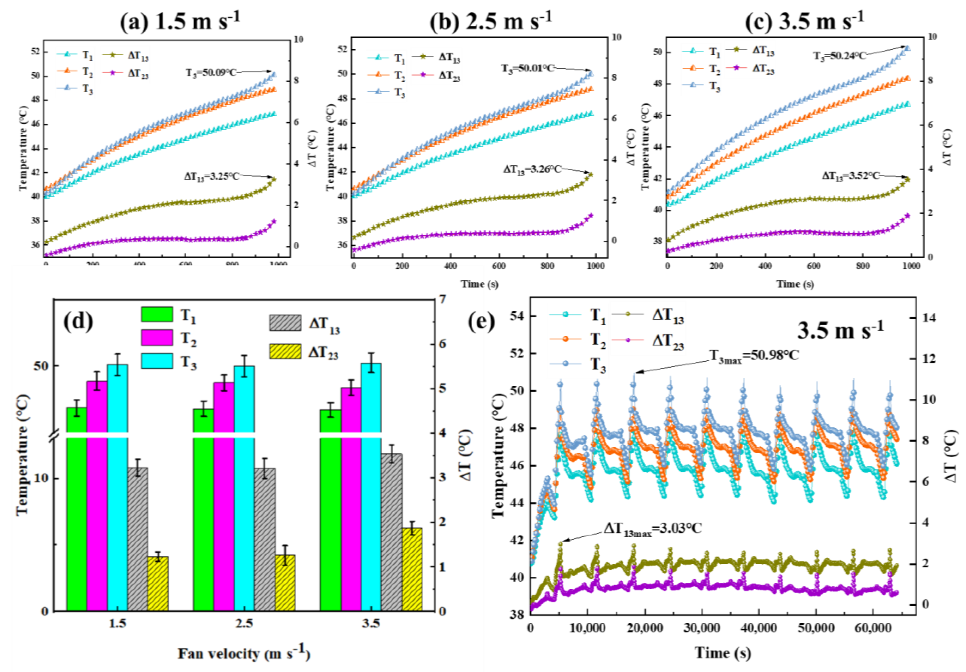
3.2. The Temperature-Control Performance of the CPCM-Air Module

All the temperature-control tests were executed under an ambient temperature of 40 °C with a 3 C discharge rate of the battery module. Figure 6a shows the temperature and ΔT variation curves of the CPCM-air module with an air velocity of 1.5 m s−1. Because the corner battery is close to the outer heat dissipating surface of the module, it presents the slowest heating rate and thereby results in the lowest temperature value (T1) at the termination of discharge. Meanwhile, the T3 of the center battery delivers the fastest heating rate and leads to the highest value at the termination of discharge. This is because of the more severe heat accumulation at the center of the battery module. As a result, ΔT13 is much larger than ΔT23 during the entire discharge protocol. The maximum temperature of the central battery is up to 50.09 °C, and the temperature difference (ΔT13) between the center battery and the corner battery reaches 3.25 °C.
Subsequently, we tried to increase the air velocity to 2.5 m s−1 to enhance the heat dissipating effect of the module. As displayed in Figure 6b, unfortunately, no obvious reduction of the temperature rises and ΔT can be observed. The T3 of the central battery still remains at 50.01 °C, while the maximum ΔT13 is comparable to that under the air velocity of 1.5 m s−1. This phenomenon can be ascribed to the relatively low heat transfer coefficient between air flow and the relatively small outer surface of the bulk CPCM module. As we further increased the air velocity to 3.5 m s−1, similar phenomena were obtained (Figure 6c). The T3 of the central battery and ΔT13 are still up to 50.24 and 3.56 °C, respectively. The slightly increased ΔT13 with an increase of the air velocity results from the faster heat dissipating rate of the corner battery at a higher air velocity. Then, the CPCM-air module was executed by 10 charge-discharge cycles at a discharge rate of 3 C with an air velocity of 3.5 m s−1 (Figure 6e). During the cycles, T3 of the central battery reaches a maximum value of 50.98 °C, and the ΔT13 between the central battery and the corner battery is up to 3.03 °C. Overall, the relatively low heat dissipating efficiency of the forced air convection is because the bulk and compact CPCM module lacks airflow channels and outer surface for secondary heat exchange. Therefore, the CPCM-liquid module was designed by constructing water flow channels inside the CPCM module.

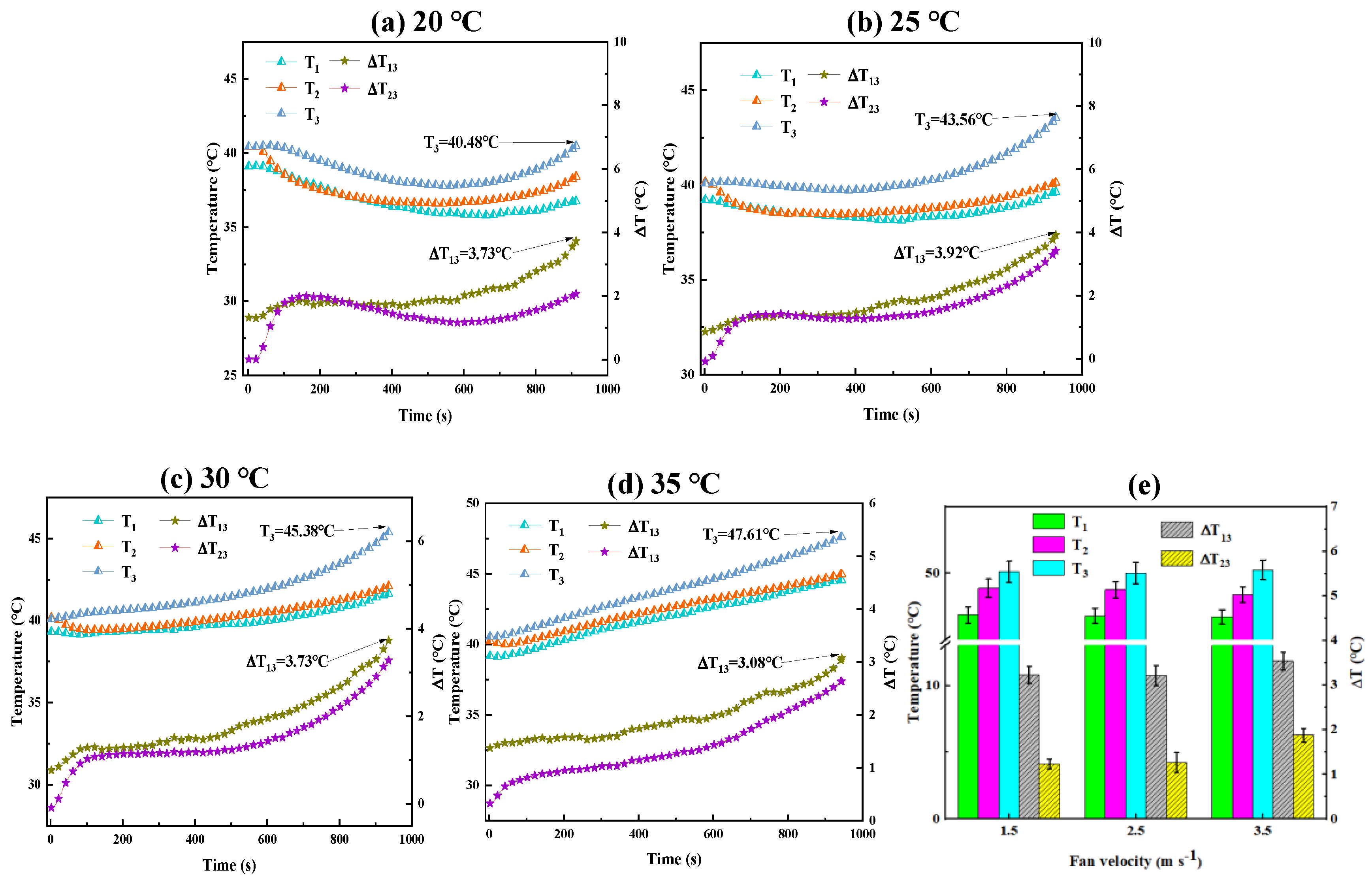
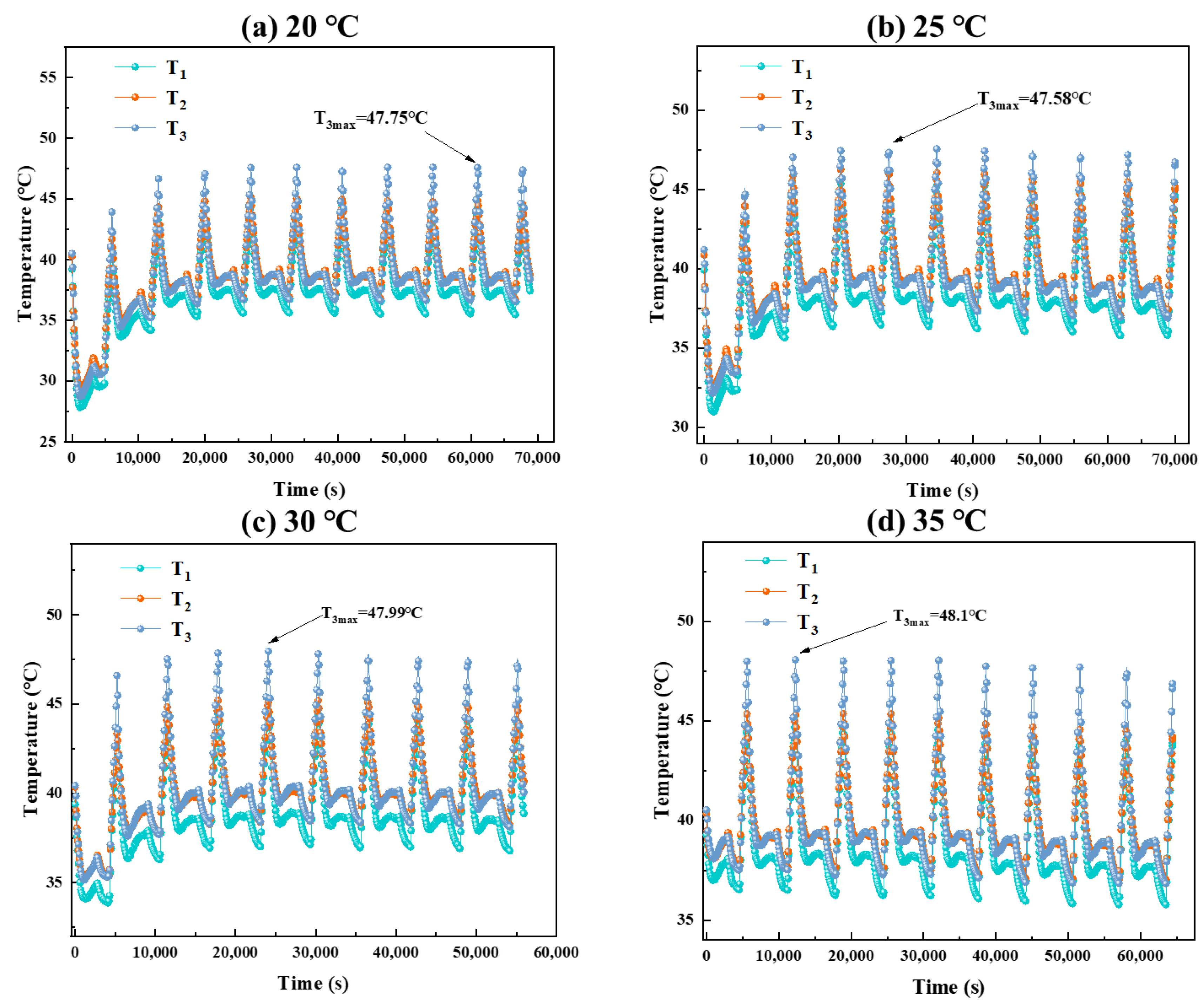
3.3. Temperature-Control Performance of the CPCM-Liquid Module

Figure 7 presents the ΔT and temperature curves of the CPCM-liquid module with various water temperatures of 20, 25, 30 and 35 °C at a 3 C discharge rate. With the lowest inlet water temperature of 20 °C, the temperatures of the whole battery module including T1, T2 and T3 decrease first and then increase. This can be explained as follows: the temperature of the inlet water (20 °C) is far lower than the initial temperature of the battery module (equivalent to ambient temperature of 40 °C), and thus the temperature of the module decreases first. Then, as the generated heat accumulates continuously, the temperature of the module switches to an increasing trend. At the termination of discharge, T3 presents the highest value of 40.48 °C due to heat accumulation, which is comparable with the ambient temperature, and the corresponding ΔT13 is 3.73 °C.
When the inlet water temperature is raised to 25 °C, all the temperatures show similar decreasing and then increasing trends as above. The slightly decreasing extent results from the higher inlet water temperature. At the termination of discharge, T3 and ΔT13 increase to 43.56 and 3.92 °C, respectively. As the inlet water temperature is further increased to 30 and 35 °C, the initial decreasing trend of T3 disappears because the water temperature is close to the ambient temperature. Consequently, the T3 reaches 45.38 and 47.61 °C, respectively. Interestingly, ΔT13 demonstrates a decreasing trend as increasing the inlet water temperature, i.e., 3.73 and 3.08 °C with the water temperature of 30 and 35 °C, respectively. This phenomenon is because while the temperature of the inlet water turns closer to the ambient temperature, the heating rate of the corner battery increases and will be closer to that of the center cell.
The main purpose of constructing this hybrid PCM-LC system is to meet the cooling and stability demands of relatively large-size battery modules, particularly under harsh working environments. Therefore, the charge–discharge of the CPCM-liquid module at high discharge rate (3 C) and high ambient temperature (40 °C) was then executed for 10 continuous cycles. As evidenced in Figure 8, it is clearly seen that the CPCM-liquid module demonstrates different heating rate and maximum temperature with various inlet water temperatures at the first charge–discharge cycle. Nevertheless, after thermal equilibrium at the subsequent cycles, comparable maximum temperature at around 48 °C is obtained. These aforementioned results strongly prove that the as-designed CPCM-liquid module possesses great feasibility and reliability towards large cylindrical battery modules, even under extreme working conditions. This outstanding performance not only derived from the thermal storage performance of the CPCM module and the high heat dissipating capability of the internal LC strategy, but also benefits from the high thermal stability of the CPCM module.

4. Conclusions

In order to construct an efficient and high-stable PCM-based BTM system suitable for practical applications, we assembled a relatively large battery module and designed a corresponding hybrid cooling structure by coupling a high stable ER-enhanced CPCM module with internal LC tubes. The ER component introduced in the CPCM acts as a thermosetting supporting material to enhance the thermal stability and prevent PCM leakage of the large CPCM module under harsh working environments. Moreover, besides the high latent heat of the CPCM (189 J g−1) that absorbs abundant generated heat, the high thermal conductivity (2.2 W m−1 K−1) of the CPCM plays a crucial role in transferring the extra heat to the water cooling tubes, which avoids heat storage saturation of the module. Under a 40 °C ambient temperature, the maximum temperatures of the CPCM-air module with various air velocities always exceed 50 °C at a high discharge rate of 3 C. By contrast, the CPCM-liquid module demonstrates better cooling performance by controlling the maximum temperature at much lower values. For instance, with the inlet water temperature of 20, 25, 30 and 35 °C, the maximum temperature of the CPCM-liquid module is 40.48, 43.56, 45.38 and 47.61 °C, respectively. During the continuous 10 charge–discharge cycles, the temperature of the module can be maintained below ~48 °C. We anticipate that this new strategy would promote the progress of the PCM cooling technology for BTM applications.

Author Contributions

Conceptualization, X.Y. and X.L.; Data curation, C.M., X.W. and X.L.; Formal analysis, C.M.; Investigation, C.M.; Methodology, C.M. and X.Y.; Resources, G.Z., X.Y. and X.L.; Supervision, G.Z., X.Y. and X.L. All authors have read and agreed to the published version of the manuscript.

Funding

This work was funded by the Basic and Applied Basic Research Fund of Guangdong Province (2021B1515130008).

Institutional Review Board Statement

Not applicable.

Informed Consent Statement

Not applicable.

Conflicts of Interest

The authors declare no conflict of interest.

Nomenclature

PCMphase change material
BTMbattery thermal management
CPCMcomposite PCM
EVselectric vehicles
LIBslithium-ion batteries
ΔTtemperature difference
Tmaxmaximum temperature
PAparaffin
EGexpanded graphite
ERepoxy resin
DCdirect current
DSCdifferential scanning calorimeter
ΔTmaxmaximum ΔT
LCliquid cooling

References

  1. Wu, W.; Wang, S.; Wu, W.; Chen, K.; Hong, S.; Lai, Y. A critical review of battery thermal performance and liquid based battery thermal management. Energy Convers. Manag. 2019, 182, 262–281. [Google Scholar] [CrossRef]
  2. Worwood, D.; Marco, J.; Kellner, Q.; Hosseinzadeh, E.; McGlen, R.; Mullen, D.; Lynn, K.; Greenwood, D. Experimental Analysis of a Novel Cooling Material for Large Format Automotive Lithium-Ion Cells. Energies 2019, 12, 1251. [Google Scholar] [CrossRef]
  3. Xie, J.; Wang, Y.; He, S.; Zhang, G.; Liu, X.; Yang, X. A simple cooling structure with precisely-tailored liquid cooling plate for thermal management of large battery module. Appl. Therm. Eng. 2022, 212, 118575. [Google Scholar] [CrossRef]
  4. Lv, Y.; Yang, X.; Zhang, G. Durability of phase-change-material module and its relieving effect on battery deterioration during long-term cycles. Appl. Therm. Eng. 2020, 179, 115747. [Google Scholar] [CrossRef]
  5. Li, S.; Shironita, S.; Sone, Y.; Hosono, E.; Asakura, D.; Umeda, M. Constant-rate heating-induced thermal runaway in 18650-type Li-ion cells charged/discharged at 1 °C: Effect of undischargeable Li at anode. J. Power Sources 2021, 505, 230082. [Google Scholar] [CrossRef]
  6. Tahir, M.W.; Merten, C. Multi-scale thermal modeling, experimental validation, and thermal characterization of a high-power lithium-ion cell for automobile application. Energy Convers. Manag. 2022, 258, 115490. [Google Scholar] [CrossRef]
  7. Chen, K.; Wu, W.; Yuan, F.; Chen, L.; Wang, S. Cooling efficiency improvement of air-cooled battery thermal management system through designing the flow pattern. Energy 2019, 167, 781–790. [Google Scholar] [CrossRef]
  8. Wang, Z.; Wang, Y.; Xie, Z.; Li, H.; Peng, W. Parametric investigation on the performance of a direct evaporation cooling battery thermal management system. Int. J. Heat Mass Transf. 2022, 189, 122685. [Google Scholar] [CrossRef]
  9. Weng, J.; Yang, X.; Zhang, G.; Ouyang, D.; Chen, M.; Wang, J. Optimization of the detailed factors in a phase-change-material module for battery thermal management. Int. J. Heat Mass Transf. 2019, 138, 126–134. [Google Scholar] [CrossRef]
  10. Weng, J.; Ouyang, D.; Yang, X.; Chen, M.; Zhang, G.; Wang, J. Optimization of the internal fin in a phase-change-material module for battery thermal management. Appl. Therm. Eng. 2020, 167, 114698. [Google Scholar] [CrossRef]
  11. Fan, L.-W.; Fang, X.; Wang, X.; Zeng, Y.; Xiao, Y.-Q.; Yu, Z.-T.; Xu, X.; Hu, Y.-C.; Cen, K.-F. Effects of various carbon nanofillers on the thermal conductivity and energy storage properties of paraffin-based nanocomposite phase change materials. Appl. Energy 2013, 110, 163–172. [Google Scholar] [CrossRef]
  12. Yang, X.; Wei, P.; Cui, X.; Jin, L.; He, Y.-L. Thermal response of annuli filled with metal foam for thermal energy storage: An experimental study. Appl. Energy 2019, 250, 1457–1467. [Google Scholar] [CrossRef]
  13. Opolot, M.; Zhao, C.; Liu, M.; Mancin, S.; Bruno, F.; Hooman, K. Influence of cascaded graphite foams on thermal performance of high temperature phase change material storage systems. Appl. Therm. Eng. 2020, 180, 115618. [Google Scholar] [CrossRef]
  14. Li, H.; Xiao, X.; Wang, Y.; Lian, C.; Li, Q.; Wang, Z. Performance investigation of a battery thermal management system with microencapsulated phase change material suspension. Appl. Therm. Eng. 2020, 180, 15795. [Google Scholar] [CrossRef]
  15. Zhang, W.; Qiu, J.; Yin, X.; Wang, D. A novel heat pipe assisted separation type battery thermal management system based on phase change material. Appl. Therm. Eng. 2020, 165, 114571. [Google Scholar] [CrossRef]
  16. Youssef, R.; Hosen, M.S.; He, J.; Al-Saadi, M.; Van Mierlo, J.; Berecibar, M. Thermal Performance Improvement for Different Strategies of Battery Thermal Management Systems Combined with Jute—A Comparison Study. Energies 2022, 15, 873. [Google Scholar] [CrossRef]
  17. Li, Q.; Cho, J.-R.; Zhai, J. Optimization of Thermal Management System with Water and Phase Change Material Cooling for Li-Ion Battery Pack. Energies 2021, 14, 5312. [Google Scholar] [CrossRef]
  18. Kong, D.; Peng, R.; Ping, P.; Du, J.; Chen, G.; Wen, J. A novel battery thermal management system coupling with PCM and optimized controllable liquid cooling for different ambient temperatures. Energy Convers. Manag. 2020, 204, 112280. [Google Scholar] [CrossRef]
  19. Zhang, F.; Zhai, L.; Zhang, L.; Yi, M.; Du, B.; Li, S. A novel hybrid battery thermal management system with fins added on and between liquid cooling channels in composite phase change materials. Appl. Therm. Eng. 2022, 207, 118198. [Google Scholar] [CrossRef]
  20. Cao, J.; Ling, Z.; Fang, X.; Zhang, Z. Delayed liquid cooling strategy with phase change material to achieve high temperature uniformity of Li-ion battery under high-rate discharge. J. Power Sources 2020, 450, 227673. [Google Scholar] [CrossRef]
  21. Zhao, Y.; Li, Q.; Zou, B.; Zhang, T.; Jin, L.; Qiao, G.; Nie, B.; Huang, Y.; Ding, Y. Performance of a liquid cooling-based battery thermal management system with a composite phase change material. Int. J. Energy Res. 2020, 44, 4727–4742. [Google Scholar] [CrossRef]
  22. Cao, J.; Luo, M.; Fang, X.; Ling, Z.; Zhang, Z. Liquid cooling with phase change materials for cylindrical Li-ion batteries: An experimental and numerical study. Energy 2020, 191, 116565. [Google Scholar] [CrossRef]
  23. Lebrouhi, B.E.; Lamrani, B.; Ouassaid, M.; Abd-Lefdil, M.; Maaroufi, M.; Kousksou, T. Low-cost numerical lumped modelling of lithium-ion battery pack with phase change material and liquid cooling thermal management system. J. Energy Storage 2022, 54, 105293. [Google Scholar] [CrossRef]
  24. Chen, X.; Zhou, F.; Yang, W.; Gui, Y.; Zhang, Y. A hybrid thermal management system with liquid cooling and composite phase change materials containing various expanded graphite contents for cylindrical lithium-ion batteries. Appl. Therm. Eng. 2022, 200, 117702. [Google Scholar] [CrossRef]
  25. Weng, J.; Xiao, C.; Yang, X.; Ouyang, D.; Chen, M.; Zhang, G.; Lee Waiming, E.; Kit Yuen, R.K.; Wang, J. An energy-saving battery thermal management strategy coupling tubular phase-change-material with dynamic liquid cooling under different ambient temperatures. Renew. Energy 2022, 195, 918–930. [Google Scholar] [CrossRef]
  26. Abbas, S.; Ramadan, Z.; Park, C.W. Thermal performance analysis of compact-type simulative battery module with paraffin as phase-change material and flat plate heat pipe. Int. J. Heat Mass Transf. 2021, 173, 121269. [Google Scholar] [CrossRef]
  27. Ling, Z.; Cao, J.; Zhang, W.; Zhang, Z.; Fang, X.; Gao, X. Compact liquid cooling strategy with phase change materials for Li-ion batteries optimized using response surface methodology. Appl. Energy 2018, 228, 777–788. [Google Scholar] [CrossRef]
  28. Li, J.; Zhang, H. Thermal characteristics of power battery module with composite phase change material and external liquid cooling. Int. J. Heat Mass Transf. 2020, 156, 119820. [Google Scholar] [CrossRef]
  29. Wu, X.; Zhu, Z.; Zhang, H.; Xu, S.; Fang, Y.; Yan, Z. Structural optimization of light-weight battery module based on hybrid liquid cooling with high latent heat PCM. Int. J. Heat Mass Transf. 2020, 163, 120495. [Google Scholar] [CrossRef]
  30. Xin, Q.; Xiao, J.; Yang, T.; Zhang, H.; Long, X. Thermal management of lithium-ion batteries under high ambient temperature and rapid discharging using composite PCM and liquid cooling. Appl. Therm. Eng. 2022, 210, 118230. [Google Scholar] [CrossRef]
  31. An, Z.; Chen, X.; Zhao, L.; Gao, Z. Numerical investigation on integrated thermal management for a lithium-ion battery module with a composite phase change material and liquid cooling. Appl. Therm. Eng. 2019, 163, 114345. [Google Scholar] [CrossRef]
  32. Zhuang, Y.; Chen, T.; Chen, J.; Li, J.; Guan, M.; Chen, Y. Thermal uniformity performance of a hybrid battery thermal management system using phase change material and cooling plates arrayed in the manner of honeycomb. Therm. Sci. Eng. Prog. 2021, 26, 101094. [Google Scholar] [CrossRef]
  33. Lv, Y.; Yang, X.; Li, X.; Zhang, G.; Wang, Z.; Yang, C. Experimental study on a novel battery thermal management technology based on low density polyethylene-enhanced composite phase change materials coupled with low fins. Appl. Energy 2016, 178, 376–382. [Google Scholar] [CrossRef]
  34. Wu, W.; Zhang, G.; Ke, X.; Yang, X.; Wang, Z.; Liu, C. Preparation and thermal conductivity enhancement of composite phase change materials for electronic thermal management. Energy Convers. Manag. 2015, 101, 278–284. [Google Scholar] [CrossRef]
  35. Witte, H.J.L. Error analysis of thermal response tests. Appl. Energy 2013, 109, 302–311. [Google Scholar] [CrossRef]
  36. Ye, G.; Zhang, G.; Jiang, L.; Yang, X. Temperature control of battery modules through composite phase change materials with dual operating temperature regions. Chem. Eng. J. 2022, 449, 137733. [Google Scholar] [CrossRef]
  37. Wu, W.; Ye, G.; Zhang, G.; Yang, X. Composite phase change material with room-temperature-flexibility for battery thermal management. Chem. Eng. J. 2022, 428, 131116. [Google Scholar] [CrossRef]
  38. Li, S.; Dong, X.; Lin, X.; Shao, D.; Zhang, G.; Deng, J.; Yang, X. Flexible phase change materials obtained from a simple solvent-evaporation method for battery thermal management. J. Energy Storage 2021, 44, 103447. [Google Scholar] [CrossRef]
  39. Lv, Y.; Liu, G.; Zhang, G.; Yang, X. A novel thermal management structure using serpentine phase change material coupled with forced air convection for cylindrical battery modules. J. Power Sources 2020, 468, 228398. [Google Scholar] [CrossRef]
Figure 1. The preparation process of the CPCMs via the physical-blending method.
Energies 15 05863 g001
Figure 2. The constructing process of the CPCM-based battery module coupled with (a) forced air convection (b) water cooling tubes.
Energies 15 05863 g002
Figure 3. Distribution of the thermocouples in the 7 S × 7 P battery module.
Energies 15 05863 g003
Figure 4. A schematic diagram of the experimental test platform.
Energies 15 05863 g004
Figure 5. (a) Bending strength, tensile strength and compressive strength and (b) stability tests of the PA/EG/ER specimen; (c) DSC testing results of the samples.
Energies 15 05863 g005
Figure 6. The temperature variation curves and ΔT variation curves of the CPCM-air module with different air velocities of (a) 1.5, (b) 2.5 and (c) 3.5 m s−1; (d) Comparison of the testing results at the end of the discharge process; (e) temperature control performance of the CPCM-air module during 10 charge-discharge cycles.
Energies 15 05863 g006
Figure 7. Temperature and ΔT variation curves of the CPCM-liquid module with different inlet water temperatures of (a) 20 °C, (b) 25 °C, (c) 30 °C and (d) 35 °C; (e) Comparison of the testing results at the termination of discharge.
Energies 15 05863 g007
Figure 8. Temperature control performance of the CPCM-liquid module during 10 charge–discharge cycles adopting different inlet water temperatures of (a) 20 °C, (b) 25 °C, (c) 30 °C and (d) 35 °C.
Energies 15 05863 g008
Table 1. Hybrid PCM-LC systems in previous works.
CategoryReferencePhotos/Diagrams of the Battery ModuleStructural Design
(Module Scale)
Cooling PerformanceMethod
(1)
Internal heat
dissipation
[18] Energies 15 05863 i001Five S-shape Al LC tubes were embedded in the EG/PCM module. (4 × 6)3 C discharge
Tamb= 40 °C
Tmax = 50.1 °C
ΔTmax = 10.1 °C
Experimental and Numerical Investigation
[19] Energies 15 05863 i002Two fin-enhanced LC channels were embedded into the EG/PA CPCM module. (4 × 4)5 C discharge
Tamb = 30 °C
Tmax = 47.88 °C
ΔTmax = 1.34 °C
Experimental and Numerical Investigation
[20] Energies 15 05863 i003LC plates were installed between every two rows of cells, and the space between the cells was filled with EG/PA CPCM. (4 × 10)4 C discharge
Tamb = 25 °C
Tmax < 55 °C
ΔTmax = ~4 °C
Numerical Investigation
[21] Energies 15 05863 i004A ribbon-shaped metallic cooling channel was snaking through the EG/PA CPCM module. (4 × 5)2 C discharge
Tamb = 25 °C
Tmax = 29 °C
ΔTmax = ~5 °C
Numerical Investigation
[22] Energies 15 05863 i005An Al plate with three liquid channels was inserted in the EG/PR44HC CPCM. (4 × 5)2.9 C discharge
Tamb = 30 °C
Tmax = 42 °C
ΔTmax = ~2.5 °C
Experimental and Numerical Investigation
[23] Energies 15 05863 i006LC tubes were inserted through the PCM module from the side surface. (4 × 6)3 C discharge
Tamb = 30 °C
Tmax = 38 °C
ΔTmax = 4 °C
Numerical Investigation
[24] Energies 15 05863 i007Liquid channel was designed in the RT44HC/EG CPCM module at the center among every three cells. (4 × 6)4 C discharge
Tamb = 35 °C
Tmax = 46.5 °C
ΔTmax = 3 °C
Experimental and Numerical Investigation
(2)
External heat
dissipation
[25] Energies 15 05863 i008A single cell was inserted in a tubular EG/PCM module winded by and LC tube. (Single cell)4 C discharge
Tamb = 45 °C
Tmax < 50 °C
ΔTmax: --
Experimental Investigation
[26] Energies 15 05863 i009Heaters were used to simulate the cells. Heat pipes were placed between two columns of heaters. The space between the cells was filled with PA. An LC channel was design on the upper part. (6 × 6)5 C discharge
Tamb = 20 °C
Tmax = 52 °C
ΔTmax = 2.7 °C
Experimental and Numerical Investigation
[27] Energies 15 05863 i010Heat sinks were installed on the outer surfaces of the PCM module. (4 × 6)1.5 C discharge
Tamb = 26 °C
Tmax = 37 °C
ΔTmax = 3 °C
Experimental and Numerical Investigation
[28] Energies 15 05863 i011One or two heat sinks were installed on the side surfaces of the PA/Cu-foam-based PCM module. (5 × 8)4.5 C discharge
Tamb = 17 °C
Tmax = 37.1 °C
ΔTmax = 6.34 °C
Experimental and Numerical Investigation
[29] Energies 15 05863 i012A cold plate is installed at the bottom surface of the PCM module. (5 × 8)4 C discharge
Tamb = 35 °C
Tmax = 48.5 °C
ΔTmax = 3.7 °C
Numerical
Investigation
(3)
Single-unit heat dissipation
[30] Energies 15 05863 i013Tubular EG/RT44HC CPCM units wrapping the cells were inserted into an Al frame with LC tubes. (5 × 5)5 C discharge
Tamb = 40 °C
Tmax = 45.3 °C
ΔTmax = 3.49 °C
Numerical Investigation
[31] Energies 15 05863 i014Tubular EG/RT44HC CPCM units wrapping the cells were inserted into an Al frame with LC tubes. (5 × 5)3 C discharge
Tamb = 40 °C
Tmax = 46.3 °C
ΔTmax = 2 °C
Numerical Investigation
[32] Energies 15 05863 i015A honeycomb-like LC framework was filled with cells and tubular-like PA/PEG units. (7 cells)3 C discharge
Tamb = 20 °C
Tmax = 48.5 °C
ΔTmax = 6.3 °C
Numerical Investigation
Abbreviations: EG (Expanded graphite); CPCM (composite PCM); Tamb (Ambient temperature); Tmax (Maximum temperature); ΔTmax (Maximum ΔT); Cu (Copper); Al (Aluminum).
Table 2. Technical parameters of a 18650 LiFePO4 battery.
ItemSpecification
Mode18650
Rated Capacity1.5 Ah
Rated Voltage3.2 V
Internal Resistance30~50 mΩ
Weight40 ± 2.0 g
Table 3. Detailed parameters of the charge-discharge protocols of a battery module.
Step Operating TimeVoltageCurrentCutoff Current
1Constant current and constant voltage charge-25.55 V10.5 A0.8 A
2Rest20 min---
3Constant-current discharge -17.5 A31.5 A-
4Rest20 min---
5CycleStarting step: 1, Cycle number: 10
Table 4. Results of the uncertainty analysis.
ParametersError
Temperature2.95%
Resistance4.30%
Voltage0.92%
Velocity6%
Publisher’s Note: MDPI stays neutral with regard to jurisdictional claims in published maps and institutional affiliations.

