
Design and Research on DC Electric Leakage Protection Circuit Breaker

Abstract
:1. Introduction
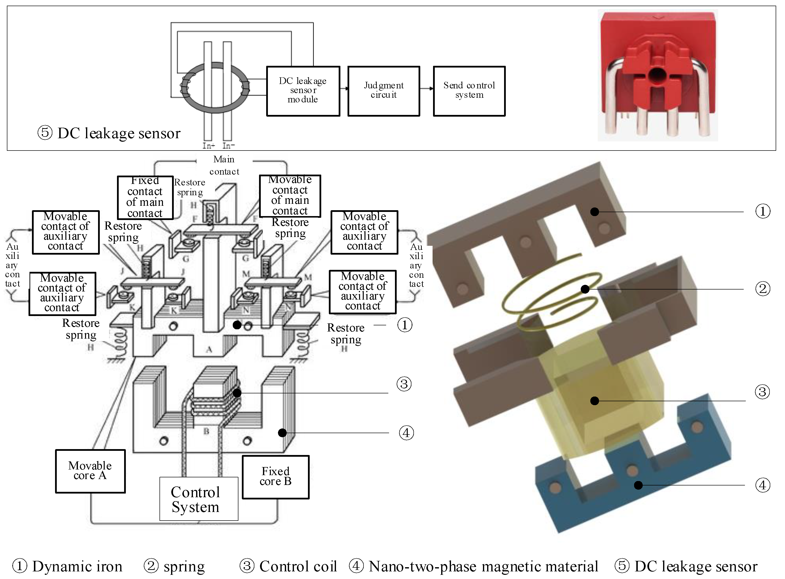
2. System Overview
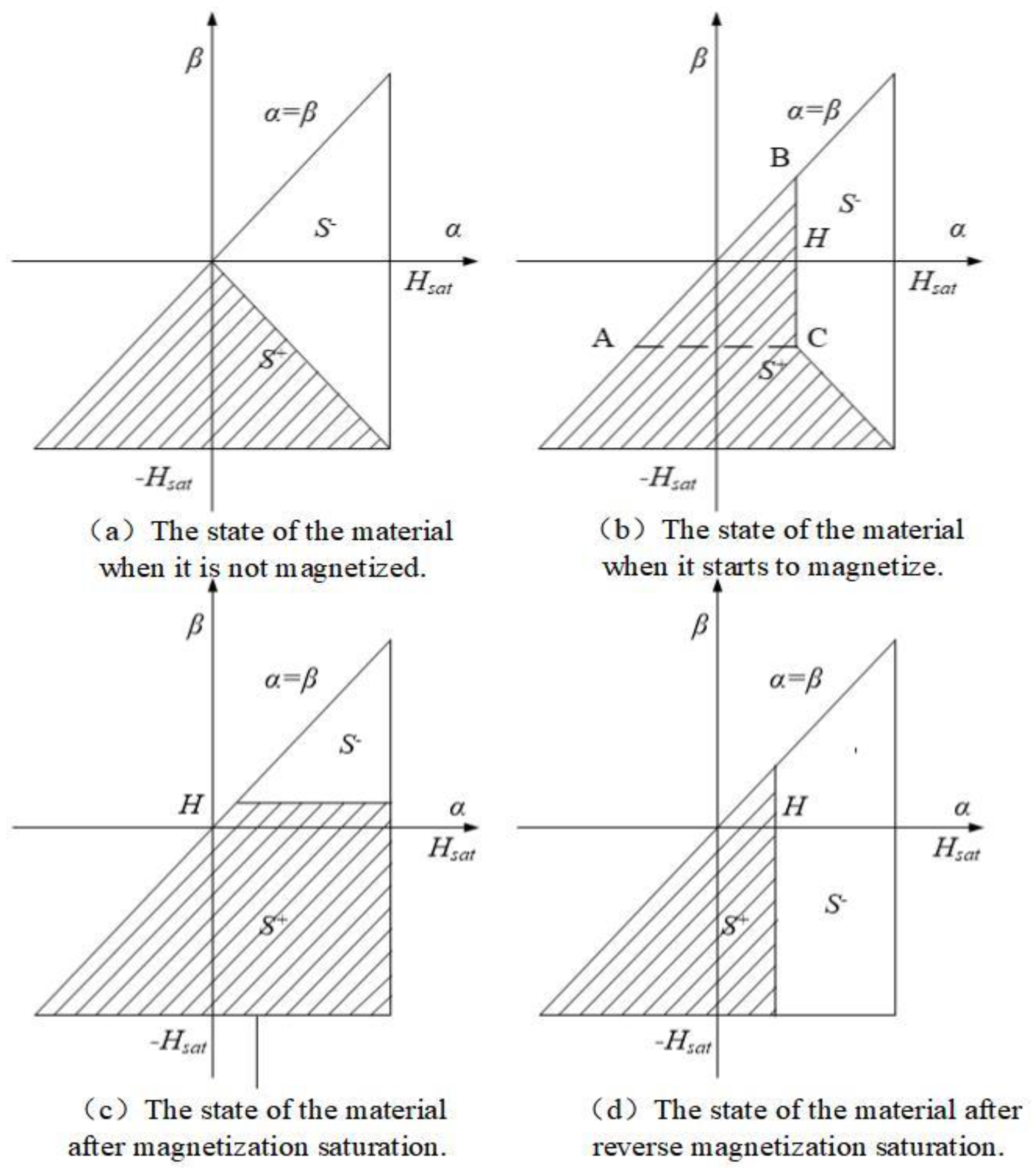
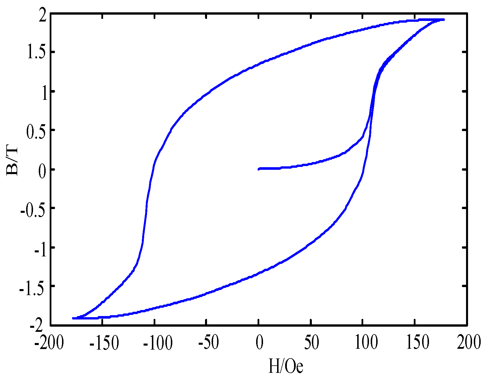
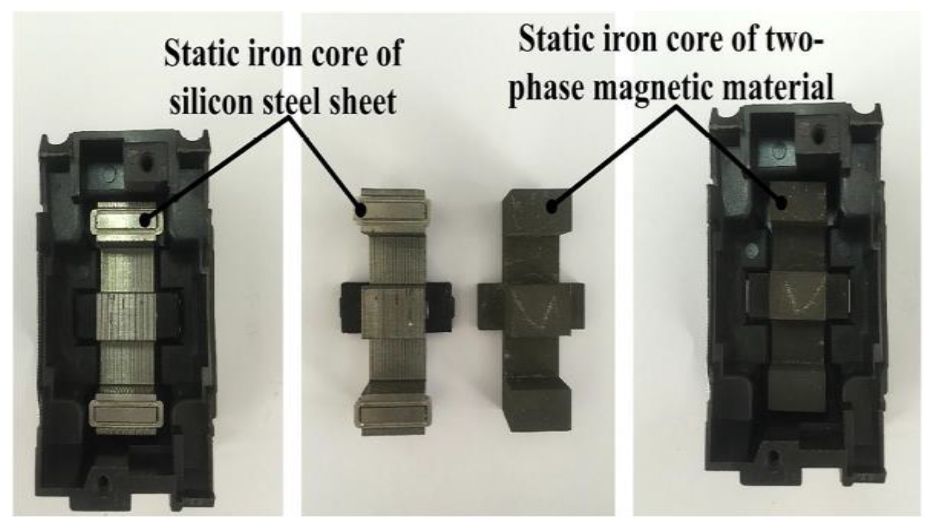
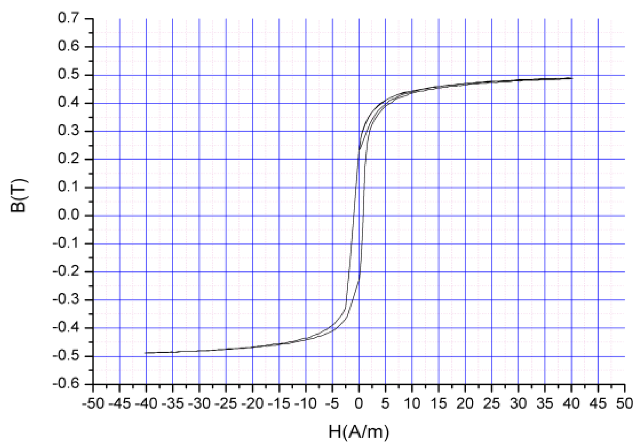
3. Characteristic Modeling and Preparation of Nano Two-Phase Magnetic Materials
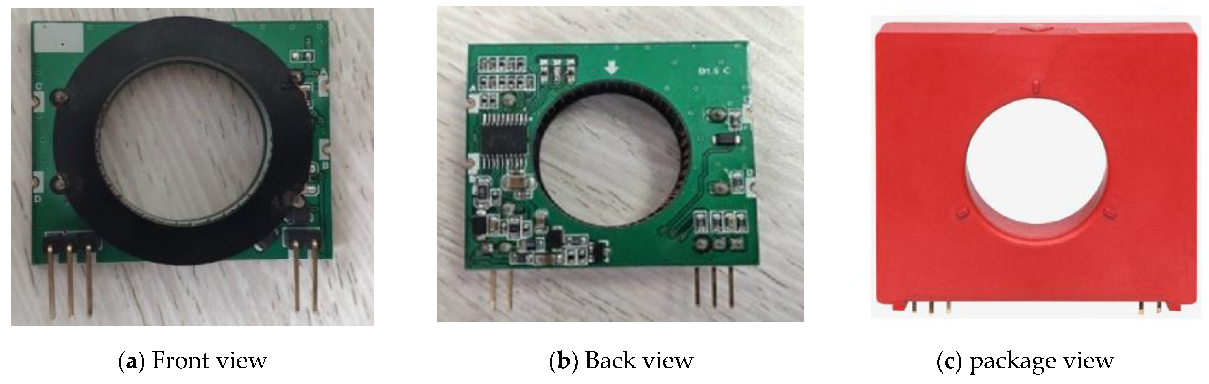
4. Design of DC Leakage Sensor
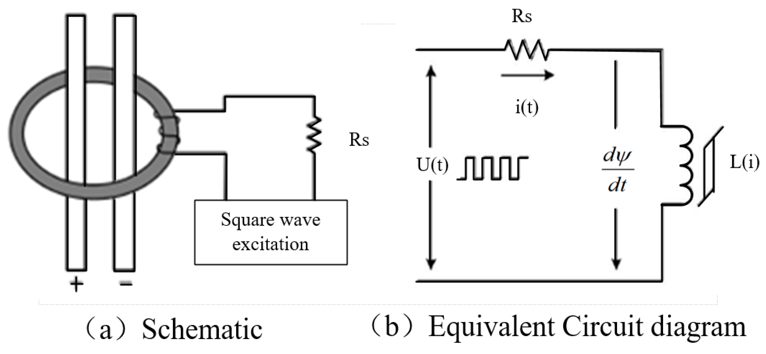
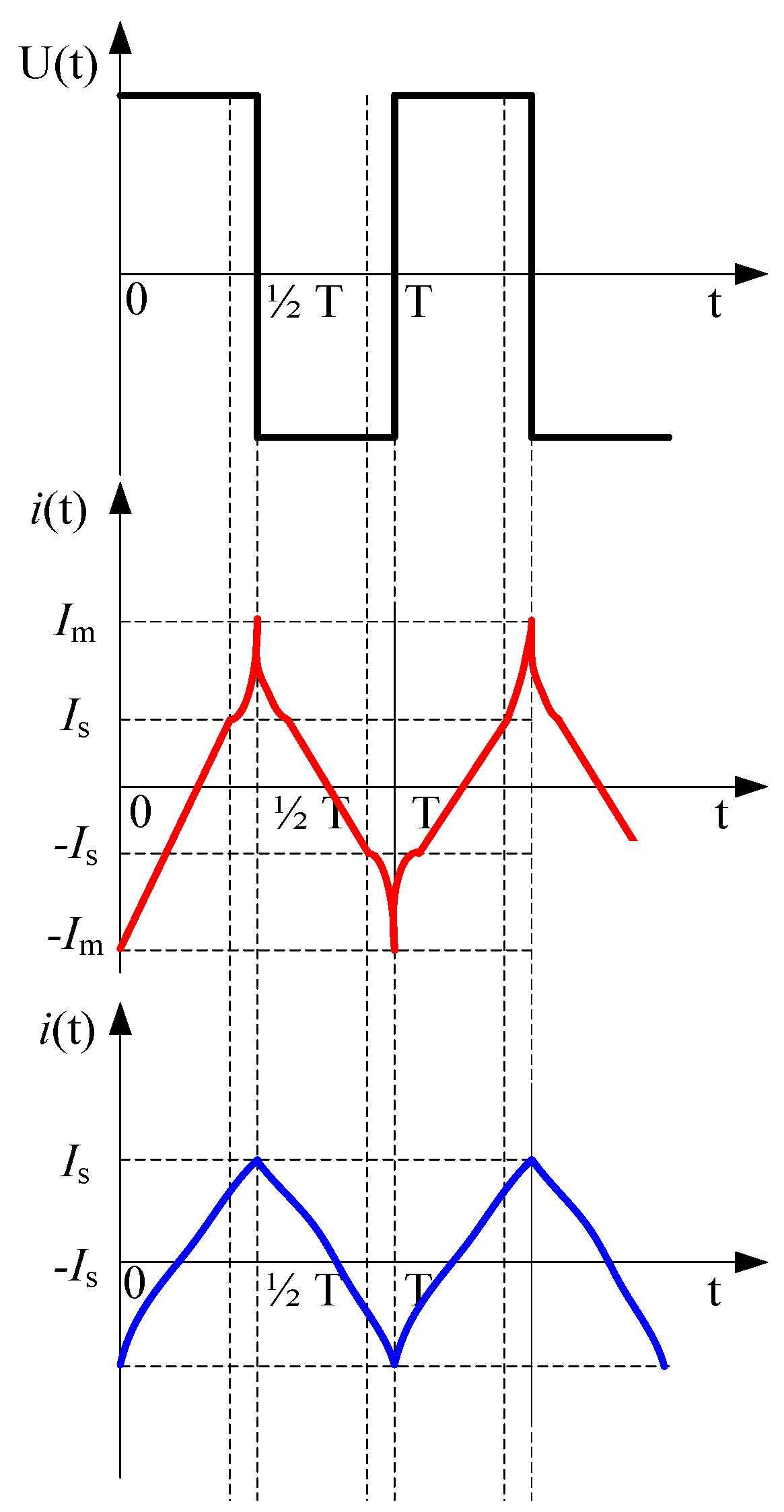
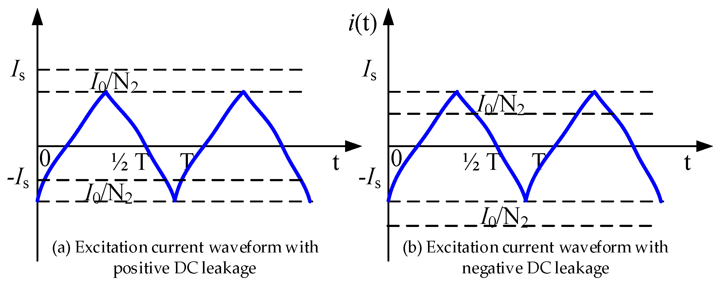
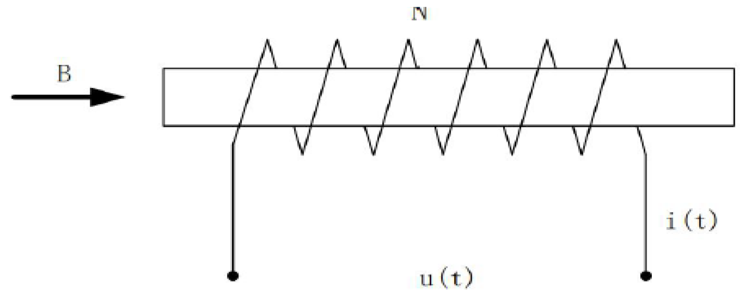
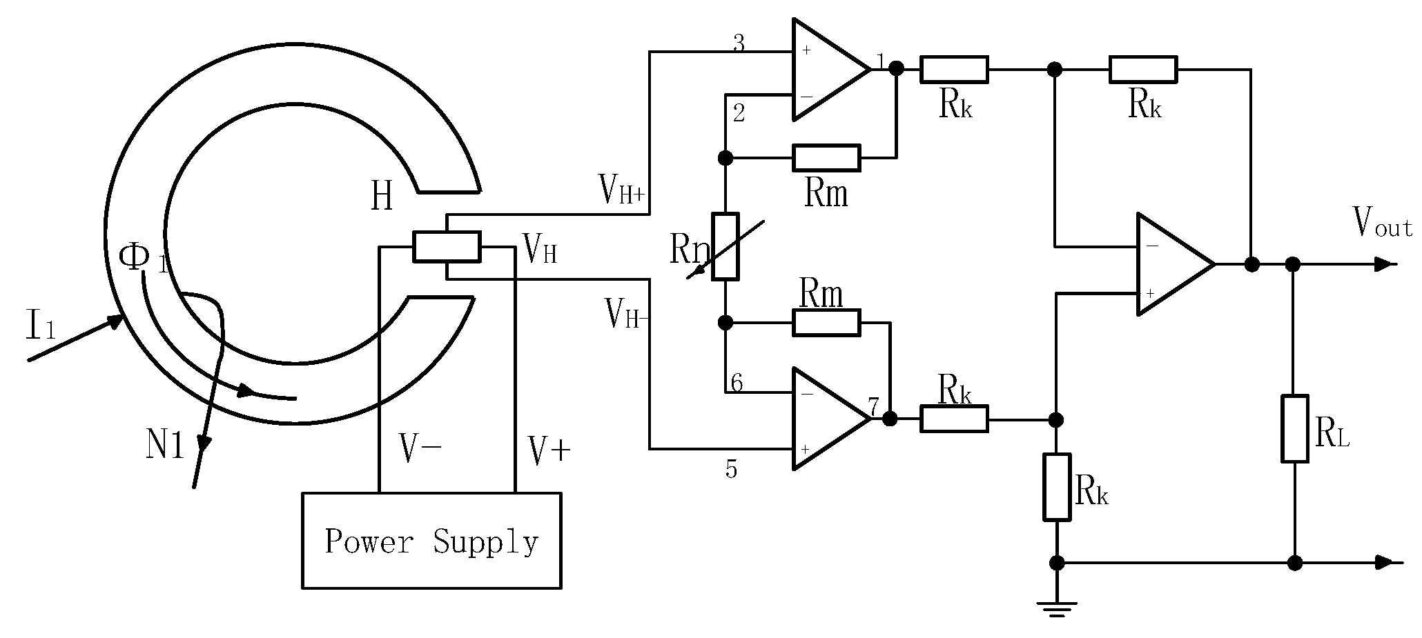
4.1. Leakage Current Detection of Single-Winding Single-Core Fluxgate
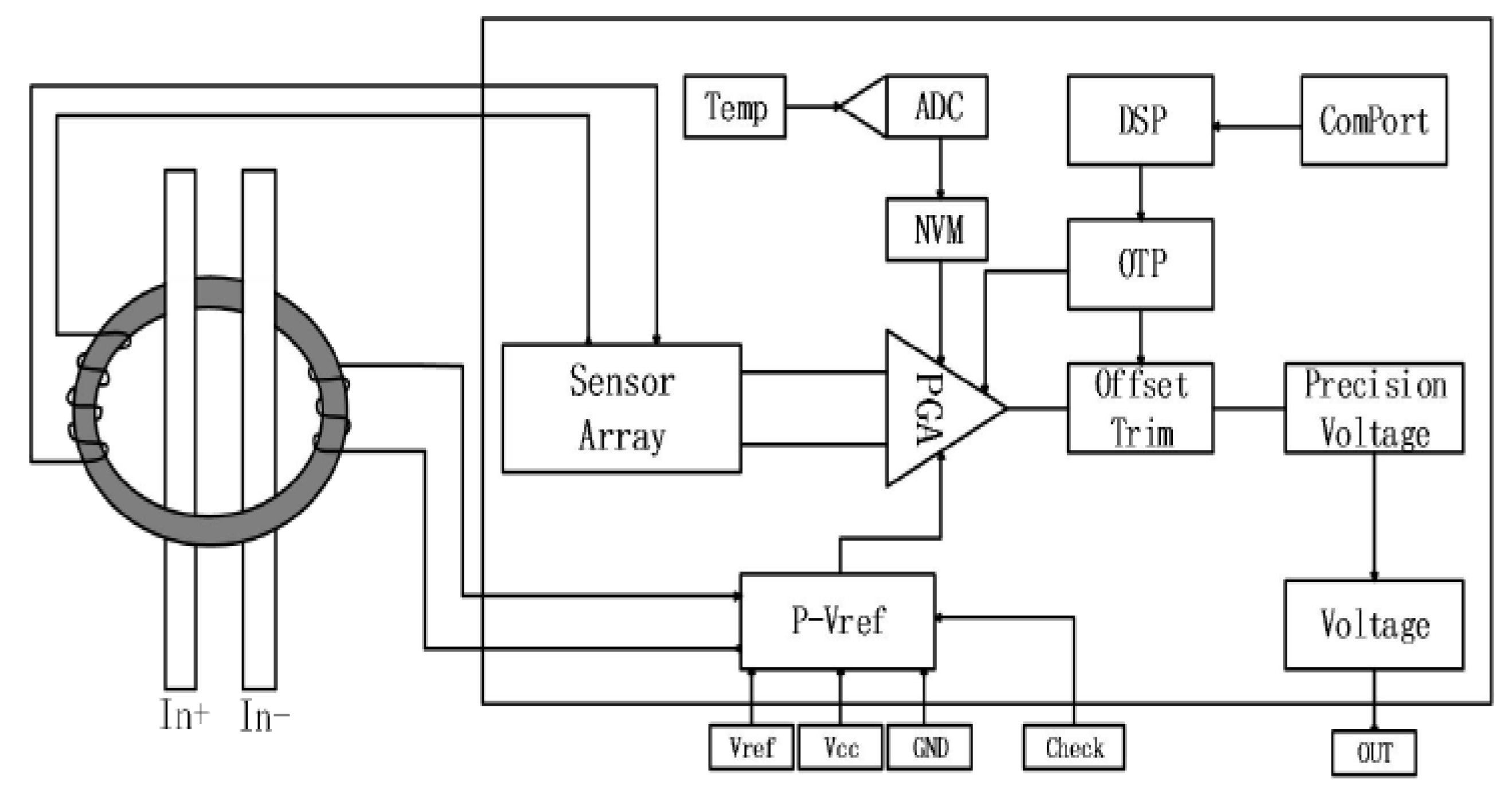
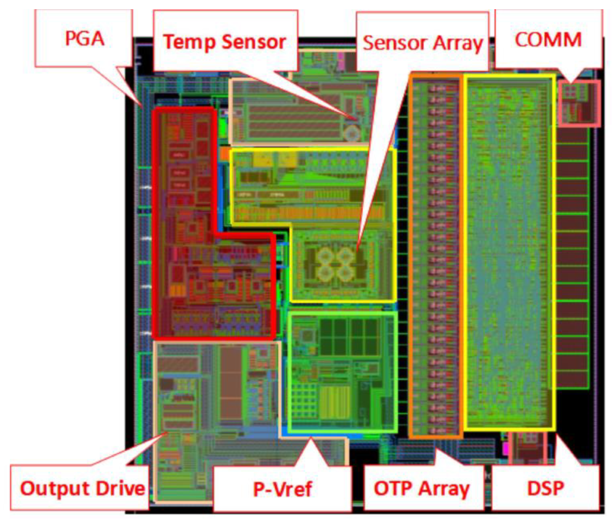
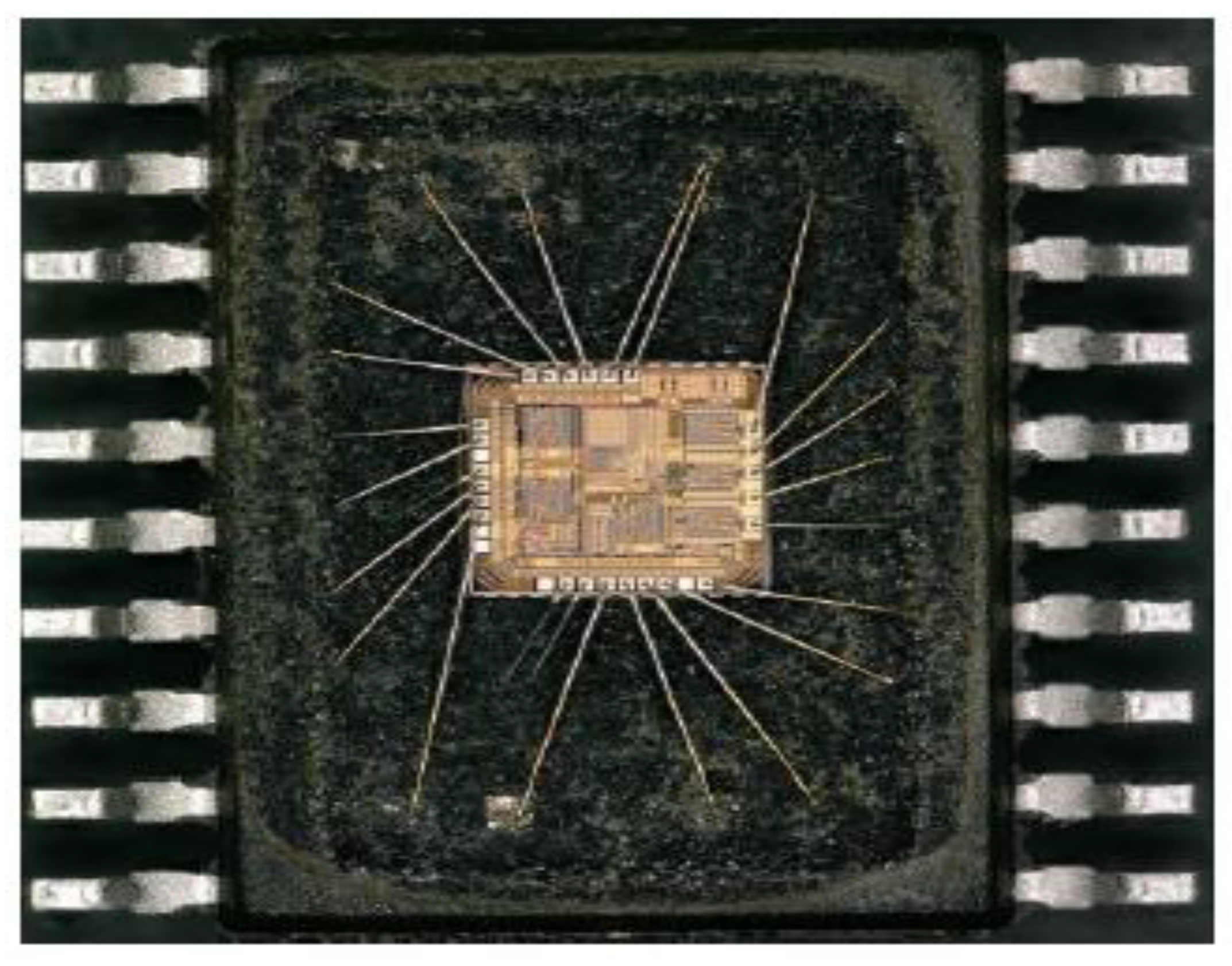
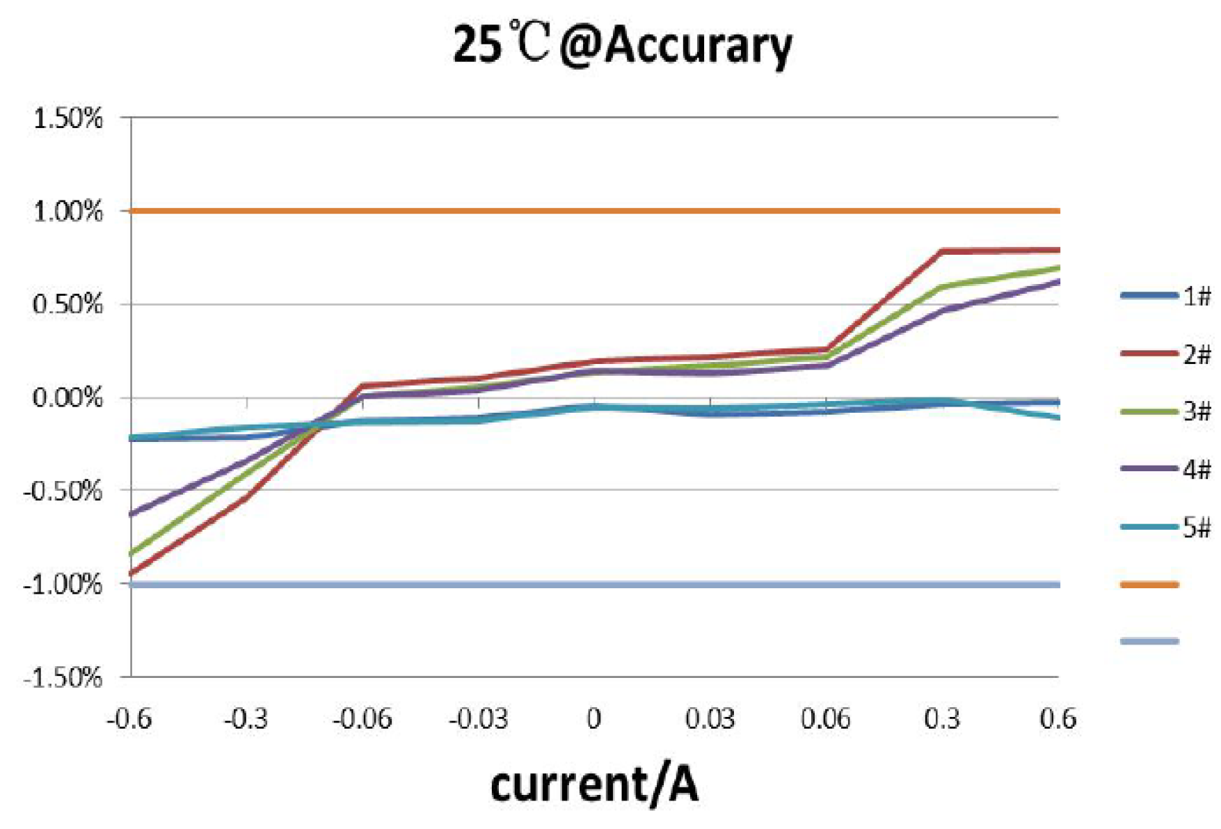
4.2. Chip Design
- (1)
- PGA: The programmable gain adjustment module, is used to adjust the sensor gain without manually adjusting the resistance, which can be modified by programming.
- (2)
- Temp sensor: Temperature compensation module, temperature calibration, used to compensate for the phenomenon of the leakage current.
- (3)
- Sensor Array: Sensing excitation detection arrays, generating excitation, while detecting signals after the magnetic core coupled.
- (4)
- COMM: Communication interface, read data onto external communication, and the program burning.
- (5)
- Output Drive: Output drivers, output drivers, increase the output current of the module, so that the sensor output is more stable.
- (6)
- P-Vref: Adjustable reference voltage output, programmable reference, adjustment reference voltage value (sensor V-ref is automatically adjusted, can be 2.5 V or 1.25 V, etc.).
- (7)
- OTP: Disposable programmable module.
- (8)
- DSP: Digital signal processor, arithmetic unit, its main application is real-time, quickly realize various digital signal processing algorithms.
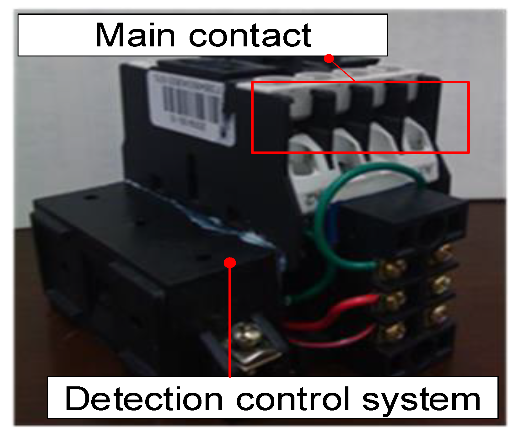
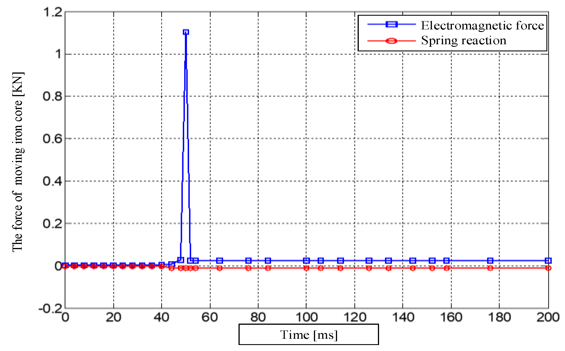
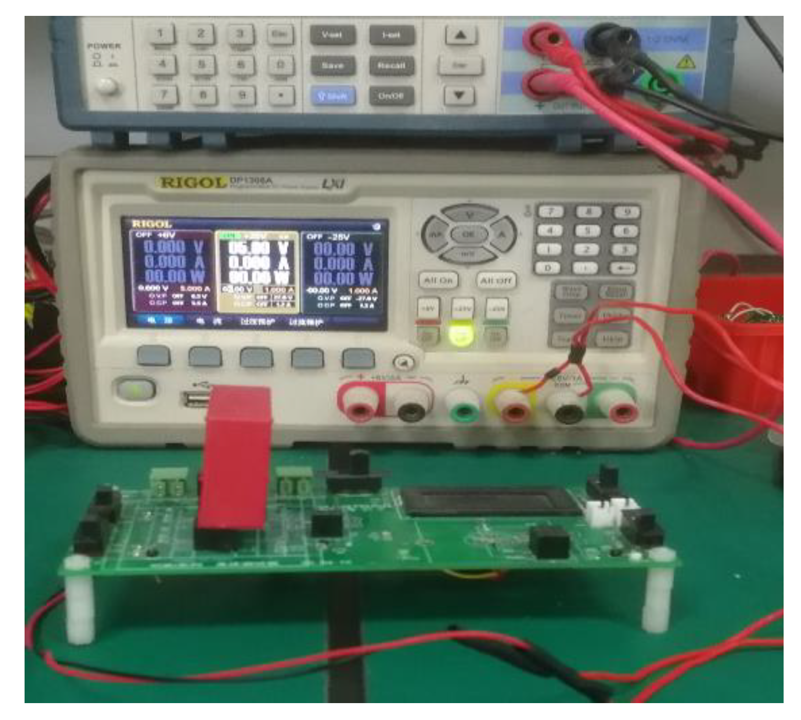
5. DC Leakage Protection Circuit Breaker Simulation and Experiment
6. Conclusions
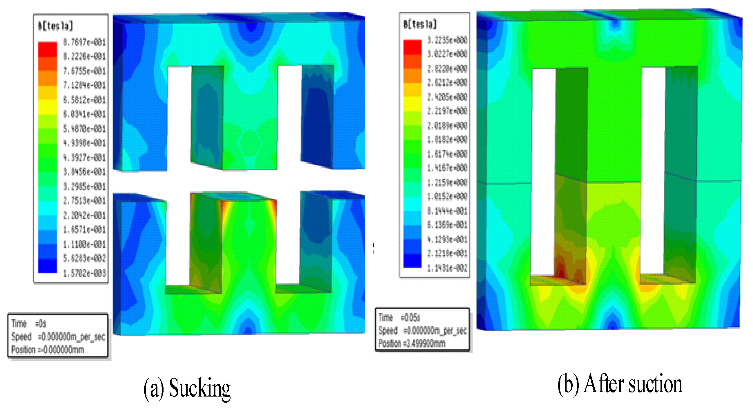
- (1)
- When the nano two-phase magnetic material is characterized by permanent magnetic characteristics, the magnetic induction intensity of the operating mechanism of intelligent/energy-saving DCCB leakage protection circuit breaker is 1.5 T, reaching a stable pull-in state.
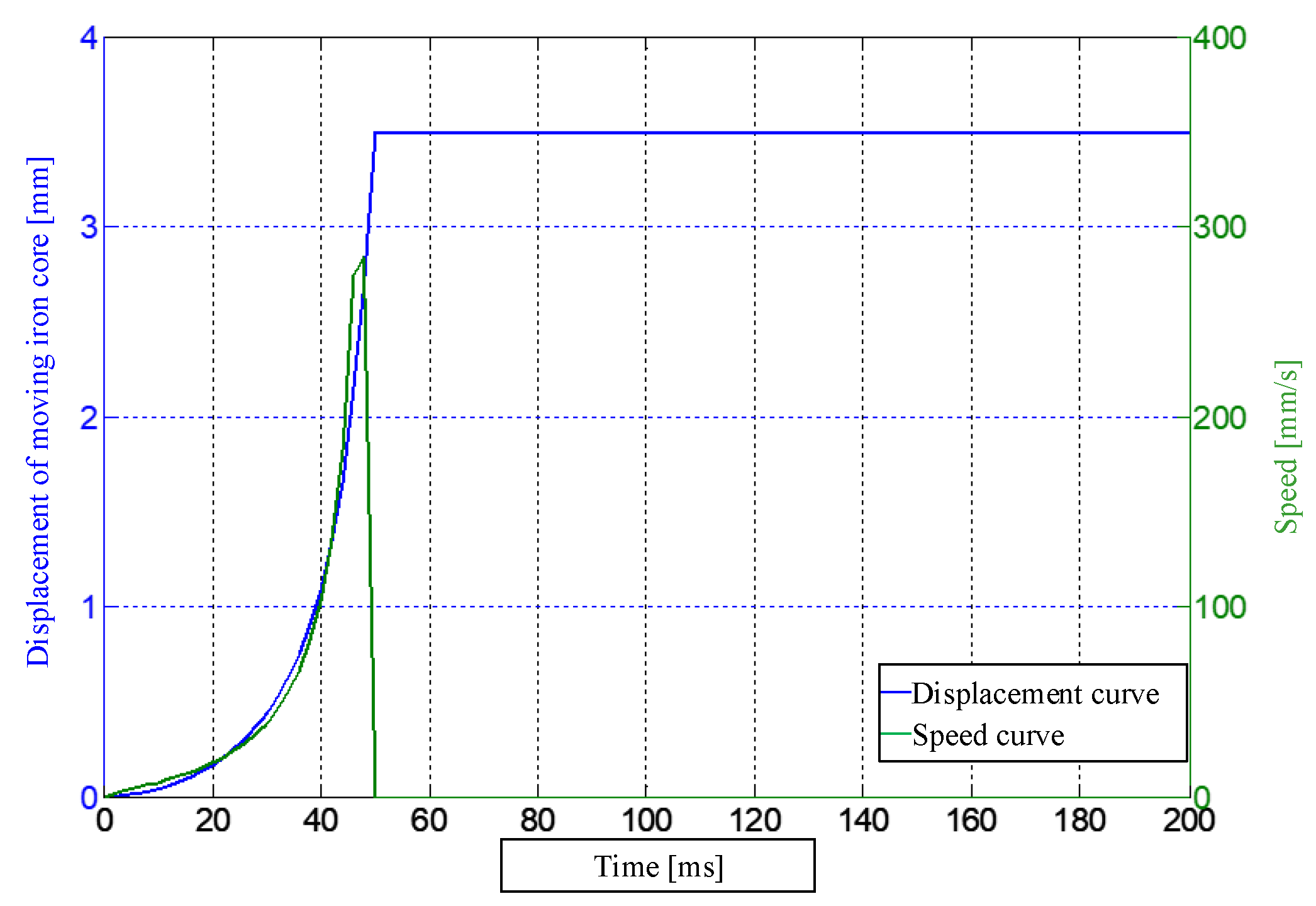
- (2)
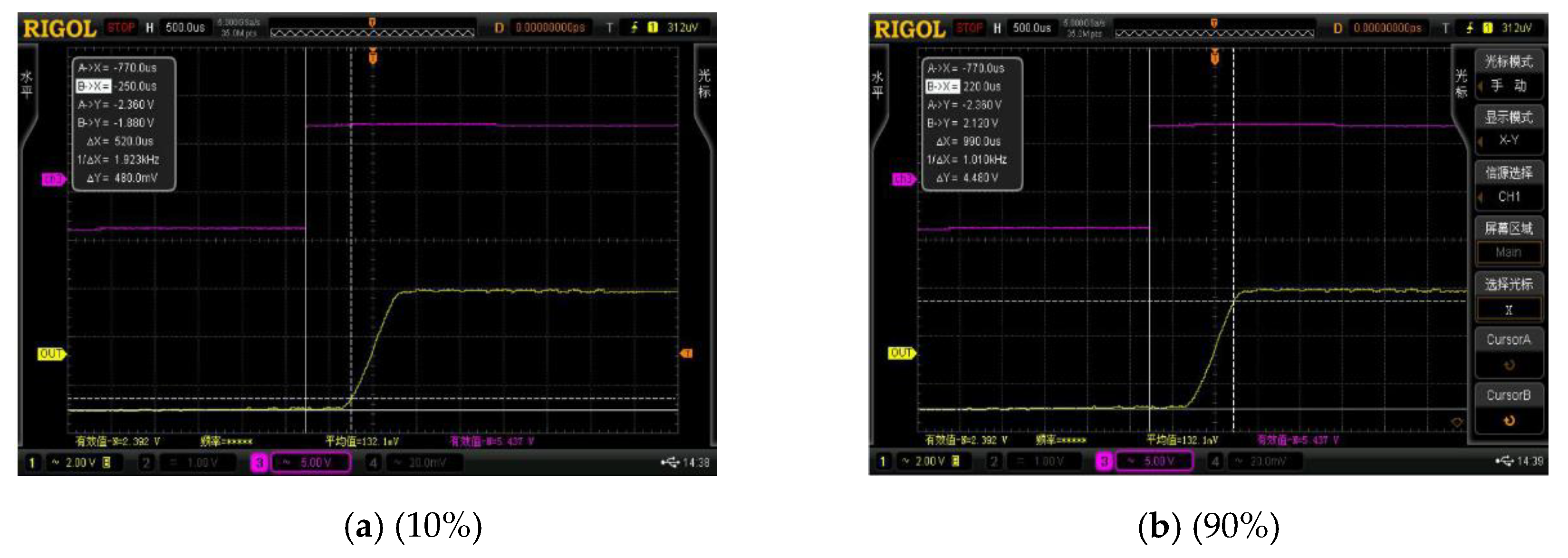
- When the DC leakage sensor reaches 10%, the response time is 520 μs and when it reaches 90%, the response time is 990 μs. Therefore, it can be judged that the equipment can make the leakage outlet mechanism act quickly to achieve the purpose of leakage protection.
- (3)
- The smooth implementation of this paper provides a new idea about the product development of energy-saving DCCB.
Author Contributions
Funding
Conflicts of Interest
References
- Xiao, J.; Wang, P.; Setyawan, L. Hierarchical Control of Hybrid Energy Storage System in DC Microgrids. IEEE Trans. Ind. Electron. 2015, 62, 4915–4924. [Google Scholar] [CrossRef]
- Haibo, L.; Yuming, Z.; Guowei, L.; Shiyong, J.; Zhengjia, Z. Energy efficiency comparison of AC and DC distribution systems in commercial buildings based on time series simulation. J. Electrotech. 2020, 35, 4194–4206. [Google Scholar]
- Liao, J.; Zhou, N.; Wang, Q.; Li, C.; Yang, J. Definition and correlation analysis of power quality indicators of DC distribution network. Chin. J. Electr. Eng. 2018, 38, 6847–6860+7119. [Google Scholar]
- Jung, J.H.; Kim, H.S.; Ryu, M.H.; Baek, J.W. Design methodology of bidirectional CLLC resonant converter for high-frequency isolation of DC distribution systems. IEEE Trans. Power Electron. 2013, 28, 1741–1755. [Google Scholar] [CrossRef]
- Gollee, R.; Gerlach, D. An FEM-Based Method for Analysis of the Dynamic Behavior of AC Contactors. IEEE Trans. Magn. 2000, 36, 1337–1340. [Google Scholar]
- Minfu, L.; Jinqiang, H.; Guowei, G.; Shanjun, W.; Xiongying, D. Development and research status of hybrid circuit breaker at home and abroad. High Volt. Eng. 2016, 42, 1688–1694. [Google Scholar]
- Shimin, X.; Chaochao, C.; Yi, J.; Jian, S.; Tao, W.; Jiali, H.; Ying, W. A Summary of Research on DC Distribution System Protection Technology. Proc. Chin. Soc. Electr. Eng. 2017, 37, 966–978. [Google Scholar]
- Luhui, L.; Zhihao, Y.; Lijun, F.; Youxing, X.; Nan, W. Research & Development Status and Prospects of Fast DC Circuit Breakers. Proc. Chin. Soc. Electr. Eng. 2017, 37, 966–978. [Google Scholar]
- Junjia, H.; Zhao, Y.; Wenting, Z.; Shai, F.; Xinlin, Y.; Huan, P. Summary of technology development of DC Breaker Technology. South Power Syst. Technol. 2015, 9, 9–15. [Google Scholar]
- Xiaoguang, W.; Bingjian, Y.; Guangfu, T. Technology Development and Engineering Practice of High Pressure DC Breaker Technology. Power Syst. Technol. 2017, 41, 1319–1323. [Google Scholar]
- Shede, P.; Mane, S. Leakage current sensing techniques. In Proceedings of the 2017 Third International Conference on Sensing, Signal Processing and Security (ICSSS), Chennai, India, 4–5 May 2017; pp. 181–185. [Google Scholar] [CrossRef]
- Kudo, T.; Kuribara, S.; Takahashi, Y. Wide-range ac/dc earth leakage current sensor using fluxgate with self-excitation system. In Proceedings of the SENSORS, 2011 IEEE, Limerick, Ireland, 28–31 October 2011; pp. 512–515. [Google Scholar] [CrossRef]
- Schade, E.; Shmelev, D.L. Numerical Simulation of High-Current Vacuum Arcs with an External Axial Magnetic Field. IEEE Trans. Plasma Sci. 2003, 31, 890–901. [Google Scholar] [CrossRef]
- Zheng, S.; Kheirollahi, R.; Pan, J.; Xue, L.; Wang, J.; Lu, F. DC Circuit Breakers: A Technology Development Status Survey. IEEE Trans. Smart Grid. 2021. [Google Scholar] [CrossRef]
- Watanabe, H.; Itoh, J.-I.; Koike, N.; Nagai, S. PV Micro-Inverter Topology Using LLC Resonant Converter. Energies 2019, 12, 3106. [Google Scholar] [CrossRef] [Green Version]
- Rezaei-Zare, A.; Iravani, R.; Sanaye-Pasand, M.; Mohseni, H.; Farhangi, S. An Accurate Current Transformer Model Based on Preisach Theory for the Analysis of Electromagnetic Transients. IEEE Trans. Power Deliv. 2008, 23, 233–242. [Google Scholar] [CrossRef]
- Nana, D.; Weijie, X.; Yongjian, L.; Shuhong, W.; Jianguo, Z. Simulation of Magnetic Properties of Soft Magnetic Composites Based on Limiting Hysteresis Loop Method. J. Electrotech. Technol. 2018, 33, 4739–4745. [Google Scholar] [CrossRef]
- Andreev, M.; Askarov, A.; Suvorov, A. Design of the magnetic hysteresis mathematical model based on Preisach theory. Electr. Eng. 2019, 101, 3–9. [Google Scholar] [CrossRef]
- Changxi, Y.; Qiong, X.; Xue, L.; Huan, W.; Kai, Z.; Hao, L. Zero-flux AC and DC current sensor based on fluxgate principle. Electr. Meas. Instrum. 2017, 54, 73–77. [Google Scholar]


| Temperature Range/°C | Current Range/A | Voltage Range/A | Measured Current/A | Sample 1 /V | Sample 2 /V | Sample 3 /V | Sample 4 /V | Sample 5 /V |
|---|---|---|---|---|---|---|---|---|
| 25 | 0.03 | 2.6 | 0.03004 | 2.5964 | 2.6087 | 2.6069 | 2.6051 | 2.5977 |
| 25 | 0.06 | 2.7 | 0.0599 | 2.6969 | 2.7105 | 2.7088 | 2.7067 | 2.6985 |
| 25 | 0.3 | 3.5 | 0.29972 | 3.4987 | 3.5313 | 3.5238 | 3.5185 | 3.4994 |
| 25 | 0.6 | 4.5 | 0.59967 | 4.4989 | 4.5317 | 4.5278 | 4.5247 | 4.4994 |
| 25 | 0 | 2.5 | 0 | 2.4982 | 2.5079 | 2.5054 | 2.5058 | 2.4979 |
| 25 | −0.03 | 2.4 | −0.03003 | 2.3955 | 2.404 | 2.4023 | 2.4015 | 2.3951 |
| 25 | −0.03 | 2.3 | −0.0599 | 2.2949 | 2.3024 | 2.3003 | 2.3001 | 2.2947 |
| 25 | −0.3 | 1.5 | −0.29974 | 1.4915 | 1.4786 | 1.4837 | 1.4865 | 1.4935 |
| 25 | −0.6 | 0.5 | −0.59969 | 0.4909 | 0.4623 | 0.4665 | 0.475 | 0.4913 |
Publisher’s Note: MDPI stays neutral with regard to jurisdictional claims in published maps and institutional affiliations. |
© 2022 by the authors. Licensee MDPI, Basel, Switzerland. This article is an open access article distributed under the terms and conditions of the Creative Commons Attribution (CC BY) license (https://creativecommons.org/licenses/by/4.0/).
Share and Cite
Hou, L.; Chen, D.; Li, T.; Zhao, M.; Ren, H. Design and Research on DC Electric Leakage Protection Circuit Breaker. Energies 2022, 15, 5605. https://doi.org/10.3390/en15155605
Hou L, Chen D, Li T, Zhao M, Ren H. Design and Research on DC Electric Leakage Protection Circuit Breaker. Energies. 2022; 15(15):5605. https://doi.org/10.3390/en15155605
Chicago/Turabian StyleHou, Lei, Dezhi Chen, Tongfei Li, Ming Zhao, and Huaibo Ren. 2022. "Design and Research on DC Electric Leakage Protection Circuit Breaker" Energies 15, no. 15: 5605. https://doi.org/10.3390/en15155605