1. Introduction
The increasing attention towards IPMSMs over the last decades is justified by the fact that this type of machine provides several advantages if compared with motors of the traditional type. Indeed, higher efficiency, reliability, power factor, torque/weight and power/current ratios can be obtained thanks to the adoption of high-energy rare-earth PMs of either the SmCo-type or the NdFeB-type, which has significantly improved the performance in several commercial and industrial applications. However, one of the main drawbacks of IPMSM is torque pulsation [
1,
2], which can be generated from various causes [
3,
4] and which is composed of the ripple torque, determined by the interaction between the PMs flux density and the space harmonics generated by the stator currents, and the cogging torque, caused by the interaction between the rotor PMs and the stator teeth. The cogging torque phenomenon determines a reduction in the IPMSM performance, generating vibrations, acoustic disturbances and mechanical stress [
2]. The recent scientific literature proposes several procedures for the minimization of the cogging torque produced by permanent magnet machines [
5,
6,
7,
8,
9,
10,
11,
12,
13,
14,
15,
16,
17,
18,
19,
20,
21,
22,
23,
24,
25,
26,
27,
28,
29,
30,
31,
32,
33,
34,
35,
36,
37,
38,
39,
40,
41,
42,
43,
44,
45], which can be classified into two big areas: design techniques and control techniques. The first ones are finalized to optimize the geometry of either the stator or rotor of the electric machine, taking into account the reduction of the magnetic energy variations during the rotor rotation, leading to significant mitigation of the torque pulsations. An overview of the most commonly adopted techniques concerning this category is given in
Section 2. On the other hand, the second category consists of injecting online current harmonics to intentionally generate additional high-frequency torque components, whose profiles are accurately designed to completely compensate for the cogging torque components detected in the related control system [
46,
47,
48,
49,
50]. In any case, it can be stated that many techniques for cogging torque suppression present the drawback of being either expensive or complex in terms of the PMSM design stage [
34,
38]. In this context, the authors propose a simple cogging torque minimization procedure, consisting of a progressive modification of the basic geometrical structure of the IPMSM rotor lamination. As demonstrated in this paper, the procedure can be generalized for the main topologies of PMSM, independently from the number of stator slots or the location of the permanent magnets. In addition, by simply acting on the shape of the rotor lamination and by choosing the optimized pattern, the cogging torque components can be theoretically canceled, avoiding the adoption of expensive pole skewing techniques or other more complex methods previously reported. Among the techniques described in the scientific literature, this paper proposes a relatively simple cogging torque minimization procedure, and the structure of this work is given below:
Section 2 proposes an overview of the main design techniques for cogging torque minimization described in the most recent literature.
Section 3 provides a brief analytical description of the cogging torque phenomenon.
Section 4 describes the basic IPMSM model and reports the related FEM analysis and the cogging torque computation carried out from this model.
Section 5 deals with the procedure of the rotor lamination modification of the basic IPMSM model, obtaining 13 other IPMSM structures. For each of the proposed models, FEM analysis and cogging torque computation are performed.
Section 6 is focused on comparing the cogging torque between the IPMSM models and the results are analyzed and discussed.
Section 7 reports the second example of IPMSM structure, obtaining similar promising results obtained for the first IPMSM model.
2. An Overview of the Cogging Torque Minimization Techniques
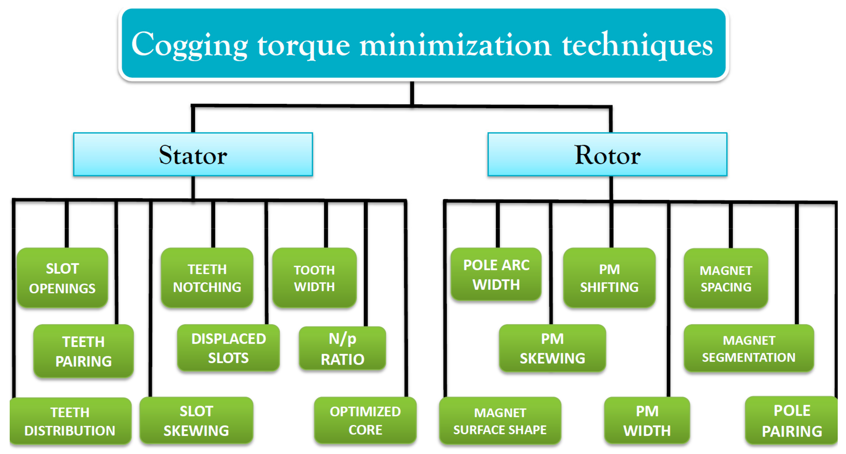
Figure 1 gives an overview of the main cogging torque minimization techniques presented in the recent literature and adopted for both axial-flux and radial-flux PMSMs.
Some of these techniques involve the optimum design of stator elements, such as, for example, the skewing of the lamination stack [
5,
6], or the modification of the stator tooth width [
7]. The cogging torque can also be minimized by acting on the pole arc width, as described in [
8,
9]. An interesting alternative to the latest technique is proposed in [
10,
11], where the cogging torque is reduced by determining not only an adequate width of the polar arc, but also an optimized shape. Wanjiku et al. [
12] demonstrated that, by acting on the slot-opening width, the cogging torque can be significantly mitigated. As referred to in
Figure 1, the cogging torque can also be reduced by acting on the ratio between stator slot number
N and stator pole pairs
p [
13], or by the so-called axial pole pairing [
14], or the axial pole shaping [
15]. Other techniques involve the optimization of the ratio between stator and rotor poles [
16] or the adequate design of the stator core [
17,
18]. Teeth notching can be also a valid technique for the cogging torque reduction, as stated by Zhao [
19], Koh [
20] and Zhou [
21]. Interesting techniques have been proposed in [
22], where the cogging torque effects are minimized by adopting shifted stator teeth with different widths, and in [
13], in which a non-uniform stator teeth distribution is adopted to reduce the cogging torque effects.
Concerning the rotor side modification for the cogging torque minimization, one of the most adopted techniques is magnet skewing [
24,
25]. M. Lukaniszyn et al. proposed a method based on the optimization of the PM skew angle by developing a genetic algorithm [
26], and Jiang improved that work by comparing and minimizing the cogging torque effects on different types of rotor skew patterns by employing his genetic algorithm [
27]. Another recently used technique is rotor teeth notching [
28,
29], whereas Wang et al. [
30] proposed a new method based on the adequate selection of PMs with different widths, whereas other researchers have also verified the influence of the surface shape of the PMs [
31,
32]. The cogging torque effect can be also minimized by adequately shifting the PMs, as presented in [
33], or by choosing an adequate PM spacing, according to [
34]. As demonstrated in [
35], one of the most effective and low-cost approaches is magnet skewing. Based on the latest method, Zhao presented a procedure consisting of a sinusoidal shaping of the permanent magnets located inside the rotor structure, obtaining comparable results to those achieved with the skewing technique [
36]. As for the rotor lamination, Kim proposed a method for reducing the cogging torque by acting on an asymmetrical lamination of the rotor core [
37].
As stated in [
51], the feasibility of these cogging torque reduction procedures is strictly related to the manufacturability of the electrical motor, which can be subjected to relevant manufacturing tolerances. For instance, the accuracy in magnet shape and position is a crucial issue to ensure the cogging torque minimization; possible irregularities due to assembly tolerances or width variations can compromise the effectiveness of the minimization techniques [
52]. In terms of global optimization of the motor, slot opening optimization and stator skewing can be assumed as the best solutions; however, these techniques are subject to relevant manufacturing costs.
3. The Cogging Torque Phenomenon
The cogging torque, which represents one of the main components of torque pulsation in IPMSMs, is determined by the interaction between the stator teeth and the permanent magnets located in the rotor structure. Typically, this phenomenon is independent of the stator currents, even if, in the case of saturated teeth, the cogging torque is increased due to the wider slot openings. This phenomenon can be analytically examined by considering the variation of the magnetic energy
Wms stored in the air-gap caused by the alternation between slots and teeth:
where
φ is the angular position of the rotor. By defining
as the magnetic permeability of air and
Bm as the magnetic flux density,
Wms can be expressed as follows:
where
Bm is dependent on the magnetic permeance
Pm, which varies with the position of the slot openings to
φ, and the magnetomotive force (MMF)
produced by the permanent magnets:
By expressing the magnetic flux density and the permeance distributions in terms of the Fourier series, the cogging torque can be computed through the following general formula [
1,
6]:
where
La is the axial length of the machine,
R1 and
R2 are the outer and inner stator radii, respectively, and
t is the least common multiple between
N and
p.
Therefore, it can be stated that the cogging torque is dependent on several geometrical parameters of both stator and rotor structures. For instance, an adequate selection of the slots-poles ratio is crucial to minimize the cogging torque, which can be characterized by the following parameter
cT:
In addition, the skew factor
ksk and the optimal ratio between rotor pole arc and width, namely
βopt, represent very sensitive parameters for the cogging torque reduction [
38,
39]. These quantities are given, respectively, by:
And
where the values of the parameters (such as
and
) reported in (6) and (7) depend on the machine geometry, such as air-gap length, magnet shape, pole arc, pole width, rotor lamination shape and
N/p ratio.
From this perspective, it appears clear that the cogging torque can be significantly reduced by adequately selecting the optimal geometry of the iron lamination pack, as demonstrated in the next sections.
4. Basic IPMSM Structure and FEM Analysis
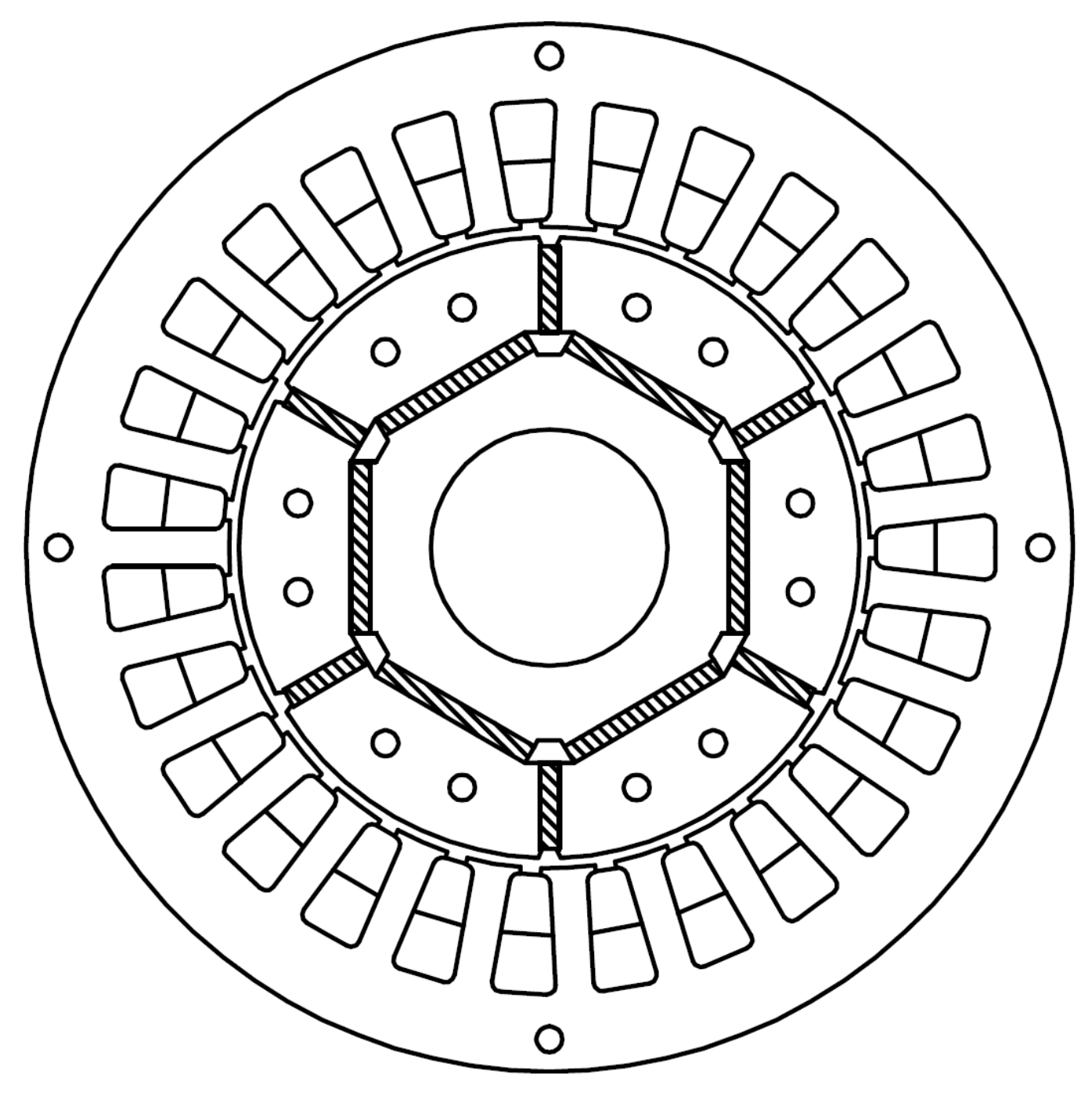
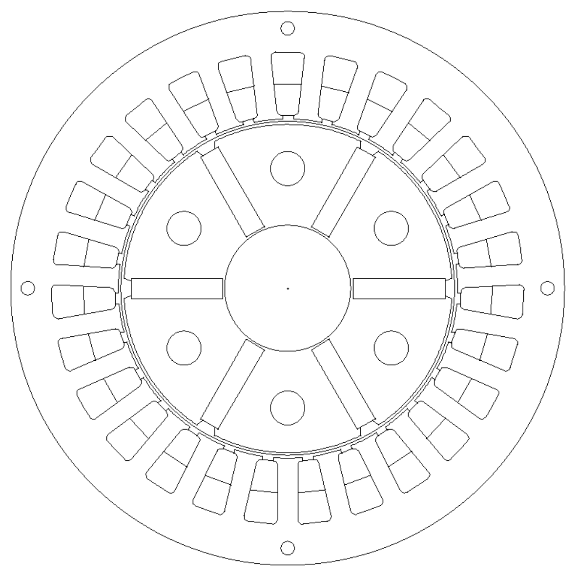
Figure 2 shows the basic geometry of the IPMSM considered for this study. This structure is derived from a commercial motor, whose rated values are summarized in
Table 1 and whose geometrical parameters are reported in
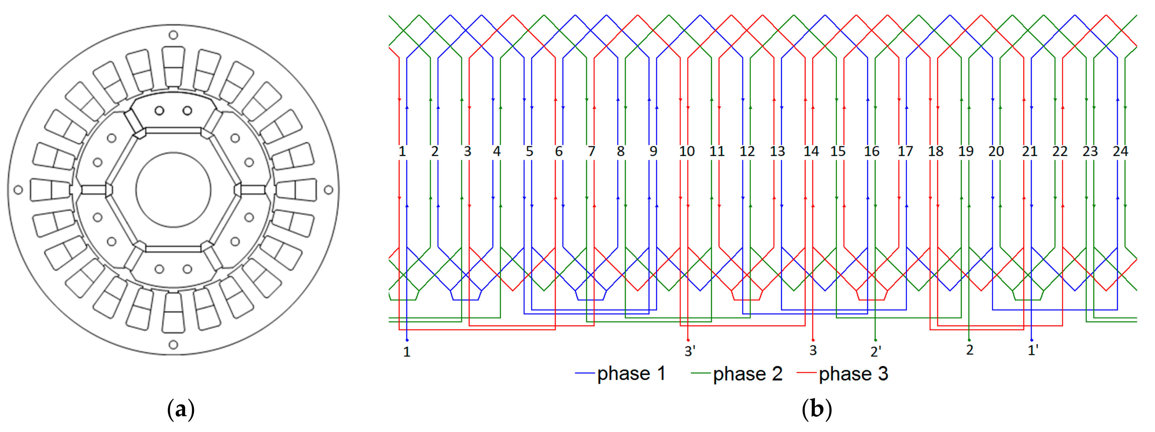
Table 2. It is a fractional power, six-pole, brushless machine with 27 stator slots and 12 NdFeB permanent magnets located inside the rotor. As shown by the Figure, the disposition of the PMs is designed to produce a magnetic flux both in the radial and the tangential directions. The generated torque is equal to 1.8 Nm at 4000 rpm with a voltage supply of 132 V.
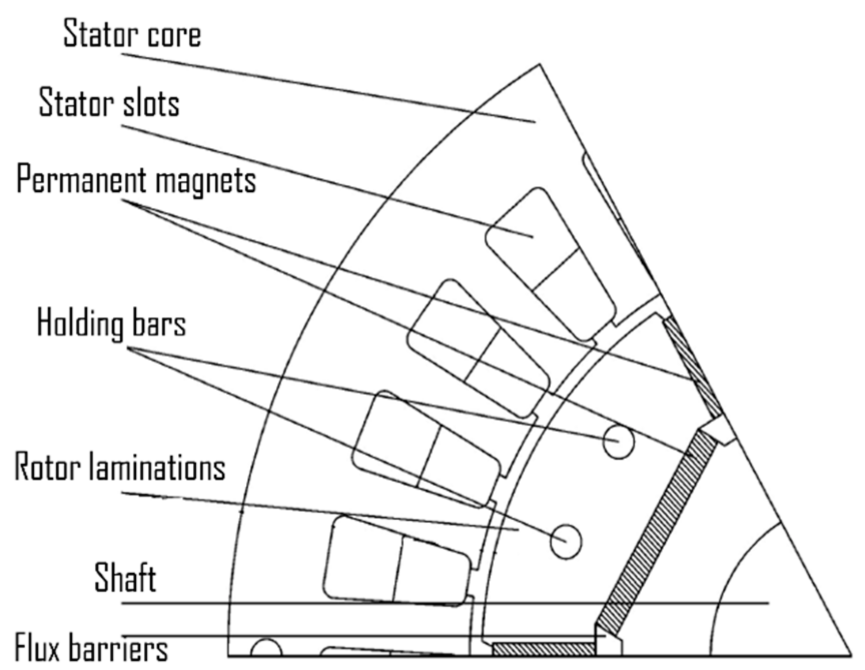
By referring to one pole sector,
Figure 3 shows a representation of the geometrical parameters of the machine. The iron laminations of the M350-50A type have been considered for both stator and rotor cores, which are spaced by a 0.8 mm air gap, whereas the axial length of the IPMSM is equal to 59 mm.
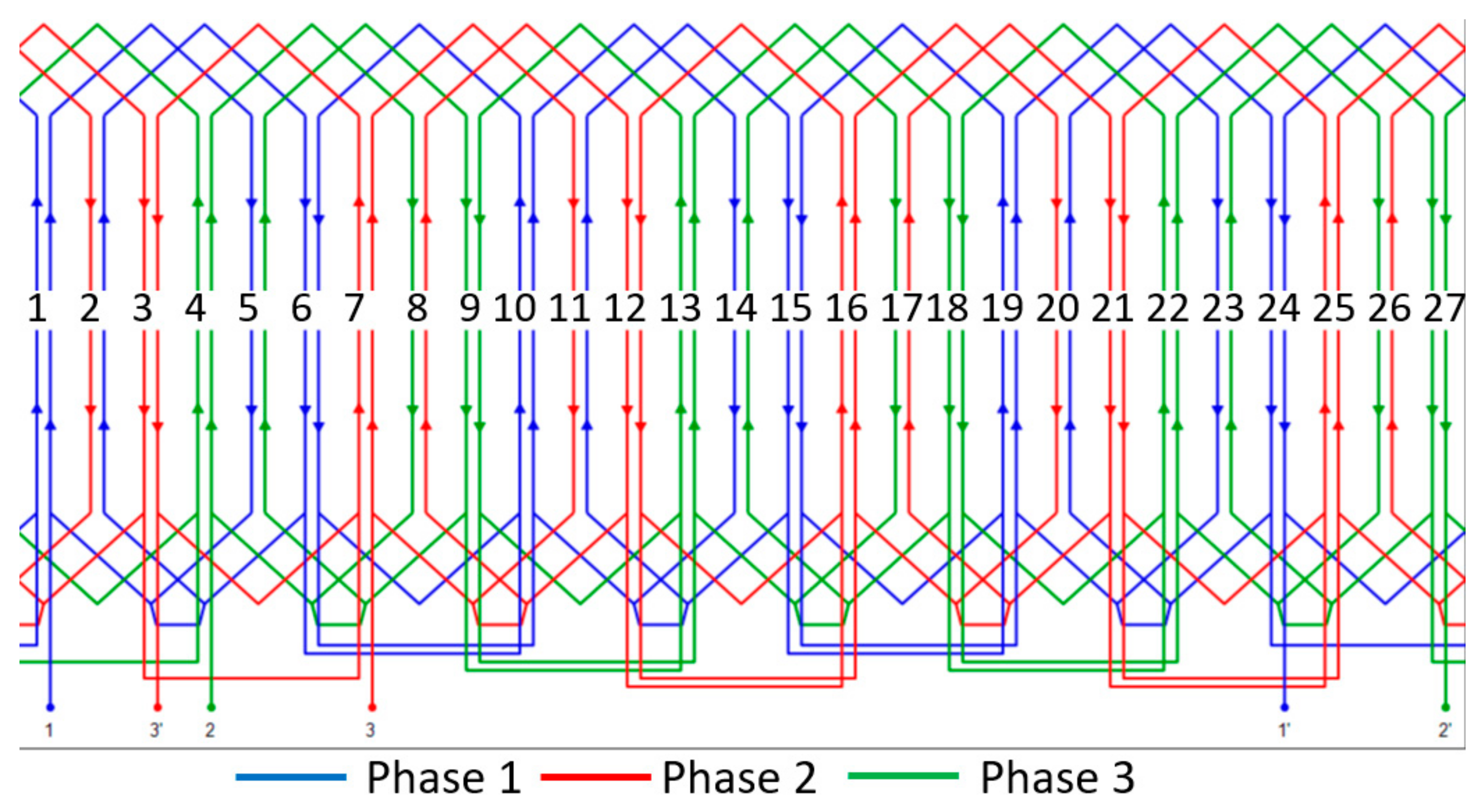
The three-phase winding chosen for the motor is distributed through the 27 slots in a double-layer, star configuration with 3 pole pairs, as depicted in
Figure 4. The plane scheme of the winding clearly shows that it is composed of three repetitions of a base winding located in nine slots per pole pair [
40,
41]. Moreover, the coil pitch is equal to 4, leading to a shortened pitch configuration of the winding, so that the 5th and 7th order MMF harmonics can be significantly reduced. It can also be noted that the end connections are arranged with groups of 1 or 2 coils for each phase, and the number of slots per pole per phase is equal to 1 + 1/2, which gives a fractional slot configuration of the winding. The general design guidelines used in this work can be found in [
53,
54,
55].
Among the relevant number of approaches adopted by the scientific community to study the phenomenon of cogging torque, from FEM to analytical models [
42,
43,
44,
45], the cogging torque effects are here analyzed by using a FEM approach. This method is mainly composed of three phases:
pre-processing, which consists in designing the geometry of the machine, selecting the type of materials and assigning the boundary conditions.
solution, consisting of the determination of the FEM solution of the problem.
post-processing, which processes the solutions in terms of scalar or vector quantities.
By employing this analysis, the behavior of the main electrical quantities involved in the system has been computed, such as the flux density field plot, the spatial distribution of both the tangential and the radial components of the flux density (namely Bt and Bn, respectively) as a function of the coordinate x (measured on the circumference passing through the middle of the air-gap), the average value of the pole flux, the cogging torque as a function of the angular position of the rotor and the related harmonic content.
The determination of the cogging torque values has been achieved through several finite element simulations for different angular positions of the IPMSM rotor and without any driving supply. In more detail, the rotor position
δ has been varied from 0° to 360° with steps of 0.2°; therefore, the performance in terms of cogging torque and magnetic flux density has been evaluated for several angular rotor positions, obtaining 1800 rotor positions for the specific model and, consequently, 1800 overall FEM simulations for each of the proposed models (actually, the cogging torque distribution could be obtained just for 6.66/0.2
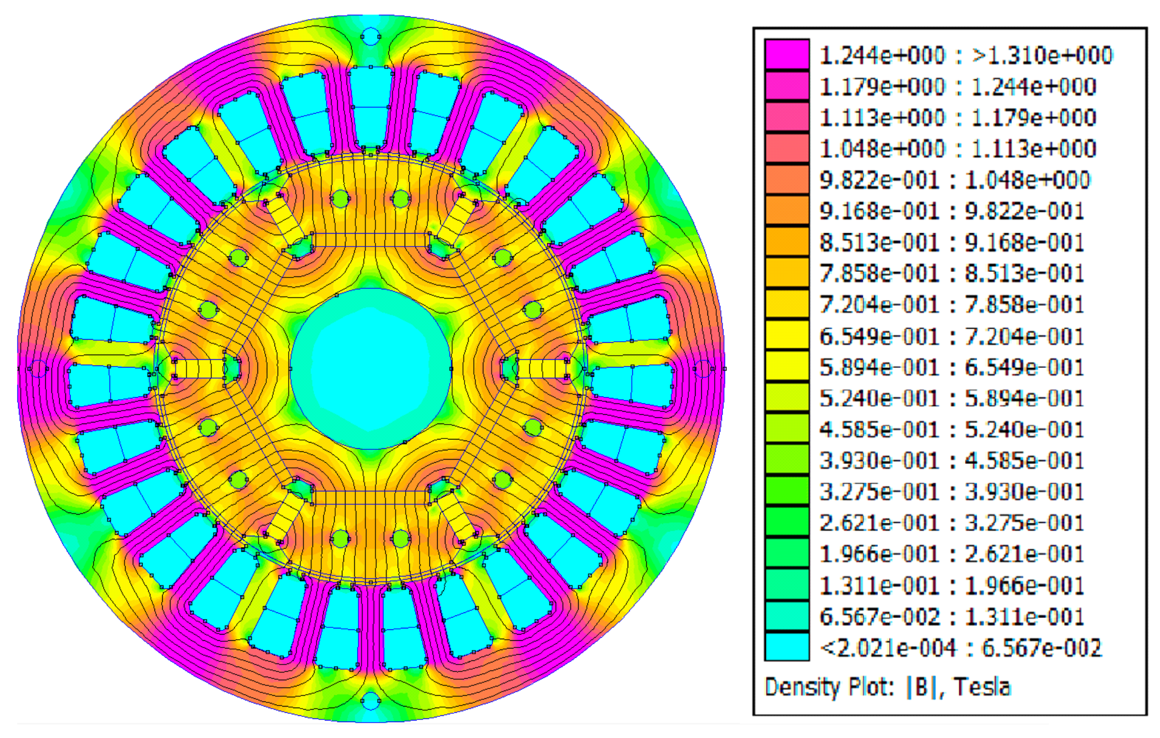
34 simulations of each model). For instance, the plot of the flux density field at δ = 0 is reported in
Figure 5. As expected, the density plot and the distribution of the flux lines show that the areas subjected to the highest fields are located in the stator teeth and some sections of the stator core. As shown by the
legenda, the values of the flux density field range up to 1.2 T along the stator yoke and 0.6 T in the air gap. The Dirichlet boundary conditions have been chosen with the value of potential
A = 0. Moreover, a steady-state simulation of the magnetic field with no current has been performed for the entire cross-section of all the proposed models. The adopted software allows the automatic creation of the mesh (for the basic model, a mesh with 115,834 nodes was created). It must be noted that the proposed FEM analysis was performed on a simplified version of the IPMSM model, even providing the effectiveness of the proposed optimization technique.
5. The Proposed Minimization Procedure of the Cogging Torque
The basic IPMSM structure presented in
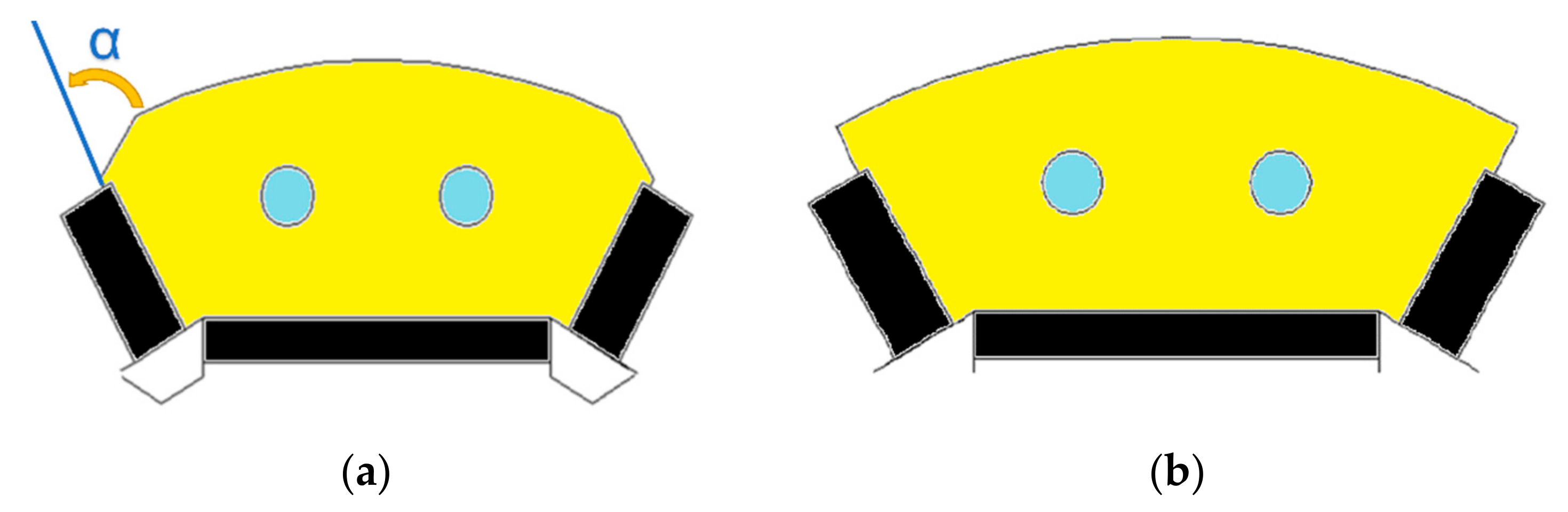
Section 3 has been adequately modified by changing the geometry of the rotor lamination pack while maintaining the same stator configuration. In more detail, referring to
Figure 6, the angle α, which is computed between the neutral axis and the lamination openings, has been changed from 60° (corresponding to its initial position) to 0° with steps of 10°, with a final refinement around the optimum α angle, which has led to the obtainment of eight models of IPMSM, corresponding to 60°, 50°, 40°, 33°, 30°, 20°, 10° and 0°. Other models have been obtained by increasing α instead of decreasing it. The model corresponding to α = 61° is presented here.
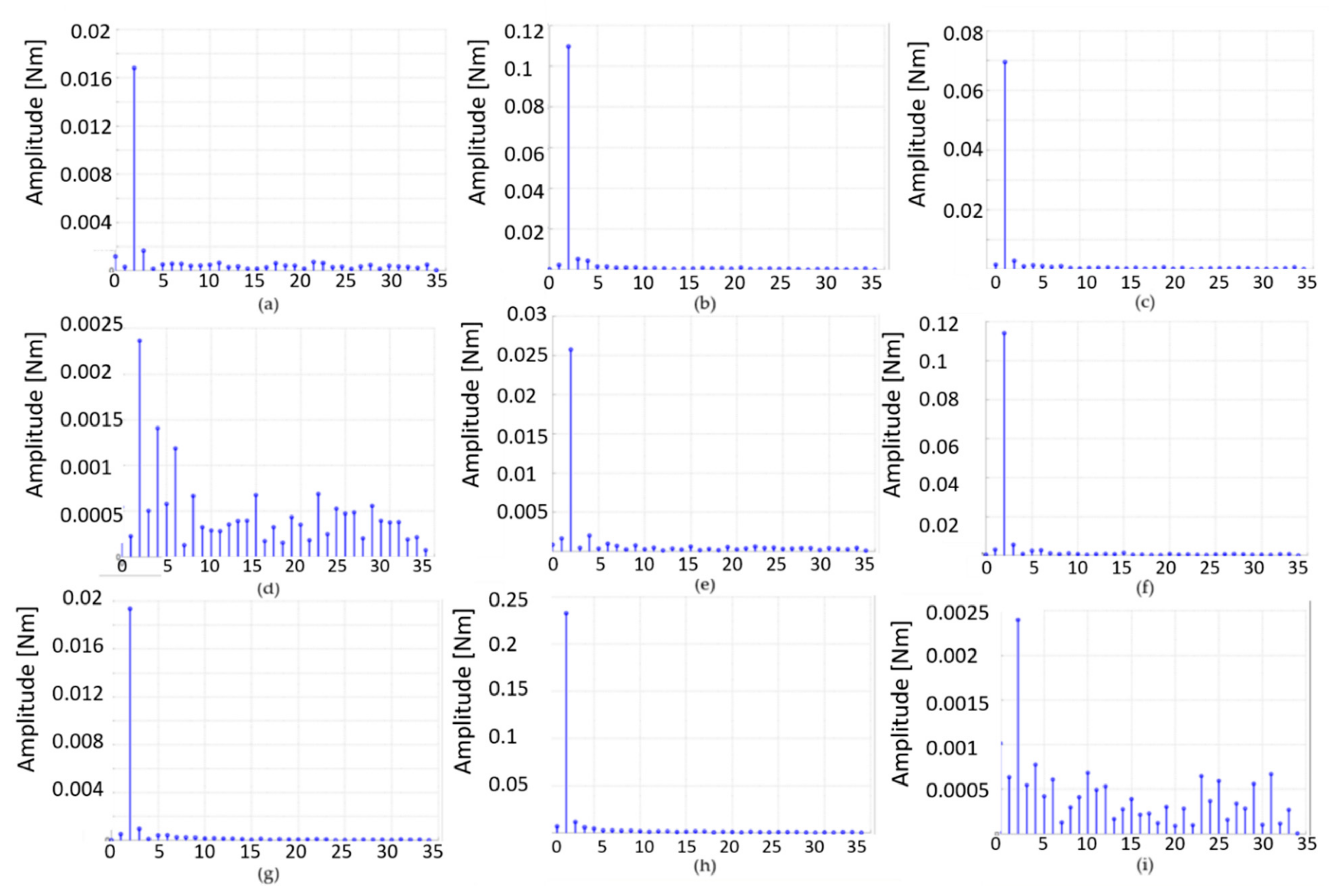
As well as for the basic IPMSM structure, the same FEM analysis has been performed for the other models, which has allowed the determination of the generated cogging torques, and
Figure 7 shows the related harmonic spectra for each of the proposed structures. From the comparison between these graphics related to the 9 IPMSM models designed with different angles of rotor laminations, it appears clear that the overall harmonic content detected with the optimized angles of 33° and 61° is minimized compared to the other configurations. Therefore, the rotor lamination of the initial configuration, whose spectrum presents a relatively high number of harmonics, has been optimally designed for the performance improvement of the machine.
This aspect can be also discussed from a numerical point of view. Indeed, the overall harmonic content, namely
Tx, can be computed by using the following equation:
where
Tin is the
n -order harmonic of the
i -order configuration and
N = 34.
Therefore, by referring to
Table 3, which summarizes the values of
Tx for each IPMSM structure, it can be noted that the best results are obtained with the optimized angles of 33° and 61°. The third column of the table reports the percentage values of
Tx with respect to
Tx0 = 0.230 Nm, corresponding to the worst possible condition in terms of harmonic content, as shown in
Figure 6b.
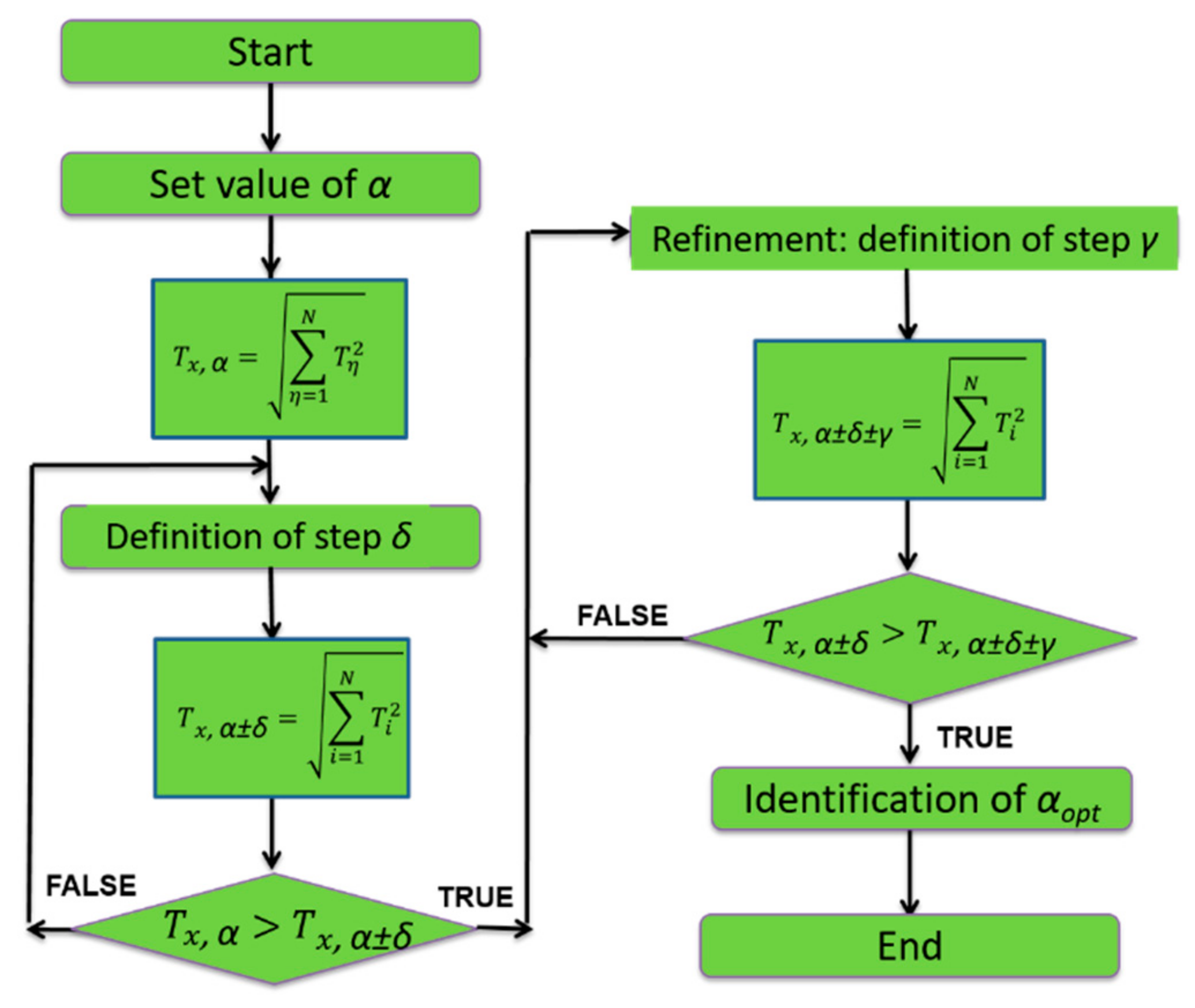
The optimization algorithm used for the determination of the α
opt of the rotor lamination geometry that minimizes the cogging torque is shown in
Figure 8. The search starts with the definition of the actual lamination angle and the determination of the corresponding harmonic content. The procedure continues with the definition of a step angle δ and with the computation of the harmonic content corresponding to the new lamination angle condition. The comparison between the obtained values establishes if the iteration process will continue with a refinement applied to find the optimal condition. This refinement process ends when the overall harmonic content is higher than the one obtained with the previous iteration process. In this case study, the step δ was fixed at 10°, whereas the refinement, detected between 30° and 40°, was fixed at 0.5°. These values can be set depending on the rotor lamination geometry and on the designer’s choice. Due to this aspect, the computational burden and the convergence speed depend on the setting of both the values of the initial and refinement steps.
6. Results and Discussions
This section aims to present the main results obtained from the FEM analysis of the IPMSM models described in the previous Sections, in order to compare their performance in terms of cogging torque reduction. A further objective is to compare the trends of both the radial and tangential components of the flux density field for all the models to verify that the proposed optimization procedure of the iron lamination geometry does not affect the overall electromagnetic behavior of the basic IPMSM configuration shown in
Figure 2. In detail, the processing of the data reported in
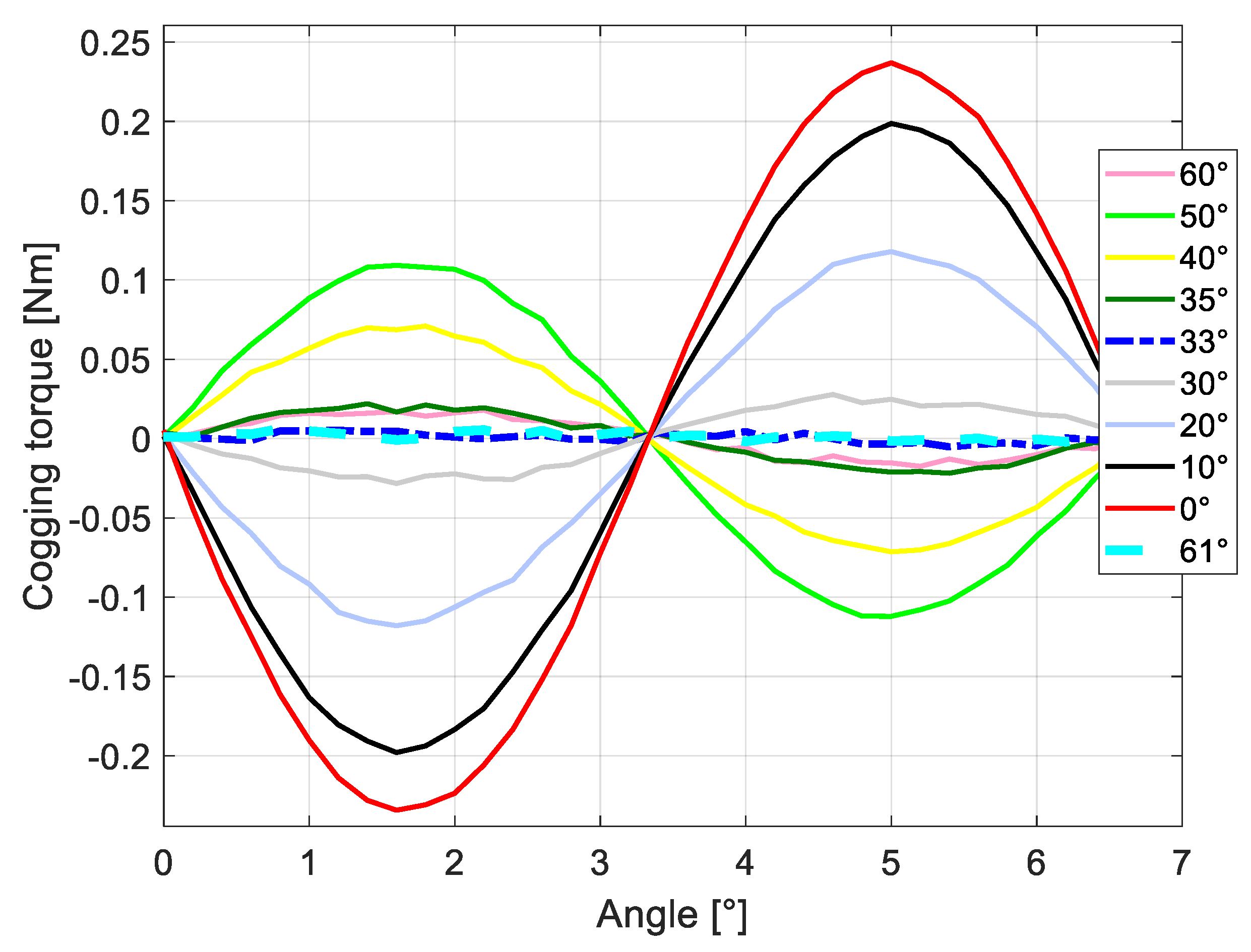
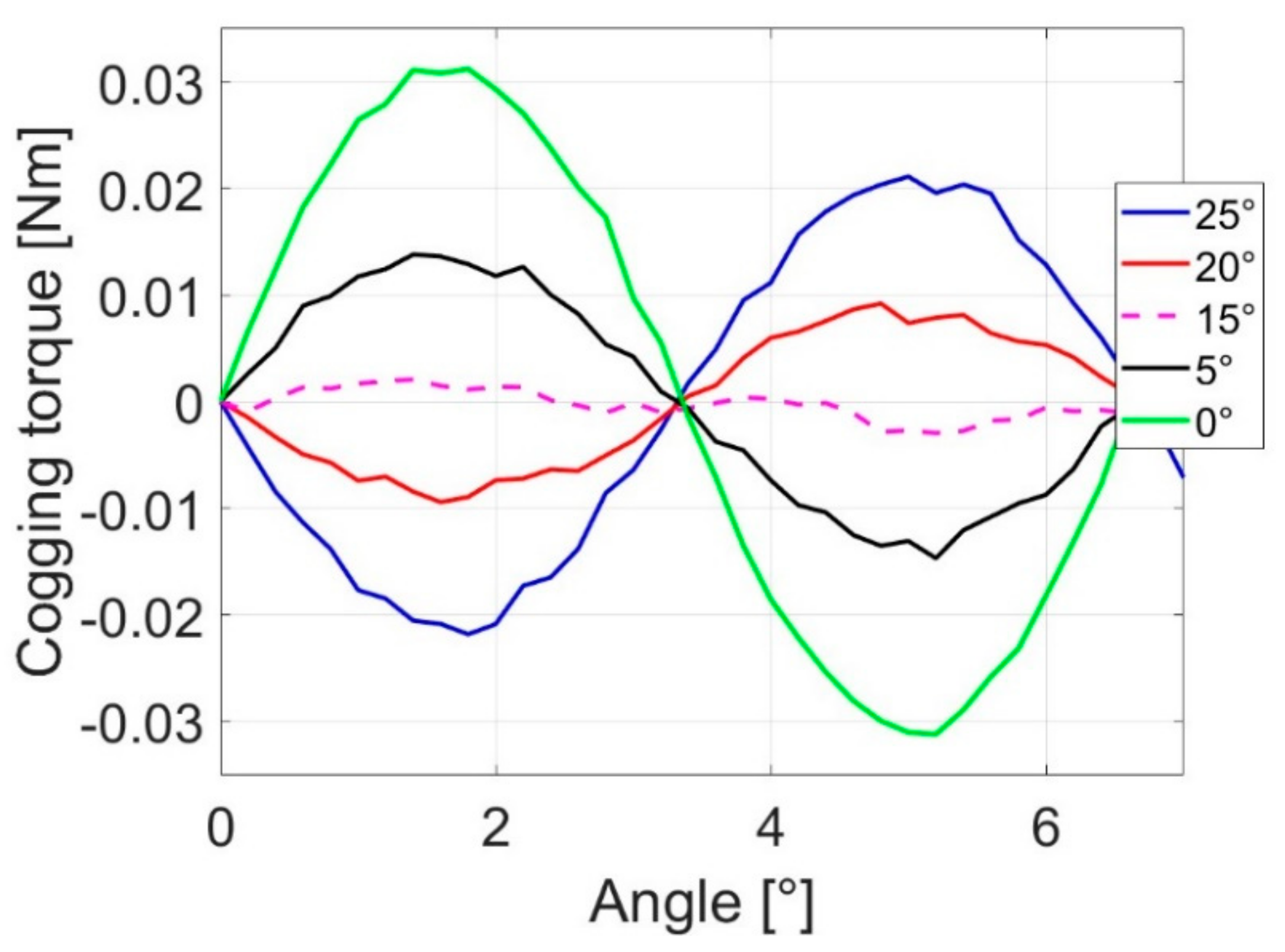
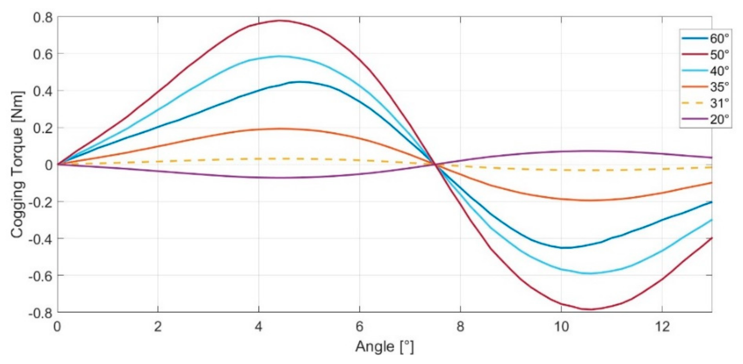
Section 5 has provided interesting results, hereinafter described. The FEM simulations have been carried out by referring to a specific rotor angular section equal to a polar arc area, corresponding to 60°. The comparison between the cogging torque/position angle characteristics parameterized as a function of α is shown in
Figure 9. It can be noted that the cogging torque amplitude relevantly decreases in the range of α between 30° and 40°. The optimized geometry of the rotor lamination corresponds to
, for which the cogging torque is almost canceled. This result can also be reached for
, as shown in the same graph. For α > 60°, the 1st harmonic values of the cogging torque would increase similarly to α < 60° and almost symmetrically to α = 50° (see
Figure 10). It has also to be stated that, with α > 60°, the structure of the lamination becomes more complex, leading to a reduction in practical feasibility. Moreover, regarding the manufacturing tolerances, which represent a common issue for many minimization techniques proposed in the recent literature, the accuracy of α, which leads to the accurate shape of the rotor lamination geometry, is crucial to ensure the effectiveness of the presented technique. It is, indeed, evident that a slight variation of α caused by manufacturing tolerances determines an increase of the cogging torque, even if around the optimum α value, not in a significant manner.
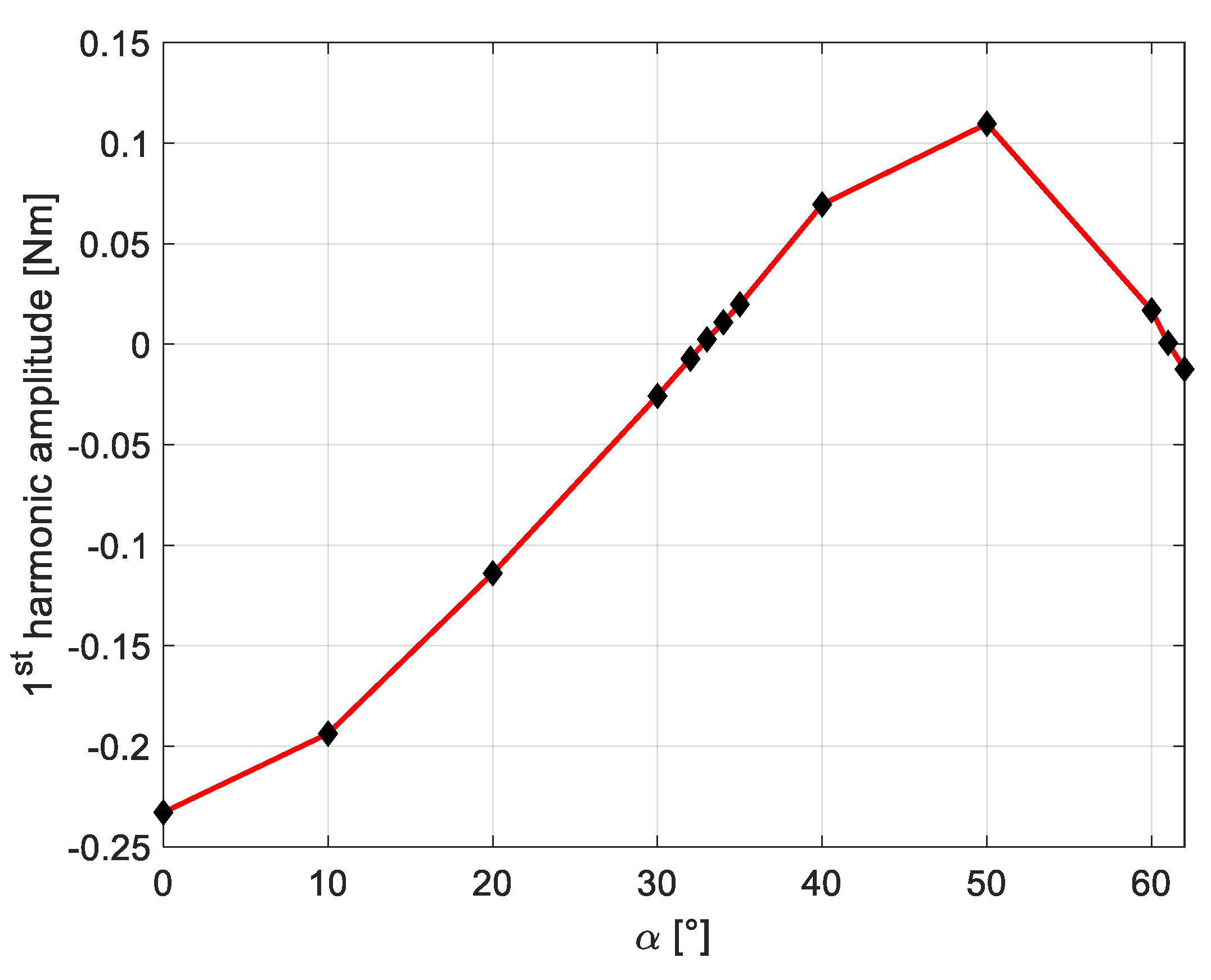
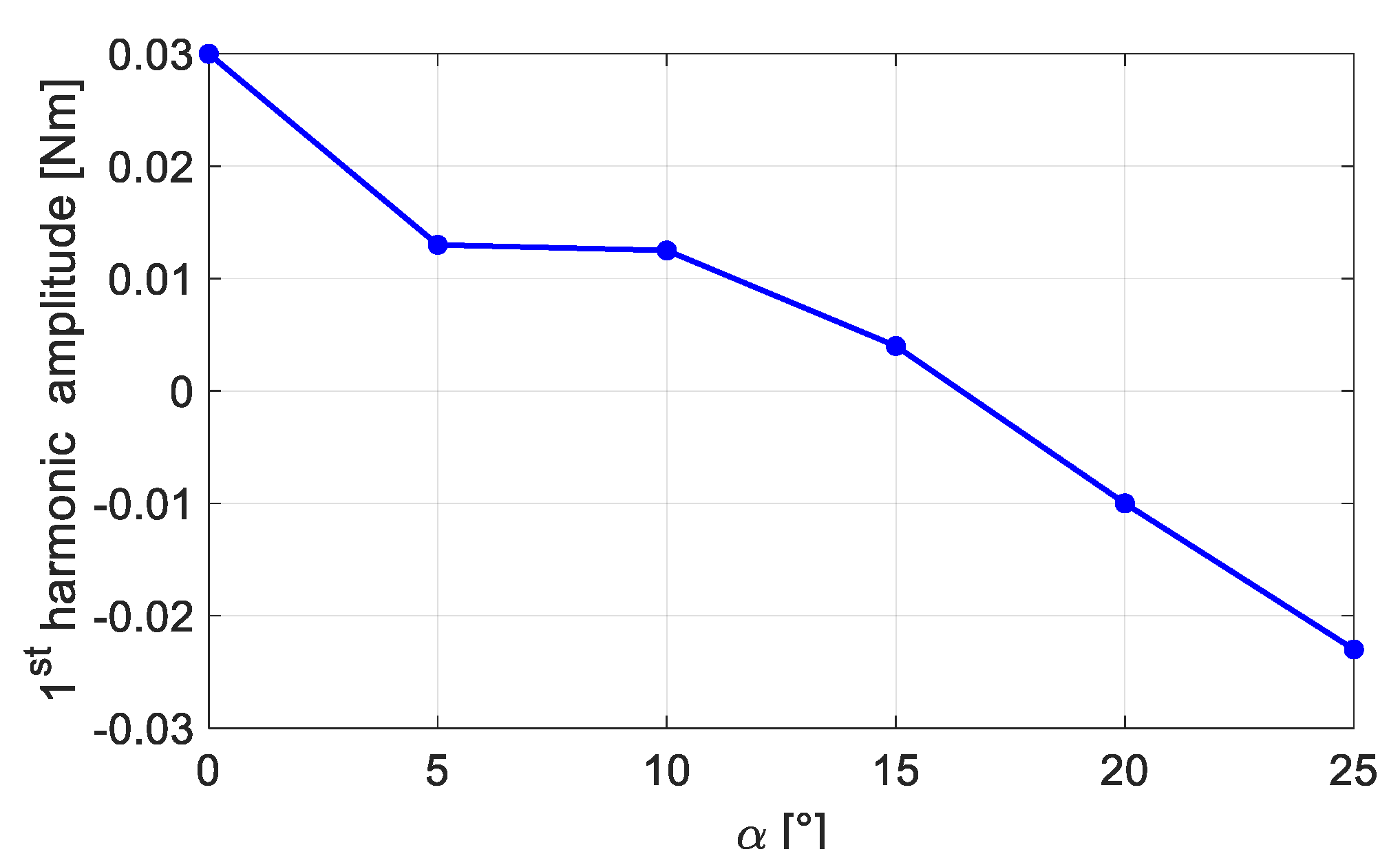
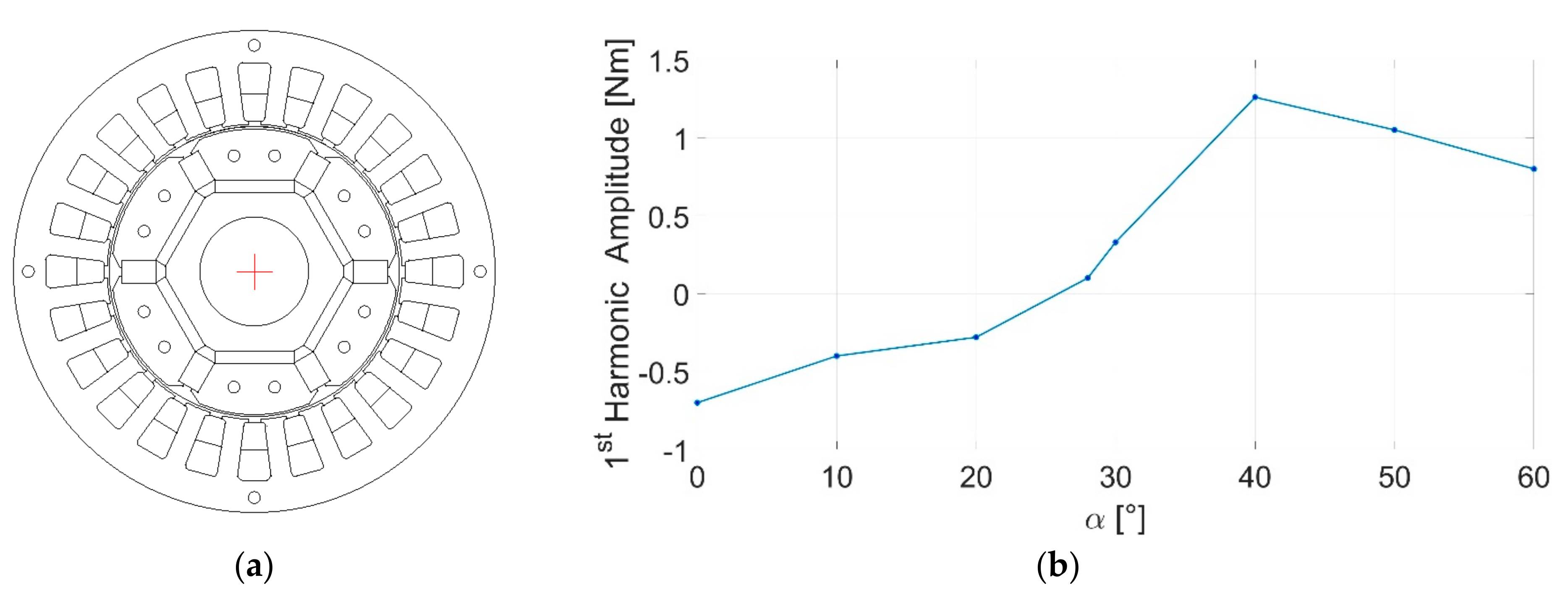
Moreover,
Figure 10 shows the trend of the 1st harmonic amplitudes of the cogging torque as a function of α. From this graph, it can be observed that two possible IPMSM configurations can achieve a condition of null cogging torque, corresponding to angles of 33° and 61°.
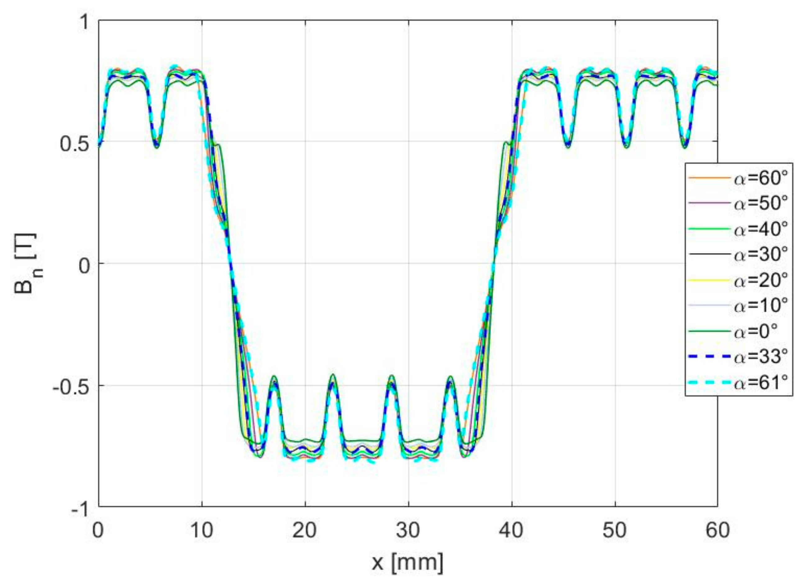
Furthermore, the spatial distribution of the flux density radial component
Bn measured along
x, which is defined as the mean air gap circumference, is not significantly affected by the described lamination refinements applied to the basic IPMSM. In fact, from the comparison between the
Bn/x trends generated by the proposed models shown in
Figure 11, the radial flux density maintains almost the same value at around 0.8 T. These considerations lead us to suppose that the maximum deliverable torque value is not significantly affected by the amplitude of the angle α. It can also be noted that the fluctuations of the cogging torque with the minimization procedure are limited.
From the graph in
Figure 11, it appears clear that the trend of the flux density field has not been significantly modified in terms of average value by the optimization procedure. The optimal modification of the iron lamination geometry has slightly changed the fluctuations of the flux density as well as its curvature.
In addition,
Figure 12 shows the comparison between the gradients of the radial flux densities around the neutral axis (quadrature axis) of the proposed configurations.
While α tends toward zero, two aspects can be detected: the average values of the related gradients increase and the shape of the gradient
dBn/
dx becomes more and more narrow and high, as depicted in
Figure 12.
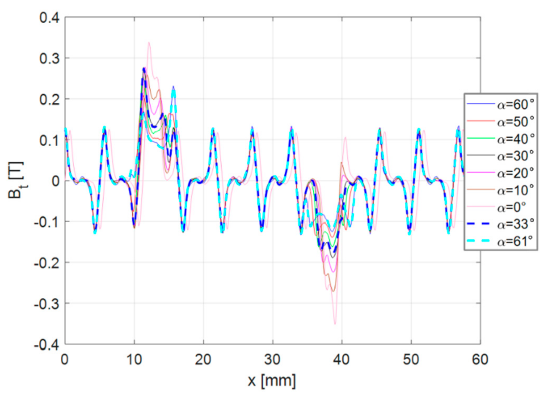
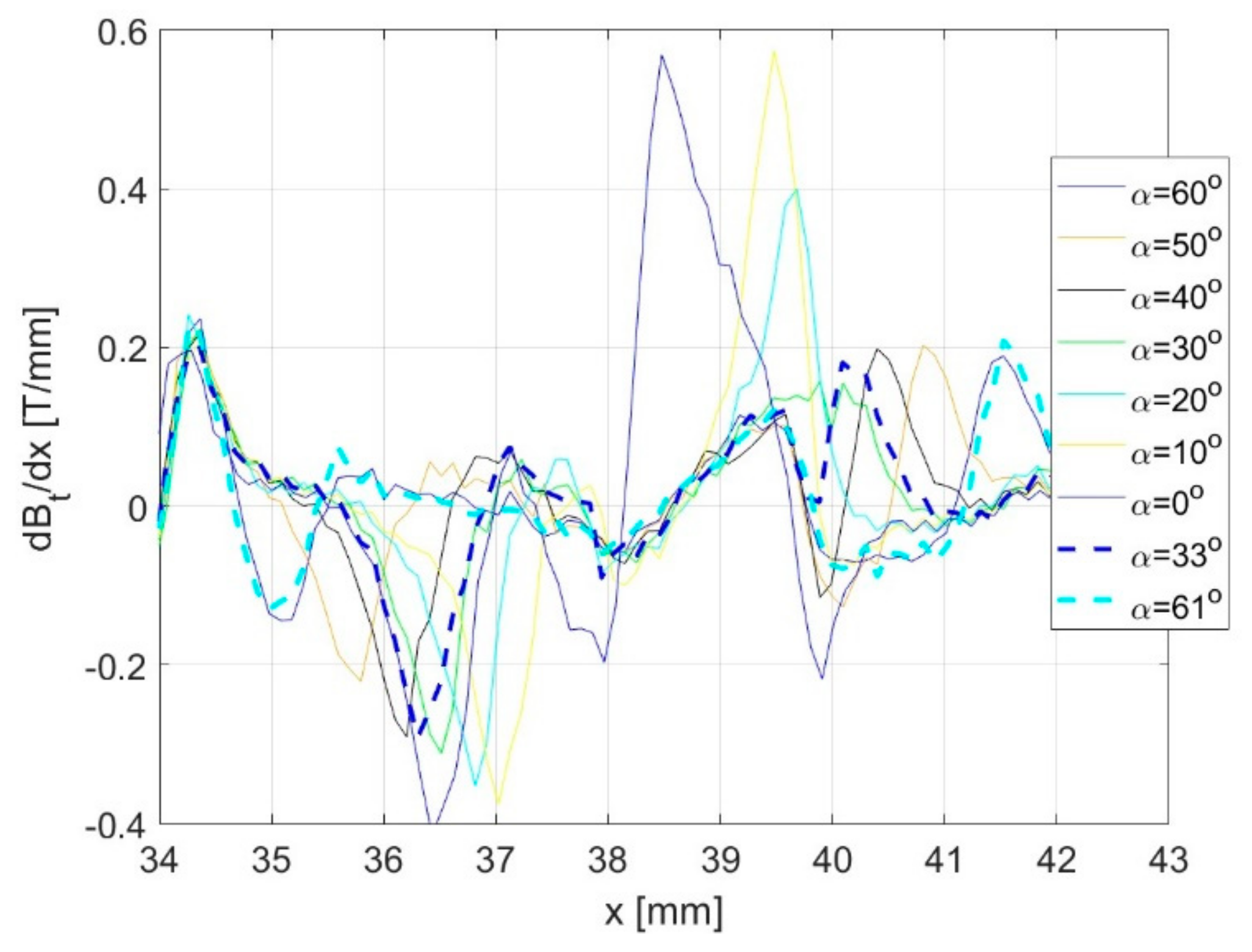
Other interesting results can be appreciated in
Figure 13, which shows the comparison between the trends of the tangential component
Bt of the flux density as a function of
x. As well as in the previous case, the flux density is not affected by the proposed modifications, except for the neutral axis region. Indeed, from this graph, it is evident that the trend of the tangential component of the flux density field has not been significantly affected regarding its average value by the optimal modification of the iron lamination. The proposed optimization procedure has changed both the fluctuations and the curvature of
Bt in a very slight manner.
The comparison between the
Bt gradients is shown in
Figure 14; as mentioned for the trend of the gradients of
Bn, for lower values of α, the average values of the related gradients increase. Therefore, with the optimum α configurations, lower gradient values are obtained.
By comparing the two optimal angles, it can be noted that α = 61° also provides a higher radial flux density, even if this difference is not as relevant.
In addition, with the aim of evaluating the impact of the proposed minimization procedure on other performance indexes for each of the analyzed models with different rotor lamination angles, the magnetic energy stored in the air-gap, the magnetic forces and the average air-gap magnetic field value at no load conditions have been computed and summarized in
Table 4. It can be noted that the cogging torque is minimized without affecting the performance of the machine. This aspect is also confirmed under load conditions by comparing the torque generated by the two models (basic IPMSM and optimized IPMSM) and the iron losses in both the stator and rotor cores. The obtained values are, indeed, comparable between each other, as shown in
Table 4.
In conclusion, it can be stated that the cogging torque generated in an IPMSM is significantly affected by the geometry of the rotor lamination. The results described in this Section have demonstrated that, at least in simulation, the cogging torque component can be almost completely canceled by adopting a very simple and fast optimization technique on the rotor lamination geometry. Therefore, the proposed optimization procedure can be used as an alternative method to the well-conceived minimization procedures presented in the recent literature for permanent magnet electric machines.
8. Conclusions
This article presents a simple cogging torque minimization procedure for IPMSMs, consisting of a progressive modification of the rotor lamination geometry. This procedure can be generalized for the main topologies of PMSM, independently from the number of stator slots or the location of the permanent magnets. The trends of the cogging torque generated by each model have been computed and compared, and the obtained results have demonstrated that, by simply acting on the shape of the rotor lamination and choosing the optimized pattern, the cogging torque components can be theoretically canceled, avoiding the adoption of expensive pole skewing techniques or other more complex methods. Moreover, it has been demonstrated that the proposed method does not affect the machine performance in a significant manner in terms of magnetization and average trend of the flux density field. In addition, the results presented in this paper have also demonstrated the easiness and fast optimization of the proposed method, which can be generalized for any PM machine, even if not clearly demonstrated here. In fact, the process of searching for the optimum angle of iron lamination can be easily implemented within an optimization algorithm, leading to a fast determination of the cogging torque suppression. In addition, the modification of the iron lamination geometry in an early design stage of the machine does not affect the overall cost of the fabrication process nor the complexity of the design procedure itself. Therefore, the proposed optimization procedure can be used as an alternative method to the well-conceived minimization procedures presented in the recent literature for permanent magnet electric machines.


