
Evaluation of the CO2 Storage Capacity in Sandstone Formations from the Southeast Mesohellenic trough (Greece)


 , , ,
, , ,  ,
,  , , and
Abstract
:1. Introduction
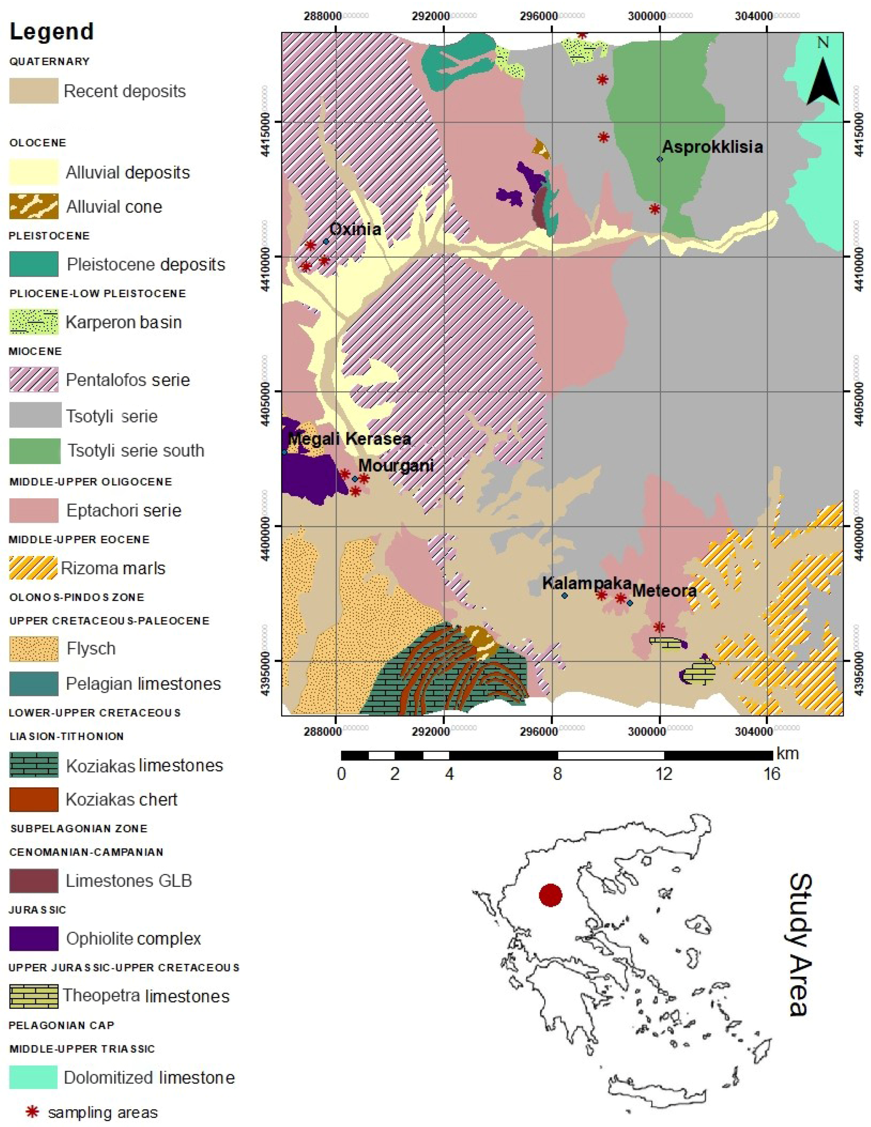
2. Study Area
3. Materials and Methods
3.1. Materials
3.2. Methods
4. Results
4.1. Petrographic Features and Mineral Chemistry
4.2. XRD Analyses
4.3. Clay Fraction
4.4. Geochemical Classification
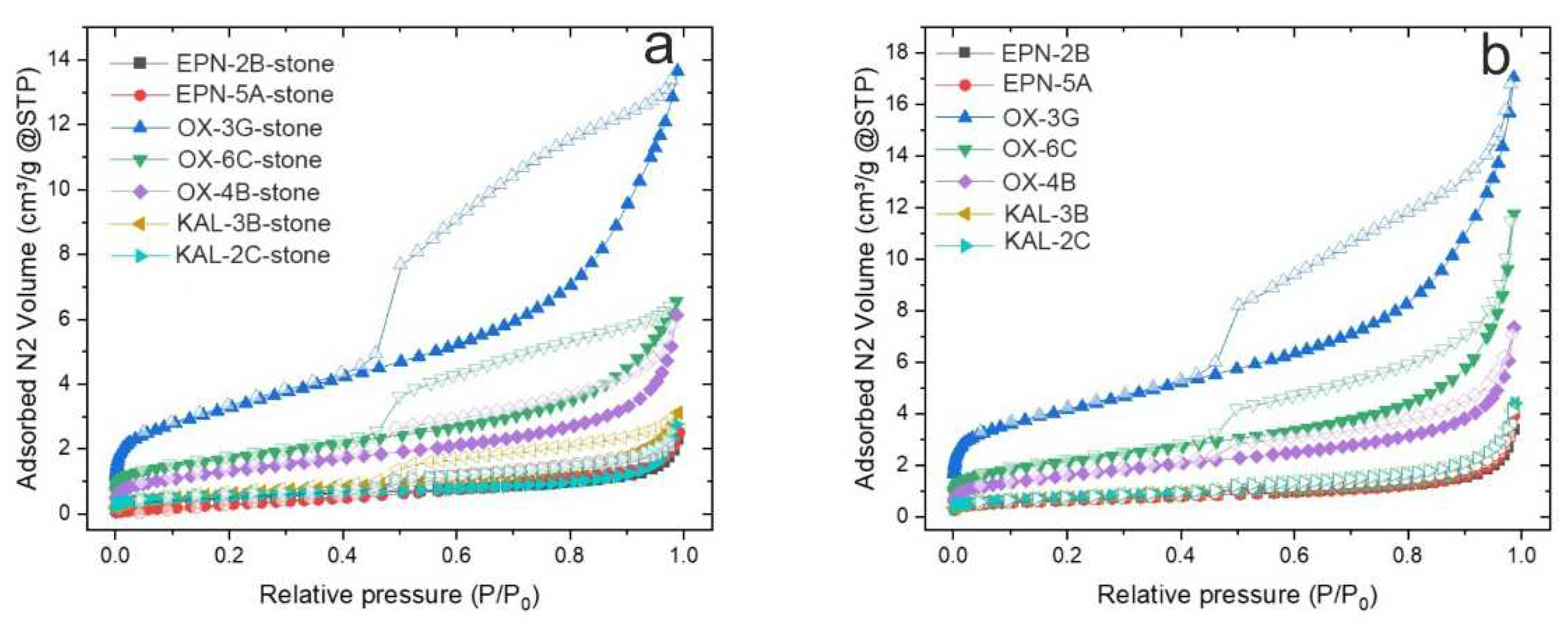
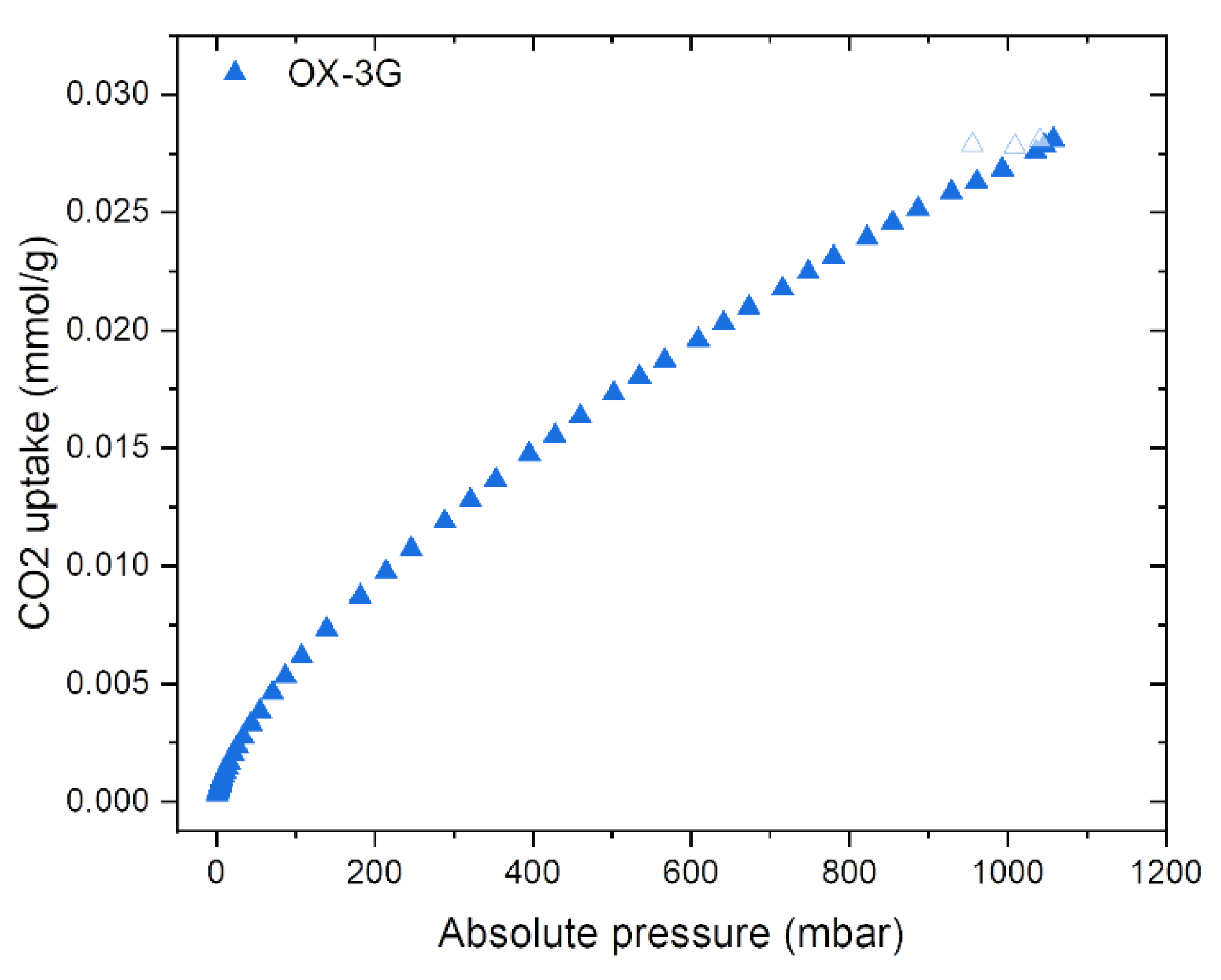
4.5. Gas Adsorption
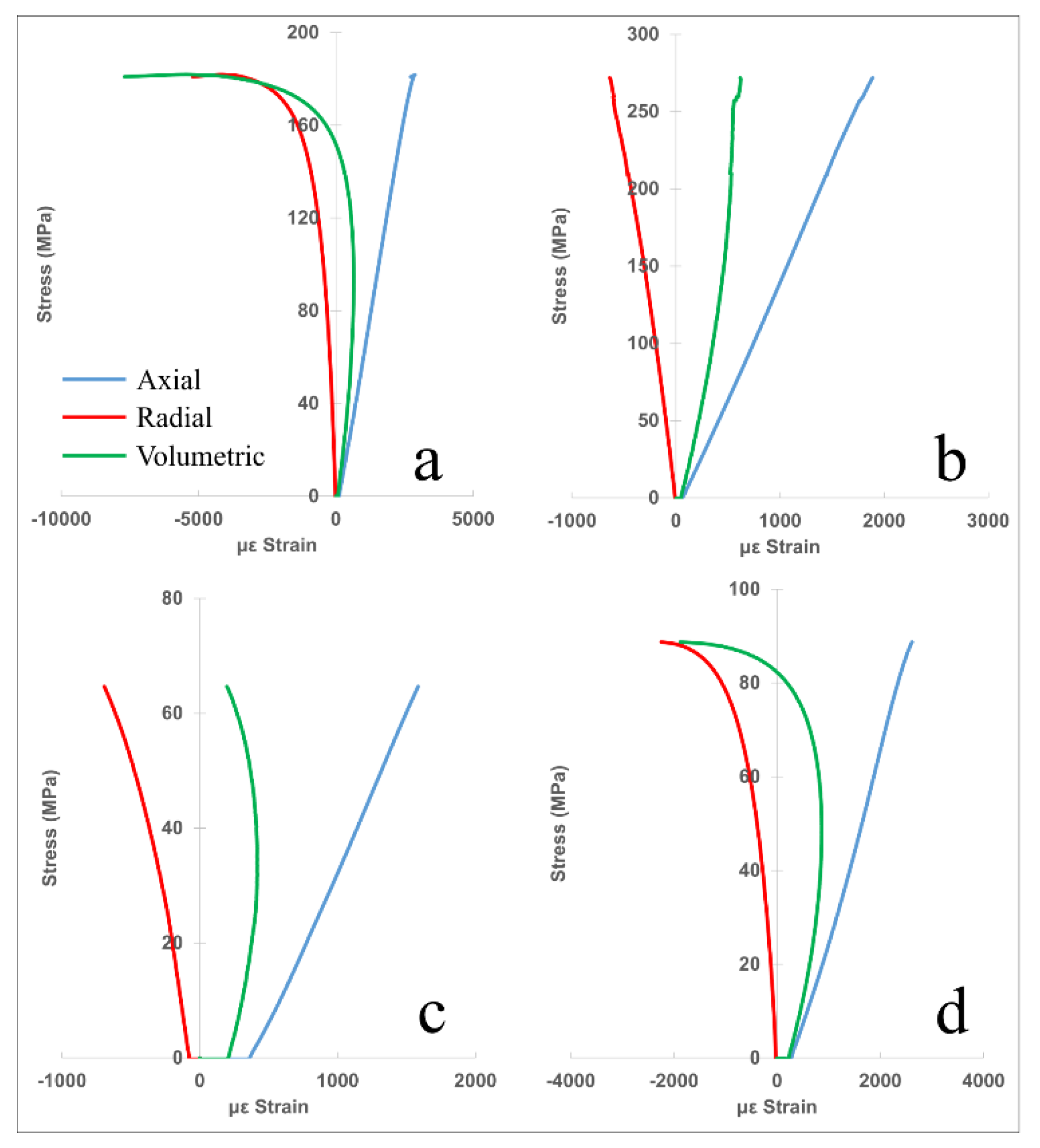
4.6. Mechanical Tests
5. Discussion
5.1. Suitability of Sandstones for CO2 Mineralization
5.2. Recommended CO2 Storage Site in the Mesohellenic Trough
6. Conclusions
- The petrographic characteristics of the Group I sandstones reveal that they have a better potential for CO2 storage due to the fact that they contain K-feldspars, plagioclase, epidote, serpentine, chlorite, and mica in relatively significant amounts; these are expected to react with CO2 and develop newly formed calcite, dolomite, and clay minerals. The latter mineral phases are commonly found in natural soils and, therefore, pose no harm to the environment.
- The proposed petrographic index, PrP, reveals the sandstones that incorporate relatively small amounts of mineral phases and that are susceptible to actively react with CO2.
- The gas adsorption results seem to be more encouraging for the Group I and II sandstones, coinciding with those that displayed optimal BET analyses results, pore volume values, and mineral modal compositions that are reactive to CO2 phases.
- The results of the mechanical strength testing of UCS, Ei, and ν revealed that these values highly depend upon the participating mineral phases but also on other parameters, such as their porosity values, as well as their textural features and participation of matrix material. The mechanical results are sufficiently in agreement with international standards to safely perform CO2 storage practices.
- The most promising site to be considered for pilot CO2 storage testing from the Southeast Mesohellenic Trough is that located in the Pentalofos Formation since it additionally holds the geological advantage of being overlaid by an impermeable cap-rock formation.
- The demarcated area could permanently store a calculated amount of ~50 × 105 tons of CO2 within the geological reservoir by reacting with the specified mineral phases.
Supplementary Materials
Author Contributions
Funding
Institutional Review Board Statement
Informed Consent Statement
Data Availability Statement
Acknowledgments
Conflicts of Interest
References
- Bachu, S. Sequestration of CO2 in geological media: Criteria and approach for site selection in response to climate change. Energy Convers. Manag. 2000, 41, 953–970. [Google Scholar] [CrossRef]
- IPCC. Special Report on CO2 Capture and Storage; Cambridge University Press: Cambridge, UK; New York, NY, USA, 2005. [Google Scholar]
- Li, Q.; Liu, G.; Liu, X.; Li, X. Application of a Health, Safety, and Environmental Screening and Ranking Framework to the Shenhua CCS Project. Int. J. Greenh. Gas Control 2013, 17, 504–514. [Google Scholar] [CrossRef]
- Yang, S.; Yu, Q. Experimental investigation on the movability of water in shale nanopores: A case study of Carboniferous shale from the Qaidam Basin, China. Water Resour. Res. 2020, 56, e2019WR026973. [Google Scholar] [CrossRef]
- Holloway, S. An overview of the underground disposal of carbon dioxide. Energy Convers. Manag. 1997, 38, S193–S198. [Google Scholar] [CrossRef]
- Juanes, R.; Spiteri, E.J.; Orr, F.M.; Blunt, M.J. Impact of relative permeability hysteresis on geological CO2 storage. Water Resour. Res. 2006, 42, 395–397. [Google Scholar] [CrossRef]
- Tolmachev, O.; Urunov, A.; Muminova, S.; Dvoichenkova, G.; Davydov, I. Review of unconventional hydrocarbon resources: Production technologies and opportunities for development. Min. Miner. Dep. 2020, 14, 113–121. [Google Scholar] [CrossRef]
- Chen, L.; Zhao, M.; Li, X.; Liu, Y. Impact research of CH4 replacement with CO2 in hydrous coal under high pressure injection. Min. Miner. Dep. 2022, 16, 121–126. [Google Scholar] [CrossRef]
- Jia, B.; Chen, Z.; Xian, C. Investigations of CO2 storage capacity and flow behavior in shale formation. J. Petrol. Sci. Eng. 2022, 208, 109659. [Google Scholar] [CrossRef]
- Munz, I.A.; Brandvoll, Ø.; Haug, T.A.; Iden, K.; Smeets, R.; Kihle, J.; Johansen, H. Mechanisms and rates of plagioclase carbonation reactions. Geochim. Cosmochim. Acta 2012, 77, 27–51. [Google Scholar] [CrossRef]
- Ghacham, A.B.; Cecchi, E.; Pasquier, L.C.; Blais, J.F.; Mercier, C. CO2 sequestration using waste concrete and anorthosite tailings by direct mineral carbonation in gas–solid–liquid and gas–solid routes. J. Environ. Manag. 2015, 163, 70–77. [Google Scholar] [CrossRef]
- Yang, L.; Xu, T.; Feng, G.; Liu, K.; Tian, H.; Peng, B.; Wang, C. CO2-induced geochemical reactions in heterogeneous sandstone and potential conditions causing the tight cementation. Appl. Geochem. 2017, 80, 14–23. [Google Scholar] [CrossRef]
- Wilson, M.; Monea, M. IEA GHG Weyburn CO2 monitoring and storage project: Summary report 2000–2001. In Proceedings of the 7th International Conference Greenhouse Gas Control Technology (GHGT-7), Vancouver, BC, Canada, 5–9 September 2005. [Google Scholar]
- Jin, C.; Liu, L.; Yiman, L.; Zeng, R. Capacity assessment of CO2 storage in deep saline aquifers by mineral trapping and the implications for Songliao Basin, Northeast China. Energy Sci. Eng. 2017, 5, 81–89. [Google Scholar] [CrossRef]
- Wang, Y.; Zan, N.; Cao, X.; Cao, Y.; Yuan, G.; Gluyas, J.G.; Lin, M. Geologic CO2 storage in arkosic sandstones with CaCl2-rich formation water. Chem. Geol. 2020, 558, 119867. [Google Scholar]
- Koukouzas, N.; Kypritidou, Z.; Purser, G.; Rochelle, C.A.; Vasilatos, C.; Tsoukalas, N. Assessment of the impact of CO2 storage in sandstone formations by experimental studies and geochemical modeling: The case of the Mesohellenic Trough, NW Greece. Int. J. Greenh. Gas Control 2018, 71, 116–132. [Google Scholar] [CrossRef]
- Alemu, B.L.; Aagaard, P.; Munz, I.A.; Skurtveit, E. Caprock interaction with CO2: A laboratory study of reactivity of shale with supercritical CO2 and brine. Appl. Geochem. 2011, 26, 1975–1989. [Google Scholar] [CrossRef]
- Huq, F.; Blum, P.; Marks, M.A.W.; Nowak, M.; Haderlein, S.B.; Grathwohl, P. Chemical changes in fluid composition due to CO2 injection in the Altmark gas field: Preliminary results from batch experiments. Environ. Earth Sci. 2012, 67, 385–394. [Google Scholar] [CrossRef]
- Garcia-Rios, M.; Luquot, L.; Soler, J.; Cama, J. Laboratory-Scale Interaction between CO2-Rich Brine and Reservoir Rocks (Limestone and Sandstone). Procedia Earth Planet. Sci. 2013, 7, 109–112. [Google Scholar] [CrossRef] [Green Version]
- Ni, H.; Boon, M.; Garing, C.; Benson, S.M. Predicting CO2 residual trapping ability based on experimental petrophysical properties for different sandstone types. Int. J. Greenh. Gas Control 2019, 86, 158–176. [Google Scholar] [CrossRef]
- Wigand, M.; Carey, J.W.; Schütt, H.; Spangenberg, E.; Erzinger, J. Geochemical effects of CO2 sequestration in sandstones under simulated in situ conditions of deep saline aquifers. Appl. Geochem. 2008, 23, 2735–2745. [Google Scholar] [CrossRef]
- Tasianas, A.; Koukouzas, N. CO2 Storage Capacity Estimate in the Lithology of the Mesohellenic Trough, Greece. Energy Procedia 2016, 86, 334–341. [Google Scholar] [CrossRef] [Green Version]
- Brunn, J.H. Contribution à l’étude géologique du Pinde septentrional et d’une partie de la Macédoine occidentale. Ann. Géol. 1956, 8, 346–358. [Google Scholar]
- Aubouin, J. Contribution à l’ étude géologique de la Grèce septentrionale: Le confins de l’Epire et de la Thessalie. Ann. Géol. 1959, 10, 525. [Google Scholar]
- Papanikolaou, D.; Lekkas, E.; Mariolakos, E.; Mirkou, R. Contribution on the geodynamic evolution of the Mesohellenic trough. Bull. Geol. Soc. Greece 1988, 20, 17–36. [Google Scholar]
- Vamvaka, A. Geometry of Deformation and Kinematic Analysis in Mesohellenic Trough. Ph.D. Thesis, Aristotle University of Thessaloniki, Department of Geology, Thessaloniki, Greece, 2009. [Google Scholar]
- Rassios, A.; Moores, E. Heterogeneous mantle complex, crustal processes, and obduction kinematics in a unified Pindos-Vourinos ophiolitic slab (northern Greece). Geol. Soc. Lond. 2006, 260, 237–266. [Google Scholar] [CrossRef]
- Kilias, A.D.; Vamvaka, A.; Falalakis, G.; Sfeikos, A.; Papadimitriou, E.; Gkarlaouni, C.H.; Karakostas, B. The Mesohellenic Trough and the Paleogene Thrace Basin on the Rhodope Massif, their Structural Evolution and Geotectonic Significance in the Hellenides. J. Geol. Geosci. 2015, 4, 1–17. [Google Scholar]
- Koukouzas, N.; Krassakis, P.; Koutsovitis, P.; Karkalis, C. An integrated approach to the coal deposits in the Mesohellenic Trough, Greece. Bull. Geol. Soc. Greece 2019, 54, 34–59. [Google Scholar] [CrossRef] [Green Version]
- EN 932; Part 3: Procedure and Terminology for Simplified Petrographic Description. European Standard: Warsaw, Poland, 1996.
- Bish, D.L.; Post, J.E. Quantitative mineralogical analysis using the Rietveld full pattern fitting method. Am. Mineral. 1993, 78, 932–940. [Google Scholar]
- ASTM D 7348; Standard Test Methods for Loss on Ignition (LOI) of Solid Combustion, Residues. ASTM International: West Conshohocken, PA, USA, 2011.
- Lanari, P.; Wagner, T.; Vidal, O. A thermodynamic model for di-trioctahedral chlorite from experimental and natural data in the system MgO–FeO–Al2O3–SiO2–H2O: Applications to P–T sections and geothermometry. Contrib. Mineral. Petrol. 2014, 167, 968. [Google Scholar] [CrossRef] [Green Version]
- Hey, M.H. A review on the chlorites. Mineral. Mag. 1954, 30, 277–298. [Google Scholar]
- Pettijohn, D.E. Ordered and preferential initiation of ribosomal RNA synthesis in vitro. Nat. New Biol. 1972, 235, 204–206. [Google Scholar] [CrossRef]
- Herron, M.M. Geochemical classification of terrigenous sands and shales from core or log data. J. Sediment. Res. 1988, 58, 820–829. [Google Scholar]
- Thommes, M.; Kaneko, K.; Neimark, A.V.; Olivier, J.P.; Rodriguez-Reinoso, F.; Rouquerol, J.; Sing, K.S.W. Physisorption of gases, with special reference to the evaluation of surface area and pore size distribution (IUPAC Technical Report). Pure Appl. Chem. 2015, 87, 1051–1069. [Google Scholar] [CrossRef] [Green Version]
- Sabatakakis, N.; Tsiambaos, G.; Ktena, S.; Bouboukas, S. The effect of microstructure on mi strength parameter variation of common rock types. Bull. Eng. Geol. Environ. 2018, 77, 1673–1688. [Google Scholar] [CrossRef]
- Paraskevopoulou, C.; Perras, M.; Diederichs, M.; Amann, F.; Löw, S.; Lam, T.; Jensen, M. The three stages of stress relaxation-Observations for the time-dependent behaviour of brittle rocks based on laboratory testing. Eng. Geol. 2017, 216, 56–75. [Google Scholar] [CrossRef]
- Whitney, D.L.; Evans, B.W. Abbreviations for names of rock-forming minerals. Am. Mineral. 2010, 95, 185–187. [Google Scholar] [CrossRef]
- Zhang, P.; Misch, D.; Hu, F.; Kostoglou, N.; Sachsenhofer, R.F.; Liu, Z.; Meng, Q.; Bechtel, A. Porosity evolution in organic matter-rich shales (Qingshankou Fm.; Songliao Basin, NE China): Implications for shale oil retention. Mar. Petrol. Geol. 2021, 130, 105139. [Google Scholar] [CrossRef]
- Matter, J.M.; Kelemen, P.B. Permanent storage of carbon dioxide in geological reservoirs by mineral carbonation. Nat. Geosci. 2009, 2, 837–841. [Google Scholar] [CrossRef]
- Brown, G.E.; Bird, D.K.; Kendelewicz, T.; Maher, K.; Mao, W.; Johnson, N.; Rosenbauer, R.J.; García Del Real, P. Geological Sequestration of CO2: Mechanisms and Kinetics of CO2 Reactions with Mafic and Ultramafic Rock Formations. In Annual Report to the Global Climate and Energy Project; Stanford University: Stanford, CA, USA, 2009. [Google Scholar]
- Dichicco, M.C.; Laurita, S.; Paternoster, M.; Rizzo, G.; Sinisi, R.; Mongelli, G. Serpentinite Carbonation for CO2 Sequestration in the Southern Apennines: Preliminary Study. Energy Procedia 2015, 76, 477–486. [Google Scholar] [CrossRef] [Green Version]
- McGrail, B.P.; Schaef, H.T.; Spane, F.A.; Cliff, J.B.; Qafoku, O.; Horner, J.A.; Thompson, C.J.; Owen, A.T.; Sullivan, C.E. Field validation of supercritical CO2 reactivity with basalts. Environ. Sci. Technol. Lett. 2017, 4, 6–10. [Google Scholar] [CrossRef]
- Koukouzas, N.; Koutsovitis, P.; Tyrologou, P.; Karkalis, C.; Arvanitis, A. Potential for Mineral Carbonation of CO2 in Pleistocene Basaltic Rocks in Volos Region (Central Greece). Minerals 2019, 9, 627. [Google Scholar] [CrossRef] [Green Version]
- Iglauer, S.; Pentland, C.H.; Busch, A. CO2 wettability of seal and reservoir rocks and the implications for carbon geo-sequestration. Water Resour. Res. 2015, 51, 729–774. [Google Scholar] [CrossRef] [Green Version]
- Hangx, S.J.; Spiers, C.J. Reaction of plagioclase feldspars with CO2 under hydrothermal conditions. Chem. Geol. 2009, 265, 88–98. [Google Scholar] [CrossRef]
- Gaus, I. Role and impact of CO2-rock interactions during CO2 storage in sedimentary rocks. Int. J. Greenh. Gas Control 2010, 4, 73–89. [Google Scholar] [CrossRef]
- Kampman, N.; Bickle, M.; Wigley, M.; Dubacq, B. Fluid flow and CO2-fluid-mineral interactions during CO2-storage in sedimentary basins. Chem. Geol. 2014, 369, 22–50. [Google Scholar] [CrossRef]
- Aradóttir, E.S.P.; Sonnenthal, E.L.; Björnsson, G.; Jónsson, H. Multidimensional reactive transport modeling of CO2 mineral sequestration in basalts at the Hellisheidi geothermal field, Iceland. Int. J. Greenh. Gas Control 2012, 9, 24–40. [Google Scholar] [CrossRef] [Green Version]
- Snæbjörnsdóttir, S.Ó.; Gislason, S.R.; Galeczka, I.M.; Oelkers, E.H. Reaction path modelling of in-situ mineralisation of CO2 at the CarbFix site at Hellisheidi, SW-Iceland. Geochim. Cosmochim. Acta 2018, 220, 348–366. [Google Scholar] [CrossRef] [Green Version]
- Marieni, C.; Voigt, M.J.; Oelkers, E.H. Experimental study of epidote dissolution rates from pH 2 to 11 and temperatures from 25 to 200 °C. Geochim. Cosmochim. Acta 2021, 294, 70–88. [Google Scholar] [CrossRef]
- Snæbjörnsdóttir, S.Ó.; Wiese, F.; Fridriksson, T.; Ármansson, H.; Einarsson, G.M.; Gislason, S.R. CO2 storage potential of basaltic rocks in Iceland and the oceanic ridges. Energy Procedia 2014, 63, 4585–4600. [Google Scholar] [CrossRef] [Green Version]
- Kelemen, P.B.; McQueen, N.; Wilcox, J.; Renforth, P.; Dipple, G.; Vankeuren, A.P. Engineered carbon mineralization in ultramafic rocks for CO2 removal from air: Review and new insights. Chem. Geol. 2020, 550, 119628. [Google Scholar] [CrossRef]
- Park, A.H.A.; Fan, L.S. CO2 mineral sequestration: Physically activated dissolution of serpentine and pH swing process. Chem. Eng. Sci. 2004, 59, 5241–5247. [Google Scholar] [CrossRef]
- Pokrovsky, O.S.; Golubev, S.V.; Schott, J. Dissolution kinetics of calcite, dolomite and magnesite at 25 °C and 0 to 50 atm pCO2. Chem. Geol. 2005, 217, 239–255. [Google Scholar] [CrossRef]
- Arvanitis, A.; Koutsovitis, P.; Koukouzas, N.; Tyrologou, P.; Karapanos, D.; Karkalis, C.; Pomonis, P. Potential Sites for Underground Energy and CO2 Storage in Greece: A Geological and Petrological Approach. Energies 2020, 13, 2707. [Google Scholar] [CrossRef]
- Meer, L.G.H.; Hofstee, C.; Orlic, B. The fluid flow consequences of CO2 migration from 1000 to 600 metres upon passing the critical conditions of CO2. Energy Procedia 2009, 1, 3213–3220. [Google Scholar] [CrossRef] [Green Version]


| Mineral | P|g (Ab) | Plg (Olg-Andes) | Kfs | Ep | Srp | Bt | Chl | Aln | Mnz |
|---|---|---|---|---|---|---|---|---|---|
| n: | 7 | 5 | 18 | 8 | 6 | 9 | 7 | 3 | 4 |
| SiO2 | 67.36 | 62.84 | 67.04 | 39.11 | 45.62 | 51.33 | 37.83 | 40.90 | 10.74 |
| 1σ | 0.84 | 1.37 | 1.21 | 1.17 | 1.10 | 1.94 | 2.74 | 0.95 | 0.89 |
| TiO2 | - | - | - | - | - | 1.45 | - | - | |
| 1σ | - | - | - | - | - | 0.87 | - | - | - |
| AI2O3 | 19.92 | 23.72 | 17.44 | 23.84 | 1.46 | 21.54 | 15.31 | 22.35 | 6.18 |
| 1σ | 1.09 | 1.64 | 0.67 | 1.16 | 0.74 | 2.28 | 1.22 | 0.91 | 4.85 |
| FeO | 0.16 | 0.08 | 0.16 | 9.41 | 6.34 | 7.41 | 14.61 | 12.32 | 2.07 |
| 1σ | 0.09 | 0.04 | 0.05 | 1.48 | 0.81 | 2.34 | 3.18 | 1.58 | 1.95 |
| MgO | - | - | - | 0.38 | 33.49 | 5.27 | 18.64 | - | 1.17 |
| 1σ | - | - | - | - | 1.63 | 1.45 | 3.26 | - | |
| CaO | 1.24 | 4.32 | 0.25 | 24.17 | 0.59 | - | 0.79 | 13.69 | 3.21 |
| 1σ | 0.68 | 1.30 | 0.07 | 1.42 | 0.12 | - | 0.20 | 0.19 | 3.14 |
| Na2O | 10.76 | 8.62 | 0.81 | - | - | - | - | - | - |
| 1σ | 0.92 | 0.82 | 0.62 | - | - | - | - | - | - |
| K2O | 0.57 | 0.29 | 14.21 | - | - | 9.57 | - | - | - |
| 1σ | 0.23 | 0.11 | 0.54 | - | - | 0.82 | - | - | - |
| P2O5 | - | - | - | - | - | - | - | - | 29.82 |
| 1σ | - | - | - | - | - | - | - | - | 4.99 |
| La2O3 | - | - | - | - | - | - | - | 3.85 | 13.90 |
| 1σ | - | - | - | - | - | - | - | 0.43 | 1.72 |
| Ce2O3 | - | - | - | - | - | - | - | 7.87 | 29.47 |
| 1σ | - | - | - | - | - | - | - | 0.09 | 2.52 |
| Y2O3 | - | - | - | - | - | - | - | - | 27.08 |
| 1σ | - | - | - | - | - | - | - | - | 2.37 |
| Nd2O3 | - | - | - | - | - | - | - | - | 10.48 |
| 1σ | - | - | - | - | - | - | - | - | 1.49 |
| Total | 99.85 | 99.87 | 99.91 | 96.91 | 87.19 | 96.57 | 87.18 | 99.05 | 97.63 |
| Mineral | Plg (Ab) | Plg (Olg) | Kfs | Ep | Srp | Bt | Chl | Aln |
|---|---|---|---|---|---|---|---|---|
| n: | 8 | 7 | 11 | 5 | 2 | 6 | 5 | 2 |
| SiO2 | 67.55 | 63.45 | 66.62 | 38.52 | 47.9 | 52.48 | 39.24 | 40.09 |
| 1σ | 1.03 | 1.45 | 1.28 | 0.73 | 0.56 | 0.73 | 2.16 | 0.95 |
| TiO2 | - | - | - | - | - | 1.22 | - | - |
| 1σ | - | - | - | - | - | 0.36 | - | - |
| AI2O3 | 19.87 | 23.38 | 17.78 | 24.32 | 2.03 | 21.12 | 14.84 | 22.35 |
| 1σ | 1.31 | 1.55 | 1.16 | 0.44 | 0.07 | 2.86 | 2.33 | 0.91 |
| FeO | 0.19 | 0.12 | 0.18 | 9.69 | 4.89 | 7.12 | 15.76 | 12.32 |
| 1σ | 0.08 | 0.06 | 0.11 | 0.98 | 0.02 | 1.83 | 3.4 | 1.58 |
| MgO | - | - | - | - | 31.58 | 5.93 | 16.43 | - |
| 1σ | - | - | - | - | 0.67 | 2.26 | 2.75 | - |
| CaO | 1.11 | 3.55 | 0.28 | 23.76 | 0.32 | - | 0.77 | 13.68 |
| 1σ | 0.88 | 0.80 | 0.12 | 0.76 | 0.05 | - | 0.42 | 0.19 |
| Na2O | 10.68 | 9.15 | 0.83 | - | - | - | - | - |
| 1σ | 0.71 | 0.61 | 0.42 | - | - | - | - | - |
| K2O | 0.46 | 0.24 | 14.27 | - | - | 9.19 | - | - |
| 1σ | 0.50 | 0.22 | 1.35 | - | - | 1.13 | - | - |
| La2O3 | - | - | - | - | - | - | - | 3.85 |
| 1σ | - | - | - | - | - | - | - | 0.58 |
| Ce2O3 | - | - | - | - | - | - | - | 7.86 |
| 1σ | - | - | - | - | - | - | - | 0.09 |
| Total | 99.86 | 99.89 | 99.96 | 96.29 | 86.72 | 97.06 | 87.04 | 100.15 |
| Mineral | Plg (Ab) | Kfs | Ep | Bt | Chl |
|---|---|---|---|---|---|
| n: | 5 | 5 | 3 | 4 | 4 |
| SiO2 | 67.75 | 66.86 | 39.67 | 53.72 | 39.86 |
| 1σ | 1.16 | 0.63 | 0.41 | 2.23 | 1.47 |
| TiO2 | - | - | - | 0.78 | - |
| 1σ | - | - | - | 0.39 | - |
| AI2O3 | 19.65 | 17.56 | 23.21 | 23.72 | 15.03 |
| 1σ | 1.02 | 0.41 | 0.33 | 2.63 | 0.84 |
| FeO | 0.14 | 0.21 | 10.41 | 6.51 | 16.61 |
| 1σ | 0.07 | 0.09 | 0.25 | 2.53 | 0.36 |
| MgO | - | - | - | 4.71 | 14.82 |
| 1σ | - | - | - | 1.61 | 0.39 |
| CaO | 1.18 | 0.15 | 23.23 | - | 0.47 |
| 1σ | 0.63 | 0.06 | 0.39 | - | 0.15 |
| Na2O | 10.55 | 0.59 | - | - | - |
| 1σ | 0.61 | 0.32 | - | - | - |
| K2O | 0.60 | 14.53 | - | 10.32 | - |
| 1σ | 0.39 | 0.33 | - | 1.07 | - |
| Total | 99.87 | 99.9 | 96.52 | 99.76 | 86.79 |
| Region | Pentalofos | Northern Eptachori | Southern Eptachori | ||||
|---|---|---|---|---|---|---|---|
| Rock Sample | OX-6C | OX-4B | OX-3G | EPN-2B | EPN-5A | KAL-3B | KAL-2C |
| SiO2 | 59.82 | 59.46 | 49.55 | 68.65 | 65.98 | 47.12 | 48.18 |
| Ti02 | 0.24 | 0.52 | 0.26 | 0.14 | 0.18 | 0.24 | 0.348 |
| Al2O3 | 5.99 | 12.99 | 5.22 | 6.21 | 5.82 | 6.81 | 10.8 |
| FeO * | 3.43 | 3.83 | 4.46 | 2.17 | 1.73 | 3.72 | 3.23 |
| MnO | 0.18 | 0.11 | 0.14 | 0.05 | 0.09 | 0.14 | 0.15 |
| MgO | 5.315 | 3.63 | 8.80 | 3.03 | 1.92 | 2.82 | 1.60 |
| CaO | 14.14 | 7.79 | 15.57 | 8.81 | 12.83 | 18.53 | 16.63 |
| Na20 | 0.76 | 2.05 | 0.74 | 1.31 | 1.37 | 0.91 | 1.93 |
| K20 | 1.08 | 2.55 | 0.98 | 1.40 | 1.43 | 1.88 | 2.81 |
| P205 | 0.05 | 0.07 | 0.04 | 0.03 | 0.04 | 0.16 | 0.09 |
| LOI | 8.78 | 5.89 | 14.12 | 4.37 | 8.51 | 16.39 | 12.61 |
| Total | 99.80 | 98.90 | 99.92 | 96.20 | 99.94 | 98.75 | 98.41 |
| Sc | b.d.l. | 6 | b.d.l. | 4 | b.d.l. | b.d.l. | b.d.l. |
| V | 56 | 85 | 65 | 34 | 40 | 57 | 58 |
| Cr | 650 | 280 | 546 | 128 | 162 | 198 | 65 |
| Ni | 576 | 154 | 772 | 121 | 141 | 218 | 82 |
| Cu | 24 | 25 | 38 | 7 | 9 | 12 | 17 |
| Zn | 27 | 51 | 34 | 16 | 21 | 28 | 34 |
| Rb | 28 | 105 | 37 | 52 | 41 | 39 | 63 |
| Sr | 154 | 139 | 142 | 252 | 215 | 273 | 176 |
| Y | 14 | 21 | 11 | 11 | 9 | 14 | 20 |
| Zr | 75 | 144 | 57 | 76 | 98 | 155 | 119 |
| Nb | b.d.l. | 10 | 20 | b.d.l. | b.d.l. | b.d.l. | b.d.l. |
| Ba | b.d.l. | 301 | b.d.l. | 137 | 113 | b.d.l. | 153 |
| Hf | b.d.l. | b.d.l. | b.d.l. | b.d.l. | b.d.l. | 44 | 20 |
| Pb | 1 | 12 | b.d.l. | 22 | 14 | b.d.l. | 4 |
| La | 6 | 21 | b.d.l. | 12 | 4 | 7 | 13 |
| Ce | 3 b.d.l. | 37 | 22 | 12 | 11 | 59 | 39 |
| Co | 23 | 28 | 42 | 19 | 19 | b.d.l. | 5 |
| W | b.d.l. | 1 | b.d.l. | 1 | 1 | b.d.l. | 1 |
| BET Area (m2/g) | BJH Pore Volume (cm3/g) | Average Mesopore Diameter (nm) | ||||
|---|---|---|---|---|---|---|
| Sandstones | Fragments | Powders | Fragments | Powders | Fragments | Powders |
| OX-3G | 11.8 | 14.8 | 0.018 | 0.022 | 7.2 | 7.1 |
| OΧ-4Β | 4.8 | 5.9 | 0.008 | 0.010 | 7.9 | 7.7 |
| OΧ-6C | 6.1 | 7.7 | 0.008 | 0.016 | 6.6 | 9.4 |
| EPN-2B | 1.7 | 2.4 | 0.003 | 0.005 | 8.4 | 8.9 |
| EPN-5A | 1.5 | 2.3 | 0.004 | 0.005 | 10.3 | 10.6 |
| KAL-3B | 1.9 | 2.7 | 0.004 | 0.006 | 8.0 | 14.9 |
| KAL-2C | 2.4 | 2.5 | 0.004 | 0.009 | 8.8 | 10.0 |
| Sample | UCS | Ei | v |
|---|---|---|---|
| MPa | MPa | ||
| OX-3G | 181.85 | 64,648 | 0.19 |
| OX-4B | 271.89 | 142,850 | 0.25 |
| OX-6C | 64.66 | 53,584 | 0.22 |
| EPN-2B | 88.73 | 34,938 | 0.22 |
| EPN-5A | 108.35 | 61,923 | 0.27 |
| KAL-3B | 37.7 | 27,444 | 0.11 |
| KAL-2C | 30.49 | 34,996 | 0.15 |
| Modal Composition | ||||||||||||
|---|---|---|---|---|---|---|---|---|---|---|---|---|
| Group 1 (Pentalofos) | Samples | Qz | Kfs | PI | Cc | Dol | Mica | Srp | Chl | Ep | Cement | P.r.P |
| OX-3G | 28.8 | 20.6 | 9.9 | 7.3 | 2.7 | 4.4 | 8.2 | 4.9 | 5.1 | 8.1 | 1.03 | |
| OX-4B | 29.9 | 22.9 | 12.2 | 8.9 | 2.2 | 6.3 | 7.2 | 3.6 | 6.0 | 9.7 | 1.08 | |
| OX-4C | 30.7 | 19.2 | 10.7 | 9.0 | 2.4 | 3.8 | 7.4 | 3.2 | 2.8 | 10.8 | 0.83 | |
| OX-6C | 26.8 | 22.6 | 10.9 | 9.2 | 2.0 | 4.2 | 6.2 | 3.9 | 4.1 | 10.1 | 1.00 | |
| Group 2 (Eptachori north) | EPN-1C | 32.8 | 16.6 | 12.8 | 12.3 | 0.5 | 2.6 | 1.4 | 1.9 | 2.7 | 16.4 | 0.58 |
| EPN-2B | 33.2 | 13.4 | 14.6 | 13.2 | 0.8 | 3.1 | 1.5 | 2.2 | 2.8 | 15.2 | 0.57 | |
| EPN-4A | 31.7 | 14.8 | 16.2 | 14.9 | 0.5 | 2.6 | 0.7 | 2.8 | 1.9 | 13.9 | 0.59 | |
| EPN-5A | 31.6 | 16.4 | 15.8 | 11.6 | 0.9 | 3.8 | 1.5 | 2.0 | 1.5 | 14.9 | 0.66 | |
| Group 3 (Eptachori south) | KAL-1B | 31.1 | 11.7 | 11.4 | 22.7 | - | 1.5 | - | 2.0 | 0.8 | 18.8 | 0.35 |
| KAL-2C | 34.0 | 10.9 | 10.7 | 19.8 | - | 2.8 | - | 2.5 | - | 19.3 | 0.33 | |
| KAL-3B | 33.2 | 11.7 | 12.4 | 17.2 | - | 1.6 | - | 3.0 | 1.3 | 19.6 | 0.39 | |
| KAL-3C | 32.9 | 10.9 | 11.7 | 18.4 | - | 2.4 | - | 3.5 | - | 20.2 | 0.35 | |
Publisher’s Note: MDPI stays neutral with regard to jurisdictional claims in published maps and institutional affiliations. |
© 2022 by the authors. Licensee MDPI, Basel, Switzerland. This article is an open access article distributed under the terms and conditions of the Creative Commons Attribution (CC BY) license (https://creativecommons.org/licenses/by/4.0/).
Share and Cite
Christopoulou, M.A.; Koutsovitis, P.; Kostoglou, N.; Paraskevopoulou, C.; Sideridis, A.; Petrounias, P.; Rogkala, A.; Stock, S.; Koukouzas, N. Evaluation of the CO2 Storage Capacity in Sandstone Formations from the Southeast Mesohellenic trough (Greece). Energies 2022, 15, 3491. https://doi.org/10.3390/en15103491
Christopoulou MA, Koutsovitis P, Kostoglou N, Paraskevopoulou C, Sideridis A, Petrounias P, Rogkala A, Stock S, Koukouzas N. Evaluation of the CO2 Storage Capacity in Sandstone Formations from the Southeast Mesohellenic trough (Greece). Energies. 2022; 15(10):3491. https://doi.org/10.3390/en15103491
Chicago/Turabian StyleChristopoulou, Marina A., Petros Koutsovitis, Nikolaos Kostoglou, Chrysothemis Paraskevopoulou, Alkiviadis Sideridis, Petros Petrounias, Aikaterini Rogkala, Sebastian Stock, and Nikolaos Koukouzas. 2022. "Evaluation of the CO2 Storage Capacity in Sandstone Formations from the Southeast Mesohellenic trough (Greece)" Energies 15, no. 10: 3491. https://doi.org/10.3390/en15103491