Article

Energy Management and Voltage Control in Microgrids Using Artificial Neural Networks, PID, and Fuzzy Logic Controllers

by
Khaizaran Abdulhussein Al Sumarmad
*,
Nasri Sulaiman
*,
Noor Izzri Abdul Wahab
and
Hashim Hizam
Department of Electrical and Electronic Engineering, Faculty of Engineering, University Putra Malaysia, Serdang 43400, Malaysia
*
Authors to whom correspondence should be addressed.
Energies 2022, 15(1), 303; https://doi.org/10.3390/en15010303
Submission received: 23 November 2021 / Revised: 19 December 2021 / Accepted: 22 December 2021 / Published: 3 January 2022

Abstract

:
Microgrids, comprising distributed generation, energy storage systems, and loads, have recently piqued users’ interest as a potentially viable renewable energy solution for combating climate change. According to the upstream electricity grid conditions, microgrid can operate in grid-connected and islanded modes. Energy storage systems play a critical role in maintaining the frequency and voltage stability of an islanded microgrid. As a result, several energy management systems techniques have been proposed. This paper introduces a microgrid system, an overview of local control in a microgrid, and an efficient EMS for effective microgrid operations using three smart controllers for optimal microgrid stability. We designed a microgrid consisting of renewable sources, Li-ion batteries, the main grid as a backup system, and AC/DC loads. The proposed system control was based on supplying loads as efficiently as possible using renewable energy sources and monitoring the battery’s state of charge. The simulation results using MATLAB Simulink demonstrate the performance of the three proposed microgrid stability strategies (PID, artificial neural network, and fuzzy logic). The comparison results confirmed the viability and effectiveness of the proposed technique for energy management in a microgrid which is based on fuzzy logic controllers.

1. Introduction

Smart grid principles that are fundamentally new will be required in future power systems. Flexible microgrids (MGs) that can operate in both grid-connected and island modes are necessary in this regard. The primary goal of a microgrid system is to meet load demand by prioritizing the energy produced by renewable sources over energy supplied by auxiliary sources, such as those powered by diesel [1]. The savings realized by such systems must at least offset the investment required by renewable generators and other system components. Renewable energy resources (RESs) are used; therefore, the microgrid (MG) is not only cost-effective, adaptable, and stable, but it also provides environmental benefits as compared to traditional utility networks [2].
Microgrids also encourage the participation of small power sources in the market, which can be aggregated to provide the power needed to achieve the distributed generators’ (DG) target goals. Due to the various power sources that might be mixed, studying microgrid safety and stability is difficult [3]. The load demand, which impacts the microgrid structure at the design stage, is usually taken into account when evaluating microgrid stability and control [4]. The high awareness of distributed generation (DG) in power grids poses a challenge to the power system’s process and stability. To ensure microgrids’ stability and safety, only microgrid (MG) construction and control approaches for DG are required [5].
Much research has been conducted in recent years on MGs’ sizing, control, energy management, and operation. An energy management system is required in a microgrid system to govern the flow of power and energy between sources and loads and give customers high-quality, safe, sustainable, and environmentally friendly energy [6]. This paper will introduce the microgrids concept, microgrid control architecture, and local control in microgrids.
A microgrid (MG) is a low- or medium-voltage hybrid electrical system which comprises several energy sources based primarily on renewable resources to offer high-quality electricity to small consumers in rural areas that are separated or isolated [7]. MGs can function in two operational modes, depending on the technical and economic conditions: in a connected mode linked to the main grid through a common coupling point (CCP) or in an islanded mode [8]. Currently, the concept and definition of microgrids are changing to provide customers with sustainable energy choices in terms of renewable energy integration, grid reliability, flexibility, and economy.
MGs can increase overall system efficiency, improve power supply quality, and provide users with control over their electrical supply [9]. A microgrid is an energy system that includes management intelligence and consists of several components.
A typical microgrid control hierarchy is depicted in Figure 1. In general, an intelligent microgrid EMS must manage and coordinate a mix of DGs, energy storage systems (ESSs), and loads to supply high-quality, reliable, sustainable, and environmentally friendly energy at a reasonable cost.
A microgrid can run autonomously in island mode and can also be connected to the main grid.
Grid-connected mode: When the MG’s total production exceeds its consumption, it is connected to the main grid to meet its energy needs and can provide or receive power from it. An MG is generally related to a low- or medium-voltage (MV) distribution system through the point of standard coupling (PCC), which is termed the point of interconnection [10]. ESSs in MGs can manage voltage and frequency variations within acceptable limits to ensure the MG system’s reliability. In grid-connected mode, MGs use ESSs to store backup production and peak load operation during extended grid outages, as well as grid stability assistance to control voltage and frequency limits and energy demand.
Islanded mode: The microgrid is isolated from the power distribution grid in islanded mode, providing a consistent power supply to loads from DG generation and energy storage. The safety and stability of the microgrid system improve with the incorporation of an ESS, and the system can moderate power changes in renewable energy output. In instances of faults in the main grid, the microgrid will operate independently to retain its integrity in islanded mode with the support of the DG and ESS [11].
The major goal is to conserve the system’s voltage and frequency under rigorous control. Following islanding, the MG’s reconnection is synchronized automatically using frequency variations between the islanded mode and the main grid. The microgrid control system ensures that all the control functionalities are achieved. Its role is to ensure equal and precise power-sharing in the system, and voltage and frequency should be regulated. EMS functions can be carried out in a centralized or decentralized manner.
The centralized control: All data measurements from the power grid are relayed to a central controller (CC), which decides the control actions for the entire system to maintain a balance between all microgrid entities. A local controller (LC) is used by each entity to collect data and communicate with the central controller (CC) (Figure 2a). Furthermore, new communication and processing technologies and communication protocols, such as optical fiber, are being used. A CC has the ability to monitor, evaluate, and make choices in real time [12].
Due to the complexity of the power system, this strategy is unreliable, and it necessitates a high-bandwidth communication connection for rapid data transfer. When power sources are dispersed over a vast region with significant distances between them, this form of control is impossible because if the control operator fails to ensure control for any reason, the entire system may fail to function.
Decentralized control: In contrast to centralized control, the decentralized method considers each entity autonomously and uses local control. In this technique, a leader controls each entity separately based on local data and communication with other local controls for global control. This control method has the advantage of boosting the microgrid’s reliability by making all units independent from each another and responsible for their voltage and frequency management. Limited local agents are required in decentralized control techniques, and control choices are only assigned based on local measures (Figure 2b). The intelligence of local controllers, which can be employed to execute directives from higher levels or make their judgments, determines the extent of decentralization [13].
Traditional control systems have been widely employed in MGs to maintain voltage and frequency stability and regulation, particularly during grid connection. In general, power generation information is used to modulate MG voltage and frequency in a hierarchical controls system. Tertiary, secondary, and primary control groups make up hierarchical control. Due to the necessity to maintain real-time frequency and voltage stability during disturbances, primary control levels are regarded as the most difficult [13]. In MG applications, the next section shows how to use local control for energy management in a hybrid microgrid to keep voltage and frequency within acceptable limits.
Several study approaches in the literature have presented energy management advancements in microgrids for energy management, control, and monitoring. For example, in [14], a reliable communication protocol and Internet of Things (IoT) technologies are presented for microgrid power flow control. The authors in [15] offer a computational intelligence-based energy management system (EMS) in MGs. A multiagent system is used to reduce the cost of energy consumed in an intelligent building by incorporating several energy-saving techniques, as well as two energy-saving incentive and instruction strategies, as well as numerous student engagement behaviors, based on a graphic novel tool for studying MG energy flows in real time or throughout the full dataset being analyzed in [16]. The authors of [17] illustrate several fundamental features of an MG control framework, including:
  • Voltage and frequency profiles are regulated in both islanded and networked operation modes;
  • Grid synchronization with the main grid;
  • MG’s entire energy management system is optimized;
  • As much as feasible, cut the MG’s operational costs.
In [18], the authors developed an integrated resource planning approach for distributed hybrid microgrids that takes into account virtual–inertia support (VIS) and demand–response support (DRS) systems. With the availability of solar/wind/bioenergy resources, three unequally distributed sustainable-energy-based hybrid microgrids are initially envisioned.
The administration and scheduling of a number of microgrids (MGs) in virtual power plants are managed and scheduled using an artificial neural network (ANN) as an intelligent controller in this study (VPP). The ANN-based backtracking search algorithm (ANN-BBSA) and the ANN-based binary practical swarm optimization (ANN-BPSO) method are two ANN-based scheduling control approaches proposed in [19].
According to the above discussion, this paper proposes advanced microgrid modeling, a decentralized approach for smart energy management, and efficient voltage control using smart techniques based on intelligent algorithms. The proposed EMS is extended to analyze the autonomous MG voltage control using a powerful control based on artificial intelligence.
The rest of this paper is laid out as follows. In Section 2, an overview of local control in microgrids is described. Section 3 gives the microgrid modeling. The energy management system proposed is presented in Section 4. Section 5 offers the design system of the proposed controllers for a microgrid. The simulation result and discussion are introduced in Section 6. Finally, this paper is concluded in Section 6.

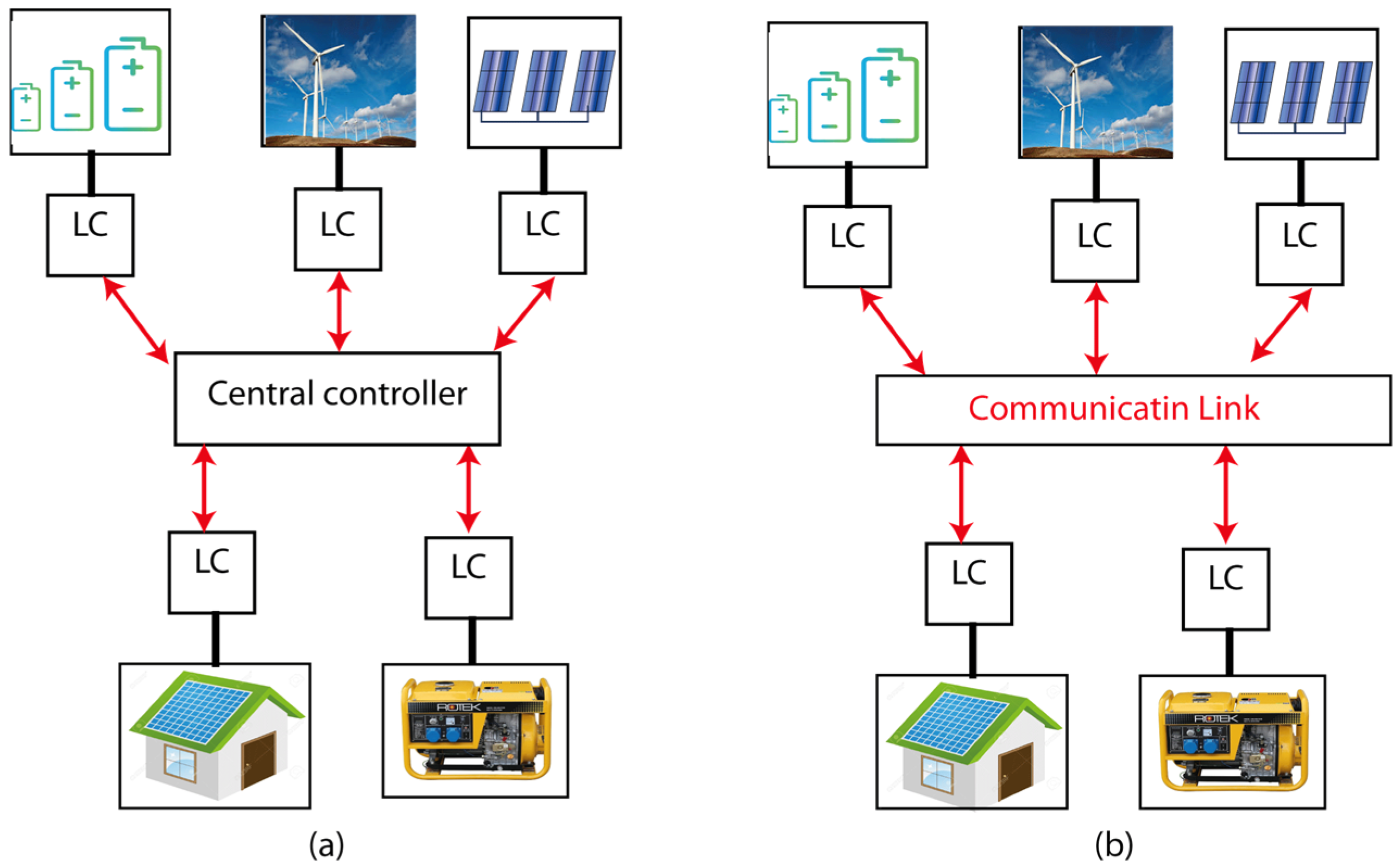
2. Overview of Local Control in Microgrids

Microgrids’ control purposes are to maintain stable system operation, regulate low voltage, and equalize load sharing among distributed generators per unit under steady-state conditions (DGs). Local control is a good energy management technique in a hybrid microgrid. In low-voltage microgrid applications, however, nominal voltage reference offsets and unequal connecting cable resistances will require a trade-off between voltage regulation and load sharing.
Classically, various control methods have been used to control microgrids, such as PI/PID linear control, fuzzy logic, and artificial neural network control. This section provides an overview of the control techniques used for energy management, voltage, and frequency control in the microgrid used in this paper.

2.1. Proportional–Integral–Derivative (PID) Technique

PID control is a broad feedback control technique commonly used in the automatic controllers of industrial control systems. PID controllers are the most widely used methods for engineering application controls, and they transform the error signal into an input signal using a proportional factor (P), integrative action (I), and differential action (D) [20]. The error signal, which reflects the PID controller’s input, is obtained by comparing the measured output signal with its desired reference. The error signal is processed by the PID controllers in order to reduce it. The authors of [21] propose employing a PI controller in a hybrid vehicle to recover regenerative braking energy while charging the battery and keeping the electric vehicle’s voltage bus constant. A comparison of the responses of PI and PID-controlled bidirectional DC–DC converter systems is also included in [22]. The PID controller must automatically regulate power disruption or load variation effects, as shown in the example in [23]. The parameters in this controller are chosen via trial and error or other strategies, such as those proposed by Ziegler and Nicholas. PID/PI is strong, safe, and provides near-optimal control system performance with the suitable tuning of gains. However, for nonlinear and complicated systems, the PI/PID tuning strategies have limited ability to tune the PID additions appropriately. The PID performance is heavily reliant on the appropriate circumstances of the PID parameters inside this framework [24].

2.2. Neural Networks for Microgrid Control

An artificial neural network (ANN) control technique has recently been employed for microgrid control—notably, voltage and frequency regulation—in a variety of applications [25], including the management of power equipment such as inverters and bi-direction inverters in AC microgrids. ANN controllers have proven to display a rapid response time and a high level of stability and reliability. It has the potential to increase an AC microgrid’s frequency and voltage stability, as well as power quality, and to ensure rapid transitions between modes [26]. However, no study has been carried out using ANNs to control DC/DC converters or to use ANNs to govern DC microgrids. In [27], a preliminary investigation was published on creating an ANN-based DC/DC converter control system and combining it with a droop mechanism to regulate a freestanding DC microgrid. The wind speed was estimated in real time using a back-propagation ANN in [28]. In [29], a discrete-time NN controller for controlling the DC distribution system is proposed. An updated Elman neural network (ANN) and a radial Basis function network (RBFN) are presented as MPPT controllers for various types of RES in [30].
To address the uncertainties of DC–DC converters (DDCs), Kazemlou and Mehraeen [31] present a decentralized NN controller, which integrates the scattered sources of a DC grid and stabilizes the output voltage in the event of a disturbance. Low-inertia distribution systems are given special attention, such as solar panels connected to the DC bus via a buck converter. To maintain stability, the suggested controller uses an adaptive approach to change the duty cycle; input and output voltages and currents must be measurable, but communication between the converters is not required. Two NNs at the front-end converter in [32] manage the DC-bus voltage as well as the active and reactive power flows.

2.3. Fuzzy Logic in Power Systems

Fuzzy control is based on fuzzy logic, which resembles human reasoning and natural language significantly more closely than classic analytical systems [33].
Fuzzy logic is now used in practically every industry, science, and power grid. Frequency regulations in microgrids is one such application. The fundamental goal of frequency management in microgrid systems is to maintain the balance between output and consumption. Due to their durability and reliability, fuzzy controllers effectively address a wide range of control challenges. Fuzzy logic is similar to human logic and outperforms PID controllers. In nonlinear systems, fuzzy control is more adaptive than typical PID controllers and has a shorter settling time [34].
In addition, fuzzy logic control (FLC) has been used to create an energy management system (EMS). In addition to EMSs for stand-alone microgrids [35,36] proposes EMSs for a DC microgrid based on a fuzzy logic controller. The proposed FLC prioritizes selling additional electricity generated by renewable energy sources (RES) while keeping the battery state of charge (SOC) above 50% to extend battery life. This heuristic knowledge advises using fuzzy logic control to create the EMS for the circumstance under examination. This technique effortlessly combines the user’s experience rather than employing a mathematical model of the system. Furthermore, an improved EMS design based on FLC was shown [37].
The advantages and disadvantages of various control strategies are given in Table 1 [38].

3. Microgrid Modeling

The studied autonomous hybrid microgrid comprises two renewable energy sources (photovoltaic and wind), battery energy storage as backup source, and loads. Microgrids can be connected to the main grid via a common coupling point (CCP).

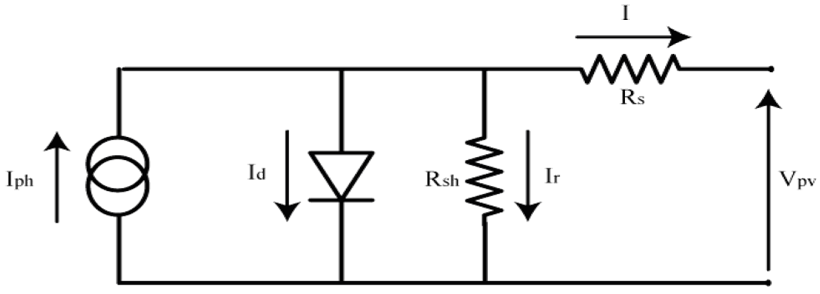
3.1. Photovoltaic System

As shown in Figure 3, the photovoltaic system consisted of a photovoltaic panel, a boost converter, and a maximum power point tracking (MPPT) controller.
A photovoltaic cell is an electronic component that generates electricity by exposing it to sunlight. The cell can be used on its own or in a photovoltaic panel with other solar cells. There are several PV cell models available, each with its own level of complexity and precision. Photovoltaic cells can be modeled by the equivalent electrical circuit given in Figure 4.
The following equation models the current of the PV cell:
I d = I p h I 0 ( e x p V p v + R s   I V T 1 ) V p v + R s   I R s h
V T = N s   n   k   T q
VT: The thermal voltage;
Ns: Cells connected in series;
n: The diode ideality constant;
q: Charge of the electron;
k: The Boltzmann constant;
T: The temperature of the p–n junction;
Iph: The photo-current;
I0: Reverse saturation currents of the diode.
As a reference module, we used a MATLAB/Simulink-implemented PV model (Sun Power SPR-250NX-BLK-D). The 250 W module was chosen to make the calculation easier. The properties of this PV model are listed in Table 2.
A static converter (DC/DC power converter) is used as an adapter between PV generators and the load to collect the maximum power produced and transfer it to the load. The boost converter is controlled by an MPPT (maximum power point tracking) controller to offer maximum power efficiency at all times. They perturb and observe (P&O) [39] method is used in this paper. To acquire the highest power delivered by the PV, this program employs an iterative strategy based on an algorithmic process, as shown in Figure 5.

3.2. Wind Turbine System

Wind energy systems (WESs) are the most readily available and promising source of electrical energy. The kinetic energy of the wind is used to spin turbines, which provide mechanical energy. Generators transform mechanical energy into electrical energy. As a result, wind energy is generated in a linear connection with wind speed. The MPPT control unit works based on following the maximum power point for each wind speed [40]. A wind turbine’s optimum power is distinctively nonlinear and bell-shaped. The system looks for the maximum power for each wind speed, analogously to looking for the best rotational speed. The power is plotted as a function of the rotating speed of the turbine. There is only one setting for each wind speed which enables the maximum power to be obtained.
As illustrated in Figure 6, the wind generator comprises a wind turbine, a synchronous permanent magnet generator, and a power converter controlled by an MPPT.

3.3. Battery Energy Storage Systems (BESSs)

When solar sources are insufficient to satisfy load demand, the battery energy storage system (BESS) is used as a backup power source and as a load to keep the system balanced when there is excess electricity. As shown in Figure 7, the BESS comprises a Li-ion battery, a bidirectional DC–DC converter, and a controller that manages the battery’s charging and discharging to maintain the microgrid bus balance. Due to the nonlinearity of the voltage response, lithium-ion batteries are difficult to predict. In this research, the dynamic battery model from Simulink’s SimPowerSystems package is used.
Bidirectional DC/DC inverters allow electricity to be transported between the battery and the microgrid. Due to their capacity to reverse the direction of current flow while maintaining an unchanged voltage polarity at either end, they are increasingly being employed as connections between the battery and the microgrid system to regulate battery charging and draining; as illustrated in Figure 8, the bidirectional employed in this study was a half-bridge IGBT topology that runs in continuous conduction mode. When surplus energy is stored at the DC bus, the converter is in boost mode; otherwise, it is in buck mode. Current flows to the DC bus because S2 and D1 are in boost mode. In buck mode, S1 and D2 are engaged, and power is supplied to the battery.

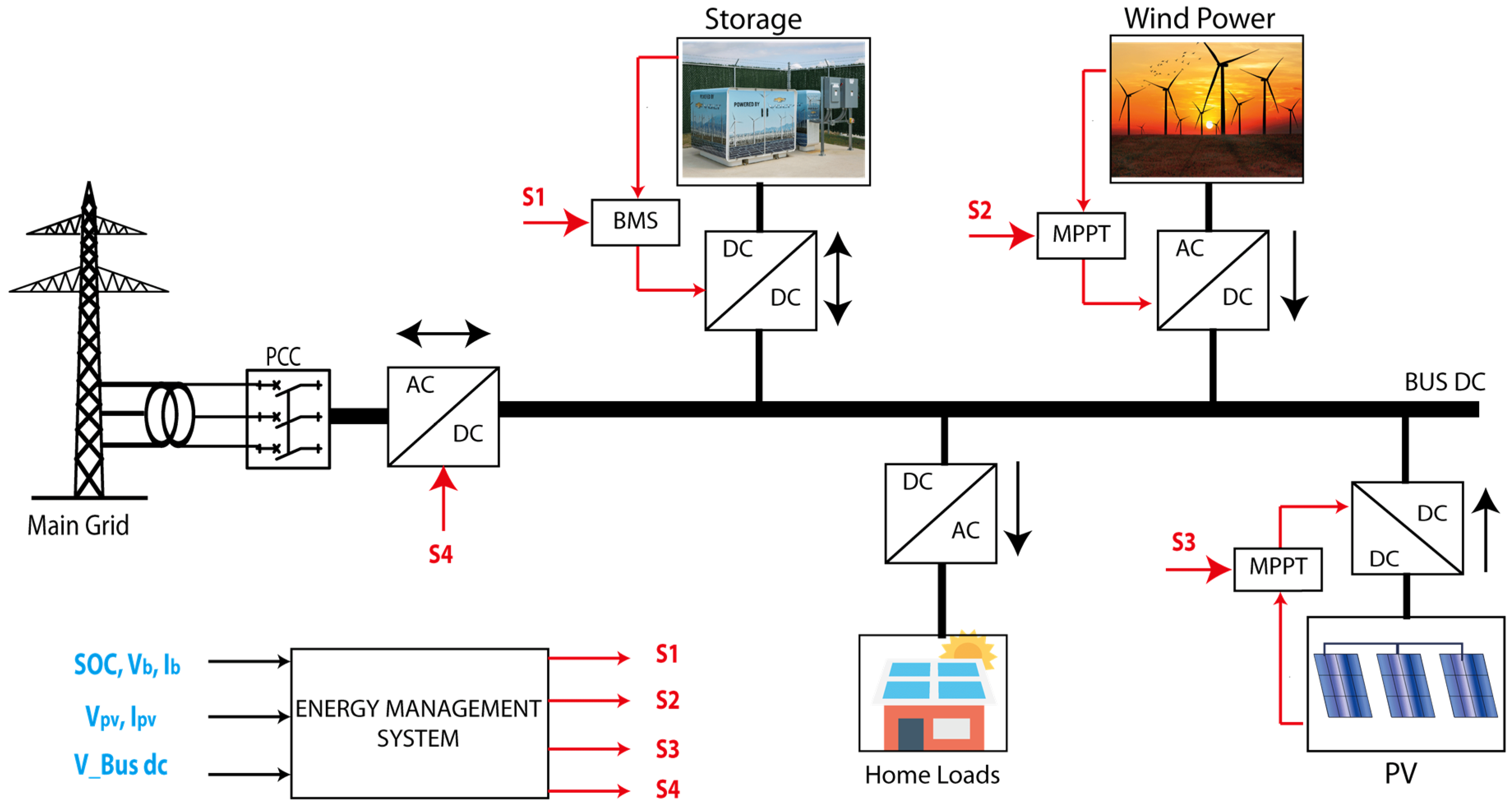
3.4. Energy Management System (EMS)

The proposed technique for microgrid management consisted of three intelligence methods (PID, fuzzy logic, and ANN). The used microgrid was composed of multiple power sources, as shown in Figure 8:
  • To extract the greatest power from the photovoltaic solar system, it is connected to the DC bus via a DC/DC converter controlled by an MPPT block;
  • To draw the most power from a wind turbine, multiple converters and an MPPT block are used to link it to the DC bus;
  • The battery system is connected to the microgrid via BDC, and several controllers are used to operate it (PID, ANNC, and FL);
  • The main grid, connected to the DC bus via an AC/DC converter, will only be used in an emergency (when renewable energy is insufficient), and the battery state of charge is less than 20%.
The main objects of the proposed energy management are:
  • To supply the energy demand;
  • To increase the renewable energy produced;
  • To maintain the microgrid bus’s balance, keep the DC bus’s voltage constant at 300 V and the AC bus’s frequency constant at 50 Hz;
  • To avoid overcharging or discharging of the battery.
The EMS strategy provides a control signal for each element in the microgrid, making each component have its controller independently of other sources (decentralized controller). The flowchart in Figure 9 shows the energy management strategy applied in this work.
The operational modes of the microgrid-defined energy management system are shown in Figure 9. These operating modes should take into account the various modes of power produced, the battery state of charge (charging/discharging), and the load consumption. As a result, based on the battery’s SoC, the power flow inside the system can be divided into three operational scenarios. To improve the battery lifecycle, physical conditions must be used. The state of charge of the battery must be within a lower limit and an upper limit ( 20 % < S O C < 80 % ). The power sources P R E S   operates in the MPPT mode to charge the battery and to satisfy the load demand P L o a d .
In charging mode ( P R E S > P L o a d ), when the power produced from PV and wind sources is more than the load demand, the battery absorbs the excess power in the DC bus to regulate the voltage and frequency of the microgrid.
In the event that the power source module is unable to meet the load requirement ( P R E S < P L o a d ), the battery can assist in meeting the need.

4. Control Design for the Microgrid

This section presents the design of the controller systems developed in this paper for energy management and voltage control.

4.1. PID Controller Design

The most often utilized method for engineering application control is PID controllers. They use a proportional factor (P) and integrative action to turn error signals into input signals (I). When comparing the measured output signal with their intended references to obtain the error signal, which is the PID controller’s input, The PID controllers decrease the error signal.
The difference between the measured voltage (V-DC-Bus) and the desired voltage (V-reference) is amplified by the controller to produce the Error signal (e).
The bidirectional converter keeps the voltage fixed at 300 V and balances between load production and consumption. In this study, we performed a simulation. The control strategy used in this system is shown in Figure 10. The bidirectional converter was voltage-controlled; therefore, the DC_BUS voltage was measured and compared with the reference voltage. The difference between these voltage values was processed in PID blocks and generated the duty cycle of each direction. The suggested battery charger algorithm generated the duty cycle value for controlling the system converter using a PWM signal based on the voltage and battery state of charge measured at the DC bus.
The controller output altered the PWM signal to reduce inaccuracy by changing the power-sharing via a DC–DC bidirectional converter between the battery and microgrid. The reference model (300 V) was chosen to provide a response which is optimal and similar to the reference input.
The output of the PID controller can be expressed as [40]:
u ( s ) = K p   e ( s ) + K I S   e ( s ) + K D . S . e ( s )
T The transfer function can be written as follows:
H ( s ) = u ( s ) e ( s ) = K p + K I S + K D . S
where e ( s ) = | V r e f V D C | .
The propositional gain (Kp) will minimize the rising time, but not the steady-state error. Although the integral gain (KI) eliminates the steady-state error, it may exacerbate the sudden response. The derivative gain (KD) will improve the transient responsiveness by boosting system stability, lowering overshoot, and minimizing overshoot. S is the Laplace operator.

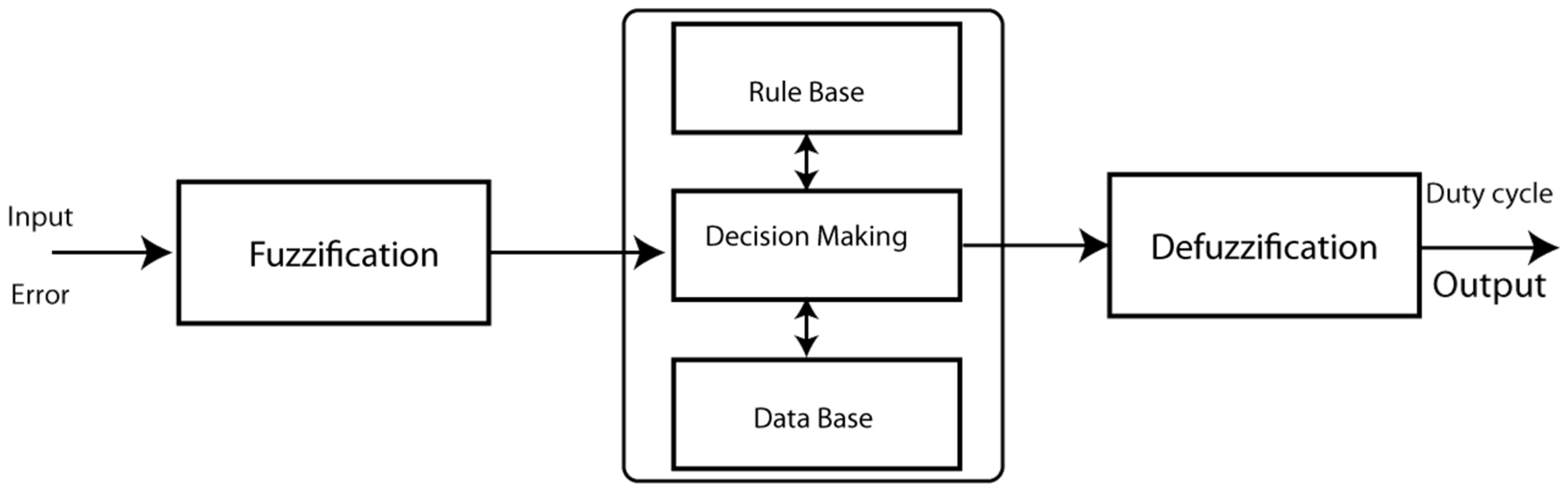
4.2. Fuzzy Logic Controller Design

In a variety of difficult fields, fuzzy logic control (FLC) is widely used. FLC is regarded as one of the most intelligently shot solutions to distributed power optimization issues. FLC functions have been studied in depth to provide more capability in dealing with expert system issues. The development of a fuzzy logic controller for integration into the microgrid was based on the Fuzzy Logic toolbox from MATLAB/Simulink.
The partial matching capacity of fuzzy rule reasoning is a key characteristic, because it allows inference from fuzzy rules even when their conditions are only partially met. Figure 11 shows a block diagram of the fuzzy logic controller [41,42].
The FLC is made up of three parts: fuzzification, fuzzy inference system, and defuzzification. A fuzzy set is used to express a fuzzy variable which is defined by a membership function in general. Fuzzification is the process of converting a crisp input into a linguistic variable. Fuzzification is a task that requires expertise. Membership functions are triangle-shaped or trapezoidal-shaped. The inference is the following block, which is a rule-based task based on expert knowledge. Defuzzification returns a crisp value to the linguistic variable.
In this paper, the membership functions for input error used for microgrid control are presented in Figure 12.
We have considered three Linguistic variables (Negative, Positive, Right) for the Input ‘Error’, and for the output Control, we have considered three Linguistic variables (Up, down, and no change), as shown in Figure 13.
The fuzzy controller generated an appropriate switching pattern for the charging and draining of the battery. When the DC bus voltage and a reference voltage were compared, the fuzzy logic controller received four inputs. As seen in Figure 13, it supplies the duty cycle for the PWM block to deliver the signal to the buck/boost converter.

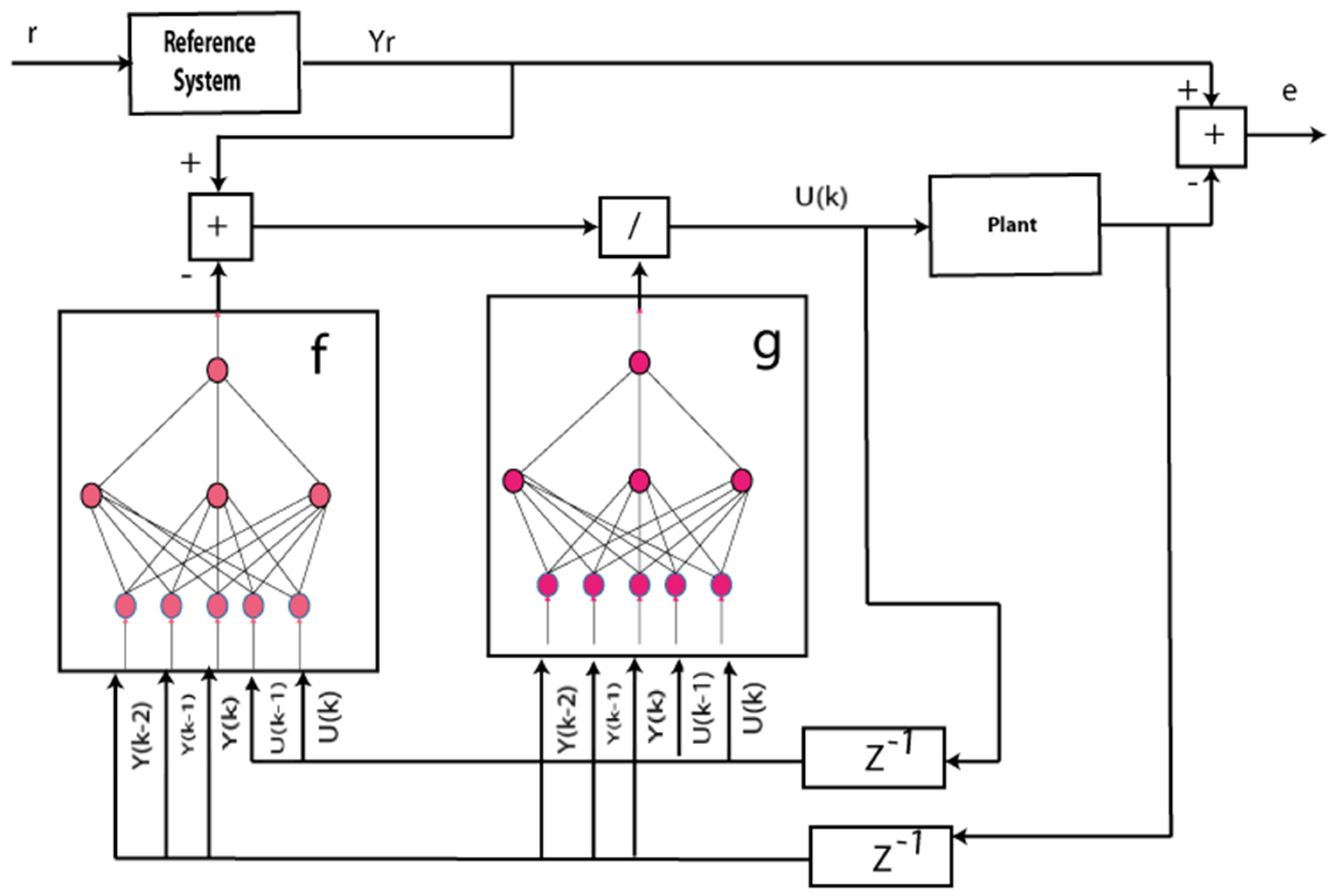
4.3. ANN Controller Design

With considerable success, the artificial neural network controller (ANNC) has been employed to control engineering applications. This sort of control’s primary goal is to linearize nonlinear dynamics. Two neural networks make up the NARMA L2 controllers: the first is the NARMA model, which represents broad discrete-time nonlinear systems in system identification; the second is for the control design, as shown in Figure 14.
Therefore, using the NARMA-L2 model, we can obtain the following controller:
u ( k + 1 ) = Y ( k + d ) f [ y ( k ) , , y ( k n + 1 ) , u ( k ) , , u ( k n + 1 ) ] g [ y ( k ) , , y ( k n + 1 ) , u ( k ) , , u ( k n + 1 ) ]
This paper utilized the ANC to manage the bidirectional DC–DC converter by producing the duty cycle for the PWM to keep the DC bus voltage constant at the reference voltage value. As a result, the reference, DC bus voltage, and duty cycle values on the output were the ANC’s inputs. To create a database for ANNC, numerous tests were conducted. The approach measured the DC bus and duty cycle voltages while simulating various irradiation and load power values.

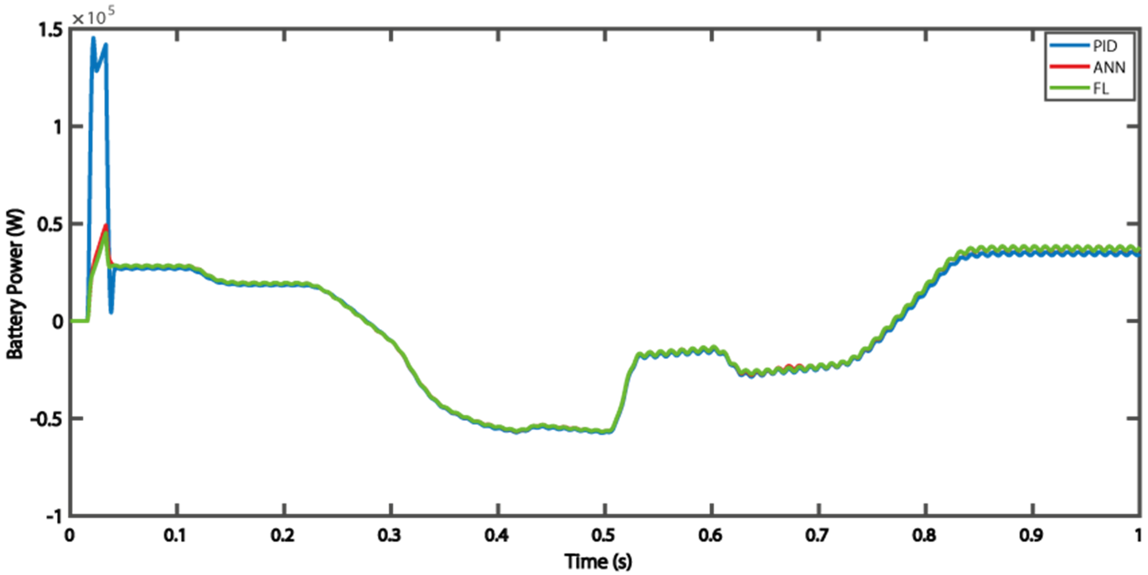
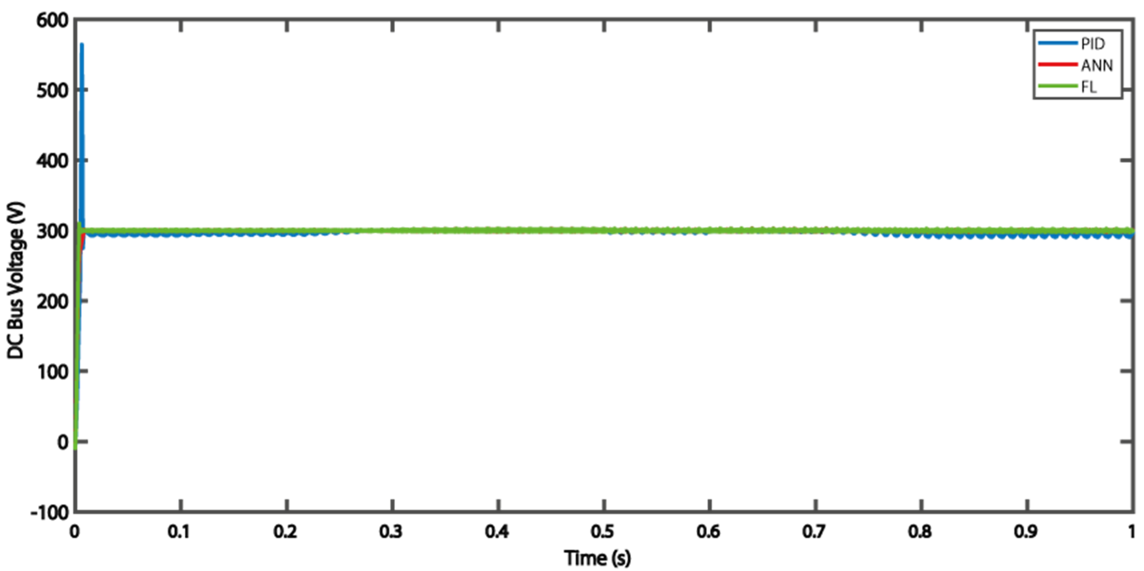
5. Simulation and Results

The hybrid microgrid system (Figure 15) is composed of hybrid DC and AC sources. To extract the most power from each renewable source, each power source is connected to the microgrid’s DC bus via a power converter. The solar cell type is Sunpower SPR 250 NX-BLK with 49 panels in series and 11 in parallel to provide a full power of 65 KW. The wind turbine type is PMSG and provides a maximum power of 20 KW. The battery type is Li-ion, capacity = 280 Ah, and voltage V = 200 V. The load demands in DC Bus is P = 10 KW and V = 300 V. The loads required in AC Bus are P = 20 KW between t = 0 s and 0.5 s and P = 60 KW between t = 0.5 and t = 1 s.
The simulation runs for one second with a 1 × 10⁻⁵ sampling rate to compare the reaction of the proposed energy management method with each controller in the microgrid balance during changes in weather conditions. The results of interface monitoring show how each piece reacts to the numerous adjustments.
Figure 16 and Figure 17 show the variation of the produced power from PV panels and wind turbines within the proposed meteorological scenario.
At the beginning of the simulation between t = 0 s and t = 0.3 s, the sum of the power produced from the renewable sources was less than 30 KW (DC and AC loads demanded). The maximum PV power produced was about 10 KW, and the wind power was about 1 KW. This means that the battery discharged to provide energy for the microgrid to maintain the power balance and provide power for both loads because the battery’s state of charge (SOC) was limited to 20% < SOC < 80%. The decline in the state of charge curve and the battery power of 35 KW, as illustrated in Figure 18 and Figure 19, indicates that the battery provided energy in the range of 34 KW. Therefore, the power needs problem in the DC bus was solved. In addition, between t = 0.3 s and t = 0.5 s, the solar eyes increased more than 35 KW, and the wind power increased to 10 KW, which means that there was an energy surplus and the system became unbalanced. As we already described, the battery is the main element for the system balance. Due to the battery state of charge in its safe zone, the battery stored the surplus to balance the power production and consumption.
At t = 0.5 s, the power demand of the AC bus increased to 70 KW. The solar power at this time equaled its maximum value of 70 KW, and the wind turbine equaled 10 KW. Therefore, the surplus of energy stored in the battery was reduced compared with the previous interval, and the slope of charging decreased, as shown in Figure 17 and Figure 18.
At t = 0.6, the irradiation value decreased again, decreasing the primary source (solar system). At t = 0.8 s, the sum of renewable sources became less than the loads demanded, which means that the battery will be discharged again to provide the surplus power of the microgrid. Notably, the difference between produced and requested power increases, which means that the power supplied by the battery increased linearly with this difference.
As stated at the outset, the goal of this study was to balance the amount of energy in microgrid systems while also regulating the voltage and frequency on the DC and AC buses. Figure 20 and Figure 21 depict the measured values of power and voltage in the DC bus, respectively, whereas Figure 22 depicts the frequency variation of the AC bus.
The power measured in the AC and DC bus shows that the DC load consumed 10 KW, and the AC load consumed 20 KW between t = 0 s and t = 0.5 s, and 60 KW between t = 0.5 s to t = 1 s; the voltage of the DC bus was stable at 300 V, as already requested at the beginning of the simulation. From Figure 19, Figure 20 and Figure 21, we can conclude the considerable advantages of artificial intelligence (ANN and FL) methods in stabilizing voltage and power at the reference value.
Figure 23 shows that the frequency variation of the three methods in the limit merges was ±0.02, except at the beginning of the simulation, which is called the transitory regime and was not considered. The minimum variation in the frequency corresponded to the fuzzy logic response. Therefore, we conclude the efficiency of fuzzy logic controllers in the stability of microgrid voltage power and frequency from comparing the three controllers. The simulation results explain the effectiveness and robustness of the proposed EMS in the face of all changes in meteorological conditions and load demand.

6. Conclusions

For the MGs controlled by the various smart approaches in this study, the researchers developed a novel distributed control architecture. The contribution of this study presents the design and development of three smart controllers’ methods for energy management in the microgrid. The controllers are designed for application to hybrid microgrids with battery energy system control to enhance the MG voltage and frequency under different system load operations and different solar irradiation. The proposed methodologies’ performance was evaluated, utilizing a variety of load dynamics in various scenarios dependent on metrology circumstances. The obtained results using the proposed controllers guarantee the safe operation and high stability of the microgrid. The simulation results also showed that the fuzzy logic controller is better than the others (PID and ANN) in terms of efficiency and precision. Future work related to this topic includes:
  • Hardware implementation of the three methods (PID, ANN, and FL) to validate the performance in experimental processes;
  • The integration of energy optimization (electricity, price, and CO2 emissions) in global management of the energy management system.

Author Contributions

Conceptualization, K.A.A.S., N.S., N.I.A.W. and H.H.; methodology, K.A.A.S., N.S., N.I.A.W. and H.H.; software, K.A.A.S., N.S., N.I.A.W. and H.H.; validation, N.S., N.I.A.W. and H.H.; formal analysis, K.A.A.S., N.S., N.I.A.W. and H.H.; investigation, K.A.A.S., N.S., N.I.A.W. and H.H.; resources, K.A.A.S., N.S., N.I.A.W. and H.H.; data curation, K.A.A.S.; writing—original draft preparation, K.A.A.S.; writing—review and editing, K.A.A.S., N.S.; visualization, K.A.A.S., N.S.; supervision, N.S., N.I.A.W. and H.H.; project administration, K.A.A.S., N.S. and N.I.A.W. All authors have read and agreed to the published version of the manuscript.

Funding

This research received no external funding.

Institutional Review Board Statement

Not applicable.

Informed Consent Statement

Not applicable.

Data Availability Statement

Not applicable.

Acknowledgments

This work supported by the University Putra Malaysia.

Conflicts of Interest

The authors declare no conflict of interest.

Abbreviations

ANNArtificial neural network
BESSBattery energy storage system
CCPCommon coupling point
CCCentral controller
DGDistributed generation
ESSEnergy storage system
EMSEnergy management system
FLFuzzy logic
LCLocal controller
MGMicrogrid
MPPTMaximum power point tracking
RESRenewable energy resource
RBFNRadial basis function network
PIDProportional-integral-derivative
PVPhotovoltaic
PWMPulsewidth modulation
SOCState of charge

References

  1. Molina, M.G. Energy storage and power electronics technologies: A strong combination to empower the transformation to the smart grid. Proc. IEEE 2017, 105, 2191–2219. [Google Scholar] [CrossRef]
  2. Justo, J.J.; Mwasilu, F.; Lee, J.; Jung, J.W. AC-microgrids versus DC-microgrids with distributed energy resources: A review. Renew. Sustain. Energy Rev. 2013, 24, 387–405. [Google Scholar] [CrossRef]
  3. Sen, S.; Kumar, V. Microgrid control: A comprehensive survey. Annu. Rev. Control 2018, 45, 118–151. [Google Scholar] [CrossRef]
  4. Wei, X.; Xiangning, X.; Pengwei, C. Overview of key microgrid technologies. Int. Trans. Electr. Energy Syst. 2018, 28, e2566. [Google Scholar] [CrossRef]
  5. Yazdanian, M.; Mehrizi-Sani, A. Distributed control techniques in microgrids. IEEE Trans. Smart Grid 2014, 5, 2901–2909. [Google Scholar] [CrossRef]
  6. Roslan, M.F.; Hannan, M.A.; Ker, P.J.; Uddin, M.N. Microgrid control methods toward achieving sustainable energy management. Appl. Energy 2019, 240, 583–607. [Google Scholar] [CrossRef]
  7. Mahmoud, M.S.; Hussain, S.A.; Abido, M.A. Modeling and control of microgrid: An overview. J. Frankl. Inst. 2014, 351, 2822–2859. [Google Scholar] [CrossRef]
  8. Lede, A.M.R.; Molina, M.G.; Martinez, M.; Mercado, P.E. Microgrid architectures for distributed generation: A brief review. In Proceedings of the 2017 IEEE PES Innovative Smart Grid Technologies Conference-Latin America (ISGT Latin America), Quito, Ecuador, 20–22 September 2017; pp. 1–6. [Google Scholar]
  9. Palizban, O.; Kauhaniemi, K.; Guerrero, J.M. Microgrids in active network management—Part II: System operation, power quality and protection. Renew. Sustain. Energy Rev. 2014, 36, 440–451. [Google Scholar] [CrossRef] [Green Version]
  10. Azeroual, M.; Lamhamdi, T.; El Moussaoui, H.; El Markhi, H. Simulation tools for a smart grid and energy management for microgrid with wind power using multi-agent system. Wind. Eng. 2020, 44, 661–672. [Google Scholar] [CrossRef]
  11. Mazidi, M.; Rezaei, N.; Ardakani, F.J.; Mohiti, M.; Guerrero, J.M. A hierarchical energy management system for islanded multi-microgrid clusters considering frequency security constraints. Int. J. Electr. Power Energy Syst. 2020, 121, 106134. [Google Scholar] [CrossRef]
  12. Tsikalakis, A.G.; Hatziargyriou, N.D. Centralized control for optimizing microgrids operation. In Proceedings of the 2011 IEEE Power and Energy Society General Meeting, Detroit, MI, USA, 24–29 July 2011; pp. 1–8. [Google Scholar]
  13. Khorsandi, A.; Ashourloo, M.; Mokhtari, H. A decentralized control method for a low-voltage DC microgrid. IEEE Trans. Energy Convers. 2014, 29, 793–801. [Google Scholar] [CrossRef]
  14. Li, Y.; Sun, Z.; Han, L.; Mei, N. Fuzzy comprehensive evaluation method for energy management systems based on an Internet of Things. IEEE Access 2017, 5, 21312–21322. [Google Scholar] [CrossRef]
  15. Leonori, S.; Martino, A.; Mascioli, F.M.F.; Rizzi, A. Microgrid energy management systems design by computational intelligence techniques. Appl. Energy 2020, 277, 115524. [Google Scholar] [CrossRef]
  16. Ding, Z.; Hu, T.; Li, M.; Xu, X.; Zou, P.X. Agent-based model for simulating building energy management in student residences. Energy Build. 2019, 198, 11–27. [Google Scholar] [CrossRef]
  17. Mobashsher, M.M.; Keypour, R.; Savaghebi, M. Distributed optimal voltage control in islanded microgrids. Int. Trans. Electr. Energy Syst. 2021, 31, e13045. [Google Scholar] [CrossRef]
  18. Barik, A.K.; Das, D.C.; Latif, A.; Hussain, S.M.; Ustun, T.S. Optimal Voltage–Frequency Regulation in Distributed Sustainable Energy-Based Hybrid Microgrids with Integrated Resource Planning. Energies 2021, 14, 2735. [Google Scholar] [CrossRef]
  19. Arfeen, Z.A.; Khairuddin, A.B.; Larik, R.M.; Saeed, M.S. Control of distributed generation systems for microgrid applications: A technological review. Int. Trans. Electr. Energy Syst. 2019, 29, e12072. [Google Scholar] [CrossRef] [Green Version]
  20. Abdolrasol, M.G.M.; Hannan, M.A.; Hussain, S.M.; Ustun, T.S.; Sarker, M.R.; Ker, P.J. Energy Management Scheduling for Microgrids in the Virtual Power Plant System Using Artificial Neural Networks. Energies 2021, 14, 6507. [Google Scholar] [CrossRef]
  21. Kasimalla, V.K.; Velisala, V. A review on energy allocation of fuel cell/battery/ultracapacitor for hybrid electric vehicles. Int. J. Energy Res. 2018, 42, 4263–4283. [Google Scholar] [CrossRef]
  22. Ramya, K.C.; Jegathesan, V. Comparison of pi and PID controlled bidirectional dc-dc converter systems. Int. J. Power Electron. Drive Syst. 2016, 7, 56. [Google Scholar] [CrossRef] [Green Version]
  23. Chen, Z.; Yuan, X.; Ji, B.; Wang, P.; Tian, H. Design of a fractional order PID controller for hydraulic turbine regulating system using chaotic non-dominated sorting genetic algorithm II. Energy Convers. Manag. 2014, 84, 390–404. [Google Scholar] [CrossRef]
  24. Wang, L.; Liu, J.; Yang, C.; Wu, D. A novel interval dynamic reliability computation approach for the risk evaluation of vibration active control systems based on PID controllers. Appl. Math. Model. 2021, 92, 422–446. [Google Scholar] [CrossRef]
  25. Bakar, N.N.A.; Hassan, M.Y.; Sulaima, M.F.; Na’im Mohd Nasir, M.; Khamis, A. Microgrid and load shedding scheme during islanded mode: A review. Renew. Sustain. Energy Rev. 2017, 71, 161–169. [Google Scholar] [CrossRef]
  26. Boujoudar, Y.; Azeroual, M.; El Moussaoui, H.; Lamhamdi, T. Intelligent controller based energy management for stand-alone power system using artificial neural network. Int. Trans. Electr. Energy Syst. 2020, 30, e12579. [Google Scholar] [CrossRef]
  27. Albarakati, A.J.; Boujoudar, Y.; Azeroual, M.; Jabeur, R.; Aljarbouh, A.; El Moussaoui, H.; Ouaaline, N. Real-Time Energy Management for DC Microgrids Using Artificial Intelligence. Energies 2021, 14, 5307. [Google Scholar] [CrossRef]
  28. Hernández, L.; Baladrón, C.; Aguiar, J.M.; Carro, B.; Sánchez-Esguevillas, A.; Lloret, J. Artificial neural networks for short-term load forecasting in microgrids environment. Energy 2014, 75, 252–264. [Google Scholar] [CrossRef]
  29. Chettibi, N.; Mellit, A.; Sulligoi, G.; Pavan, A.M. Adaptive neural network-based control of a hybrid AC/DC microgrid. IEEE Trans. Smart Grid 2016, 9, 1667–1679. [Google Scholar] [CrossRef] [Green Version]
  30. Rezvani, A.; Esmaeily, A.; Etaati, H.; Mohammadinodoushan, M. Intelligent hybrid power generation system using new hybrid fuzzy-neural for photovoltaic system and RBFNSM for wind turbine in the grid connected mode. Front. Energy 2019, 13, 131–148. [Google Scholar] [CrossRef]
  31. Kazemlou, S.; Mehraeen, S. Decentralized discrete-time adaptive neural network control of interconnected DC distribution system. IEEE Trans. Smart Grid 2014, 5, 2496–2507. [Google Scholar] [CrossRef]
  32. Lopez-Garcia, T.B.; Coronado-Mendoza, A.; Domínguez-Navarro, J.A. Artificial neural networks in microgrids: A review. Eng. Appl. Artif. Intell. 2020, 95, 103894. [Google Scholar] [CrossRef]
  33. Kala, H.; Deepakraj, D.; Gopalakrishnan, P.; Vengadesan, P.; Iyyar, M.K. Performance evaluation of fuzzy logic and PID controller for liquid level process. Perform. Eval. 2014, 2, 1311–1314. [Google Scholar]
  34. Ray, P.K.; Paital, S.R.; Mohanty, A.; Eddy, F.Y.; Gooi, H.B. A robust power system stabilizer for enhancement of stability in power system using adaptive fuzzy sliding mode control. Appl. Soft. Comput. 2018, 73, 471–481. [Google Scholar] [CrossRef]
  35. Vivas, F.J.; Segura, F.; Andújar, J.M.; Palacio, A.; Saenz, J.L.; Isorna, F.; López, E. Multi-objective fuzzy logic-based energy management system for microgrids with battery and hydrogen energy storage system. Electronics 2020, 9, 1074. [Google Scholar] [CrossRef]
  36. Rodriguez, M.; Arcos-Aviles, D.; Llanos, J.; Salazar, A.; Guinjoan, F.; Motoasca, E.; Martinez, W. Fuzzy-based energy management system for isolated microgrids using generation and demand forecast. In Proceedings of the 2021 23rd European Conference on Power Electronics and Applications (EPE’21 ECCE Europe), Online, 3–7 May 2021; pp. 1–10. [Google Scholar]
  37. Arcos-Aviles, D.; Pascual, J.; Marroyo, L.; Sanchis, P.; Guinjoan, F. Fuzzy logic-based energy management system design for residential grid-connected microgrids. IEEE Trans. Smart Grid 2016, 9, 530–543. [Google Scholar] [CrossRef] [Green Version]
  38. Elmouatamid, A.; Ouladsine, R.; Bakhouya, M.; El Kamoun, N.; Khaidar, M.; Zine-Dine, K. Review of Control and Energy Management Approaches in Micro-Grid Systems. Energies 2021, 14, 168. [Google Scholar] [CrossRef]
  39. Mousa, H.H.; Youssef, A.R.; Mohamed, E.E. State of the art perturb and observe MPPT algorithms-based wind energy conversion systems: A technology review. Int. J. Electr. Power Energy Syst. 2021, 126, 106598. [Google Scholar] [CrossRef]
  40. Kushwaha, A.; Gopal, M.; Singh, B. Q-learning based maximum power extraction for wind energy conversion system with variable wind speed. IEEE Trans. Energy Convers. 2020, 35, 1160–1170. [Google Scholar] [CrossRef]
  41. Shi, Q.; Lam, H.K.; Xuan, C.; Chen, M. Adaptive neuro-fuzzy PID controller based on twin delayed deep deterministic policy gradient algorithm. Neurocomputing 2020, 402, 183–194. [Google Scholar] [CrossRef]
  42. Parikh, P.; Sheth, S.; Vasani, R.; Gohil, J.K. Implementing Fuzzy Logic Controller and PID Controller to a DC Encoder Motor—“A case of an Automated Guided Vehicle”. Proc. Manuf. 2018, 20, 219–226. [Google Scholar] [CrossRef]
Figure 1. Microgrid structure.
Energies 15 00303 g001
Figure 2. (a) Centralized and (b) decentralized control structure.
Energies 15 00303 g002
Figure 3. Photovoltaic system.
Energies 15 00303 g003
Figure 4. Equivalent electrical diagram of a photovoltaic cell.
Energies 15 00303 g004
Figure 5. Flowchart of MPPT algorithm.
Energies 15 00303 g005
Figure 6. Wind turbine system.
Energies 15 00303 g006
Figure 7. Battery system with a bi-directional inverter.
Energies 15 00303 g007
Figure 8. The proposed energy management system.
Energies 15 00303 g008
Figure 9. Flowchart of the energy management strategy.
Energies 15 00303 g009
Figure 10. Schema of the PID controller implementation.
Energies 15 00303 g010
Figure 11. Block diagram of the fuzzy control system.
Energies 15 00303 g011
Figure 12. Error signal membership functions.
Energies 15 00303 g012
Figure 13. Membership function for output.
Energies 15 00303 g013
Figure 14. NARMA-L2 Model plant.
Energies 15 00303 g014
Figure 15. Simulink file of the proposed EMS with multiple controllers.
Energies 15 00303 g015
Figure 16. The power produced from PV panels (W).
Energies 15 00303 g016
Figure 17. The power produced from wind turbines (W).
Energies 15 00303 g017
Figure 18. Variation in the battery state of charge (%).
Energies 15 00303 g018
Figure 19. Variation in battery power (W).
Energies 15 00303 g019
Figure 20. Measured voltage at the DC bus (V).
Energies 15 00303 g020
Figure 21. Measured power at the DC Bus (W).
Energies 15 00303 g021
Figure 22. Measured power at the AC bus (W).
Energies 15 00303 g022
Figure 23. Measured frequency at the AC bus (Hz).
Energies 15 00303 g023
Table 1. Brief comparison of control approaches.
TechniquesAdvantagesDisadvantages
PID Controller
  • Easy to implement;
  • Realization does not necessitate system dynamics;
  • Only three parameters to optimize.
  • Cannot ensure the resilience of PID closed-loop systems;
  • Cannot remove steady-state errors for sinusoidal signals;
  • Not adaptable to load variations.
  • Artificial neural networks Controller
  • In online or offline applications, the technique can control, optimize, and identify the system’s parameters;
  • Use nonlinear data techniques to solve challenges in large-scale systems in MGs;
  • Self-learning and prediction are used to solve the system’s stability and fault tolerance.
  • The model’s structure is complicated;
  • Difficult to determine the best network structure when adding or raising units from the MG topology (black boxes);
  • Difficult to determine the best network structure when adding or raising units from the MG topology;
  • Only possible if the system structure is stable.
  • Fuzzy logic Controller
  • Better voltage and frequency management, as well as power sharing between many MGs.
  • A high-quality processing unit is required;
  • Error methods are used for the participation function;
  • The procedure is time-consuming.
Table 2. Characteristics of (Sun Power SPR-250NX-BLK-D) PV model.
ParametersValues
Maximum power 250 W
Maximum power voltage42.8 V
Maximum power current5.84 A
Open circuit voltage 50.93 V
Current court-circuit6.2 A
Cellule numbers 72
Temperature coefficient of open-circuit voltage −0.29103%/°C
Temperature Coefficient of current court-circuit0.013306%/°C
Shunt resistance448.6949 ohms
Series resistance 0.37759
Publisher’s Note: MDPI stays neutral with regard to jurisdictional claims in published maps and institutional affiliations.

