1. Introduction
Ocean thermal energy conversion (OTEC) has huge potential to contribute not only by generating electricity but also by desalinating seawater and by utilizing deep ocean water for other industries for food self-sufficiency and sustainable economic development [
1]. Consequently, OTEC can contribute to a variety of sustainable development goals (SDGs) defined by United Nations and ratified in 2015. OTEC is a power generation system that uses surface water of around 30 °C and deep ocean water of around 5–10 °C as heat sources, and it converts the thermal energy stored as temperature differences into work. Accordingly, it can stably generate power 24 h a day, seven days a week, and it is not easily affected by sudden changes in weather. In OTEC, seawater has a key role as a heat source and heat sink, varying the temperature during the heat transfer process with the heat engine so, in principle, the effective temperature differences for heat engines are smaller than the temperature differences of heat sources. To increase the effective temperature difference of heat engines, Uehara et al. proposed a power generation system using a non-azeotropic mixed medium such as ammonia/water or a power generation system using a water cycle [
2] and verified the results using an experimental device [
3,
4,
5]. In addition, multi-stage power generation systems for multi-temperature-level utilization of heat engines have been theoretically estimated to increase the work from heat engines [
6,
7,
8,
9,
10,
11].
Generally, in conventional thermal power plants, thermodynamics using steam heat engines have been established.
Figure 1 shows the physical concept of the power generation system using a steam heat engine and the
T–
E diagram of conventional thermal power generation [
12,
13,
14].
T–
E diagram is easily understandable the energy conservation law in thermodynamics. For conventional thermal power generation, the combustion temperature of the boiler is significantly higher than the operating temperature of the heat engine (i.e., there is a massive temperature difference between the heat source and the heat engine). Hence, increasing the heat engine operating temperature (the turbine inlet temperature) is crucial to improve the thermal efficiency, and it is a reasonable approach, although, in general, the heat source turbine inlet temperature depends on the boiler material’s thermal resistance. The thermal efficiency,
ηth, is the ratio of the work of the heat engine,
W, to the input heat transfer rate to the heat engine,
Qin, as in the following expression:
In the case of the Carnot heat engine,
ηth is represented by the following expression:
On the other hand, the work from heat engines of OTEC is the product of the thermal efficiency of the heat engine and the heat transfer rate of the heat source. The thermal efficiency is approximately proportional to the effective temperature difference provided by heat engines, and the thermal energy is proportional to the temperature difference between the inlet and outlet of seawater as the heat source, but the effective temperature difference of the heat engine decreases when the heat transfer rate of the heat source is increased under the constant mass flow rate of the heat source. In finite-time thermodynamics (FTTs), considering the heat transfer process in the heat exchangers, the relation between the two factors of thermal efficiency and thermal energy implies the upper bound of the thermal efficiency at the maximum power output of the heat engine [
4,
5,
11,
15,
16,
17,
18,
19,
20,
21,
22,
23,
24,
25,
26,
27]. Ideally, the maximum values
Wm of the work of the Carnot heat engine, which is the ideal heat engine, and the thermal efficiency
ηth,CA at that time are expressed by the following equations [
15,
16,
17,
18,
19,
20,
21,
22,
23]:
Here, in the heat exchange process, when the heat transfer performance is infinite, ε = 1, assuming that the temperature of the seawater is constant (i.e., infinite seawater flow rate = 1). However, with conventional OTEC techniques, a finite amount of seawater is introduced into the heat engine in the power plant to generate electricity, so an increase in the seawater flow rate leads to a significant increase in seawater intake pumping power. Consequently, a change in the seawater temperature is inevitable, and cannot be set to infinite. It has also been shown that the work done with the Lorentz cycle, which is one of the ideal heat engines but which allows the temperature change of the heat source during heat exchange, is twice as much as that in Equation (3), but the thermal efficiency at that time is consistent with that in Equation (4).
Now, in principle, it should be recognized that the heat source of OTEC is the seawater temperature difference between surface seawater and deep seawater, not the thermal energy transferred to the heat engine from surface seawater. Additionally, the seawater thermal energy will vanish when both sections of the seawater become the equilibrium temperature. Therefore, the thermal energy leakage will be created by discharging seawater from the system. In addition, the available energy from the OTEC system must be discussed based on the equilibrium condition as the dead state. Without these concepts, there is no appropriate and effective performance evaluation of the OTEC system. However, the difference between the performance evaluation methods of conventional thermal power generation and the performance evaluation methods of OTEC is not recognized, and many current studies even mistakenly claim that the improvement of the thermal efficiencies of Equation (1) leads to the improvement of the performance of OTEC. Therefore, the aims of this study are, firstly, to summarize the conventional OTEC FTTs and proposes the thermal efficiency and exergy efficiency used in OTEC FTT as a basic concept as normalization for the step of a standardized performance evaluation method, and, secondly, to reevaluate the current designs of the reference OTEC data using these performance evaluation methods as a confirmation of the effectiveness.
In
Section 2, authors summarize the basic concept of OTEC FTT to reveal and introduce the transferable thermal energy performing normalization of thermal efficiency. The thermal energy recognizes the equilibrium state as a dead state in energy for the analysis of available energy using the most ideal heat engine in OTEC. In
Section 3, the proposed evaluation method of normalized thermal energy and exergy are applied to reevaluate the current designs by visualizing the effectiveness on the performance evaluation of OTEC. Finally, the authors summarize the research content in the conclusions in
Section 4.
2. Thermodynamics for OTEC
2.1. Energy Conservation (First Law of Thermodynamics)
In OTEC, the temperature difference between surface and deep seawater drives heat engines.
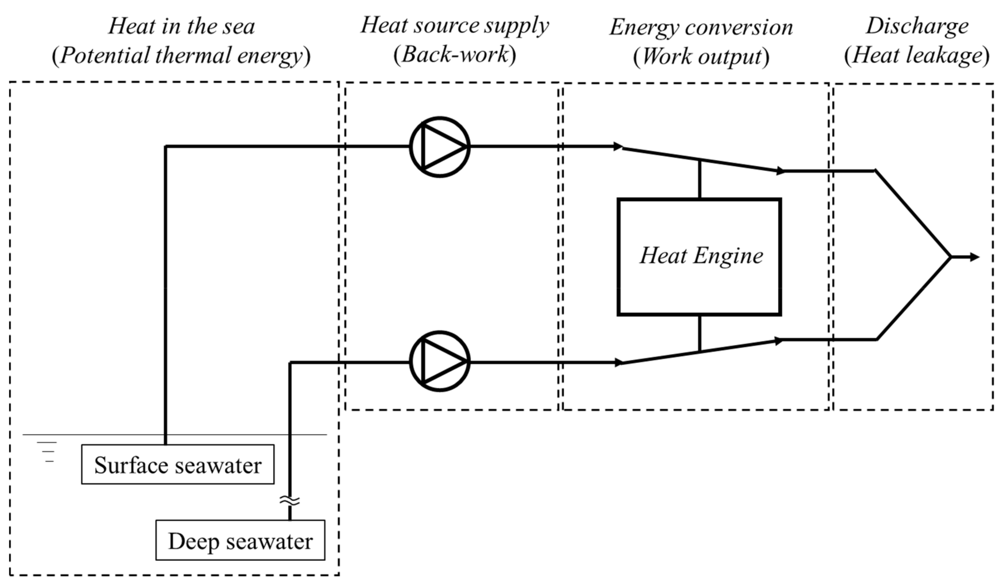
Figure 2 shows the conceptual process flow in OTEC power generation. The surface seawater and deep seawater are pumped by heat source supply pumps, heat exchange takes place with a heat engine, and then the energy is discharged. The current research assumes the adiabatic system in the process in
Figure 2. In OTEC, recognition and consideration of the heat in the sea and discharge process are very important and the introduction of those processes is the principle of the normalization in the evaluation of the performance, although, the power generation using a heat engine in conventional thermodynamics only focuses on the energy conversion and the heat source supply process in
Figure 2.
Focusing on the energy conversion process, the work of the heat engine,
W, is the balance of the heat transfer rate from the surface seawater
QW and the heat transfer rate to the deep seawater
QC:
where
m (kg/s) is the mass flow rate,
cp (kJ/(kgK)) is the specific heat at constant pressure,
U (kW/(kgK)) is the overall heat transfer coefficient of heat exchangers,
A (m
2) is the heat transfer area of heat exchangers, and Δ
Tm (K) is the logarithmic mean temperature difference. The subscripts of in, out,
W, and
C are inlet, outlet, warm surface seawater, and cold deep seawater, respectively.
The performance of the heat engine is evaluated using thermal efficiency, ηth, defined in Equation (1) as the ratio of available work from the heat engine, W, over the input heat transfer rate to the heat engine Qin. In general, we use Qin in the energy conversion process as a heat transfer rate from the heat source to the heat engine expressed by Equation (6). In the case of conventional power plants, the temperature difference between the combustion of fuel and the turbine inlet is large. However, in the OTEC system, the available temperature difference between seawater and the heat engine is small (i.e., the heat source temperature difference is only about 20 K, and even with a pinch temperature difference of 1 K in each, the available temperature of the heat engine will lose at least 10%). Therefore, the temperature difference of the inlet and outlet in the heat exchange process and the logarithmic temperature difference expressed in Equations (6) and (7) have a significant effect on the performance of heat engines. As a result, the relationship between the heat source and heat engines can be derived from Equations (3) and (4), which show the discrepancy of the maximum work condition and the maximum thermal efficiency condition.
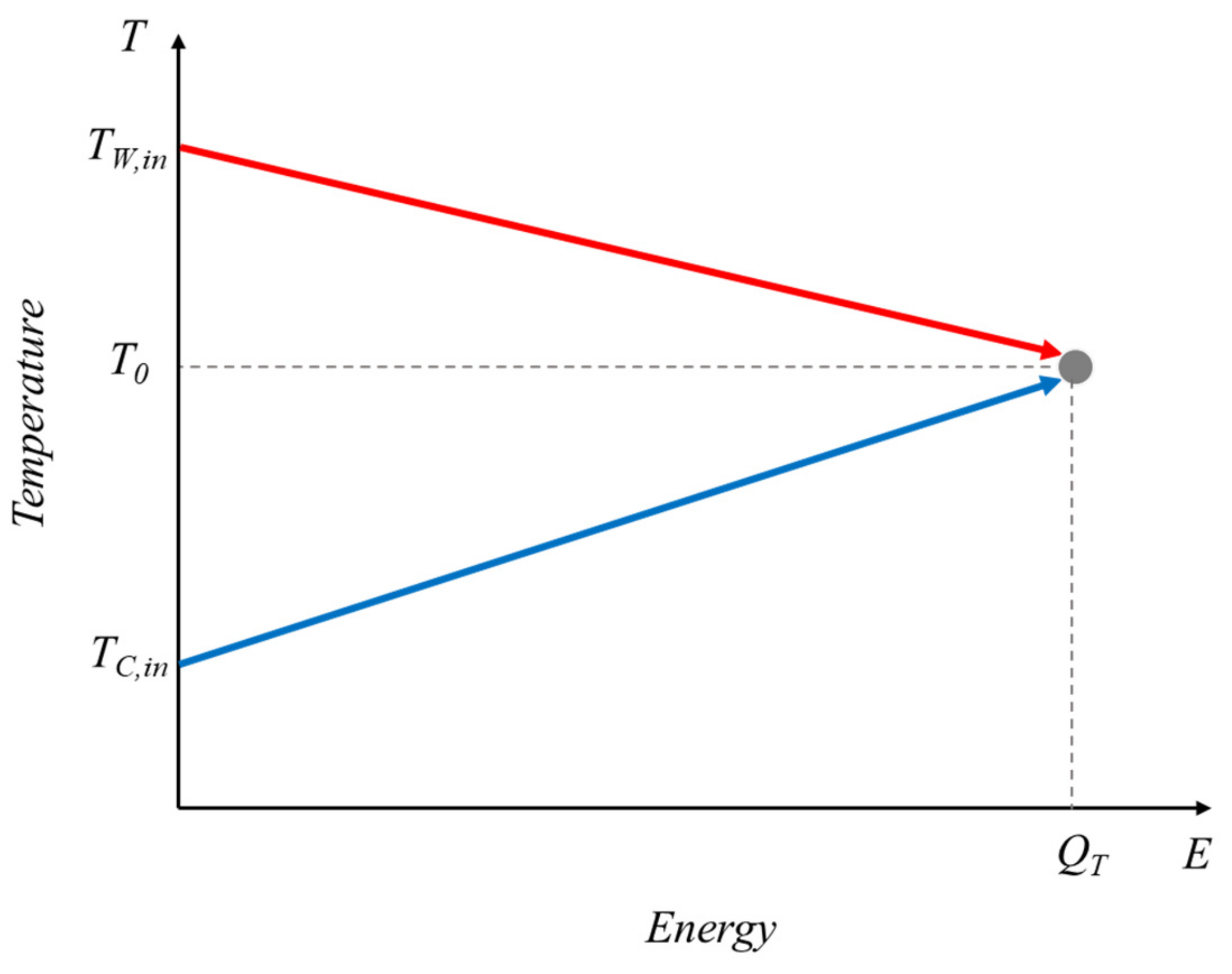
Now, we ascertain the thermal energy stored in the ocean assuming that, after the whole process, the thermal energy will vanish in the adiabatic system. Then, the discharge temperatures will finally become the same (equilibrium condition) by the ideal heat exchange or mixing.
Figure 3 shows the temperature and energy (
T–
E) diagram of seawater without the energy conversion process. It has been shown that the heat transfer rate of surface seawater to equilibrium temperature
T0 (K) can be expressed as a transferable thermal energy
QT (kW) assuming the isobaric change during the heat exchange process [
17]:
Figure 4 shows the
T–
E diagram of the OTEC system using the Carnot heat engine. In the OTEC system, the thermal energy input into the heat engine
Qin is
QW; however, the thermal energy
QW in Equation (6) is a part of
QT. The thermal energy collection efficiency
ηT,in should be considered as defined below:
In the OTEC system, the heat source pumping power is indispensable. The net power of OTEC
Wnet is as follows:
where
WP is the total pumping power of seawater from intake to discharge.
Therefore, the overall thermal efficiency can be expressed as follows:
where the overall thermal efficiency is named the normalized thermal efficiency [
17]. Therefore, the normalized thermal efficiency includes the discharge process in
Figure 2, which is never considered in conventional thermodynamics nor FTTs, to take into account the heat leakage of seawater thermal energy in the energy conversion in OTEC.
In the Carnot cycle, the pumping power is assumed to be negligible and the infinite heat transfer performance in Equations (3) and (12) is expressed as follows [
17]:
In the FTT, the thermal efficiency upper bound in Equation (4) is well known, although the efficiency can exceed Equation (4); however, the concept of thermal efficiency only consider the energy conversion performance of the heat engine. Equation (13) shows that the maximum thermal efficiency in Equation (12) corresponds to the energy conversion efficiency from the heat source thermal energy into the work in the heat engine. This energy conversion efficiency is the normalized thermal efficiency at the maximum power output in the heat engine in Equation (13).
2.2. Exergy Efficiency (Second Law of Thermodynamics)
The irreversibility of OTEC systems occurs due to the finite performance of components such as pumps, heat exchangers, and turbines and the temperature level of heat engines. If the heat source is a constant temperature, such as the conventional thermal energy shown in
Figure 1, the exergy will be the available work of the Carnot cycle. However, in OTEC systems, because the heat source thermal energy is stored as sensible heat in the seawater, the temperature of seawater varies during the heat transfer process. Accordingly, staging heat engines or temperature variation heat engines can increase the available work.
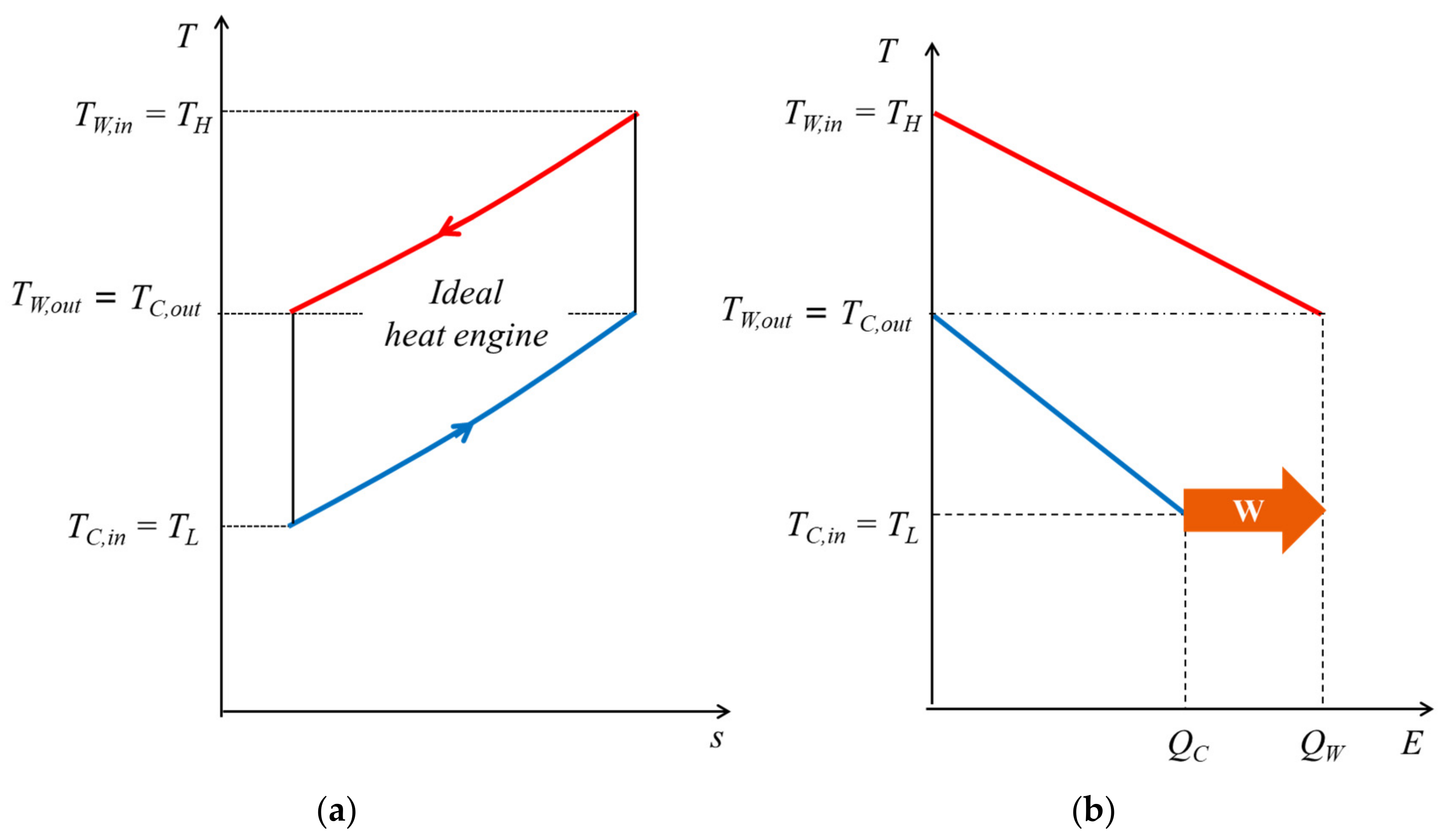
Figure 5 shows conceptual diagrams of an ideal heat engine for OTEC with infinite performance of heat exchangers. In general, an exergy is defined as the available energy in the process that the heat source finally approaches to the ambient temperature, which is generally used the atmospheric temperature between 15 °C and 25 °C depending on the environment. However, in OTEC system, the discharge process finally produces the equilibrium temperature determined by the flow rate and the temperature of the surface seawater and the deep seawater. Therefore, the dead state should be the equilibrium condition of seawater, and the maximum available work will be the exergy in the OTEC.
In
Figure 5, the heat engine temperature varies and completely follows the seawater temperature change during the heat transfer process.
TH and
TL are the highest and lowest temperatures in the heat engine, and they reach
TW,in and
TC,in, respectively.
The entropy production during the isobaric heat exchange process [
17] is:
As shown in
Figure 5, when
Sgen,HE is zero, the discharging seawater temperature is equal because of the equilibrium condition. Then,
TW,out and
TC,out are as follows [
17]:
In addition, the maximum available work of the ideal heat engine is defined as the exergy of OTEC
Ex,OTEC: [
17]:
Therefore, the exergy efficiency of OTEC
ηex,OTEC is expressed as follows:
The increase in the exergy reduces the required flow rate. Specifically, the reduction in the deep seawater flow rate makes the intake pipe diameter small, contributing to reducing the capital expenditure. Then, for the rough exergic comparison method, one simply calculates the rate of power over the deep seawater flow rate Wnet/mC.
3. Effectiveness of Performance Evaluation Method
Table 1 shows the design condition of the variable reference data in OTEC. In
Table 1,
Wgross shows the power from heat engines because the pumping power of seawater is different in each location of the project, and it affects the results of ascertaining the effectiveness of the performance evaluation methods. Note that the assumption of the efficiency of the component is different in each study; however, this evaluation focuses on the trend of the relationship between thermal and exergic efficiencies.
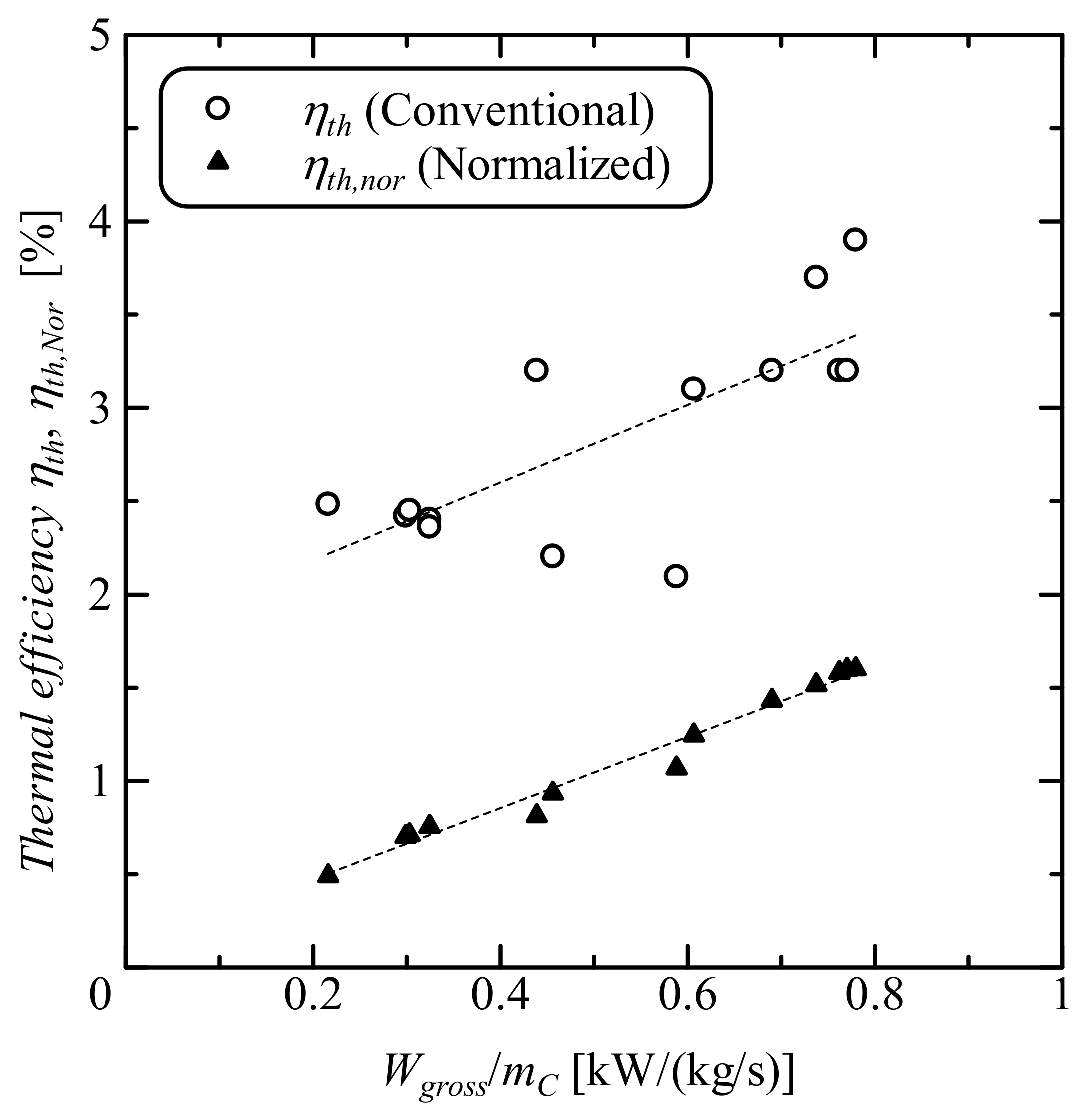
Figure 6 shows the log-scale relationship between
Wgross and the deep seawater flow rate
mC using the data of
Table 1. Moreover,
Figure 7 shows the dependency of conventional and normalized thermal efficiencies
ηth,
ηth,Nor, and
Wgross/
mC.
According to
Figure 6,
Wgross seems to be proportional to
mC because
mC has the similar role as fuels in conventional power plants and an increase in
mC results in increase in
Wgross. Therefore, the increase in
Wgross/
mC will increase the efficiency of heat engines. However, according to
Figure 7,
ηth has no clear correlation to
Wgross/
mC. Additionally,
ηth is almost constant up to
Wgross/
mC at 0.4, and there is considerable variation between
ηth and
Wgross/
mC, whereas the normalized thermal efficiency is almost proportional to
Wgross/
mC. Therefore, although the values of
ηth,Nor are smaller than
ηth, this indicates the energy conversion efficiency. According to
Figure 7, the trend of
ηth clearly shows that the conventional thermal efficiency has the contradiction to indicate the performance of the system as efficient because
Qin is obviously not the resource of energy in the OTEC, but most research only introduces
ηth as the thermal efficiency by following the traditional manner. Moreover, the crucial points in the thermal efficiency are relatively higher
ηth in
Figure 7 such as the points at
Wgross/
mC being 0.22 and 0.44;
ηth,Nor becomes lower compared to other points, which shows us the risk of the performance evaluation or design based on
ηth. Additionally, this is why we need normalization of the resource of energy in the thermal efficiency using
QT to consider the heat leak in the discharge process in
Figure 2. Indeed, the values of
ηth,Nor are small because the resource of thermal energy
QT in Equation (12) includes the discharged thermal energy of heat engines to discharge process in
Figure 2 to be equilibrium state.
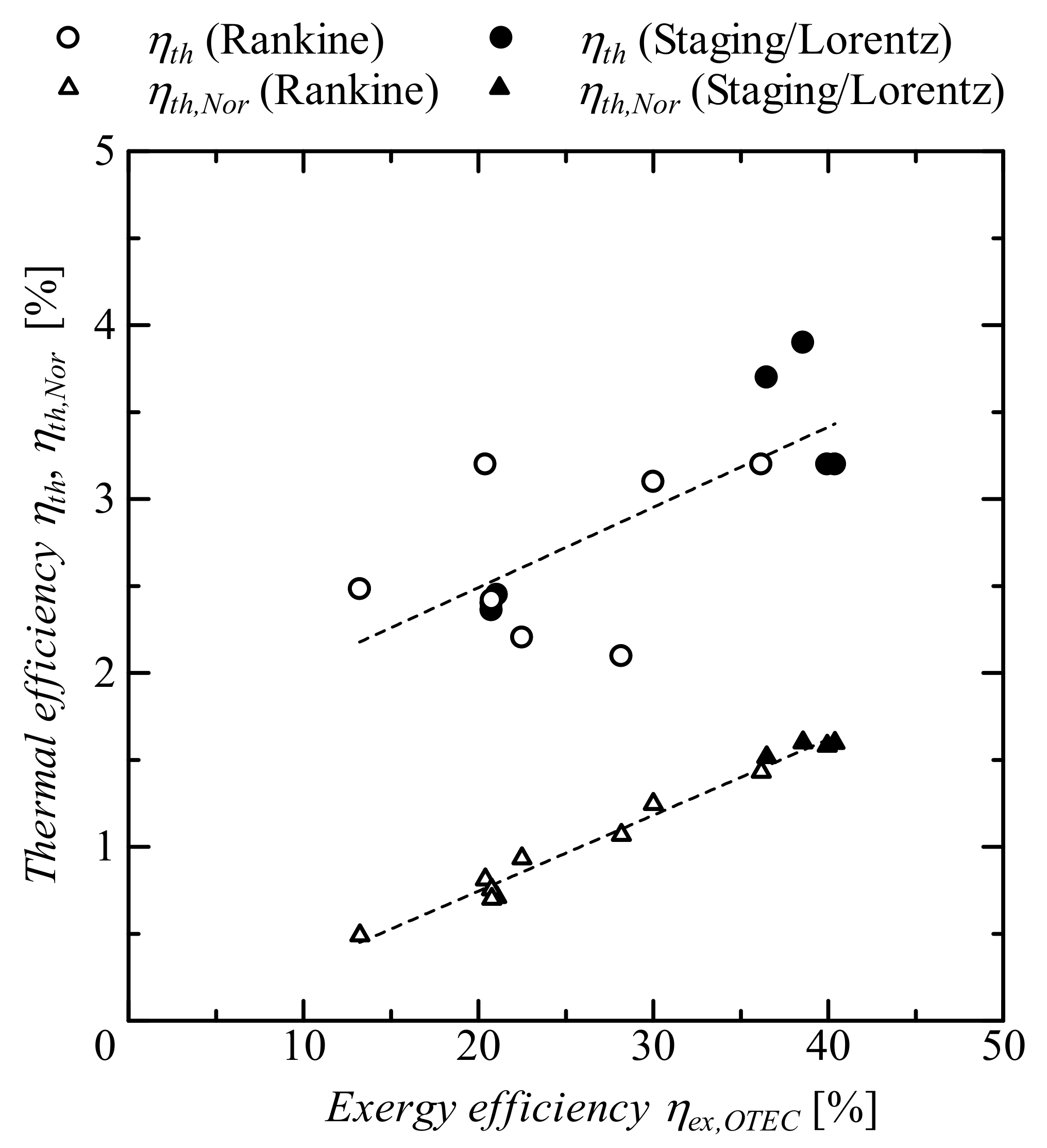
Figure 8 represents the relation between the exergy efficiency
ηex,OTEC defined in Equation (17) and the conventional and normalized thermal efficiencies
ηth and
ηth,Nor. According to
Figure 8, the increase in
ηex,OTEC provides only increase in
ηth,Nor and no clear relation between
ηth and
ηex,OTEC. Additionally,
ηex,OTEC are totally different in the staging of Rankine or Lorentz-like heat engines of
ηth, whereas
ηth,Nor is proportional to
ηex,OTEC except the highest thermal efficiency condition due to the difference of design heat source temperature condition, while the purpose of the utilization of the staging Rankine and Lorentz-like cycle are to increase
ηex,OTEC, and eventually most of their design condition achieves 35–40%. However, some of their
ηex,OTEC are only about 20% and totally less than almost all of the simple Rankine cycle. Therefore, the exergy analysis using Equation (17) is very important to analyze the effectiveness of the design and the potential of improvement of design imbalance the in heat and mass balance.
As shown in
Figure 7 and
Figure 8, for a better understanding of the design heat and mass balance condition and to maximize the available power from the heat source, the utilization of the normalized thermal efficiency and the exergy efficiency defined in Equations (12) and (17) is effective, and is able to evaluate the power generation system in OTEC appropriately. In addition,
Figure 8 shows the trend of higher exergy efficiency and a higher normalized thermal efficiency in the case of the staging of Rankine or Lorentz-like heat engines. However, a few of the staging of Rankine and Lorentz-like heat engines have poor performance, although the potential to improve the performance by optimizing the heat and mass balance is large. According to the exergy efficiency results, the highest value is 40%, so the development of the OTEC system is likely to improve the performance in the future.
4. Conclusions
The concept and design constraints of OTEC power generation differ from those of conventional thermal power plants due to the utilization of a low temperature difference and the design constraint difference. This research theoretically recognized the unique characteristics in the energy conversion system and summarized the appropriate performance evaluation methods for OTEC based on FTTs. In addition, this research summarized the concept of a normalization approach of thermal efficiency and exergy efficiency for OTEC. Theoretically, the principle of normalization is to recognize that, in the thermal efficiency, the heat source thermal energy as the temperature difference between surface and deep seawater not as the input energy to the heat engine, and that, in the exergy efficiency, the energy will vanish at the dead state when the temperature becomes same at equilibrium condition to consider the maximum available work.
The differences between conventional thermal efficiency and the effectiveness of the evaluation methods as well as the risk of design based on increasing conventional thermal efficiency were ascertained using the various reference design data. Additionally, it was confirmed that there is no clear relation between the conventional thermal efficiency and exergy efficiency. However, the exergy efficiency is definitely proportional to the normalized thermal efficiency, whereas the exergy efficiency showed the effectiveness of the staging Rankine, Kalina, and Uehara cycles. The results shows the effectiveness of the normalized thermal efficiency and the exergy efficiency on evaluation of design, operation as well as research and development.
In future work, the reason for exergy destruction should be recognized in the performance evaluation system to determine how to improve the system.


