Article

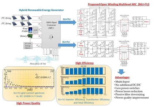
Multi-Level Multi-Input Converter for Hybrid Renewable Energy Generators

1
Dipartimento di Ingegneria, University of Messina, 98166 Messina, Italy
2
Dipartimento di Ingegneria Elettrica Elettronica e Informatica, University of Catania, 95125 Catania, Italy
*
Author to whom correspondence should be addressed.
Energies 2021, 14(6), 1764; https://doi.org/10.3390/en14061764
Submission received: 24 February 2021 / Revised: 17 March 2021 / Accepted: 19 March 2021 / Published: 22 March 2021

Abstract

:
A three-phase multi-level multi-input power converter topology is presented for grid-connected applications. It encompasses a three-phase transformer that is operated on the primary side in an open-end winding configuration. Thus, the primary winding is supplied on one side by a three-phase N-level neutral point clamped inverter and, on the other side, by an auxiliary two-level inverter. A key feature of the proposed approach is that the N-level inverter is able to perform independent management of N − 1 input power sources, thus avoiding the need for additional dc/dc power converters in hybrid multi-source systems. Moreover, it can manage an energy storage system connected to the dc-bus of the two-level inverter. The N-level inverter operates at a low switching frequency and can be equipped with very low on-state voltage drop Insulated-Gate Bipolar Transistor (IGBT) devices, while the auxiliary inverter is instead operated at low voltage according to a conventional high-frequency two-level Pulse Width Modulation (PWM) technique and can be equipped with very low on-state resistance Metal-Oxide-Semiconductor Field-Effect Transistor (MOSFET) devices. Simulations and experimental results confirm the effectiveness of the proposed approach and its good performance in terms of grid current harmonic content and overall efficiency.

Graphical Abstract

1. Introduction

The number of electricity generators powered by renewable energy sources (RESs) is continuously increasing because of concerns about environmental pollution and the limited reserves of fossil energy sources such as oil, coal, and gas [1]. Grid-connected photovoltaic (PV) and wind turbine (WT) generators are the most widely diffused types of RES power plants and their specific cost is continuously decreasing [2,3,4]. However, available solar and wind energy are affected by some factors, such as season cycle, daily cycle, temperature, and weather conditions, which make them intermittent and stochastic. Therefore, a power plant relying only on a single form of RES and without an energy storage capability can hardly cope with the requirements for a reliable electric power generation unit. Hybrid renewable energy systems (HRESs) combining more than one energy source are a viable solution to this problem [5] because they are effective not only in enhancing the reliability of power supply but also in reducing the size of energy storage systems [6,7]. However, in HRESs, a specific dc–dc power converter is normally used to manage each input power source, leading to a quite complex and expensive structure [8,9].
The multiple input power converter (MIPC) concept is a possible alternative to HRESs having to cope with sources with different power capacity and/or voltage levels, providing a well-regulated dc output voltage. Both isolated and non-isolated dc/dc multi-input converters find application in hybrid vehicles [10], the aerospace industry, and RES power plants. A non-isolated double input dc/dc converter is proposed in [11] combining buck and buck-boost single-input topologies, while an n-input buck-boost topology is presented in [12], which however could not supply the load simultaneously from different sources. A bidirectional multi-input dc/dc converter was also developed in [13], which is burdened by high conduction losses. The efficiency of an MIPC can be increased by exploitation of zero voltage switching approaches, as in [14,15]. Some MIPC topologies have been purposely developed for application in HRESs [16]. Among them, three-port dc/dc converters are of major interest. They feature an input port, an output one, and a storage port, enabling a bidirectional power flow towards/from an energy storage system (ESS). Some non-isolated three-port converters are discussed in [17,18,19,20,21].
A different approach is proposed in this paper, where a particular kind of multiple-input multi-level converter (MMC) is exploited to connect photovoltaic and wind generators to an energy storage system and a three-phase ac grid. It is based on an open-end winding configuration, the asymmetrical hybrid multi-level inverter (AHMLI), whose applications on both motor drives and grid-connected generators are discussed in [22,23] and which has also been successfully exploited to reduce the overvoltage caused by long cables in PWM motor drives [24] as well as to realize a high-speed Gen-set [25,26]. In the present HRES application, the AHMLI topology encompasses an open-end winding three-phase transformer (OWT) whose primary winding operates in an open-end configuration. The primary winding is, in fact, supplied on one side by a three-phase neutral point clamped (NPC) multi-level inverter (MLI) and, on the other side, by a conventional two-level inverter (TLI). The MLI operates at a low switching frequency (<1 kHz), thus featuring very low switching power losses. It is tasked to control the active power supplied to the grid, while also managing N − 1 unidirectional input power flows, being N the number of the output voltage levels. Thus, N − 1 energy sources (ESs) such as photovoltaic (PV) strings or wind turbines (WTs) can be managed without the introduction of additional dc/dc power converters. Moreover, it can also accomplish a multi-channel maximum power point tracking (MPPT) function at the string level on PV arrays. Compared with the MLI, the TLI operates at a high switching frequency, but at a lower dc bus voltage. It is tasked to control the grid current and to compensate for low-order current harmonics and unbalanced components. Moreover, its dc-bus can act as the storage port of a three-port dc–dc converter, enabling the connection of an energy storage system (ESS) to the HRES. In other words, energy sources connected to the MLI are managed by the TLI, avoiding the introduction of dc/dc power converters.
The paper is organized as follows. Section 2 presents the proposed approach and its application to 5LI + TLI and 3LI + TLI topologies. In Section 3, the operations of these topologies are discussed. Simulation and experimental results are presented in Section 4 and Section 5, respectively. Finally, Section 7 and Section 8 concern the discussion and conclusion.

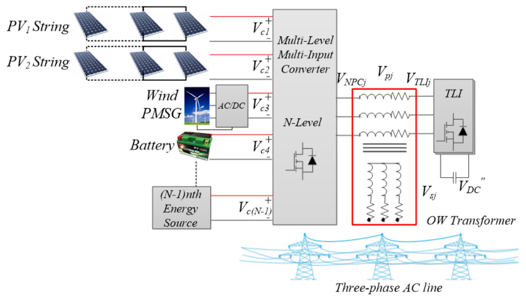
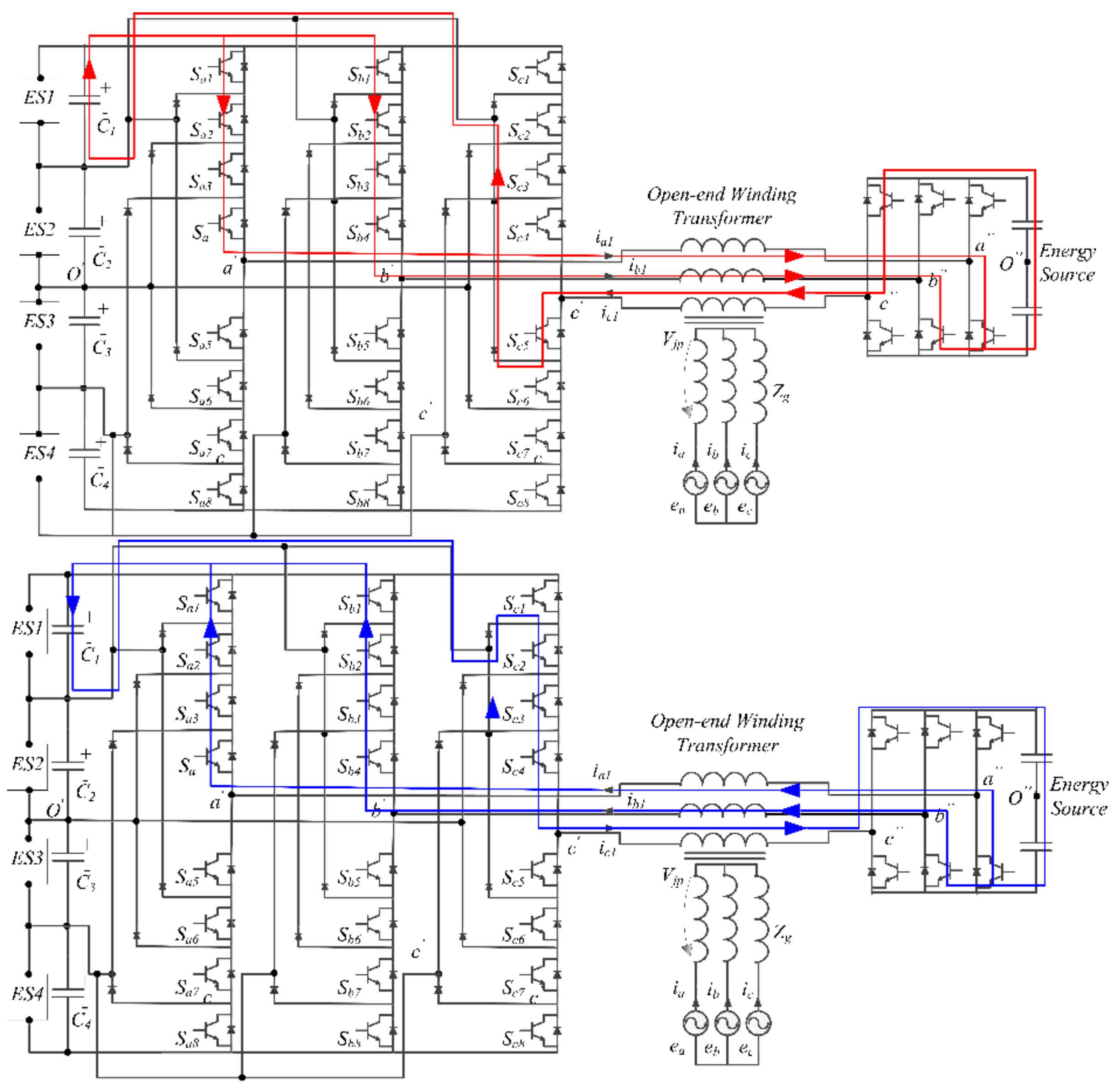
2. The Proposed MMC Topology

The proposed MMC for HRESs, tailored around the AHMLI topology, is shown in Figure 1. The primary winding of the three-phase transformer is connected to an N-level NPC inverter on one side and to an auxiliary TLI on the other side. The secondary winding is instead connected to a three-phase ac grid. The NPC inverter, which acts as an N-level multi-input converter, encompasses N − 1 DC-bus capacitors Cj, each one connected to a dc power source of voltage Vck (k = 1, 2, 3, N − 1). According to the AHMLI topology and assuming that the two inverters are supplied by two independent power sources, VDC and VDC, a phase voltage Vpj (j = 1,2,3,) of the primary winding of the OWT is given by:
V p j = V N P C j V T L I j   V O O = 2 l 2 4   V D C 2 l 1 V D C / 2 V O O l = 0 , 1 , 2 l = 0 , 1
where VNPCj is the NPC output j-phase voltage referred to the mid-point O (Equation (2)), VTLIj is the TLI output j-phase voltage referred to the mid-point O (Equation (3)), VDC is the dc-bus voltage of the TLI, VDC is the total dc-bus voltage of the NPC, and VOO is the voltage between the mid points O and O of the dc-buses of the two inverters (Equation (4)).
V N P C j = 2 l 2 4   V D C l = 0 , 1 , 2
V T L I j = 2 l 1 2   V D C l = 0 , 1
V O O = 1 3 j = 1 3 ( V M L I j V T L I j )
As VNPCj may take N levels, while VTLIj may take two, the transformer primary phase voltage Vpj may take 2N levels, whose amplitude is a function of VDC and VDC. Table 1 shows that in terms of phase voltage levels, the proposed configuration is equivalent to a conventional multi-level inverter with a larger number of power devices. From another point of view, a lower phase voltage THD (Total Harmonic Distortion) is obtained with the same number of switches.
As an example of an HRES application of the AHMLI topology, a six-level MMC is shown in Figure 2. PV strings, or groups of strings, are directly connected to the NPC’s dc-bus capacitors while the permanent magnet synchronous generators of the wind turbines are connected through a three-phase controlled rectifier or a diode rectifier and an output dc-link capacitor. All dc sources must have about the same rated output voltage in order to prevent largely unbalanced dc-bus voltages. However, the TLI is able to compensate a NPC DC-bus capacitor voltage variation ΔVc provided that it is lower than VDC, thus achieving a sinusoidal grid current. The dc-buses of the NPC and auxiliary inverters are isolated between them in order to prevent the circulation of zero-sequence currents [22]. Moreover, the TLI dc-bus is supplied through a floating capacitor; thus, an additional power source is not required. Another example is shown in Figure 3, where a five-level NPC inverter is used. In this case, an ESS is connected to the TLI dc-bus, and a bidirectional power flow can be managed towards/from the ESS. In both examples, the NPC provides the active power flow to the grid, while the TLI works as an active power filter, while also regulating the output current and the NPC dc-bus capacitor voltages Vck.

3. Proposed MMC Topology Operation

In order to manage multiple input sources while controlling the main power flow towards the grid, a suitable control system has been developed that is divided into two main parts: an MLI control subsystem and a TLI control subsystem.

3.1. MLI Control Subsystem

MLI switching power losses are kept low by taking advantage of low-frequency space vector modulation (SVM) or step modulation (ST). However, these modulation techniques must be suitably modified to allow for a direct periodical connection between the N − 1 energy sources connected to the MLI dc-bus and the TLI. This is necessary to enable independent voltage control on each of the N − 1 MLI dc-bus capacitors. According to (1), the space diagram of the transformer primary phase voltage Vjp is obtained by combining the voltage space vector diagrams of the two inverters. The simplest MMC configuration that can be obtained according to the proposed approach encompasses a three-level inverter (3LI + TLI), which provides six voltage levels if VDC = VDC/(N − 1). Such an MMC may take 33 = 27 switching states; however, only 19 different voltage vectors can be generated, because some of the switching states are redundant. The MMC voltage space vector diagram can be obtained by adding the voltage space vector diagram of the TLI at the top of each voltage vector of the 3LI, as shown in Figure 4 [27]. Each input dc source can be independently managed by exploiting its periodical connection to the transformer’s primary winding, which occurs when the 3LI generates one of the twelve possible low-voltage vectors (LVVs), namely PPO, OON, POO, ONN, ONO, POP, NNO, OOP, NOO, OPP, NON, and OPO, according to Figure 4 and Table 2. As an example, Figure 5 shows that when the voltage vector PPO is generated, the capacitor C1, which represents the output capacitor of the energy source ES1, is directly connected to the TLI. Hence, when the voltage vector PPO is generated, VC1, that is, the voltage across C1, can be regulated by controlling the power stream between the 3LI and the TLI. This is accomplished through a closed loop voltage controller managing the power exchange between ES1 and the TLI dc-bus capacitors through a specific set of components Vkj of the TLI reference voltage, as shown in Figure 5c. In practice, the voltage regulator, by processing the difference between the C1 reference voltage Vc1 * and the actual value Vc1, generates a coefficient I, which is multiplied by the actual values of the transformer’s primary currents to obtain Vkj. Therefore, if I is positive, an additional power transfer is instated directed towards C1, thus increasing Vc1. If I is negative, the additional power flow is directed from C1 to the TLI dc-bus capacitors, thus discharging C1 and reducing Vc1. Hence, it is possible to charge or discharge C1 when the MLI generates the vector PPO. The same applies for the other dc bus capacitors when the MLI is generating the specific LVV.
In general, for a N-level NPC converter, N − 1 space vectors can be exploited for controlling N − 1 input dc sources. For instance, Figure 6 shows the space phasor diagram of a 10-level MMC composed of a five-level NPC and a TLI (5LI + TLI) as that shown in Figure 3, where VDC″/VDC is set to 0.25. The energy sources that can be managed in this case are four, namely ES1, ES2, ES3, and ES4, each one connected to the MLI dc-bus through an output capacitor Cj (j = 1…4). The voltage VCj across the output capacitor Cj can be regulated by acting on the six LVVs shown in Figure 6, being P1, P2, O, N1, and N2 the possible states of the j-leg, as shown in Table 3. When the vector R2 (P2P2P1) is generated, the capacitor C1 is directly connected to the TLI through the primary windings of the transformer, as shown in Figure 7, making possible the regulation of the voltage Vc1 by controlling the power stream between the two converters.
For low modulation indexes, it is possible to regulate the voltage of the N − 1 dc-bus capacitors without modification of the conventional multilevel SVM or SM strategies, because the top of the reference voltage vector Vm * always lies inside the hexagon encompassing R1, R2, R3, R4, R5, and R6. According to the basic multi-level SVM strategy, the voltage–time Equation (5) referred to a stationary q,d reference frame gives the switching times ta, tb, and tc from the voltage reference Vm * and the switching period Tm. As shown in Figure 8a, for low modulation indexes, Va coincides with the null state V0, while Vb and Vc are those LVVs whose tops coincide with the vertices of the triangle in which the top of the reference voltage vector lies. However, as shown in Figure 8b, for medium and high modulation indexes, no LVVs are selected according to the conventional SVM strategy; thus, they must be purposely introduced in the inverter switching path. This can be obtained by substituting one of the vectors Va, Vb, or Vc of Equation (5) with a switching sequence including the LVV that must be activated, and other two voltage vectors V1 and V2. If, as shown in Figure 8c, the LVV R 1must be activated, the switching times tR, t1, and t2 are given by Equation (6), being Ta obtained by solving Equation (5). A similar procedure can be adopted to modify the switching patterns generated according to the standard multi-level SM.
T m V m α =   t a V a α + t b V b α + t c   V c α T m V m β =   t a V a β + t b V b β + t c   V c β   T m =   t a + t b + t c
T a V a α =   t 1 V 1 α + t 2 V 2 α + t R   V R 1 α T a V a β =   t 1 V 1 β + t 2 V 2 β + t R   V R 1 β   T a =   t 1 + t 2 + t R

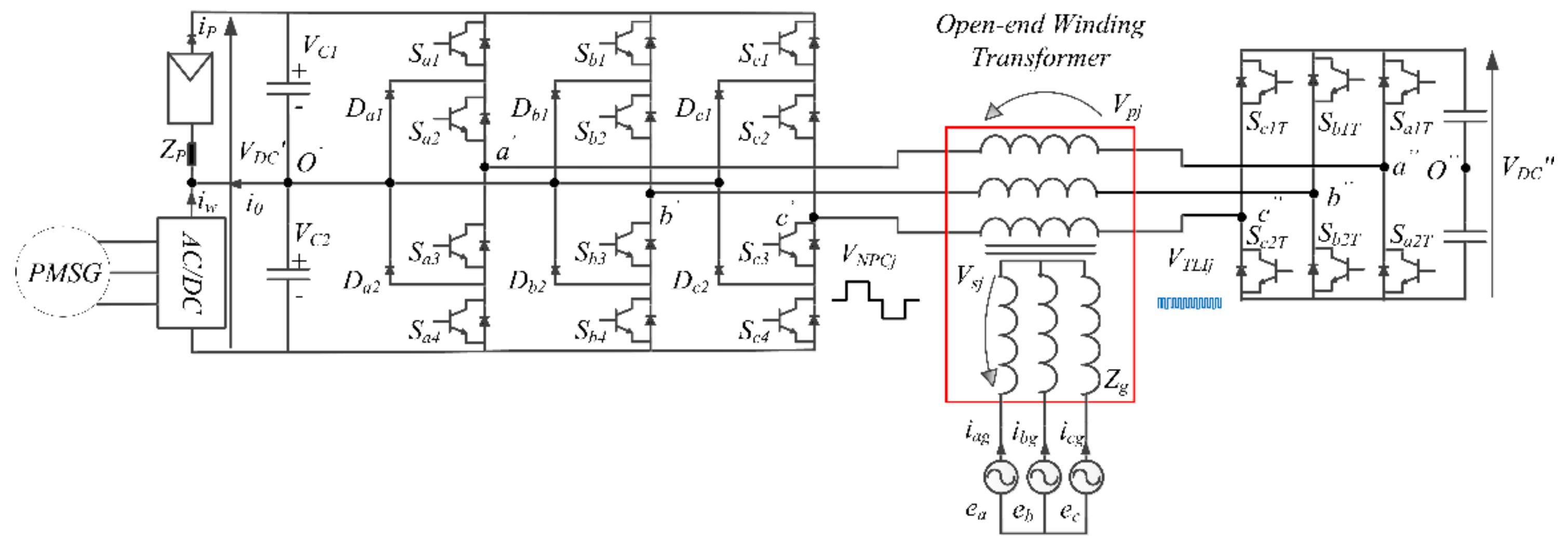
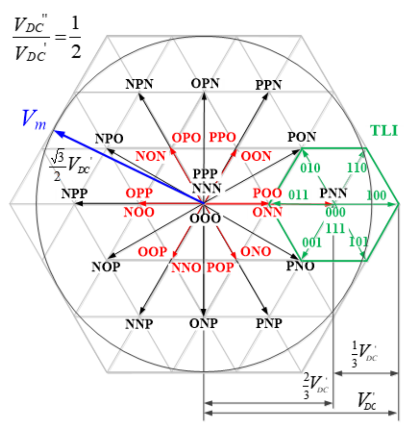
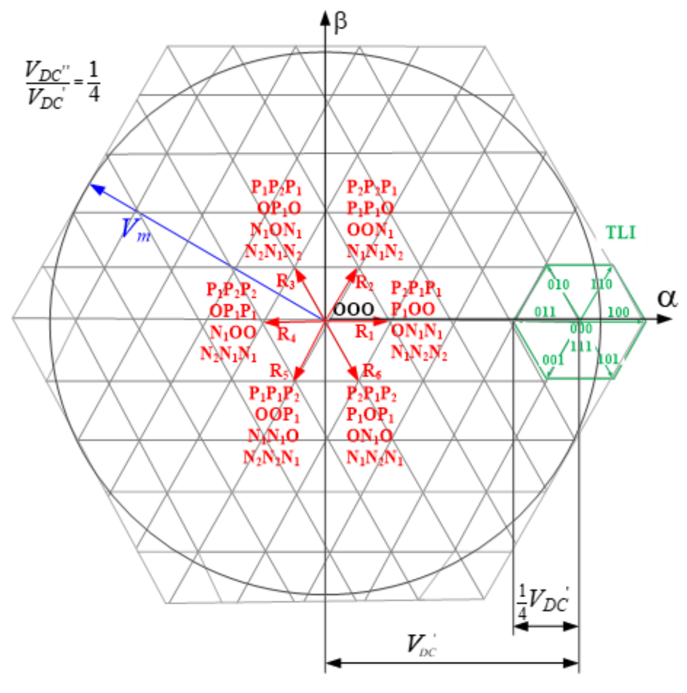
3.2. TLI Operation and 3LI + TLI Control Algorithm

Transformer primary voltage harmonics generated by low-frequency modulation of the main inverter are then cancelled by the TLI. In fact, the TLI working at a high switching frequency plays the role of an active power filter while also managing the power flows originating from the N − 1 energy sources connected to the MLI dc-bus and compensating for possible imbalances caused by different dc-bus capacitor voltages. This makes it possible to avoid the introduction of additional dc/dc converters, which otherwise would be necessary to connect each energy source to the system. The MMC control system encompasses a synchronous qd current controller regulating the transformer’s primary current and the N − 1 voltage controllers to manage the energy sources connected to the MLI dc-bus [28]. A schematic of the control system developed for the proposed MMC is shown in Figure 9 for a 3LI + TLI configuration. It consists of three main blocks, namely TLI dc-bus current (battery) control, NPC dc-bus voltage (energy sources) control, and regulation of active and reactive power at the primary side of the transformer. Moreover, a N − 1 channels maximum power point tracking function can be provided in order to cope with PV arrays connected as energy sources. In this case, according to Figure 5, the MPPT sets the reference voltages Vc1 and Vc2, whose sum VDC *′ constitutes the reference for the q-axis 3LI current regulator. The reactive power is instead controlled by acting on the d-axis current. An independent control on Vc1 and Vc2 is obtained by two voltage controllers, whose outputs are processed in order to obtain the components Vkja of the TLI reference voltages as shown in Figure 5c. Whenever one LVV is active, k is set to 1 and the reference coefficient I is computed to charge or discharge the considered capacitor. At the same time, the correct MLI voltage vector path is selected according to Equations (5) and (6) in order to connect the specific energy source to the TLI, thus establishing a power stream from the energy source to the TLI d-bus. Further components of the TLI reference voltage Vhj and Vbattj are computed dealing, respectively, with the compensation of harmonics generated by the low-frequency operation of the MLI (Equation (7)) and control of the battery current iDC. Hence, the j-phase TLI reference voltage is given by Equation (8) while Vhj is written in (7).
V h j =   V N P C j V 1 N P C j
V T L I j =   V h j + V B a t t j + V k j
being V1NPCj the fundamental component of the NPC output phase voltage VNPCj. The TLI current control is also able to compensate for imbalanced voltages on the 3LI dc-bus by adapting the duty cycle of the TLI at each half-cycle. This capability depends on the value of VDC, which is the maximum capacitor voltage deviation value that can be compensated for. Hence, the TLI ensures a sinusoidal grid-current during Vc = Vcn ± VDC for all NPC dc-bus capacitors.

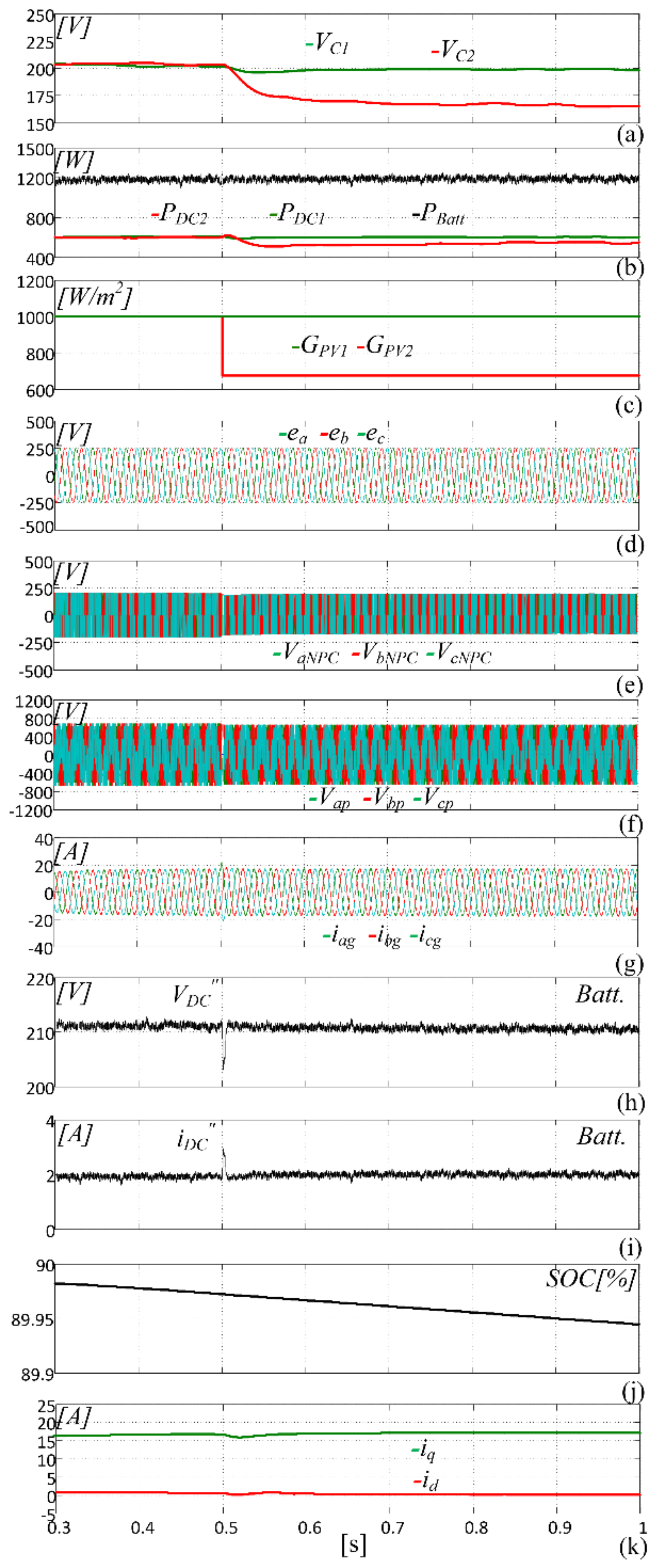
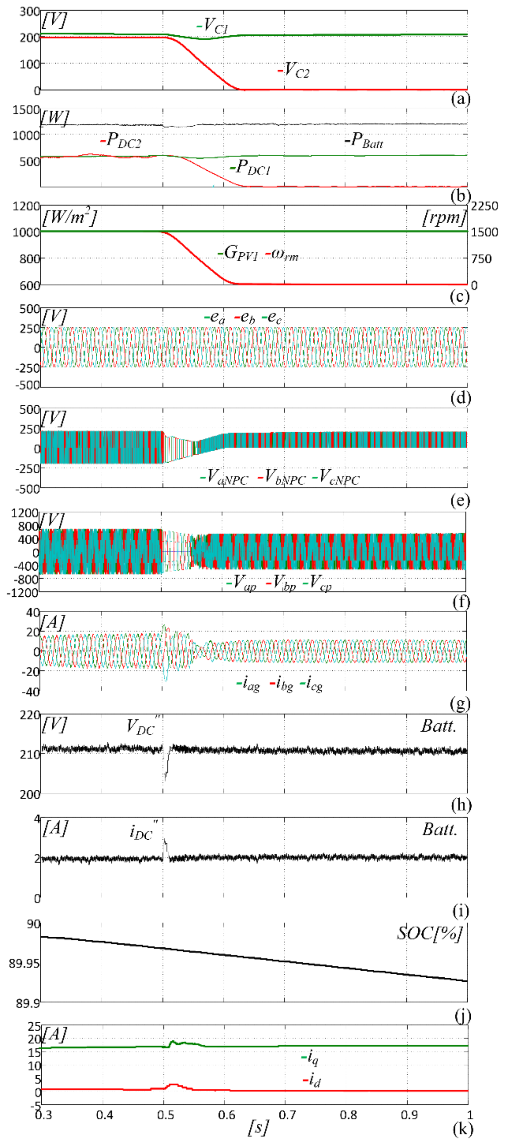
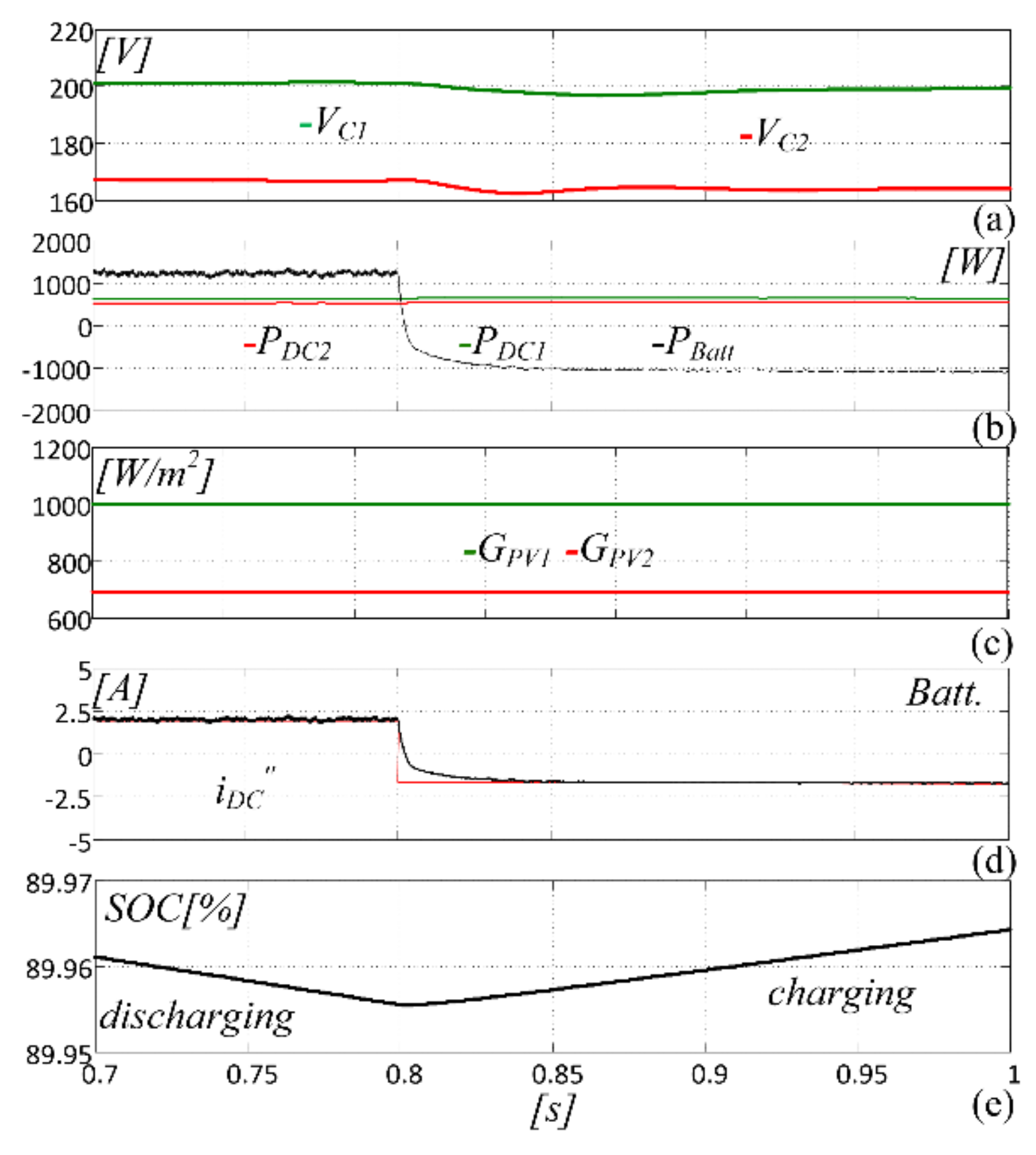
4. Simulation Results

The effectiveness of the proposed topology was first evaluated through a simulation, taking into account a scaled model of a hybrid renewable energy generator tailored around an open-end winding 5 kVA-230/400 V three-phase transformer, a three-level NPC inverter exploiting a 1 kHz SVM strategy with a 400 V dc-bus voltage, a TLI PWM operating at 10 kHz, and a three-phase grid. The parameters of the system components are listed in Table 4, Table 5, Table 6, Table 7, Table 8, Table 9, Table 10 and Table 11. These include the main data of the IGBT and diodes on the NPC MLI and those of the power MOSFET devices present on the TLI.
Two cases are taken into consideration: a fully PV system with an ESS; and a hybrid PV–wind one with an ESS. The system model was developed using the MATLAB/Simulink environment and setting a 1 μs sample time. Output power characteristics of the PV modules are shown in Figure 10. Each PV string consists of five modules in order to achieve a peak voltage of 200 V on the NPC dc-bus capacitors C1 and C2. Operation of the first configuration is shown in Figure 11, dealing with NPC dc-bus voltages Vc1 and Vc2, the output power of ES1, ES2, and the battery, the irradiances of PV strings GPV1 and GPV2, the transformer’s primary and secondary voltages, the NPC output voltages VNPCj, the grid currents, the TLD bus voltage VDC and current iDC, the battery’s state of charge (SOC), and the qd-axes current components. At t = 0.5 s, the solar insolation on the ES2 PV string falls down from 1000 W/m2 to 700 W/m2. Then, the ES2 output power decreases from 600 W to 560 W. According to Figure 10, the voltage Vc2 is then reduced to track the maximum power point by acting on the TLI according to the voltage control scheme of Figure 5c. Once Vc2 has reached the new optimal value, an imbalanced voltage condition (Vc1 = 200 V, Vc2 = 165 V) occurs. However, the three-phase grid currents are kept sinusoidal by the TLI current control system by drawing power from the ESS, as the SOC diagram confirms. In this case, in fact, the TLI dc-bus voltage VDC = 210 V is sufficient to compensate for the ΔVc2 = (200 − 165) V = 35 V voltage deviation. Figure 12 deals instead with operation of the second configuration, when the rotor speed of the wind turbine ωrm drops from 1500 to 0 rpm. Additionally, in this case, the TLI dc-bus voltage VDC = 210 V is sufficient to compensate for the ΔVc2 = (200 − 200) V = 0 V voltage deviation. The proposed system is able to manage a bidirectional power stream towards/from the energy storage system as shown in Figure 13. The irradiances considered for PV1 and PV2 are not the same, being respectively 1000 W/m2 and 700 W/m2, while the battery current varies from 2.5 A to −2.5 A. The battery SOC trend demonstrates the bidirectional power capability of the proposed configuration.

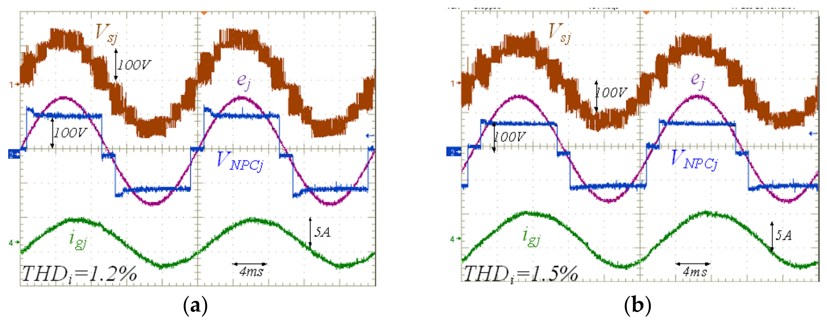
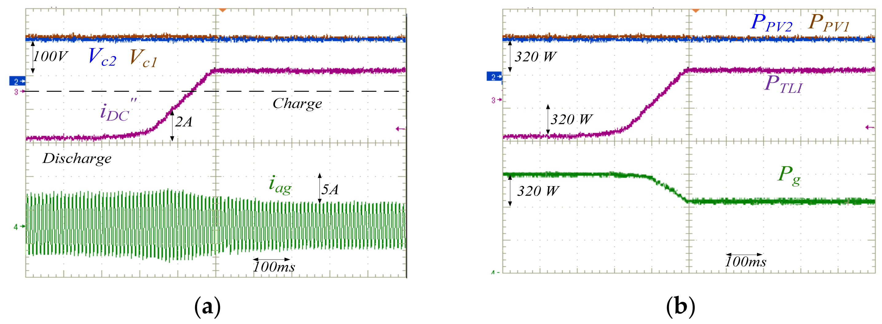
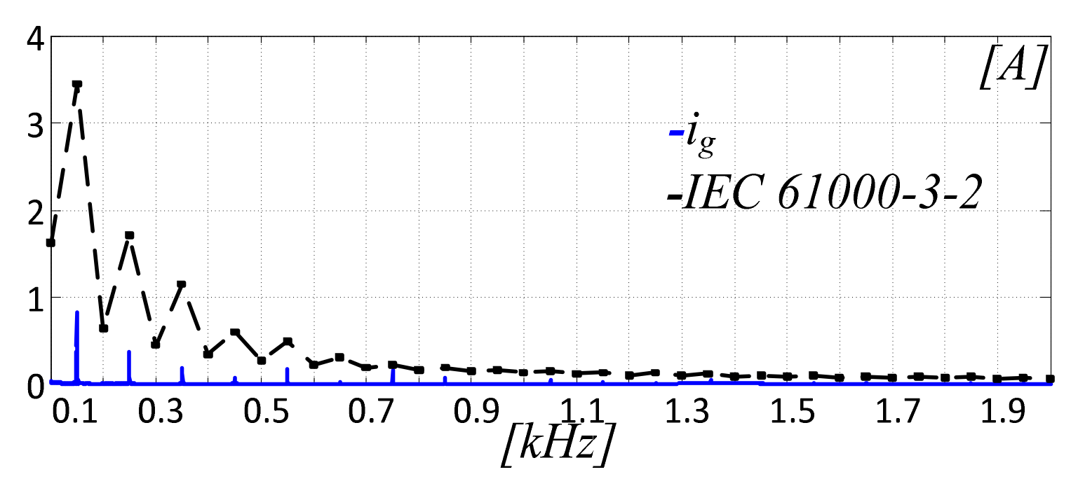
5. Experimental Assessment

Experimental tests were accomplished on a six-level MMC encompassing an open-end winding 5 kVA–230 V/400 V three-phase transformer, a 3LI-NPC inverter with a 200 V dc-bus voltage exploiting an SM strategy, and a two-level inverter PWM operating at 10 kHz. A 100 V, 40 Ah Lithium-ion battery was connected to the dc-bus of the TLI. All system parameters are listed in Table 4, Table 5, Table 6, Table 7, Table 8, Table 9, Table 10, and Table 11. The control system was realized around a DSpace/1103 board running at 10 kHz. The primary winding of the transformer was connected, on one side, to the NPC MLI and, on the other side, to the TLI. Programmable PV module emulators played the role of two PV strings connected to the NPC dc-bus. Steady-state operation under balanced and imbalanced conditions is shown in Figure 14a,b, dealing with the 3LI + TLI output voltage, grid voltage, grid current, and 3LI output step voltage. In Figure 14a, a balanced condition is considered with Vc1 = 100 V, Vc2 =100 V. Hence, the TLI acts only as an active power filter in order to compensate for the low-order harmonic generated by the NPC low switching frequency modulation. Figure 14b instead deals with the imbalanced condition with Vc1 = 100 V, Vc2 =70 V, and VDC = 100 V. Although the NPC dc-bus voltages are imbalanced, the grid current is sinusoidal with a THD as low as 1.5%. In this case, the TLI not only works as an active filter but also as a voltage imbalance compensator. A reduction in the dc voltage generated by PV1 string is shown in Figure 15a, where Vc1 is changed from 100 V to 70 V. Such an imbalance causes a variation in the peak voltage in the positive half-cycle of VjNPC, but the current is kept sinusoidal by the TLI. Figure 15b deals with power generated by the two PV strings PPV1 and PPV2 provided by the battery PTLI and the output one Pg. The reduction in Vc2 causes a reduction in PPV2 from 320 W to 180 W according to the P–V profile of Figure 10. The same power variation is present in the grid power Pg because the active power produced by the TLI’s battery is kept constant. Figure 16 shows a detailed view of the waveforms of VaNPC and iag in the test of Figure 15. The TLI compensates for the unbalanced voltages and almost perfectly shapes the grid current.
A further test was performed dealing with battery current control, as shown in Figure 17, dealing with battery current, voltages Vc1 and Vc2, and grid current. The voltages are kept balanced at Vc1 = 100 V and Vc2 = 100 V, while the battery current is changed from −3 A to 2 A. Hence, the battery is first discharged and then charged. A negative battery current means that the battery feeds power Pbatt to the grid according to Figure 17. Vice-versa, a positive battery current means that the battery is charged from the grid. The harmonic spectrum of the grid current at a rated load is shown in Figure 18, fully complying with the IEC 61000-3-2 standard on power quality.

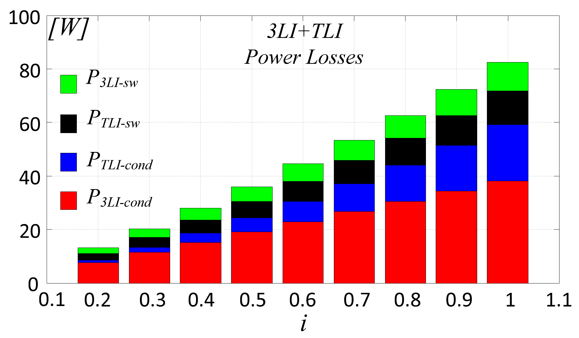
6. Power Losses Analysis

A power losses analysis was accomplished by considering the efficiency η3LI + TLI of the 3LI + TLI converter and that of the transformer ηTR. Hence, the total efficiency is obtained as Equation (9). The efficiency of the converter was estimated by computation of the power devices conduction Pc and the switching Psw losses. According to [29], the 3LI is equipped with a high-voltage and low-frequency IGBT, while a low-voltage, high switching frequency MOSFET is used in the TLI. The main data on these power devices are listed in Table 9, Table 10 and Table 11. Conduction losses of the IGBT and MOSFET were computed according to Equations (10) and (11), respectively, while switching losses were evaluated by Equation (12) for both power switches. Furthermore, the diodes’ reverse recovery power losses are also considered in Equation (13) and were included in the total power losses calculation.
η T o t = η 3 L I + T L I η T R
P c _ M L I = δ V c e ( o n ) i R M S
P c _ T L I = R D S ( o n ) i R M S 2
P s w = 0.5 V c e i R M S f s w ( t r i s e + t f a l l )
P D = V D R f s w ( t r d i R M S + Q r )
η T R = A n cos ( φ ) A n cos ( φ ) + i P f e n + P c u n / i
where δ is the duty cycle, tr and tf are the rise and fall times of the power switches, iRMS is the Root Mean Square (rms) value of the switch current, Vce is the collector-to-emitter voltage, Vce(on) is the collector-to-emitter saturation voltage, RDS(on) is the static drain-to-source on resistance, fsw is the switching frequency, VDR is the diode’s reverse voltage, trd is the diode’s reverse recovery time, and Qr is the reverse recovery charge. The efficiency of the three-phase transformer was computed as a function of iron losses Pfen, rated copper losses Pcun, power factor cos(φ), rated power An, and load coefficient I = ig/ign, being ign the rated current of the transformer, Equation (14). Figure 19 shows the conduction and switching losses of the two inverters as a function of the load coefficient i. Specifically, P3LI_cond and PTLI_cond are the conduction losses of 3LI and TLI, respectively, while P3LI_sw and PTLI_sw are the switching losses, which increase with the load current from 2.6% at i = 0.1 to 8% at i = 1. The switching power losses of the 3LI are quite low due to the low switching frequency. The total efficiency of the two inverters η3LI + TLI and that of the transformer ηTR are shown in Figure 20 as function of the load ratio. The peak efficiency of the converter is 98.9% at i = 1, while the minimum is 95.2% at i = 0.2. The efficiency of the transformer, ηTR, reaches its peak value of 96.5% for i = 3/4. Finally, the total efficiency was obtained according to Equation (9) and is shown in Figure 20c. It reaches the maximum value of 95% at i = 0.7.

7. Discussion

Simulation and experimental results confirm that independent management of N − 1 power sources and an ESS can be accomplished by using an AHMLI structure composed of a N-level inverter, an open primary winding transformer, and a two-level inverter. This makes unnecessary the introduction of additional dc–dc converters to connect the input ES and the ESS to the grid inverter. Such a structure is also able to compensate for a possible imbalance among the output voltages of energy sources, provided that it does not exceed the dc-bus voltage of the auxiliary TLI. Under this limit, the proposed configuration is also able to cope with a full shut-down of one of the input ESs. Moreover, an independent N − 1-channel MPPT can be provided to manage multi-string PV arrays. As proved by experimental tests, the proposed configuration produces an almost perfectly sinusoidal grid current, despite the fact that the main inverter is operated at a low switching frequency in order to improve the efficiency. In fact, the current shaping is accomplished by the auxiliary TLI, which operates at a high switching frequency, but at a remarkably lower dc-bus voltage. This allows us to equip the TLI with fast and powerful MOSFET devices producing low switching and conduction power losses. The efficiency performance of the proposed structure is confirmed by a power losses analysis, which gives global efficiency levels similar to those obtainable with conventional conversion systems for HRESs, but with a more simple and less expensive structure.

8. Conclusions

The goal of this work was to prove that a multi-input conversion system can be constructed from an AHMLI topology exploiting an open-end primary winding transformer. The coherence of such a concept was confirmed first theoretically and then by simulation and experimental tests. Applied to hybrid renewable energy systems exploiting multiple energy sources and an energy storage system, the proposed approach allows us to largely reduce the complexity and cost of the power conversion systems, avoiding the introduction of additional dc–dc converters to interface each energy source with the grid-connected inverter. Further developments of the proposed concept will deal with applications in other sectors, such as electric vehicles and the aerospace industry.

Author Contributions

A.T. and S.F. conceived the original idea. A.T., S.F. and L.D.T. developed the theory and performed the computations. S.D.C., G.S. and M.C. verified the analytical methods. All authors discussed the results and contributed to the final manuscript. All authors have read and agreed to the published version of the manuscript.

Funding

This research received no external funding.

Institutional Review Board Statement

Not applicable.

Informed Consent Statement

Informed consent was obtained from all subjects involved in the study.

Data Availability Statement

Not applicable.

Conflicts of Interest

The authors declare no conflict of interest.

References

  1. Sefa, I.; Altin, N. Grid interactive photovoltaic inverters—A review. J. Fac. Eng. Archit. Gazi. Univ. 2009, 24, 409–424. [Google Scholar]
  2. Bhol, S.; Charansahu, N. Performance Analysis and Cost Calculation of Standalone PV-DG Generation System without Storag. In Proceedings of the CISPSSE, Keonjhar, Odisha, India, 29–31 July 2020; pp. 1–5. [Google Scholar]
  3. Moniruzzaman, M.; Hasan, S. Cost analysis of PV/Wind/diesel/grid connected hybrid systems. In Proceedings of the ICIEV, Dhaka, Bangladesh, 18–19 May 2012; pp. 727–730. [Google Scholar]
  4. Tyagi, A.; Dubey, M.; Gawre, S. Advance Monitoring of Electrical and Environmental Parameters of PV System: A Revie. In Proceedings of the SEEMS, Greater Noida, India, 26–27 October 2018; pp. 1–5. [Google Scholar]
  5. Nehrir, M.H.; Wang, C.; Strunz, K.; Aki, H.; Ramakumar, R.; Bing, J.; Miao, Z.; Salameh, Z. A Review of Hybrid Renewable/Alternative Energy Systems for Electric Power Generation: Configurations, Control, and Application. IEEE Trans. Sustain. Energy 2011, 2, 392–403. [Google Scholar] [CrossRef]
  6. Badin, R.; Huang, Y.; Peng, F.Z.; Kim, H.G. Grid interconnected Z-source PV system. In Proceedings of the IEEE PESC’07, Orlando, FL, USA, 17–21 June 2007; pp. 2328–2333. [Google Scholar]
  7. Iannone, F.; Leva, S.; Zaninelli, D. Hybrid photovoltaic and hybrid photovoltaic-fuel cell system: Economic and environmental analysis. In Proceedings of the IEEE Power Engineering Society General Meeting, San Francisco, CA, USA, 16 June 2005; pp. 1503–1509. [Google Scholar]
  8. Chakraborty, S.; Simões, M.G.; Kramer, W.E. Power Electronics for Renewable and Distributed Energy Systems; Springer: Berlin, Germany, 2015; pp. 1–620. [Google Scholar]
  9. Núñez, J.V. Multilevel Topologies: Can New Inverters Improve Solar Farm Output. Sol. Ind. J. 2013, 5, 12. [Google Scholar]
  10. Yalamanchili, K.P.; Ferdowsi, M. Review of multiple-input dc-dc converters for electric and hybrid vehicles. In Proceedings of the VPPC, Chicago, IL, USA, 7 September 2005; pp. 160–163. [Google Scholar]
  11. Chen, Y.; Liu, Y.; Lin, S. Double-input PWM dc/dc converter for high-/low-voltage sources. IEEE Trans. Ind. Electron. 2006, 53, 1538–1545. [Google Scholar] [CrossRef]
  12. Dobbs, B.G.; Chapman, P.L. A multiple-input DC-DC converter topology. IEEE Power Electron. Lett. 2003, 99, 6–9. [Google Scholar] [CrossRef]
  13. Khaligh, A.; Cao, J.; Lee, Y. A Multiple-Input DC–DC Converter Topology. IEEE Trans. Power Electron. 2009, 24, 862–868. [Google Scholar] [CrossRef]
  14. Wai, R.; Lin, C.; Liaw, J.; Chang, Y. Newly designed ZVS multiinput converter. IEEE Trans. Ind. Electron. 2011, 58, 555–566. [Google Scholar] [CrossRef]
  15. Wai, R.; Lin, C.; Chen, B. High-efficiency dc–dc converter with two input power sources. IEEE Trans. Power Electron. 2012, 27, 1862–1875. [Google Scholar] [CrossRef]
  16. Rosli, M.A.; Yahaya, N.Z.; Baharudin, Z. A multi-input converter for hybrid photovoltaic array/wind turbine/fuel cell and battery storage system connected AC grid network. In Proceedings of the ISGT ASIA, Kuala Lumpur, Malaysia, 20–23 May 2014; pp. 25–30. [Google Scholar]
  17. Abdeen, E.; Gaafar, M.A.; Orabi, M.; Ahmed, E.M.; El Aroudi, A. Multi-Input Ćuk-Derived Buck-Boost Voltage Source Inverter for Photovoltaic Systems in Microgrid Applications. Energies 2019, 12, 2007. [Google Scholar] [CrossRef] [Green Version]
  18. Zhoul, Z.; Wul, H.; Xingl, V. A non-isolated three-port converter for stand-alone renewable power system. In Proceedings of the IEEE Industrial Electronics Society Conference, Montreal, QC, Canada, 25–28 October 2012; pp. 3352–3357. [Google Scholar]
  19. Taghvaee, M.H.; Radzi, M.A.M.; Moosavain, S.M.; Hizam, H.; Marhaban, M.H. A current and future study on nonisolated dc–dc converters for photovoltaic applications. J. Renew. Sustain. Energy Rev. 2013, 17, 216–227. [Google Scholar] [CrossRef]
  20. Ding, S.; Wu, H.; Xing, Y.; Fang, Y.; Ma, X. Topology and control of a family of nonisolated three-port dc–dc converters with a bidirectional cell. In Proceedings of the IEEE Applied Power Electron Conference, Long Beach, CA, USA, 17–21 March 2013; pp. 1089–1094. [Google Scholar]
  21. Wu, H.; Zhang, J.; Xing, Y. A family of multi-port buck-boost converters based on dc-link-inductors (DLIs). IEEE Trans. Power Electron. 2014, 30, 735–746. [Google Scholar] [CrossRef]
  22. Foti, S.; Testa, A.; de Caro, S.; Scimone, T.; Scelba, G.; Scarcella, G. Multi-level Open End Windings Multi-Motor Drives. Energies 2019, 12, 861. [Google Scholar] [CrossRef] [Green Version]
  23. De Caro, S.; Foti, S.; Sceiba, G.; Scimone, T.; Testa, A. A six-level asymmetrical Hybrid Photovoltaic Inverter with inner MPPT capability. In Proceedings of the ICCEP, Santa Margherita Ligure, Italy, 27–29 June 2017; pp. 631–635. [Google Scholar]
  24. Foti, S.; Testa, A.; Scelba, G.; Cacciato, M.; Scarcella, G.; de Caro, S.; Scimone, T. Overvoltage mitigation in open-end winding AC motor drives. In Proceedings of the ICRERA, Palermo, Italy, 22–25 November 2015; pp. 238–245.
  25. Foti, S.; Testa, A.; Scelba, G.; Sabatini, V.; Lidozzi, A.; Solero, L. Asymmetrical hybrid unidirectional T-type rectifier for high-speed gen-set applications. In Proceedings of the ECCE, Cincinnati, OH, USA, 1–5 October 2017; pp. 4887–4893. [Google Scholar]
  26. Foti, S.; Scelba, G.; Testa, A.; Sciacca, A. An Averaged-Value Model of an Asymmetrical Hybrid Multi-Level Rectifier. Energies 2019, 12, 589. [Google Scholar] [CrossRef] [Green Version]
  27. Foti, S.; de Caro, S.; Scelba, G.; Scimone, T.; Testa, A.; Cacciato, M.; Scarcella, G. An Optimal Current Control Strategy for Asymmetrical Hybrid Multilevel Inverters. IEEE Transac. Ind. Appl. 2018, 54, 4425–4436. [Google Scholar] [CrossRef]
  28. Testa, A.; Foti, S.; de Caro, S.; Tornello, L.D.; Scelba, G.; Scarcella, G. Optimal Selection of the Voltage Modulation Strategy for an Open Winding Multilevel Inverter. In Proceedings of the ECCE, Detroit, MI, USA, 11–15 October 2020; pp. 2231–2237. [Google Scholar]
  29. Rohner, S.; Bernet, S.; Hiller, M.; Sommer, R. Modulation, Losses, and Semiconductor Requirements of Modular Multilevel Converters. IEEE Trans. Ind. Electron. 2010, 57, 2633–2642. [Google Scholar] [CrossRef]
Figure 1. Proposed multi-level converter (MMC) configuration.
Energies 14 01764 g001
Figure 2. Six-level MMC (three-level inverter (3LI) + two-level inverter (TLI)) with two energy sources.
Energies 14 01764 g002
Figure 3. Ten-level MMC (5LI + TLI) with four energy sources and an energy storage device.
Energies 14 01764 g003
Figure 4. Three-level neutral point clamped (NPC) + TLI voltage space vector diagram (VDC/VDC = 1/2).
Energies 14 01764 g004
Figure 5. Three-level inverter (3LI) + TLI: C1 voltage control when the PPO vector is generated: (a) discharging; (b) charging; (c) equivalent voltage control loop during PPO.
Energies 14 01764 g005
Figure 6. Five-level inverter (5LI) + TLI voltage space vector diagram (VDC/ VDC = 1/4).
Energies 14 01764 g006
Figure 7. Five-level inverter (5LI) + TLI: C1 voltage control when the P2P2P1 vector is generated: (up) discharging; (down) charging.
Energies 14 01764 g007
Figure 8. Five-level inverter (5LI) + TLI. (a) Space vector modulation (SVM) at a low modulation index. (b) SVM at a high modulation index. (c) Modified SVM.
Energies 14 01764 g008
Figure 9. Six-level MMC (3LI + TLI).
Energies 14 01764 g009
Figure 10. P-V diagrams of photovoltaic modules.
Energies 14 01764 g010
Figure 11. Six-level MMC-GPV2 drop from 1000 W/m2 to 700 W/m2. (a) String voltages Vc1 and Vc2. (b) ES1, ES2, and energy storage system (ESS) output power. (c) GPV1 and GPV2. (d) Grid voltage. (e) NPC output voltage. (f) Primary voltage. (g) Grid current. (h) Battery voltage. (i) Current. (j) State of charge (SOC). (k) Output d,q axes currents.
Energies 14 01764 g011
Figure 12. Six-level MMC-wind turbine (WT) shut-down GPV1 = 1000 W/ m2. (a) Vc1 and Vc2. (b) ES1, ES2, and ESS output power. (c) GPV1 and PMSG rotor speed ωr. (d) Grid voltage. (e) NPC output voltage. (f) Primary voltage. (g) Grid current. (h) Battery voltage. (i) Current. (j) SOC. (k) Output d,q axes currents.
Energies 14 01764 g012
Figure 13. Si-level MMC-battery current transition from 2 A to −2 A with GPV1GPV2. (a) String voltages Vc1 and Vc2. (b) Output power of PV1, PV2, and the battery. (c) Solar power GPV1 and GPV2. (d) Battery current. (e) Battery SOC.
Energies 14 01764 g013
Figure 14. The (3LI + TLI) steady state. (a) Balanced voltage, VDC = 200 V, Vc1 = 100 V, Vc2 = 100 V, VDC = VDC/2 = 100 V. (b) Unbalanced voltage, VDC = 170 V, Vc1 = 70 V, Vc2 = 100 V, VDC = 100 V. Secondary phase voltage Vsj, grid phase voltage ej, grid phase current igj, and NPC output voltage VNPCj, (Vg = 150 V, 50 Hz, TLI PWM 10 kHz).
Energies 14 01764 g014
Figure 15. The (3LI + TLI) photovoltaic (PV) power variation. (a) PV voltages Vc1 and Vc2, NPC output voltage VNPCj, and grid current igj. (b) PV power PPV1 and PPV2, TLI output active power PTLI, and grid active power Pg. (Vg = 150 V, 50 Hz VDC = 100 V, TLI 10 kHz PWM).
Energies 14 01764 g015
Figure 16. The (3LI + TLI) steady state. (a) Balanced voltage, VDC = 200 V, Vc1 = 100 V, Vc2 = 100 V, VDC = VDC/2 = 100 V. (b) Unbalanced voltage, VDC = 170 V, Vc1 = 70 V, Vc2 = 100 V, VDC = 100 V. Secondary voltage Vsj, grid voltage ej, grid current igj, and NPC output voltage VNPCj (Vg = 150 V, 50 Hz, TLI 10 kHz PWM).
Energies 14 01764 g016
Figure 17. The (3LI + TLI) battery current variation from 2 A to −2A with GPV1GPV2. (a) String voltages Vc1 and Vc2. Battery current iDC″. Grid current igj (b) String power PV1, PV2. Battery power PBatt, grid active power Pg.
Energies 14 01764 g017
Figure 18. The (3LI + TLI) grid current spectrum vs. IEC 61000-3-2 l limits.
Energies 14 01764 g018
Figure 19. Power losses of 3LI + TLI vs. load current.
Energies 14 01764 g019
Figure 20. Efficiency vs. load current. (a) Three-level inverter (3LI) + TLI efficiency. (b) Transformer efficiency. (c) Total efficiency.
Energies 14 01764 g020
Table 1. Basic multi-level inverter (MLI) topologies vs. the asymmetrical hybrid multi-level inverter (AHMLI).
MLINPC or Flying Capacitor MMC (MLI+TLI)
VDC = VDC/[(N − 1)]
Power SwitchesPhase Voltage LevelsPower SwitchesPhase Voltage Levels
MLITLIMLI + TLI
3-L1291261817
5-L24172463025
7-L36253664233
9-L48334865441
Table 2. Six-level MMC low voltage vectors.
VectorSa1Sa2Sa3Sa4Sb1Sb2Sb3Sb4Sc1Sc2Sc3Sc4
PPO110011000110
OON011001100011
POO110001100110
ONN011000110011
ONO011000110110
POP110001101100
NNO001100110110
OOP011001101100
NOO001101100110
OPP011011001100
NON001101100011
OPO011011000110
Table 3. Five-level NPC j-leg states.
VectorSj1Sj2Sj3Sj4Sj5Sj6Sj7Sj8
P211110000
P101111000
O00111100
N100011110
N200001111
Table 4. Three-phase grid.
eg (V) 400
f (Hz) 50
Lg (mH) 3
Table 5. Three-phase transformer.
An (kVA)5
Vn1 (V) 400
Vn2 (V) 400
t1
Table 6. PV modules (STC).
Pnom (W) 200
Vmpp (V) 40
Impp (A) 5
Icc (A) 5.40
Vopen (V) 47.8
string5 modules
Table 7. Wind Turbine.
Pn (W) 1000
Vn (V) 220
ωwind (m/s) 10
ωmax (m/s) 55
ω0 (m/s) 2
GeneratorPermanent Magnet Synchronous Generator PMSG
Table 8. Battery.
Table 8. Battery.
(Ah)50
Vn (V) 400
TypeLithium-Ion
Table 9. Diodes.
Table 9. Diodes.
VDS (V) 1000
In (A) 30
trd (ns) 67
Qr (μC) 1.5
Table 10. MLI-IGBT (STGW40N120K).
Vce (V) 1200
VenON (V) 2.7
In (A) 40
tr (ns) 48
tf (ns) 338
Table 11. TLI-MOSFET (IRFB5615PBF).
VDS (V) 150
RDSON (mΩ) 32
In (A) 35
tr (ns) 17.2
tf (ns) 35
Publisher’s Note: MDPI stays neutral with regard to jurisdictional claims in published maps and institutional affiliations.

