1. Introduction
Railway traffic control (rtc) is performed using a set of various devices, which in the case of their cooperation, should ensure an appropriate level of safety and efficiency in the field of railway traffic management on railway routes. After each failure, rtc devices or systems should go into a safe state without causing any danger.
One of the causes of damage to rtc devices is lightning. It is usually assumed that in addition to the main lightning discharge, there are three to four discharges at intervals of several dozen milliseconds. The lightning discharge in a given structure causes an increase in voltage in its circuits and signal transmission lines, and the highest operating value is exceeded. Such a sudden voltage increase is known as an overvoltage. As a result, rtc devices are damaged, leading to significant costs and train traffic interruptions.
Manufacturers of devices (especially under warranty) do not always want to consider lightning as a cause of damage, but lightning strikes should be taken into account in such situations.
The highest peak value of the lightning current recorded near the tracks on the premises of PKP Polish Railway Lines JSC, Railway Lines Establishment in Rzeszów was 157.5 kA, 20 m from the track axis and 40 m from the unattractive needs line (digital relay devices). In the analyzed case, digital devices were damaged. The strokes were recorded by the LINET system (Lightning Detection Network) This system recorded a lot of discharges within 2 km from the railway line. The accuracy of the location of the discharge location was given with an error of 150–200 m. It is based on the TOA (Time-of-Arrival) technique optimized with the use of a GPS system. The mean time resolution error for the entire system was 0.2 μs. Recorded strokes are shown in
Table 1.
Based on the data available from the location of damage and knowing what elements were damaged, a risk assessment analysis was performed. The damage assessment was also made, and the circuits through which the overvoltage had passed were determined.
Risk analysis allows for the evaluation of risks occurring in a structure or service device as a result of the cloud or ground lightning discharges [
2,
3,
4,
5,
6,
7,
8]. As a result of the analysis, a decision can be made to apply protection measures to minimize losses in the structure or service device [
9,
10,
11,
12,
13,
14]. The analysis makes the rational selection of protection measures possible, which will be optimally suited to the type of structure, its equipment, and the method of use [
15,
16]. Risk evaluation allows not only for the determination of the appropriate level of lightning protection for the structure (LPL, Lightning Protection Level) but also for the design of a comprehensive concept of protection against LEMPs (Lightning Electromagnetic Pulses) using shielding.
The EN 62305 standard has the status of a European standard, and all CENELEC (Comité Européen de Normalisation Electrotechnique, European Committee for Electrotechnical Standardization) member countries are committed to using it without any changes. The comments of individual national committees were taken into account when agreeing on the content of the standard elaborated by TC 81 IEC (Technical-Committee 81 International Electrotechnical Commission).
The lightning protection standard PN-EN 62305 includes four parts [
17,
18,
19,
20,
21].
All parts of the standard deal with the lightning protection of building structure. Therefore, all sheets are often used during design.
The first part, EN 62305-1: 2011, contains general principles of lightning protection for buildings with both internal and external installations and with people inside. This part also indicates that the scope of the standard does not include railway equipment. In spite of that, the internal instruction, i.e., 120, introduced on 21 December 2017 in PKP (PKP Polish Railway Lines JSC), is based on the standard EN 62305.
In the second part, EN 62305-2, both in the 2008 and 2012 editions, the rules for estimating the risk arising in a building structure in the case of an earth lightning discharge are given. The presented procedure of risk estimation enables the selection of appropriate protection measures to reduce the risk to a value below the tolerable upper limit [
18,
19].
The third part, EN 62305-3: 2011, presents the rules for the protection of buildings against physical damage with the use of an LPS (lightning protection system - a lightning protection device used to minimize the effects of lightning strikes in building structure) and the rules for the protection of living creatures against electric shock due to contact and step voltages near an LPS. This part of the standard is used for the design, construction, testing, and maintenance of LPSs in buildings of unlimited height. It also defines the means of living creatures’ protection against electric shock caused by contact and step voltages [
20].
The fourth sheet, EN 62305-4: 2011, provides recommendations for the design, construction, supervision, inspection, maintenance, and testing of electrical and electronic protection components in order to reduce the risk of damage caused by LEMP (lightning electromagnetic pulse). The protection against lightning electromagnetic interference causing the malfunction of systems inside the protected building is omitted [
21].
In accordance with the requirements of the European standards of the EN/IEC 62305 [
17,
18,
19,
20,
21] series, relating to the lightning protection of structures, the decision on the necessity and effectiveness of the use of lightning and overvoltage protection measures and the selection of effective protection methods should be preceded by an estimation of the risk of losses due to lightning [
4,
5,
7,
8].
The estimation of lightning losses risk, in terms of the EN 62305-2 standard, is quite difficult [
22,
23,
24,
25]. The analysis should estimate the risk of losses into the structure, taking into account over seventy data describing, among others, the structure design features, its equipment, and location. The acceptable risk value, beyond which protection measures are necessary, must also be assigned. The selection of protective measures appropriate to a given structure and its equipment depends on the value of the assigned risk. When estimating the risk, a wider range of losses is taken into account than just the threat to people or material losses resulting from a direct lightning stroke at the structure. Losses related to the effects of nearby lightning strokes must also be taken into account. These discharges can also affect structural installations and the devices connected to them due to conducted or induced couplings. Thus, they can cause damage to technical devices or interruptions in their functioning. The EN 62305-2 standard was in force since 2008 [
18] and was replaced by the standard developed in 2012 [
19].
The most important changes introduced in the EN 62305-2.2012 standard include [
26,
27]:
- -
Risk assessment procedure only for the analyzed facility (without the part concerning the service device connected to it);
- -
Damage associated with the presence of living creatures inside the facility taken into account during risk estimation;
- -
Lowering the value of tolerated risk (RT) of cultural heritage loss from 10−3 to 10−4,
- -
An additional provision allowing for the extension of damage to the environment and surrounding objects;
- -
Correction of the formulas determining: equivalent collection areas for lightning strikes near the object, in the line reaching the object and in the vicinity of such a line, the probabilities of damage, loss coefficients in buildings where an explosion may occur, risk in zones in the facility and costs of losses;
- -
New tables allowing the selection of the relative cost of losses for the analyzed cases, 0 reductions in the impulse withstand voltage to the level of 1 kV.
As a result of limiting the risk assessment only for a facility, the risk assessment procedure was shortened. On the other hand, the reduction in the tolerable risk value for the loss of cultural heritage made it necessary to adopt more stringent conditions to minimize the risk in the case of risk analysis for objects classified as having tangible cultural heritage.
A record allowing for the extension of the damage to the environment and the surrounding objects is given in the note to chapter 6.1 of EN 62305-2: 2012. It shows that in the event in which damage to the considered object by lightning may endanger the surrounding objects or the environment, the related losses should be included in the resulting ones designated in the standard as LX.
In the following years, further works on subsequent versions of the standard have been carried out. The proposed version of the standard in 2016–2017 was not accepted. At present, a new version of the standard is being prepared as part of the work of the MT14TC81IEC team. The materials from the works were made available to the author of the publication as part of the work of the Polish Committee on Lightning Protection (PKOO). In general, it can be stated that the work takes into account the comments of the designers of protection devices and aims to simplify the methodology of risk estimation.
Taking into account the fact that damage caused by lightning discharges is dangerous for rtc devices and results in significant losses, an attempt was made to assess the risk of damage to these devices and the applied protection measures in the presented publication.
In this publication, the analysis of the adopted structure was carried out using the first version of the EN/IEC 62305-2 standard (2008), as this standard was in force at the time the analyzed devices were designed and installed. It is also the legally binding version of the standard in Poland, despite the existence of a translated version from 2012. Regardless of the edition of the above-mentioned standards and recommendations, the lightning loss risk analysis procedures described there allow for the estimation of the need for application and determination of the required protection level of the lightning protection device and any other protection measures. The methodology contained in the EN 62305-2 standard also allows users to assess the profitability of the applied protection measures.
According to the EN 62305-2 (2008) standard, point 3.1.31 [
18], the risk (
R) is defined as the value of the probable average annual loss (people and goods) due to the impact of lightning, in relation to the total value (people and goods) of the protected structure.
Risk analysis makes it possible to assess the risk that appears as a result of ground lightning discharges in a structure or service device. However, such risk assessment takes into account not only the threat to living creatures and material losses caused by direct lightning strikes but also the impact of nearby ground discharges [
18,
28,
29,
30,
31,
32,
33,
34]. The impact on the installations in the building or the devices connected to it, in the form of conducted and induced couplings, is also significant [
4,
5,
6,
10,
12]. As a result of risk analysis, it is possible to make decisions regarding the application of protection measures that allow for minimizing losses in the structure or service device. The obtained results of the analysis make it possible to select protective measures which are optimally suited to the given type of structure, its equipment, and method of use.
The rest of the paper is organized as follows. In the second section, lightning loss risk is described. In the next chapter, the description of the structure and its environment parameters as well as the lightning protection zones of the analyzed structure are presented, risk analyses for different supply lines are covered, fire hazards are identified, and an analysis of the external spatial shielding results is given. The risk analysis and the choice of protected resources are discussed in
Section 4. Finally, the conclusions are given in
Section 5.
2. The Method of Analysis According to EN 62305
Risk assessment enables the determination of the appropriate Lightning Protection Level (LPL) for a structure, as well as the creation of a comprehensive LEMP (Lightning Electromagnetic Impulse) protection concept using shielding.
In the conducted analysis, the representative structure was a signal box (St) with connected rtc digital devices and a power line, a mast, two telecommunication lines, two signaling devices, and three railway crossings [
1].
The detailed principles of lightning loss risk assessment contained in the EN 62305-2 (2008) standard [
18] are especially necessary when this assessment is the basis for making a decision on the application of lightning protection, despite the lack of necessity to apply it. Lightning damage risk assessment includes:
- -
Correct estimation of the risk and its components, taking into account the lightning-to-ground effects on the building structure or service device;
- -
Appropriate selection of protection measures in order to reduce the risk to an acceptable level or below.
Taking into account the occurrence of various cases of hits and lightning impacts, it is necessary to define the risk components specified in the standard, taking into account the causes of damage as well as their types and types of losses. With regard to the place of impact, the following sources were specified: S1, flash to a structure; S2, flash near a structure; S3, flash to a line connected to the structure; S4, flash near a line connected to the structure.
In order to estimate the risk of loss to a structure, which is the signal box (St) and the devices connected to it, three basic types of damage (abbreviated as D in the standard [
18]) that may occur as a result of lightning flashes can be distinguished: D1, electric shock of living creatures; D2, physical damage; D3, failure of electrical and electronic systems.
The type of loss depends on the properties of the structure itself and its contents. In the case of the analyzed service devices, the following types of losses were taken into account: L1, loss of human life; L2, loss of public service; L4, material loss (of the structure and its contents as well as losses related to its activity) [
18].
According to the EN 62305-2 (2008) [
18] standard, the assessment of risk, (
R), as the value of the probable average annual losses for each type of loss that may occur in the structure in relation to the total value of the structure and its contents, can be reduced to the determination of the appropriate risk value:
- -
R1: risk of loss of human life:
- -
R2: risk of loss of service to the public:
- -
R4: risk of loss of economic value:
If there are no lightning protection measures, the probability of damage (p) equals 1.
The individual risk components are defined as:
- -
—the risk components for a structure due to flashes to the structure (hazard source S1)), regarding the damage due to electric shock to living beings, physical damage, and failure of electrical systems, respectively;
- -
—the risk component for a structure due to flashes near the structure (hazard source S2), regarding the damage due to failure of electrical systems;
- -
—the risk components for a structure due to flashes to a line connected to the structure (hazard source S3), regarding the damage due to electric shock to living beings, physical damage and failure of electrical systems, respectively;
- -
—the risk component for a structure due to flashes near a line connected to the structure (hazard source S4), regarding the damage due to failure of electrical systems.
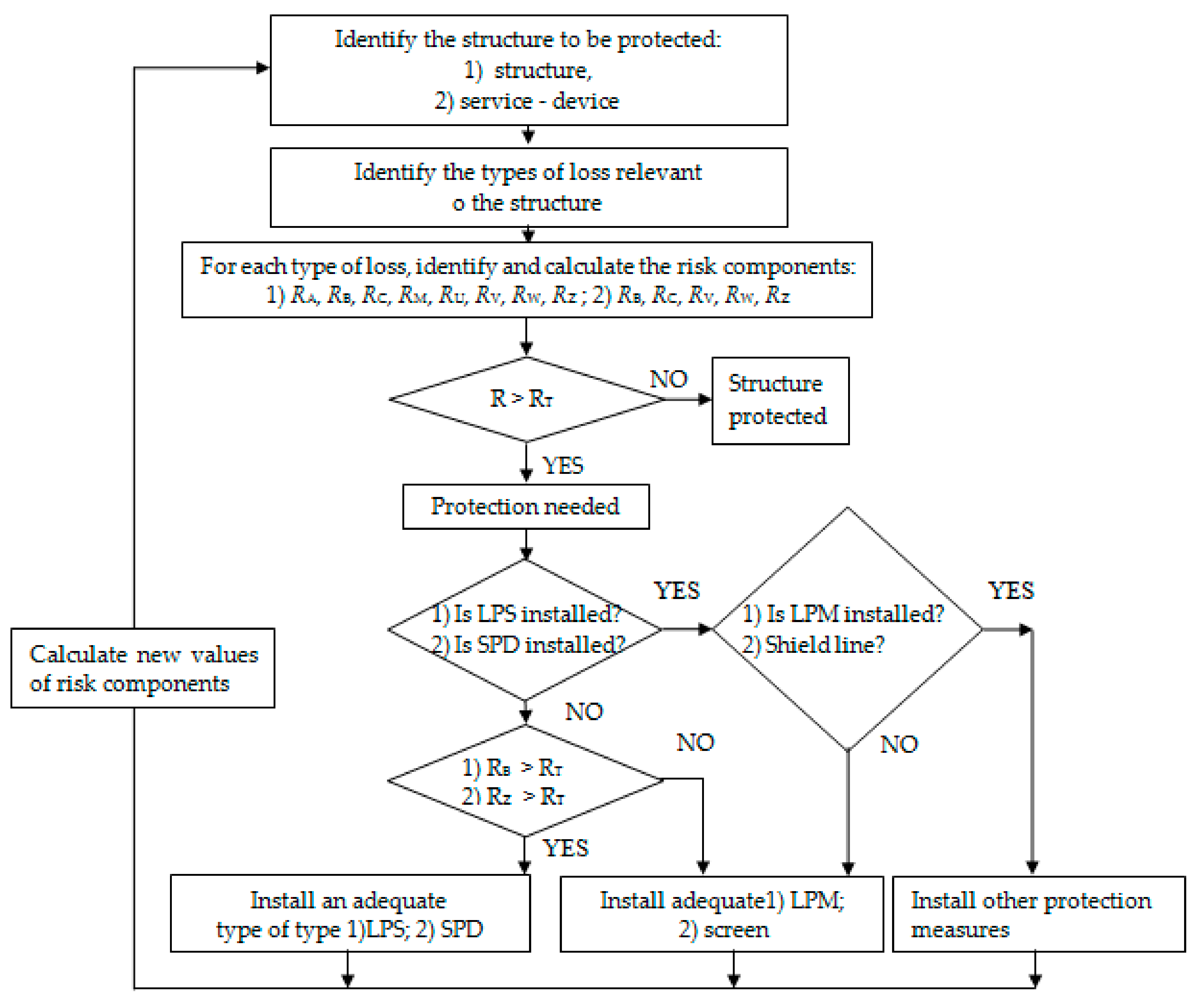
Figure 1 shows the algorithm of procedure for selecting lightning protection measures, with a specification for (1) a structure and (2) for a service device.
Measures taken to protect internal systems against the effects of LEMP, LPS—lightning protection system [
18].
The risk components for a service device can be determined, from the general equation, as:
The included designations in Equation (4) are:
- -
— number of dangerous events per year;
- -
—probability of damage to a structure;
- -
—consequent loss.
is related to the density of impacts per km2 of earth. It can be concluded that one event occurring once every 100 years does not require protection. However, it depends on the user of the facility. In the case of rtc devices, surge protection is necessary, but the amount of money that should be invested in it may be a problem.
The annual number of hazardous events
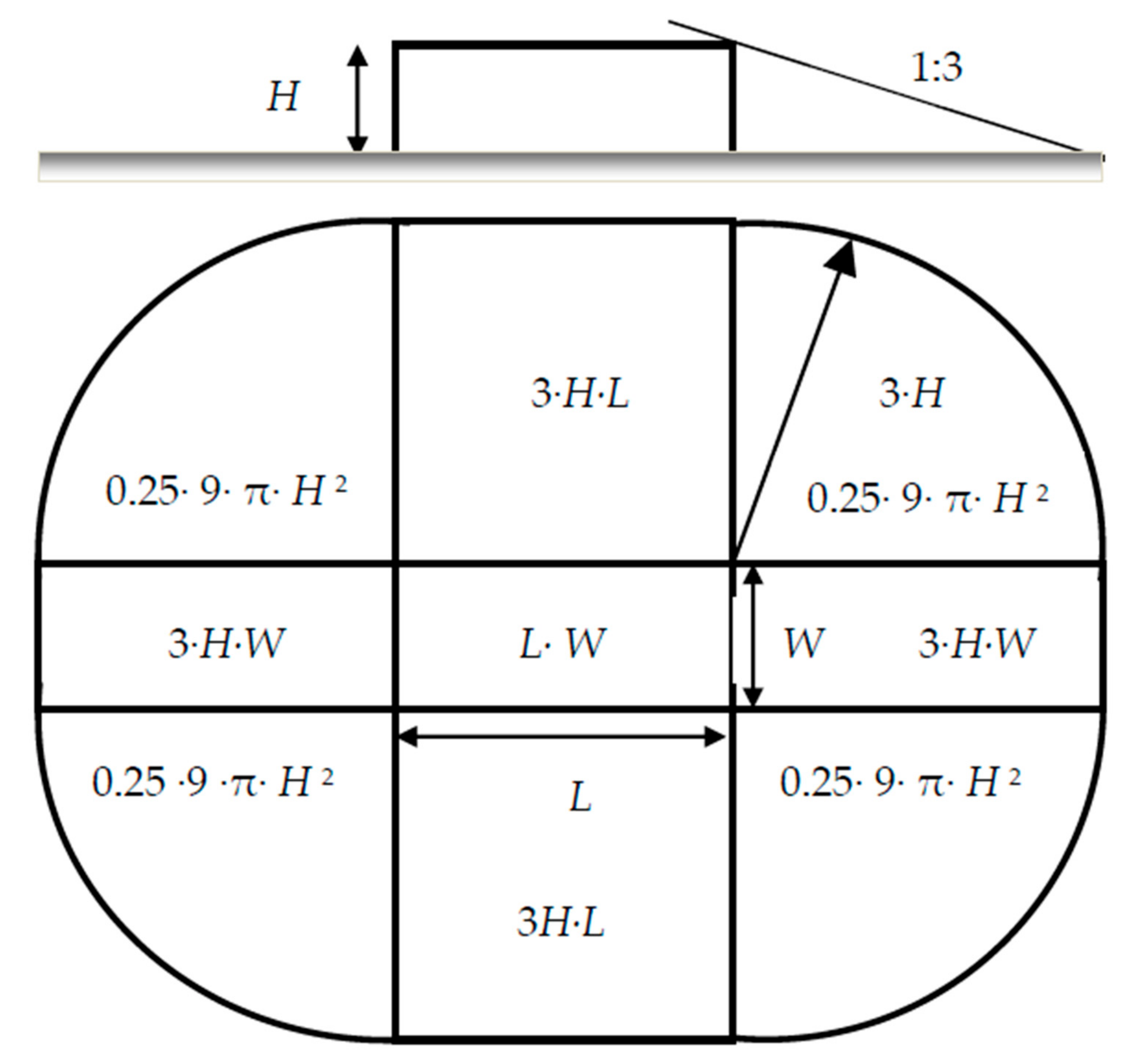
NX is closely related to the physical properties of the facility, to the equivalent area of lightning discharge collection by the facility, and to storm activity in the area where the protected facility is located. The object properties affecting the annual number of hazardous events are its location, surroundings, and the presence of a transformer in the facility’s service equipment. The equivalent lightning discharge collection area denoted as
AD, is defined as the area contained in a plane at ground level at the base of the object. It is bounded by a straight line with a slope of one-third. The line is tangent to the upper surface of the object and revolves around it. The equivalent collection area depends on the dimensions of the object and its shape. A graphical interpretation of the equivalent discharge collection area in an isolated object is shown in
Figure 2.
The average annual number, N, of serious events as a result of lightning flashes affecting the protected structure depends on the storm activity of the area in which the structure is located and on the physical properties of the structure. In order to estimate the number N, we multiply the density of lightning flashes by the equivalent discharge area for a given structure. Correction factors for the physical properties of the structure must be taken into account. The lightning flash density measures the number of lightning flashes per km2 per year.
The expected number of dangerous events
ND at the analyzed structure can be determined by
where
is the lightning ground flash density (1/km
2 × year), and
is the collection area of the structure (m
2), given by taking into account its length
, width
, and height
(as for a rectangular structure) [
18]:
The relative position of a structure, taking into account the influence of surrounding structures, is determined by the coefficient , which takes the values:
- -
0.25 for the structure surrounded by taller structures or trees;
- -
0.5 for the structure surrounded by structures or trees of the same height or smaller;
- -
1 when there are no other structures nearby;
- -
2 when the analyzed structure is isolated on the top of a hill.
The average annual number of severe events
NM resulting from discharges near the structure can be estimated from the formula:
If NM < 0, then NM = 0 should be taken.
The collection area of flashes striking near the structure
AM (m
2) is then determined from the formula:
The average annual number of dangerous events to flashes to a line is determined by
where:
- -
—number of overvoltages of amplitude not lower than 1 kV (1/year) on the line
- -
—collection area of flashes striking the line (m2)
- -
—installation factor of the line (Table A.2 [
18])
- -
—environmental factor (Table A.4 [
18])
- -
—line type factor (Table A.3 [
18])
- -
—length of the line section (m).
The value of average annual number of dangerous events
NI can be determined by:
where the collection area for flashes near a line can be estimated from the formula:
The risk (
R) is the sum of its components. Its total sum can be represented by the relationship
where:
- -
—the risk of hitting the object directly, and
- -
—risk of being struck by nearby lightning.
For the method used, the probability (with the assumptions presented above) is equal to 1, i.e., the damage is certain when no protection is applied. The use of protection measures reduces the probability appropriately, leading to the reduction in the respective risk component in question. Measures to reduce the risk include a lightning protection system, surge arresters (SPD, surge protection device), a transformer at the entrance of the line to the structure, screening of lines and wires, and the use of measures to limit the spread of fire [
18].
The last factor of Formula (4) (i.e., the loss) depends on its type and the type of damage-causing it (D1, D2, and D3). The following symbols are used to denote losses resulting from the following damage:
- -
—shocks at touch and step voltages;
- -
—physical damage;
- -
—failure of internal systems.
The decision to apply lightning protection requires determining the value of R and comparing it with the value of the tolerable risk RT. The tolerable risk value is assumed to be equal to:
- -
= 10−5 when the damage may cause loss of human life, and
- -
= 10−3 for the risk of losing public services or cultural heritage.
In other cases, the determination of RT should be performed by relevant design institutions. No tolerated value is assumed for the risk of loss of economic value. It is necessary to assess the economic sense of protection, taking into account the value of the protected structure.
In point 3.1.31 of the standard [
18], the risk value (
R) is defined as the probable average annual loss (people and goods) due to the effect of lightning in relation to the total value (people and goods) of the protected object. The risk analysis gives an estimate of the threat appearing as a result of earth lightning flashes in the structure or the service device. It takes into account not only the threat to living creatures and material losses due to direct lightning strikes but also the influence of nearby discharges [
2,
3]. The influence of these discharges on installations in the building or devices connected to it (in the forms of connection led and induced) is also significant [
4,
5]. On the basis of the performed risk analysis, we can come to a decision about the use of protection resources in order to minimize losses in the structure or the service device. Performing risk analysis provides us with the possibility of selecting protection resources that best fit the given structure type, its equipment, and its use.
The risk assessment also makes qualification of the proper level of the lightning protection for the structure (LPL, Lightning Protection Level) possible, as well as the creation of a complex conception of protection against LEMP (Lightning Electromagnetic Impulse) through the use of shielding. In the performed analysis, the chosen structure was a Signal box (St), along with the attached computer rtc devices and the feeding line, mast, two telecommunication lines, three railway automatic level crossings, and two at the farthest signals [
33].
The characteristics of the structure and the applied protection measures may affect the value of individual risk components. The table below presents the possibilities of influencing individual risk components (
Table 2).
3. Description of the Structure and Its Environmental Parameters
In the risk assessment according to the standard [
18], one of the basic parameters is the density of ground lightning flashes
Ng. This is the number of direct ground lightning discharges per km
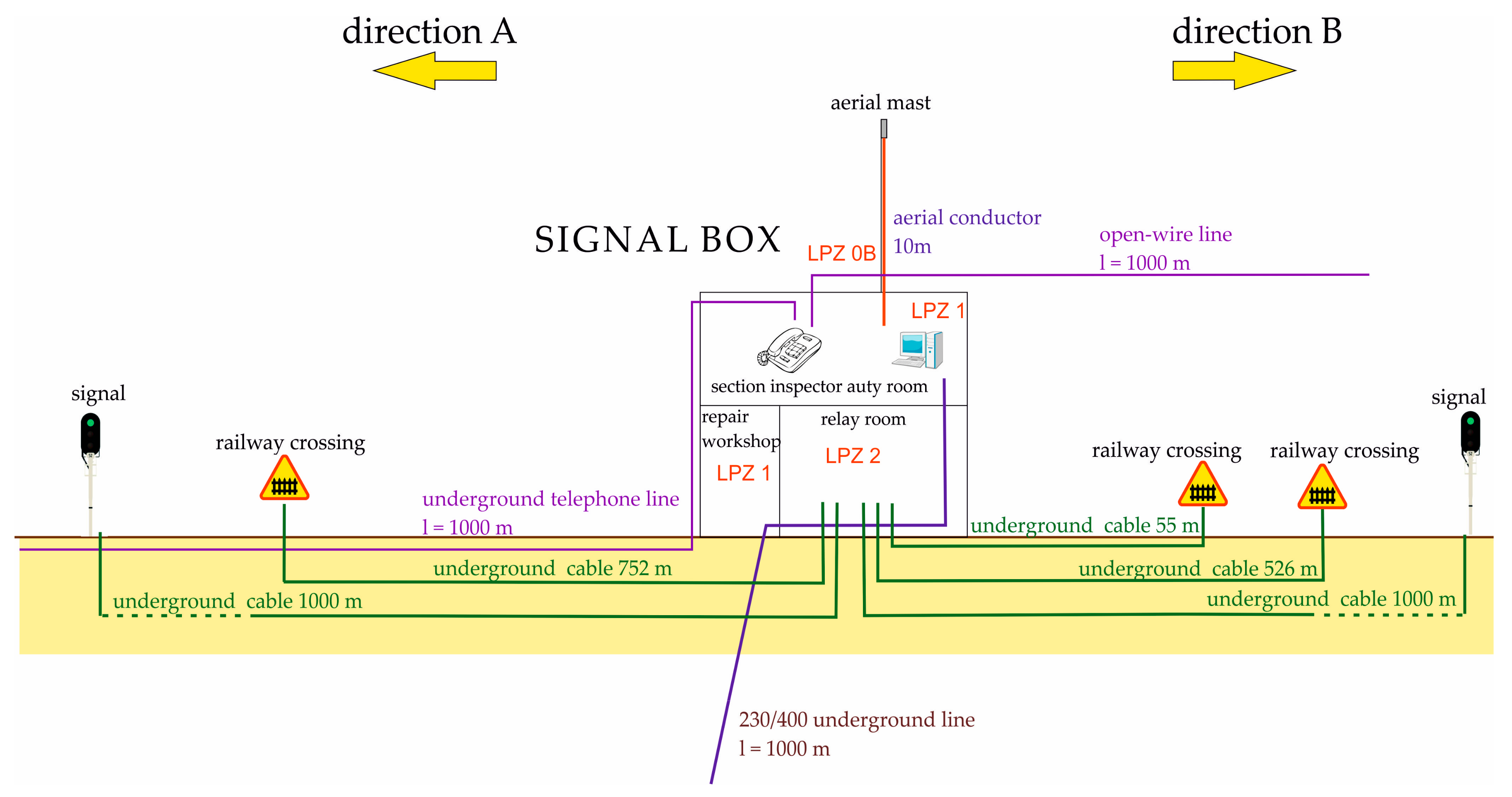
2 per year. For the area where the structure is located—the signal box (St) (
Figure 3), based on the lightning earth discharge density map [
12], the value of
Ng is 2.7 lightning flashes per km
2 per year.
Measurements of the object are important elements determining the risk of direct and indirect lightning strikes. From them, the collection areas are determined. For the analyzed case following were taken into account: length (Lb), 11.2 m; width (Wb), 5.07 m; height (Hb), 8.4 m; highest point of the structure (Hpb), 11 m.
The environment around the object is a significant factor for the number of possible direct and indirect lightning discharges. For the analyzed object St, the relative position was determined to be 1 for the Cdb coefficient. If the density of lightning ground discharges relates to the size and environment of the object, the frequency of lightning discharges should be expected:
- -
Direct to the structure ND = 0.0092 strikes/year;
- -
Indirect ones near the structure: N M = 0.543 strikes/year.
3.1. The Lightning Protection Zones of the Analyzed Structure
When designating the zones in the structure, the following factors were taken into account: The type of floor or ground, the existence of fireproof partitions and spatial screening, the arrangement of the internal systems used, installed or envisaged means of protection, and losses. Lightning Protection Zone (LPZ) zones are zones for which a lightning electromagnetic environment has been defined. The boundary of the LPZ is not always the physical boundary of an object such as a wall, floor, or ceiling [
18]:
LPZ0B—means the structure protected against the effects of a direct lightning strike:
- -
Z 1—outside the structure St;
- -
Z 2— antenna mast.
- -
LPZ1—internal zone of the protected structure:
- -
Z 3—room for duty traffic;
- -
Z 4—repair workshop room.
- -
LPZ2—room/device in LPZ1 with screen properties:
- -
Z 5—relay room.
Lightning protection zones are defined in the standard [
18] as:
LPZ0B—Protection against direct lightning strikes. Danger from part of the lightning current and its total electromagnetic field. Other internal systems are exposed to a part of the lightning current.
LPZ1—Lightning current is limited by its distribution and by the SPD at the zone boundary. Electromagnetic field damped by spatial shielding.
LPZ2… n—The current pulses are further limited by their division and by additional SPDs at the zone boundary. The electromagnetic field is generally suppressed by additional spatial shielding.
3.2. Lines Entering and Cables within the Structure
The signal box St with lines leading to and from it was assumed for the analysis [
10,
18,
31,
32,
33,
34]. For this type of analysis, conductive pipes are not considered when connected to the main earthing bar. When the pipes are not earthed, they are included in the risk analysis according to the equipotential bonding requirements. The following lines were adopted for the risk analysis for the St structure: electric AC 230/400 V, telecommunication (TLC 1 and TLC 2), antenna cable, signal cables for crossings (1, 2, and 3), and signal lines of signals (1 and 2). For every line were evaluated: the kind of the line (overhead/underground), the length of the line (outside of the structure), the environment, the connected structure to the line, the type of the internal cabling (shielded/unshielded), and the withstand voltage of equipment (the strength of receiving devices) as shown in
Table 3.
3.3. Fire Hazard
The risk of fire is a significant criterion for defining the class of lightning protection applied for a given object. When grading the fire risk, the specific fire load values defined in the standard [
18] are taken into account. The level of fire load is determined by a fire protection specialist or after consultation with the object owner or with the opinion of the object insurance company. For the selected object St, the fire risk was defined as normal. Taking into account the number of people usually present in building St in zones Z1 and Z2, no particular risk was assumed. For zones Z3, Z4, and Z5 a low level of panic was assumed (as for the number of people below 100).
3.4. External Spatial Shielding
Spatial shielding extinguishes the electromagnetic field which appears during strikes into or near the building, thus limiting induced surges in the internal installations. This is how the equalizing connection net is formed, in which all conductible parts of the building and of its internal systems are taken into account. For the external/internal spatial shielding, there was only a part of the building which featured a shielding structure. Therefore, in the analysis, a lack of shielding was noted.
4. The Risk Analysis and Choice of Protection Measures
The analysis was performed for the EN 62305-2.2008 standard. The annex to the EN 62305-2 standard [
18] contains a simplified calculation software for risk analysis developed by the TC 81 IEC working group. This software, called the IEC Risk Assessment Calculator, does not take into account all of the parameters included in the text of the standard. An alternative software version of the simplified RAC risk calculation software, with the working name ALRISK (Alternative Lightning Risk Calculation Software), has been developed at the Warsaw University of Technology [
25]. There are many commercial programs developed by DEHN [
35], OBO, as well as Spanish, Portuguese, and American companies.
In the analysis, we marked the risks R1, R2, and R4. For the risk R1, the loss of human life for persons inside and outside of the control room which contains the St, it was assessed that, in the case of a lack of protection, the risk R1 was 5.29 × 10⁻⁵; over five times the tolerable value (RT = 1 × 10⁻⁵).
Therefore, it was considered necessary to use measures (i.e., lightning and surge protection) to reduce this risk. After the use of the risk protection,
R1 dropped to the value of 3.50 × 10
−6, which was considerably less than the tolerance value. The results of the
R1 risk analysis are summarised in
Table 4.
The risk R
2 (the loss of public service) for the control room containing St, was assessed in terms of the tolerance value
RT = 1 × 10
−3 (
Table 5). The appointed risk
R2 was evaluated as 4.54 × 10
−3 under the lack of protection while, with the use of protection measures, the risk
R2 came down to the value of 8.6 × 10
−4.
The value of R4 determines the reduction in risk is estimated to reduce economic losses given the current and expected status. The result of such calculations is an economically justified cost of protection measures in relation to the value of the structure.
The
CLZ loss cost can be derived from the subsequent formula
where
R4Z—risk related to a loss of value in an area where no protection measures are applied and
ct defines the total value of the structure (building, content with internal systems installed, and their activities in currency).
The cost of the total loss of
CL in the structure is obtained [
18,
19] from the formula
where
is the risk associated with loss of value without application of protection measures.
CRLZ, defined as the cost of residual losses in an area despite the application of conservation measures, is designated by means of the following equation
where
R’
4Z is the risk determining the loss in the zone, taking into account the application of protective means.
The total cost C
RL of the residual loss in the structure despite the protective measures can be obtained from the subsequent equation
where
R’4 = Σ
R’4Z is the risk connected with the loss of value in the structure with protection measures.
The cost per year
CPM of protection means may be calculated using the following formula
where
The saving (SM) per year in money is:
Protection may be justified for an annual savings of SM > 0.
Determination of the R4 level was made taking into account: i—interest rate: 1.1%, at—amortization period: 10 years, a—depreciation rate 10%, and m—service rate 1.1%.
The value of the costs of the analyzed structure was converted from PLN to EUR (1EUR = 1 PLN/4.5). For the qualification of costs of the building, we took into account one year’s cost of the building (
CB), which was 65,744.89 EUR; the cost of the content (
CC), 1,207,656.44 EUR; and the cost of the systems in the structure (C
S), 1627.22 EUR [
1]. The single cost of protection resources was accepted as 2222.22 EUR. As a result of the estimation of the risk R
4 (
Table 6), the entire cost of losses on account of lightning in the case of the lack of protection measures
CL was 3684.07 EUR/year. The cost of residual losses
CRL on account of lightning in the case of the presence of chosen protection measures was 239.50 EUR. One year’s cost of chosen protection resources
CPM in an acceptable period of amortization of 10 years was, thus, assessed as 271.11 EUR/year. One year’s savings under the use of the chosen protection measures was, thus, 3173.4 EUR/year [
1].
Therefore, the use of the chosen protection measures is economically well-grounded. The denominative analysis of the level of the risk R4 did not seem necessary, in the case of the estimation of the chosen structure St, as we did not receive significant differences as a result of carrying it out. For example, repeated analyses were carried out with single costs of protection resources of 1111.11 EUR and 3333.33 EUR. One year’s savings under the use of chosen protection resources carried out properly were 3037.91 EUR/year and 3309.01 EUR/year, respectively. The plan of 1111.11 EUR is more reliable, as confirmed by higher savings.
The values taken into account when determining the R4 level were taken into account: i—interest rate: 1.1%, at—amortization period: 10 years, and—depreciation rate 10% and m—service rate 1.1%.
Figure 4 shows the results of the analysis performed for the assumed longer amortization period of 50 years, the cost of funds allocated for protection 4444.44 EUR, and for various values of i—interest rate and m—service rate. The largest increase in savings occurs in the initial period, up to 10 years. Later, these values increase much more slowly.
The next
Figure 5 shows the savings results for the amortization rate from 2%–20% and other data, as for the results of the analysis in
Figure 4.
Lowering the risk level to an acceptable value can be achieved by an appropriate selection of protection measures. Such a selection of measures is part of the risk management for the analyzed structure St and is appropriate only for the selected type of structure and its surroundings. The final part of the measures includes protection measures that should be applied to ensure the protection of the analyzed structure, including protection zones [
13,
26].
Table 7 presents the results of the analysis of the number of stormy days’ impact on the change in the values of risk
R1 and
R2 and indicates the need to take into account the actual number of days. The calculated risk value for the analyzed object higher than the tolerated value obliges the designer to provide additional lightning protection measures in order to reduce this risk.
The calculated risk values for the analyzed structure 1.27 × 10
−3 and 1.59 × 10
−3 (
Table 7) are higher than the tolerated value. This obliges the designer to provide additional and better lightning protection measures to reduce this risk.
Table 8 presents the results of the cost change analysis for risk
R4, taking into account the impact of the number of stormy days. These trends are taken into account in the consecutive sheets of the standard. The aim is to increase the accuracy in determining the actual factors closely related to the specificity of the terrain and the number of stormy days.
5. Conclusions
The continuous operations of computer RTC devices require the reliable transmission of transmitted data and signals. Unauthorized access, malware, overvoltages caused by lightning strikes, or switching overvoltages may pose threats to the network. These are especially dangerous for wires extending outside of the signal box building.
In this paper, we analyzed the risk of damage caused by overvoltages of atmospheric origin in rtc devices connected to a signal box in which digital devices are installed. Our analysis showed that the risk flowing to the structure from the side of the tracks to lines supplying the RTC devices is much greater in the case of structures located in rural and suburban areas. Additionally, the non-traction lines were not protected by ground wires. This condition poses a very high risk for RTC devices as, for example, the amplitudes of voltages induced in wire loops arranged inside the structure during a direct lightning stroke can reach the values of tens of kV. As a result of the analysis, it was shown that each applied protection method influenced its risk level. Properly selected surge arresters should depend on the least favorable connection solutions that may occur in a given installation. It is particularly important to apply appropriate protection measures, including securing the wires of lines leading to the signal box St structure and those connected with computer devices. These circuits are the most vulnerable to damages due to atmospheric surges. Every mistake made in designing appropriate protections or their installation may result in damage to the devices and additional repair costs. Most important, in this regard, is the correct operation of devices and systematic control of the applied lightning and overvoltage protection measures. The publication includes verification of the applied lightning and overvoltage protections with those recommended as a result of the risk assessment. The lightning protection measures described in the EN 62305 series are not mandatory when used in traction systems.
The publication comprises the verification of the applied lightning and overvoltage protections with those recommended as a result of the risk assessment. As a result of the analysis, an unprotected internal circuit with a supply voltage of 24 V DC was found, through which the overvoltage leaked and significantly damaged digital devices.
The presented analyzes may be useful in the risk assessment for the designed RTC devices. This will create better conditions for the failure-free operation of railway devices.


