Article

Experimental Study on Dynamic Combustion Characteristics in Swirl-Stabilized Combustors

School of Mechanical Engineering, Chungbuk National University, Chungbuk 28644, Korea
*
Author to whom correspondence should be addressed.
Energies 2021, 14(6), 1609; https://doi.org/10.3390/en14061609
Submission received: 10 February 2021 / Revised: 9 March 2021 / Accepted: 9 March 2021 / Published: 14 March 2021
(This article belongs to the Special Issue Propulsion and Combustion in Aerospace Systems)

Abstract

:
An experimental study was performed to investigate the combustion instability characteristics of swirl-stabilized combustors. A premixed gas composed of ethylene and air was burned under various flow and geometric conditions. Experiments were conducted by changing the inlet mean velocity, equivalence ratio, swirler vane angle, and combustor length. Two dynamic pressure sensors, a hot-wire anemometer, and a photomultiplier tube were installed to detect the pressure oscillations, velocity perturbations, and heat release fluctuations in the inlet and combustion chambers, respectively. An ICCD camera was used to capture the time-averaged flame structure. The objective was to understand the relationship between combustion instability and the Rayleigh criterion/the flame structure. When combustion instability occurred, the pressure oscillations were in-phase with the heat release oscillations. Even if the Rayleigh criterion between the pressure and heat release oscillations was satisfied, stable combustion with low pressure fluctuations was possible. This was explained by analyzing the dynamic flow and combustion data. The root-mean-square value of the heat release fluctuations was observed to predict the combustion instability region better than that of the inlet velocity fluctuations. The bifurcation of the flame structure was a necessary condition for combustion instability in this combustor. The results shed new insight into combustion instability in swirl-stabilized combustors.

1. Introduction

For decades, conventional gas turbine engines used for electric power generation have mainly employed diffusion-flame-type combustors because of their high reliability and stability [1]. However, this type of combustion causes high temperatures in the local flame zones, increasing the formation of thermal NOx and soot. Recent gas turbine engines have often been operated under lean premixed or partially premixed conditions, to overcome increasingly stringent emission regulations [2,3]. However, self-excited thermo-acoustic instability is likely to occur under fuel-lean premixed conditions. Combustion instability can lead to structural defects or failures in the combustor, in addition to severe problems in terms of heat transfer and combustion efficiency.
When unsteady heat release fluctuations are coupled with pressure perturbations, the pressure oscillations are amplified up to the periodic limit cycle and are self-sustained. The necessary condition for this phenomenon was provided by Rayleigh [4] and is summarized as follows:
V T p ( x , t ) q ( x , t ) d t d v > 0
where p , q , T, and V are pressure fluctuation, heat release fluctuation, time interval, and volume, respectively. Equation (1) is called the initial Rayleigh criterion and has been used for understanding combustion instability [5,6,7].
Nagarajan et al. [8] examined the effect of the inlet flow turbulence intensity on the characteristics of combustion instability. They indicated that the combustion system satisfied the Rayleigh criterion during thermo-acoustic instability, that is, the phase difference between the heat release and pressure fluctuations remained within 90° for high-amplitude oscillations. Using the Rayleigh index distribution, Venkataraman et al. [9] observed that the driving region of the instability moved as the inlet velocity changed. Allison et al. [10] investigated the acoustic behavior of combustion instability in a dual-swirl burner by changing the fuel properties, air flow rate, and burner geometry. They suggested that the 2-D Rayleigh index is a good indicator of the location of the amplified instability, which depends on the flame structure and fuel composition. Geraedts et al. [11] represented the 3-D Rayleigh index fields in complex swirl-stabilized flames by measuring high-repetition-rate OH* chemiluminescence.
However, the initial Rayleigh criterion is not a sufficient condition for combustion instability. This is because it does not contain terms representing the acoustic energy loss and fluctuation energy related to entropy [12,13,14]. Kim [12] observed that high-amplitude velocity fluctuations and heat release oscillations coexisted without the pressure oscillation–heat release fluctuation coupling process. They also confirmed that equivalence ratio nonuniformities played a major role in instability feedback mechanisms, and that the initial Rayleigh criterion was a weak necessary condition for self-excited combustion instability. Yoon et al. [13] investigated the relationship between combustion instability and flame structure under various operating conditions. They noted that the characteristics of combustion instability at a high inlet velocity were well explained by the initial Rayleigh criterion, but the unstable combustions at a low inlet velocity were out-of-phase between the pressure and the heat release oscillations. Nicoud and Poinsot [14] analytically showed that both the initial Rayleigh criterion and the extended Rayleigh criterion, including the acoustic energy loss equation, were insufficient to describe combustion instability. They argued that the fluctuation energy equations should be used as a new criterion for thermo-acoustic instabilities. However, the experimental measurement of properties such as acoustic energy loss and entropy fluctuation energy is almost impossible.
Sarli et al. [15,16] showed that oscillations in swirl-stabilized combustors may be different in nature: they may originate from system instabilities (feed mixture instability) or from the propagation to the whole combustor of the flame intrinsic oscillations due to heat losses (thermo-kinetic instability). Whatever the driving mechanism (system or flame instability), a whole acoustic mode is excited and, accordingly, Rayleigh′s criterion is always verified. Conversely, the restatement of Rayleigh′s criterion based on the time-delay approach is verified only for the oscillations originated from system instability, while it fails with the thermo-kinetic oscillations, thus providing a way to discern between the different mechanisms.
The first objective of the present study is to investigate the effects of flow and geometric conditions on the dynamic combustion characteristics of swirl-stabilized combustors. The second objective is to understand experimentally how the initial Rayleigh criterion is related to combustion instability and its limitations. The third objective is to confirm the relationship between the bifurcation of the flame structure and combustion instability.

2. Experimental Methods

2.1. Experimental Set-Up and Instrumentation

A schematic diagram of the swirl-stabilized combustor experiment rig is shown in Figure 1. The swirl-stabilized combustor consisted of an inlet mixer and a combustion chamber. The inlet mixer was 300 mm long and had a circular inner cross-section with a diameter of 30 mm. Air and fuel were supplied 35 mm downstream of the closed bottom of the inlet. Their mass flow rates were controlled using a calibrated choked orifice (O′Keefe Controls Co.) and a mass flow controller (MKP, VIC-D220, uncertainty ±1%). A honeycomb was installed 150 mm downstream of the inlet bottom to reduce the velocity fluctuations in the premixed gas and provide a uniform flow. An axial swirler was mounted 25 mm upstream of the dump plane. Depending on the experimental conditions, one of the three axial swirlers with the vane angles of 30°, 41°, and 53° was used. Their swirl numbers (SNs; defined as the ratio of tangential momentum to axial momentum) were calculated to be 0.43, 0.65, and 0.99, respectively [17]. The combustion chamber has a square inner cross-section of dimensions 75 mm × 75 mm. Its length was set to 320 and 95 mm to investigate the effect of the longitudinal resonant frequency. Two quartz windows were attached to the stainless-steel frame body of the combustion chamber for optical access.
Two piezoelectric dynamic pressure sensors (uncertainty ±1%) were flush-mounted 25 mm downstream and 125 mm upstream of the dump plane, and the pressure fluctuations in the combustion chamber and inlet were measured. The pressure fluctuations were amplified using a signal conditioner (PCB Piezotronics, 482A16). A probe of a hot-wire anemometer (HWA, TSI, 1201-6) was installed 75 mm upstream of the dump plane, and the flow velocity fluctuations in the inlet were detected. A photomultiplier tube (PMT, Thorlabs, PDA100A-EC) covered with a 431.5 ± 5 nm bandpass filter was used to collect the heat release fluctuations from the flames simultaneously [18,19,20]. An ICCD camera (Andor, DH334T-18U-03) with the same filter was employed to acquire CH* chemiluminescence images and was set to an exposure time of 2 ms. Twenty images were acquired and time-averaged for each experimental condition. An exposure time of 2 ms was close to one cycle of the pressure oscillations in this combustor. Therefore, the time average of twenty images was enough to observe the macroscopic flame structure. Five K-type thermocouples (uncertainty ±1.5 K) were placed 30 mm apart on the side-wall of the long combustion chamber, and three thermocouples were placed in the short chamber. The measured data signals were written to NI-cDAQ for 1 s at a sampling rate of 10 kHz.

2.2. Experimental Conditions

The experimental conditions, including the flow conditions and geometric parameters, are listed in Table 1. These conditions are known to influence the combustion stability in swirl-stabilized combustors [21,22,23,24]. Hot-firing tests were performed by independently varying the experimental conditions. The inlet flow mean velocity ( u ¯ ) was chosen to study the behavior of turbulent premixed flames. The equivalence ratio (ϕ) was selected to exclude the regions of flame extinction and flashback. Two combustion chambers of different lengths and three axial swirlers with different SNs were utilized to examine their effects on the combustion stability in the swirl-stabilized combustor.

3. Results and Discussion

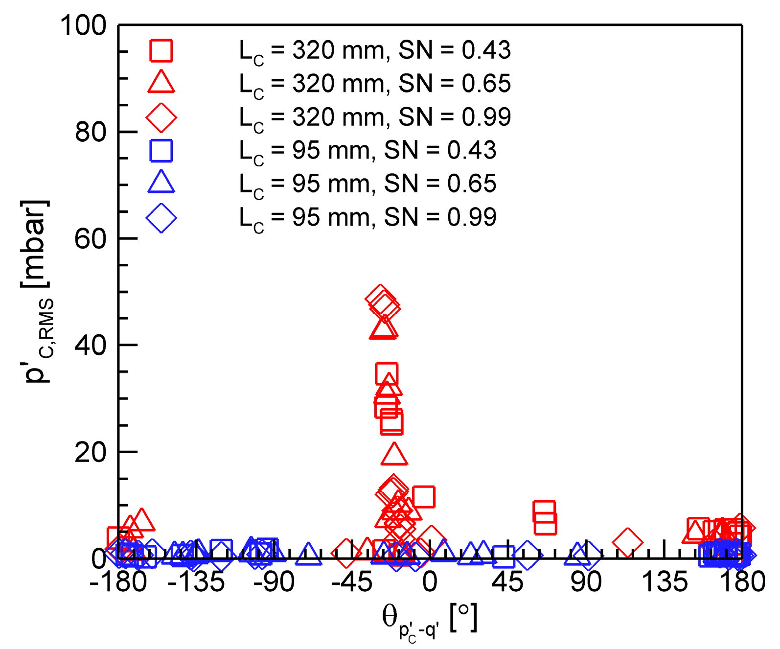
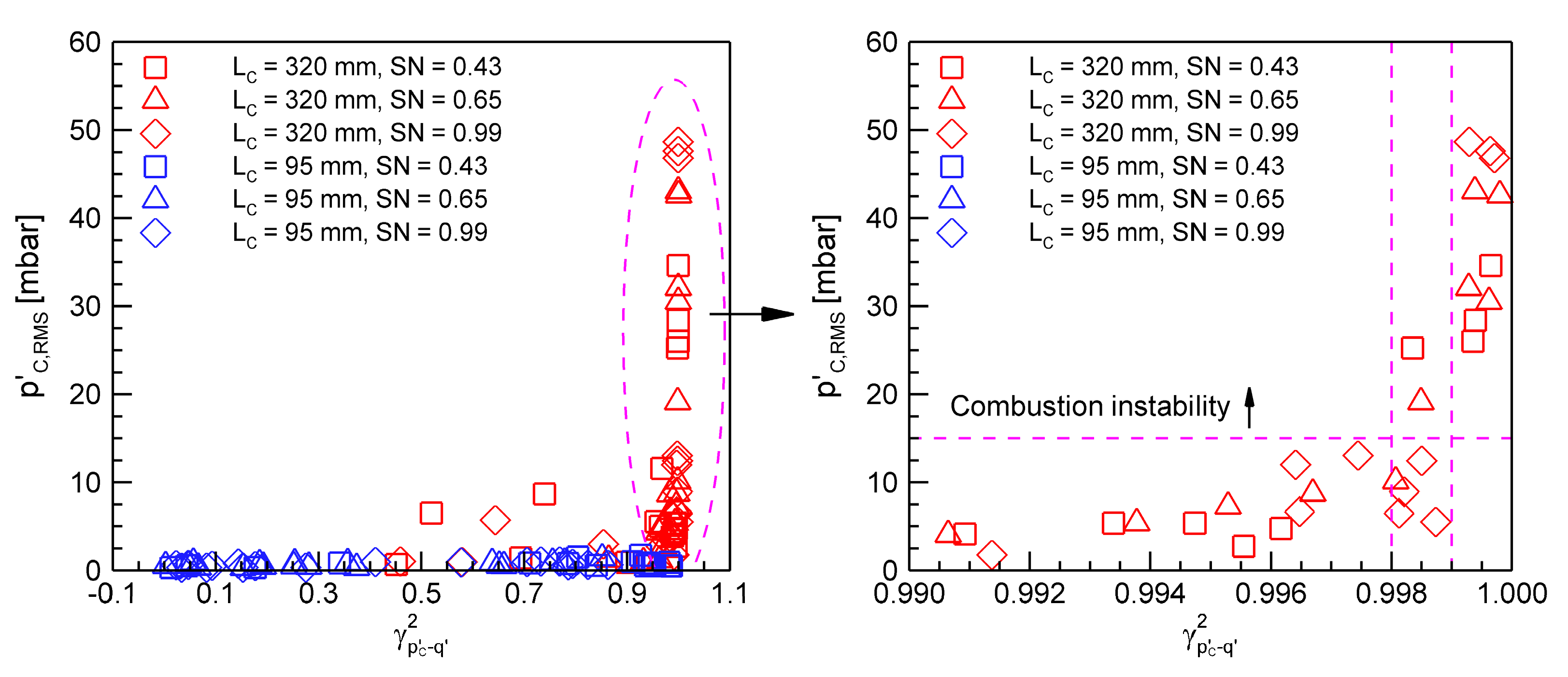
3.1. Definition of Combustion Instability

The dynamic pressure, heat release, and inlet velocity data were sampled at 10 kHz and were digitally filtered using a bandpass filter of cut-off frequencies 130 and 2000 Hz to eliminate the noise components and direct current. The root-mean-square (RMS) values ( p C , R M S ) of the filtered pressure fluctuations measured in the combustion chamber are plotted in Figure 2 as a function of the phase difference ( θ p C q ) between the pressure fluctuation and the heat release fluctuation ( q ). The RMS value rises sharply only when the phase difference is in-phase ( 0 ° | θ p C q | < 90 ° ). However, despite the in-phase conditions, stable combustion occurred in several cases in the 320-mm-long combustion chamber, and no significant pressure oscillations were observed in the 95-mm-long chamber. The results show that the initial Rayleigh criterion is a necessary but not sufficient condition for the onset of combustion instability [12,13].
Figure 3 shows the filtered pressure, heat release, and inlet velocity fluctuation data for the cases of LC = 320 mm, SN = 0.43, u ¯ = 15 m/s, and ϕ = 0.55 and 0.80. At ϕ = 0.55, the dynamic combustion characteristics were chaotic at the noise level without any special pattern, and the phase difference ( θ p C q ) was out-of-phase over time. Thus, their values were much lower than those at ϕ = 0.80. At ϕ = 0.80, the pressure, heat release, and inlet velocity fluctuations were amplified several times and synchronized at the same frequency. They oscillated in a sinusoidal shape, although the pressure ( p I n l e t ) and velocity ( u ) fluctuations were slightly distorted owing to the flow turbulence and reflected pressure waves in the inlet. The inlet velocity oscillations preceded the pressure ( p C ) and heat release ( q ) fluctuations in the combustion chamber. This phenomenon can be explained by the principle of the limit cycle of thermo-acoustic combustion instabilities commonly observed in ducted flames [25]. As expected, the phase difference ( θ p C q ) was in-phase, and the phase difference ( θ p C p I n l e t ) was out-of-phase.
The power spectral densities (PSDs) of the pressure fluctuations corresponding to the cases in Figure 3 are presented in Figure 4. At ϕ = 0.55, the PSD data display no dominant frequencies. In contrast, when the equivalence ratio increased to 0.80, the resonant frequency of the first longitudinal mode of the combustion chamber length was approximately 345 Hz, and its harmonic frequencies were visible in both the inlet and combustion chamber. The occurrence of combustion instability can be characterized by a strong, steep peak at a specific frequency. The experimental results show that a strong, steep single peak and its harmonic frequencies could be observed in the PSD plot when the RMS value of the pressure fluctuations in the combustion chamber was greater than approximately 15 mbar. Thus, a p C , R M S of 15 mbar was selected as a criterion for the onset of combustion instability. As the swirl-stabilized combustor is of open type, the pressure in the chamber can be assumed to be atmospheric pressure. Therefore, the criterion can be defined as 1.5% of the chamber pressure, as in previous studies [26].
The effects of the inlet mean velocity, equivalence ratio, SN, and combustion chamber length on p C , R M S in the present swirl-stabilized combustor are shown in Figure 5. In the case of the 320-mm-long combustor chamber, combustion instabilities were observed as the inlet mean velocity and equivalence ratio increased, because the high combustion power fed more energy to the pressure waves in the acoustic resonant modes. Lieuwen [27] also observed that the inlet velocity had a significant effect on the amplitude of oscillations over whole experimental conditions. Venkataraman et al. [9] showed that when the equivalence ratio increased, the widened flame due to the higher flame speed interacted with the vortex structure, leading to unstable combustion. Although the combustion instability area became compact, the strength was the highest at SN = 0.99. As can be expected from Figure 2, no combustion instability was observed in the shortened combustion chamber of length 95 mm, and the p C , R M S was less than 1.8 mbar in all the cases. The frequency of the first longitudinal mode was calculated to be above 1000 Hz. It is believed that the flow and combustion dynamics in the present swirl-stabilized combustor cannot boost such high-frequency pressure oscillations.

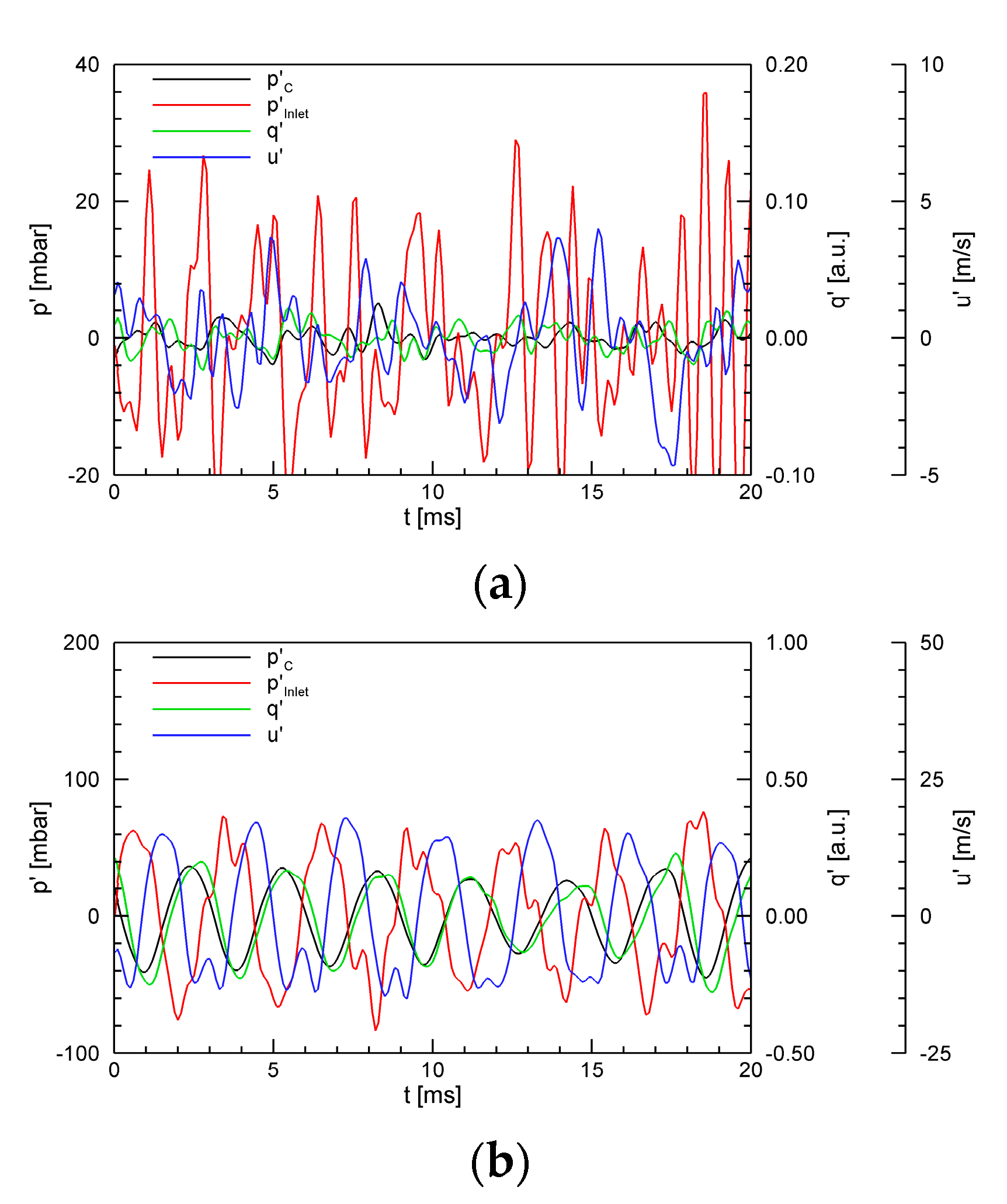
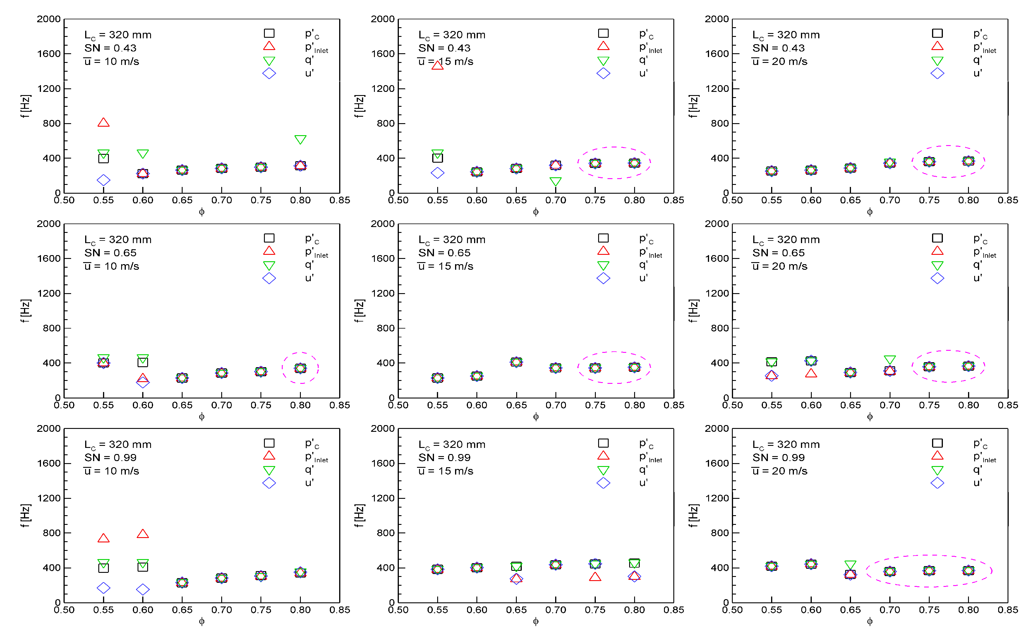
3.2. Dynamic Combustion Characteristics

The dynamic combustion behavior of the experimental results is explained in this section based on the limit cycle. The principle of the limit cycle in ducted flames is as follows: when the acoustic mode of the combustor is excited, the acoustic pressure has a high-amplitude fluctuation; the inlet flow velocity then vibrates at the same frequency; subsequently, a slightly delayed heat release perturbation occurs because the heat release is proportional to the flow rate of unburnt premixed gas; finally, the heat release oscillation becomes a source of the pressure wave and feeds back energy into the excited acoustic mode [25]. The limit cycle is dependent on the system geometry/flow condition and is characterized by nonlinear characteristics. It can also cause combustion instability in a system, unlike aperiodic or chaotic cycles [18].
All the RMS values of the filtered heat release and inlet velocity fluctuations are shown in Figure 6 as a function of the phase difference ( θ p C q ) . The velocity fluctuations were normalized by the mean velocity of the inlet flow. Comparing Figure 6a with Figure 2, the RMS values of the heat release fluctuations almost linearly coincided with those of the pressure fluctuations and peaked only in the narrow band of 30 ° < θ p C q < 20 ° . Consequently, it can be confirmed that the heat release fluctuation is a direct cause and indicator of combustion instability. For the 95-mm-long combustion chamber, the RMS values of the heat release fluctuations were very small under all the experimental conditions, similar to those of the pressure fluctuations. In contrast, the normalized inlet velocity fluctuation was always greater than 0.1 due to the turbulence of the flow itself and had large values even in out-of-phase situations.
The filtered pressure, heat release, and inlet velocity fluctuation data for the case corresponding to the dashed circle in Figure 6b are plotted in Figure 7. They all appeared to vibrate at the same frequency; however, a special relationship between p C and q can be observed. In Figure 7a, q oscillates opposite to p C , and thus, θ p C q is calculated to be 170°. In Figure 7b, the peak frequencies of the pressure and inlet velocity fluctuations are the same, i.e., 313 Hz, whereas the peak frequency of the heat release fluctuations is doubled to 626 Hz. When p C is at the local maxima, q is also at the local maxima. However, even when p C is at the local minima, q is usually at the local maxima.
For the case of LC = 320 mm, SN = 0.65, u ¯ = 20 m/s, and ϕ = 0.55, p C , R M S had a slightly smaller value of 7.3 mbar compared with the present criterion, and θ p C q at the dominant frequency of 414 Hz was −24°. The PSDs of the pressure fluctuations are shown in Figure 8a. There are two dominant peaks at 254 and 414 Hz in both the inlet and combustion chamber. Figure 8b presents p C and q filtered using two different bandpass filters of cut-off frequencies 200 and 300 Hz, and 350 and 450 Hz, respectively. p C and q are in-phase at the peak frequency of 414 Hz, but out-of-phase at the peak frequency of 254 Hz. The former would function in the direction of increasing pressure perturbation, whereas the latter would function in the opposite direction. These relationships between p C and q in Figure 7 and Figure 8 are believed to have prevented the pressure fluctuations from increasing to a limit cycle with a large amplitude of 15 mbar or more.
With the help of signal processing, the RMS values of the filtered pressure fluctuations in the combustion chamber are re-plotted in Figure 9 as a function of the magnitude-squared coherence between p C and q at the dominant frequency. The coherence is defined as a measure of linearity between two signals. The maximum value of the coherence is unity, indicating an ideal linear relationship between the two signals. Conversely, if the coherence is zero, there is no linear relationship between the two signals [18]. It is expected that the coherence function is related to combustion instability. When the coherence is between 0.99 and 1.00, p C , R M S appears to increase exponentially with the coherence. Thus, coherence can be a good index for expressing the onset of combustion instability.
The dominant frequencies of the filtered pressure, heat release, and inlet velocity fluctuation data for the 320-mm-long combustion chamber are shown in Figure 10 as a function of the equivalence ratio. The dashed ellipse indicates the cases with p C , R M S > 15 mbar. Except for a low equivalence ratio of 0.6 or less, the dominant frequencies for each experimental condition are almost the same, regardless of the sensor type or location, and increase with the equivalence ratio because of the higher combustion temperature. When combustion instability occurred, the dominant frequencies in the whole system were synchronized based on the limit cycle. However, in the case of inducing destructive interference at the second dominant peak, as shown in Figure 8b, stable combustion could be possible even if all the oscillations had the same dominant frequency. At this time, the coherence between p C and q decreased to less than 0.99 in this combustor. Not all the dynamic combustion characteristics ( p , q , u ) with the same dominant frequency caused a limit cycle with a large amplitude; however, it was evident that the prerequisite for the onset of thermo-acoustic instability was that the dynamic characteristics had to be synchronized.
Figure 11 shows the maximum PSDs of p C for the 320-mm-long combustion chamber. A comparison of Figure 11 and Figure 9 shows that the maximum PSD represents the intensity of combustion instability much more apparently than the RMS value of p C . Interestingly, the dominant frequency was concentrated in the frequency bands of 340 and 370 Hz when combustion instability occurred. According to the time lag theory [28,29,30,31], the characteristic time in the present swirl-stabilized combustor appeared to be commensurate with a period of oscillation between 1/370 and 1/340 s.

3.3. Flame Structure

The onset of thermo-acoustic instability and the bifurcation of the flame structure occur simultaneously [32,33,34,35,36]. A bifurcation refers to the qualitative change in a system with changes in system parameters [18,27]. Taamallah et al. [32,33,34] investigated the association between the onset of combustion instability and flame configuration. They observed that the onset of the unstable mode coincided with the transition in which the flame appeared in the outer recirculation zone. Fritsche et al. [36] showed an abrupt change in the position and shape of the flame during the transition from a stable flame to an unstable flame. Representative time-averaged CH* chemiluminescence images are shown in Figure 12. The left and right are the normalized and inverse Abel-transformed images, respectively. Because the signal is an integrated light from the entire flame through the line of sight, the normalized CH* chemiluminescence image cannot represent an actual reaction field. Hence, the inverse Abel transform was used to extract the radially resolved flame structure from the CH* chemiluminescence image. At ϕ = 0.55, the chemical reaction occurred only in the shear layer between the fresh reactant and the central toroidal recirculation zone established in the wake of the center body of the swirler owing to the swirling flow. As the equivalence ratio increased, the chemical reaction was completed before the reactant reached the wall with the help of a faster flame speed. At ϕ = 0.70, a flame bifurcation was observed. Some chemical reactions were observed near the central axis, with the major chemical reactions occurring in the shear layer between the reactant and the corner recirculation zone formed downstream of the dump plane. As the equivalence ratio increased further, a significant amount of chemical reaction occurred near the central axis, and the flame became compacted. However, as shown in Figure 10, the combustion instability started at ϕ = 0.80, for the case of LC = 320 mm, SN = 0.65, and u ¯ = 10 m/s. In the other cases, the flame bifurcation phenomenon occurred at an equivalence ratio equal to or lower than that of the combustion instability. In this study, flame bifurcation was a necessary condition for combustion instability, similar to the initial Rayleigh criterion.

4. Summary and Conclusions

The dynamic combustion characteristics ( p , q , u ) and flame structure of turbulent premixed flames in swirl-stabilized combustors were studied by changing the inlet mean velocity (10, 15, and 20 m/s), equivalence ratio (0.55–0.80), SN (0.43, 0.65, 0.99), and combustion chamber length (95, 320 mm). When the RMS values of the pressure fluctuations in the combustion chamber were greater than 15 mbar, the strong and steep peak was observed in the frequency bands of 340 and 370 Hz. The combustion chamber length played a critical role in the occurrence of combustion instability because it influenced the resonance frequency and determined the acoustic coupling or decoupling. Combustion instability with a limit cycle of high-amplitude pressure oscillations was concentrated in the region of high inlet mean velocities and high equivalence ratios. The SN had little effect on the instability zone, but the intensity of combustion instability was the highest at SN = 0.9.
When combustion instability occurred, the pressure and heat release oscillations were perfectly in-phase. However, the combustion was stable under several experimental conditions, satisfying the initial Rayleigh criterion. At that time, the pressure and heat release oscillations were out-of-phase at peak frequencies other than the dominant peak frequency, which served as damping. The results show that the initial Rayleigh criterion is a necessary condition, but not sufficient for combustion instability. The heat release fluctuation was a direct cause, and its amplitude was a good indicator of combustion instability. The magnitude-squared coherence between the pressure and heat release oscillations was also a good index for expressing the onset of combustion instability. Although the normalized inlet velocity fluctuations were significant, and the pressure, heat release, and inlet velocity fluctuation data had the same dominant frequency, the pressure oscillations were not amplified unless the initial Rayleigh criterion was satisfied.
The bifurcation of the flame structure occurred at an equivalence ratio equal to or lower than that of the combustion instability. Bifurcation also occurred in the 95-mm-long combustion chamber, where no combustion instability was observed. It was discovered that the bifurcation of the flame structure is not a sufficient condition in the present swirl-stabilized combustor, but is a necessary condition.
The experimental results show that the limit cycle with high-amplitude pressure oscillations had a period between 1/370 and 1/340 s. This corresponded to the longitudinal resonant frequency of the combustion chamber. However, the effect of the inlet mixer on combustion instability should not be ignored. In this paper, the dynamic characteristics corresponding to the resonance mode in the inlet mixer functioned in the direction of decreasing pressure perturbations. In light of these findings, the effect of the inlet mixer length and acoustic pressure-flow disturbance coupling on combustion instability will be studied in the future.

Author Contributions

All authors have contributed equally in the methodology, investigation, data curation, writing—original draft preparation, and writing—review and editing. All authors have read and agreed to the published version of the manuscript.

Funding

This research was supported by the National Research Foundation (NRF–2018M1A3A3A02065683 and NRF–2019M1A3A1A02076962) funded by the Ministry of Science, ICT, and Future Planning, South Korea. The authors would like to thank MSIP for their support.

Conflicts of Interest

The authors declare no conflict of interest.

Nomenclature

HWAHot-wire anemometer
LCLength of the combustion chamber
LILength of the inlet mixer
p C Pressure fluctuation in the combustion chamber
p C , R M S RMS value of the filtered pressure fluctuations in the combustion chamber
p I n l e t Pressure fluctuation in the inlet mixer
PMTPhotomultiplier tube
PSDPower spectral density
q Heat release fluctuation
RMSRoot-mean-square
SNSwirl number
TLong enough time interval
u ¯ Inlet mean velocity
u Velocity fluctuation
VVolume
γ2Magnitude-squared coherence
θ Phase difference
ϕEquivalence ratio

References

  1. Huang, Y.; Yang, V. Dynamics and stability of lean-premixed swirl-stabilized combustion. Prog. Energy Combust. Sci. 2009, 35, 293–364. [Google Scholar] [CrossRef]
  2. Lefebvre, A.W. Lean Premixed/Prevaorized Combustion; NASA CP-2016; NASA Lewis Research Center: Cleveland, OH, USA, 1977.
  3. Driscoll, J.F.; Temme, J. Role of Swirl in Flame Stabilization; AIAA: Orlando, FL, USA, 2011. [Google Scholar]
  4. Rayleigh, J.W.S. The Theory of Sound, 2nd ed.; Dover: Mineola, NY, USA, 1945. [Google Scholar]
  5. Broda, J.C.; Seo, S.; Santoro, R.J.; Shirhattikar, G.; Yang, V. An experimental study of combustion dynamics of a premixed swirl injector. Proc. Combust. Inst. 1998, 27, 1849–1856. [Google Scholar] [CrossRef]
  6. Durox, D.; Schuller, T.; Noiray, N.; Birbaud, A.L.; Candel, S. Rayleigh criterion and acoustic energy balance in unconfined self-sustained oscillating flames. Combust. Flame 2009, 156, 106–119. [Google Scholar] [CrossRef]
  7. Huang, Y.; Ratner, A. Experimental investigation of thermoacoustic coupling for low-swirl lean premixed flames. J. Propul. Power 2009, 25, 365–373. [Google Scholar] [CrossRef]
  8. Nagarajan, B.; Baraiya, N.A.; Chakravathy, S.R. Effect of inlet flow turbulence on the combustion instability in a premixed backward-facing step combustor. Proc. Combust. Inst. 2019, 37, 5189–5196. [Google Scholar] [CrossRef]
  9. Venkataraman, K.K.; Preston, L.H.; Simons, D.W.; Lee, J.G.; Santavicca, D.A. Mechanism of combustion instability in a lean premixed dump combustor. J. Propul. Power 1999, 15, 909–918. [Google Scholar] [CrossRef]
  10. Allison, P.M.; Driscoll, J.F.; Ihme, M. Acoustic characterization of a partially premixed gas turbine model combustor. Proc. Combust. Inst. 2013, 34, 3145–3153. [Google Scholar] [CrossRef]
  11. Geraedts, B.D.; Yang, S.; Steinberg, A.M.; Arndt, C.M. Measurement of 3D Rayleigh Index Field in Helically-Perturbed Swirl Flames Using Doubly-Phase-Conditioned Chemiluminescence Tomography. In Proceedings of the 53rd AIAA Aerospace Sciences Meeting, Kissimmee, FL, USA, 5–9 January 2015. [Google Scholar]
  12. Kim, K.T. Combustion instability feedback mechanisms in a lean-premixed swirl-stabilized combustor. Combust. Flame 2016, 171, 137–151. [Google Scholar] [CrossRef]
  13. Yoon, J.; Kim, M.K.; Hwang, J.; Lee, J.; Yoon, Y. Effect of fuel-air mixture velocity on combustion instability of a model gas turbine combustor. Appl. Therm. Eng. 2013, 54, 92–101. [Google Scholar] [CrossRef]
  14. Nicoud, F.; Poinsot, T. Thermoacoustic instabilities: Should the Rayleigh criterion be extended to include entropy changes? Combust. Flame 2005, 142, 153–159. [Google Scholar] [CrossRef] [Green Version]
  15. Sarli, V.D.; Marra, F.S.; Benedetto, A.D. Spontaneous oscillations in lean premixed combustors: CFD simulation. Combust. Sci. Technol. 2007, 179, 2335–2359. [Google Scholar] [CrossRef]
  16. Sarli, V.D.; Benedetto, A.D.; Marra, F.S. Influence of system parameters on the dynamic behaviour of an LPM combustor: Bifurcation analysis through CFD simulations. Combust. Theor. Model. 2008, 12, 1109–1124. [Google Scholar] [CrossRef]
  17. Beer, J.M.; Chigier, N.A. Combustion Aerodynamics; Applied Science Publisher: London, UK, 1972. [Google Scholar]
  18. Lieuwen, T.C.; Yang, V. Combustion Instabilities in Gas Turbine Engines: Operational Experience, Fundamental Mechanisms, and Modeling; AIAA: Reston, DC, USA, 2005. [Google Scholar]
  19. Altay, H.M.; Speth, R.L.; Hudgins, D.E.; Ghoniem, A.F. The impact of equivalence ratio oscillations on combustion dynamics in a backward-facing step combustor. Combust. Flame 2009, 156, 2106–2116. [Google Scholar] [CrossRef]
  20. Hurle, I.R.; Price, R.B.; Sugden, T.M.; Thomas, A. Sound emission from open turbulent premixed flames. Proc. Roy. Soc. A 1968, 303, 409–427. [Google Scholar]
  21. Archarya, S.; Murugappan, S.; O′Donnell, M.; Gutmark, E.J. Characteristics and control of combustion instabilities in a swirl-stabilized spray combustor. J. Propul. Power 2003, 19, 484–496. [Google Scholar] [CrossRef]
  22. Lee, J.; Kim, K.; Santavicca, D.A. Measurement of equivalence ratio fluctuation and its effect on heat release during unstable combustion. Proc. Combust. Inst. 2000, 28, 415–421. [Google Scholar] [CrossRef]
  23. Seo, S. Parametric Study of Lean-Premixed Combustion Instability in a Pressurized Model Gas Turbine Combustor. Ph.D. Thesis, The Pennsylvania State University, State College, PA, USA, 1999. [Google Scholar]
  24. Kim, M.K.; Yoon, J.; Oh, J.; Lee, J.; Yoon, Y. An experimental study of fuel-air mixing section on unstable combustion in a dump combustor. Appl. Therm. Eng. 2014, 62, 662–670. [Google Scholar] [CrossRef]
  25. Ditaranto, M.; Hals, J. Combustion instabilities in sudden expansion oxy-fuel flames. Proc. Combust. Inst. 2006, 146, 493–512. [Google Scholar] [CrossRef]
  26. Hwang, D.; Song, Y.; Ahn, K. Combustion instability characteristics in a dump combustor using different hydrocarbon fuels. Aeronaut. J. 2019, 123, 586–599. [Google Scholar] [CrossRef]
  27. Lieuwen, T.C. Experimental investigation of limit-cycle oscillations in an unstable gas turbine combustor. J. Propul. Power 2002, 18, 61–67. [Google Scholar] [CrossRef]
  28. Yoon, J.; Joo, S.; Kim, J.; Lee, M.C.; Lee, J.G.; Yoon, Y. Effects of convection time on the high harmonic combustion instability in a partially premixed combustor. Proc. Combust. Inst. 2017, 36, 3753–3761. [Google Scholar] [CrossRef]
  29. Lee, M.C.; Yoon, J.; Joo, S.; Kim, J.; Hwang, J.; Yoon, Y. Investigation into the cause of high multi-mode combustion instability of H2/CO/CH4 syngas in a partially premixed gas turbine model combustor. Proc. Combust. Inst. 2015, 35, 3263–3271. [Google Scholar] [CrossRef]
  30. Lieuwen, T.C. Investigation of Combustion Instability Mechanisms in Premixed Gas Turbines. Ph.D. Thesis, Georgia Institute of Technology, Atlanta, GA, USA, 1999. [Google Scholar]
  31. Lieuwen, T.C.; Torres, H.; Johnson, C.; Zinn, B.T. A mechanism of combustion instability in lean premixed gas turbine combustors. J. Eng. Gas Turb. Power 2001, 123, 182–189. [Google Scholar] [CrossRef]
  32. Taamallah, S.; LaBry, Z.A.; Shanbhogue, S.J.; Habib, M.A.M.; Ghoniem, A.F. Correspondence between “stable” flame macrostructures and thermo-acoustic instability in premixed swirl-stabilized turbulent combustion. J. Eng. Gas Turb. Power 2015, 137, 071505. [Google Scholar] [CrossRef]
  33. Taamallah, S.; Shanbhogue, S.J.; Ghoniem, A.F. Turbulent flame stabilization modes in premixed swirl combustion: Physical mechanism and Karlovitz number-based criterion. Combust. Flame 2016, 166, 19–33. [Google Scholar] [CrossRef]
  34. Taamallah, S.; LaBry, Z.A.; Shanbhogue, S.J.; Ghoniem, A.F. Thermo-acoustic instabilities in lean premixed swirl-stabilized combustion and their link to acoustically coupled and decoupled flame macrostructures. Proc. Combust. Inst. 2015, 35, 3273–3282. [Google Scholar] [CrossRef]
  35. Huang, Y.; Yang, V. Bifurcation of flame structure in a lean-premixed swirl-stabilized combustor: Transition from stable to unstable flame. Combust. Flame 2004, 136, 383–389. [Google Scholar] [CrossRef]
  36. Fritsche, D.; Furi, M.; Boulouchos, K. An experimental investigation of thermo-acoustic instabilities in a premixed swirl-stabilized flame. Combust. Flame 2007, 151, 29–36. [Google Scholar] [CrossRef]
Figure 1. Schematic diagram of the swirl-stabilized combustor experimental rig.
Energies 14 01609 g001
Figure 2. Root-mean-square (RMS) values of the filtered pressure fluctuations in the combustion chamber.
Energies 14 01609 g002
Figure 3. Time histories of the pressure, heat release, and inlet velocity fluctuation data at LC = 320 mm, SN = 0.43, and u ¯ = 15 m/s: (a) ϕ = 0.55; (b) ϕ = 0.80.
Energies 14 01609 g003
Figure 4. Power spectral densities (PSDs) corresponding to the cases in Figure 3.
Energies 14 01609 g004
Figure 5. RMS value map of the filtered pressure fluctuations in the combustion chamber.
Energies 14 01609 g005
Figure 6. RMS values of the filtered fluctuation data: (a) heat release; (b) normalized inlet velocity.
Energies 14 01609 g006
Figure 7. Time histories of the pressure, heat release, and inlet velocity fluctuation data at LC = 320 mm, SN = 0.43, and u ¯ = 10 m/s: (a) ϕ = 0.70; (b) ϕ = 0.80.
Energies 14 01609 g007
Figure 8. Dynamic combustion data at LC = 320 mm, SN = 0.65, u ¯ = 20 m/s, and ϕ = 0.55: (a) PSDs; (b) time histories.
Energies 14 01609 g008
Figure 9. RMS values of p C as a function of the magnitude-squared coherence between p C and q at the dominant frequency.
Energies 14 01609 g009
Figure 10. Dominant frequencies of the filtered pressure, heat release, and inlet velocity fluctuation data for the 320-mm-long combustion chamber.
Energies 14 01609 g010
Figure 11. Maximum PSDs of p C as a function of the dominant frequency for the 320-mm-long combustion chamber.
Energies 14 01609 g011
Figure 12. CH* chemiluminescence and its inverse Abel-transformed image at LC = 320 mm, SN = 0.65, and u ¯ = 10 m/s.
Energies 14 01609 g012
Table 1. Experimental conditions.
FuelC2H4
OxidizerAir
u ¯ [m/s]101520
Reynolds number20,00030,00040,000
ϕ0.55–0.80, Δ0.05
LC [mm]320, 95
Swirl number (SN)0.43, 0.65, 0.99
Publisher′s Note: MDPI stays neutral with regard to jurisdictional claims in published maps and institutional affiliations.

