Article

Comparison of Conventional and Variable Borehole Heat Exchangers for Use in a Desiccant Assisted Air Conditioning System

1
Institute of Engineering Thermodynamics, Hamburg University of Technology, Denickestrasse 17, 21073 Hamburg, Germany
2
Institute of Geotechnical Engineering and Construction Management, Hamburg University of Technology, Harbuger Schlossstrasse 20, 21079 Hamburg, Germany
*
Author to whom correspondence should be addressed.
Energies 2021, 14(4), 926; https://doi.org/10.3390/en14040926
Submission received: 19 January 2021 / Revised: 2 February 2021 / Accepted: 4 February 2021 / Published: 10 February 2021
(This article belongs to the Special Issue Use of Geothermal Energy Sources)

Abstract

:
The objective of this work is to analyze a gas injection borehole heat exchanger coupled with a desiccant assisted air conditioning system during cooling and heating operation. A common problem that occurs in air conditioning systems is peak loads, during which the cooling or heating power of the soil can be exceeded. To counteract this drawback, a gas injection borehole heat exchanger, which is capable of creating artificial groundwater flow along the heat exchanger by inducing a pressure difference inside the well, is used. Experimental results of the performance differences between a conventional and a gas injection borehole heat exchanger are presented. Under the same inlet conditions, a reduction in the outlet temperature of up to 2 °C is achieved compared with an equivalent conventional borehole heat exchanger in cooling mode. The maximum cooling power is increased by 26%. As a result, a fast and dynamic responding control of the heat transfer between the heat exchanger and the soil is possible. During winter operation, despite the lower drilling depth of the gas injection borehole heat exchanger system, the performance is within the range of a conventional system. The power increase is limited to around 0.2   kW th at a steady state. In conclusion, gas injection borehole heat exchangers can be promising in terms of reliable peak load handling within large geothermal fields.

Graphical Abstract

1. Introduction

Global warming, in combination with the growing demand for thermal comfort in buildings, will result in increased sales numbers and energy demands of air conditioning systems. The installed cooling capacity of air conditioning systems almost tripled from 4500 GW in 1990 to 13,000 GW in 2020 [1]. Thus, energy-efficient systems play an important role in reducing CO2 emissions and limiting global warming.
Air conditioning systems are utilized to provide comfortable room air conditions in residential and commercial buildings. In the summer, the cooling load accounts for sensible and latent loads that need to be removed during the air conditioning process. In a conventional system, vapor compression cycles serve as the heat sink. Thus, the process air is cooled below dew point temperature, and sensible and latent loads are removed simultaneously. In a desiccant assisted system, the processes of cooling and dehumidification are decoupled. First, a solid or liquid desiccant dehumidifies the process air. Afterward, higher tempered heat sinks, e.g., shallow geothermal energy, are able to remove remaining sensible loads. In periods of peak loads, e.g., high ambient temperatures or solar irradiation, cooling loads can be higher than the available cooling power of the soil. As a result, uncomfortable room temperatures can occur [2]. In combination with a ground-coupled heat pump (GCHP), the geothermal system can be operated efficiently as a renewable heat source during winter with regard to an equalized energy balance of the soil [3]. In both periods, summer and winter, peak loads are a common problem. Due to hot or cold periods, the cooling or heating power of the soil, respectively, can be exceeded. Therefore, the systems that provide heating or cooling power either get oversized [4] to fit the peak load demand or a conventional backup system is used. To counteract this drawback for a specific application, a gas injection geothermal heat exchanger is investigated in combination with a desiccant assisted air conditioning system.
In desiccant assisted systems, geothermal energy is a common energy source [5]. The use of a GCHP for space heating has been investigated in numerous studies [6]. Cooling with geothermal energy can be direct [7] or indirect, e.g., by using a combination of a geothermal heat sink and a vapor compression cycle [8]. In the study by Luo et al. [9], direct cooling in the summer and heating with a GCHP was investigated. The authors achieved an energy efficiency ratio (EER) of 8.00 for cooling and a coefficient of performance (COP) of 3.9. They emphasized the difference in the heating and cooling loads of the investigated building and the impacts on EER and COP. Eicker and Vorschulze [10] addressed the problem in which the cooling power of a geothermal cooling system is too low to be cost-effective when the soil temperature is close to the desired room air temperature. A geothermal field with five vertical borehole heat exchangers (BHXs) of 80 m depth each was investigated experimentally. Each BHX showed a limited specific heat flow of 5 10   Wm 1 , depending on the cooling application. Increasing the volume flow of the heat transfer fluid would not improve the cooling power due to the small temperature differences across the BHXs. Other studies focused on enhancing the performance of a single BHX. In the study by Luo et al. [9], the heat exchange was increased by up to 3.45% due to the increased diameter of the BHX from 121 mm to 180 mm. Another approach focused on the surface of the inner wall. An increase in the heat exchange rate of 18.7% was achieved by using ripped inner pipe walls instead of the conventional smooth inner walls [11]. As a result of the ripped inner walls, turbulent flow conditions were predominant within the BHX.
Despite a variety of enhancement opportunities of the conventional BHX, none of the mentioned studies investigated gas injection within the well to increase the performance of a single BHX. Therefore, a desiccant assisted air conditioning system using a gas injection geothermal heat exchanger (GI-BHX) to cover cooling or heating peak loads is investigated in this study. Gas injection is a well-known concept from groundwater remediation in order to filter pollutants from the groundwater. The main focus of this study is the effect of gas injection on the heat exchange rate and the temperature level at the borehole heat exchanger. Furthermore, a performance comparison between a conventional borehole heat exchanger and a GI-BHX is presented.

2. Experimental Study

In the following, the test facility and the concept of the gas injection geothermal heat exchanger are described. Experimental data of 2019 for winter and summer operation modes are presented.

2.1. Test Facility

On the campus of Hamburg University of Technology, the test facility is built out of eight standard ISO containers (container size: 20 feet), as shown in Figure 1. An office and conference space are located in the four upper containers ( A = 54 m 2 ). The air handling unit and further technical installations are placed in the four lower containers. Some impressions of the test facility are shown in Figure 1.

2.1.1. Desiccant Assisted Air Conditioning System

A simplified system layout of the desiccant assisted air conditioning system and peripheral equipment is shown in Figure 2.
During the summer, sensible and latent loads need to be removed from the outside air. Therefore, outside air (oda) is dehumidified by a desiccant wheel (1-2). Silica gel is used as desiccant material. Process air is precooled by a heat recovery wheel (2-3) before the desired supply air (sup) temperature of 22 °C is adjusted by using a cooler (3-4). To provide continuous air conditioning, the desiccant wheel needs to be regenerated. Thus, extract air (eta) is preheated by the heat recovery wheel (5-6). As regeneration temperature varies in the range of 30–70 °C, a water to air heat exchanger heats the air (6-7) to the required regeneration air temperature. Finally, moisture is removed from the desiccant wheel (7-8), and the air is emitted to the ambience. During winter operation, low room air humidity ratios are a common problem, causing the discomfort or even illness of occupants. Desiccant materials can be used to remoisten air to achieve comfortable room air conditions. Hence, the desiccant wheel is operated as an enthalpy wheel, and outside air is humidified on the process air side (1-2). In that case, the heat recovery wheel is not used. Supply air temperature is adjusted by the reheater (3-4). If the outside air humidity ratio is within comfort limits, the enthalpy wheel is bypassed, and process air is preheated by the heat recovery wheel (2-3). In the final step, the desired supply air temperature is adjusted again (3-4). Additionally, a surface heat exchanger is installed inside the reference room. It is operated as a cooling ceiling in the summer and as a heating ceiling in winter.
The energy demand of the air conditioning system includes electricity along with heating and cooling demands. Electricity demand is monitored but not provided by the system itself. In contrast, heating and cooling demands are covered by components included in the system. During the summer, the heating demand to regenerate the desiccant wheel is covered by flat plate solar collectors ( A STU = 20   m 2 ). The cooling demand is met by borehole heat exchangers. The geothermal system is either built up of one conventional borehole heat exchanger (geothermal system 1) or two borehole heat exchangers with one conventional and one gas injection borehole heat exchanger (geothermal system 2) (see Section 2.1.2 Geothermal Systems). In winter operation mode, heat supply is provided by a GCHP system ( Q ˙ GHCP , nom = 5.1   kW th at BW5/W30). The GCHP system relies on a reciprocating compressor operated in modulating mode at five power levels between 60% and 100%. GCHP power levels are controlled according to the current thermal energy demand of the air conditioning system. In all hydraulic circuits, a mixture of water and 22% ethylene glycol is used as heat transfer fluid. Water is used as heat transfer fluid for geothermal system 2.

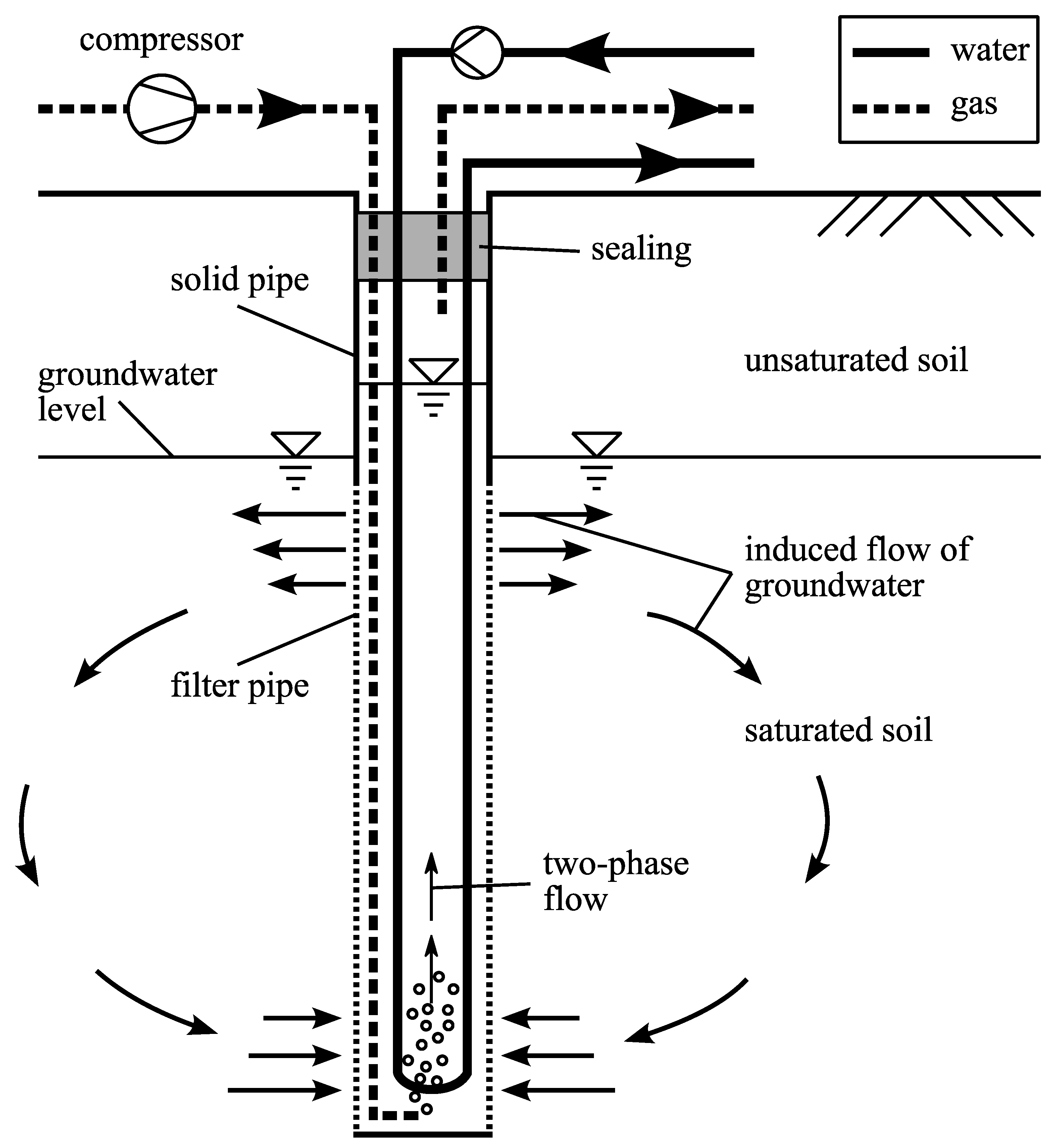
2.1.2. Geothermal Systems

As described above, two different geothermal systems can be utilized for the considered air conditioning system. Details about both geothermal systems are provided in the following.
Geothermal System 1.
Geothermal system 1 is located at the campus of Hamburg University of Technology in close proximity to the air conditioning system. It consists of one double U-tube BHX with a final drilling depth of 80 m below the ground surface. The soil primarily consists of sand with different grain sizes, up to a depth of 30 m. The soil is predominantly made of micaceous clay underneath. Further information about this geothermal system is provided by [3].
Geothermal System 2.
Geothermal system 2 consists of two BHXs, constructed as double U-tube heat exchangers with a final drilling depth of 29 m each. Due to the lack of space at the university campus, the BHXs are located approximately 15 km away from the air conditioning system. In real time, measurement data are exchanged via the internet between the air conditioning and the geothermal site to ensure reliable system operation.
The structure of the soil is equal for both BHXs. The first 2 m below the ground surface is made of a mixture of artificial infill with demolition waste and native soil. From 2 m to 3.5 m below the ground surface, the soil consists of clay. Within a depth of 3.5 m to 11 m, there are fine sands (gray), and between 11 m and 30 m, there are medium sands (gray). Additionally, the water table lies at approximately 2 m below ground level, but no significant natural groundwater flows are present. A grouting material with a thermal conductivity of 2 W K−1 m−1 is used. At a distance of 5 m, the GI-BHX, shown in Figure 3, is placed. Over the full length of the groundwater layer, a filter pipe is used. For direct connection between the well and surrounding soil filter, gravel is used instead of grouting material. At the lowest point inside the well, gas (nitrogen) is injected through an additional pipe. As a result, a pressure difference, with a lower pressure at the bottom and higher pressure at the top, is induced inside the well [12]. Due to the pressure difference compared with the surrounding soil (bottom: lower pressure; top: higher pressure), an artificial, circulating groundwater flow emerges. Inside the well, the two-phase flow (a mixture of water and gas) rises, and gas is discharged through the sealing to the environment. By inducing a water flow, the heat transfer inside the well is increased, and a larger volume of the surrounding soil is thermally activated. Therefore, gas injection borehole heat exchangers are promising in terms of reducing drilling depth and/or reducing the number of borehole heat exchangers without limiting the thermal capacity of the geothermal system.

2.1.3. System Control

The air conditioning system is designed to keep indoor room air conditions within thermal comfort limits of category I according to the German standard DIN EN 15251 [14] with the minimum possible power consumption of the entire system. To achieve that, the volume flows related to the geothermal system performance (summer: cooling coil, cooling ceiling; winter: reheating coil, heating ceiling) are added and fed by half to the BHX and the GI-BHX with respect to geothermal system 2. Inlet temperature and volume flow rate are controlled to be identical for both BHXs. For summer operation, previous studies showed that a BHX outlet temperature of less than 18 °C is required to achieve thermal comfort within the investigated air conditioning system [15]. During peak loads, the cooling power of the soil can be exceeded, and the resulting room temperature lies outside of the desired comfort range. Conventional BHXs are limited in their ability to increase cooling power, especially in terms of dynamic loads. In the current system configuration of geothermal system 2, a gas volume flow rate of V ˙ gas = 15   L   min 1 is injected in the GI-BHX as soon as the combined outlet temperature of the BHX and GI-BHX rises above 18 °C. Contrary to summer operation, high heating demands can occur during winter operation. To enhance the performance of the GCHP, the same gas volume flow rate of V ˙ gas = 15   L   min 1 is injected continuously in the GI-BHX when the GCHP is operated.

2.1.4. Performance Investigation of the Geothermal Systems

To monitor the system’s performance, several sensors are used at each site. Table 1 gives an overview of relevant measurement devices and corresponding measurement uncertainties for evaluating the performance of the geothermal systems and the GCHP. The resulting measurement uncertainties are calculated according to GUM [16]. In the case of the GCHP, the coefficient of performance ( COP GHCP ) is used as a performance indicator. It is defined as shown in Equation (1).
COP GHCP = Q ˙ cond P el
In addition to the electric power consumption of the heat pump, P el includes all auxiliary pumps needed to operate the heat pump. The heat flow rate for all heat exchangers is calculated as given in Equation (2).
Q ˙ = ρ · V ˙ · c p · ( ϑ out     ϑ in )

2.2. Measurement Results

Experimental results presented in this section are based on measurement data from heating and cooling periods in 2019. Differences in the performance of BHX and GI-BHX are highlighted. The test facility is operated every day from 7 a.m. to 10 p.m., and measurement data are logged every minute. The system evaluation is divided into summer and winter operations. Unless otherwise stated, the following system evaluation relies on system operation using geothermal system 2.

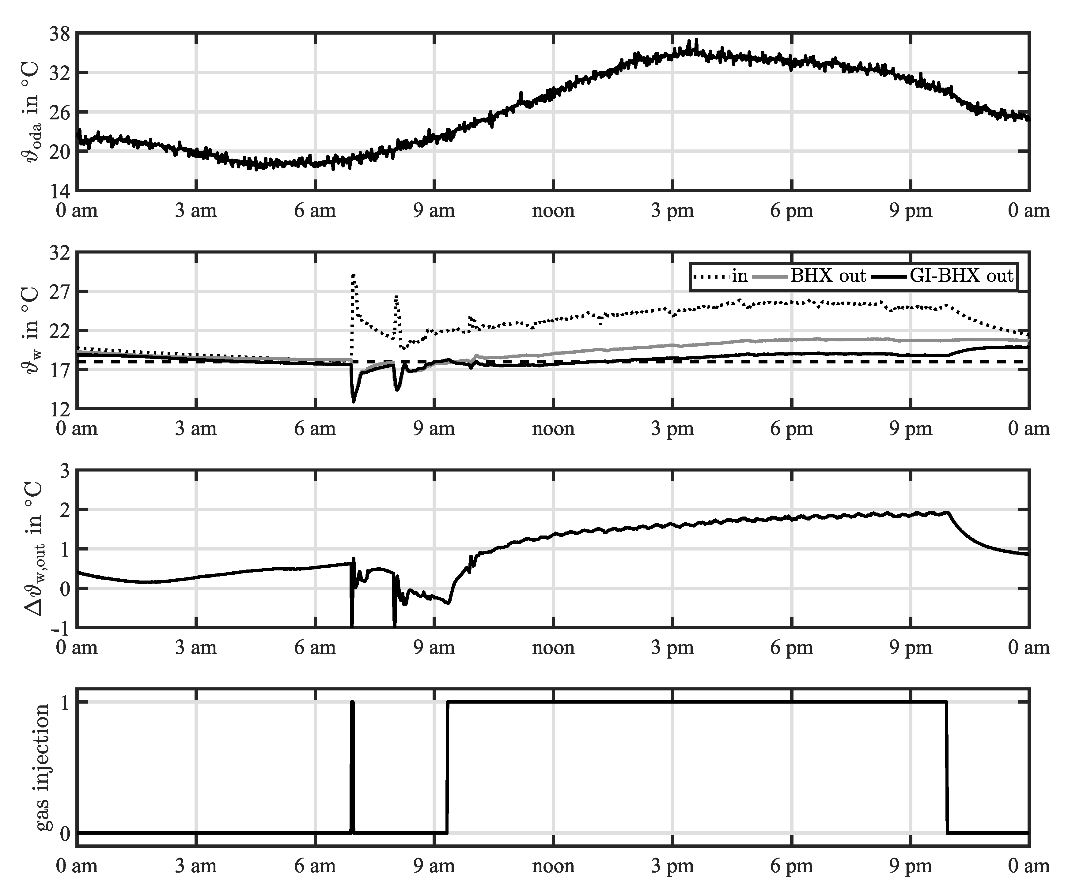
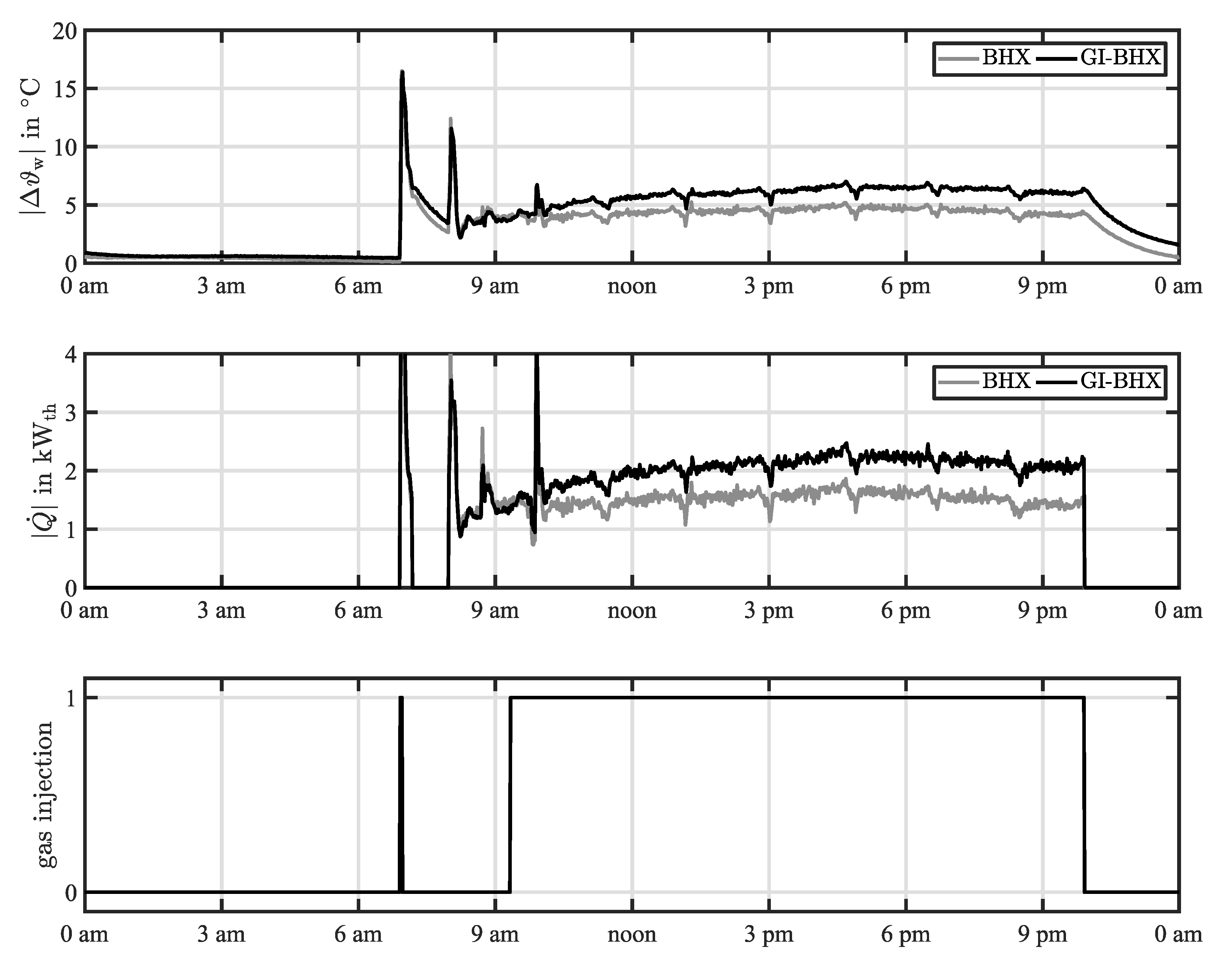
2.2.1. Summer Operation

Due to the lack of sufficient regeneration time, the cooling power of the soil can be exceeded during hot periods in the summer. As a result, the outlet temperature of the BHX rises above the required temperature level of 18 °C. In Figure 4, a typical temperature profile of one day is shown regarding the inlet and outlet temperatures of the geothermal system during a hot period in the summer with outside air temperatures of up to ϑ oda = 35 ° C . The temperature level of 18 °C is shown with a black dashed line in Figure 4 (upper center).
It can be seen that the inlet temperature slightly increases from the startup of the air conditioning system at 7 a.m. until approximately 5 p.m. Temperature peaks at the beginning of system operation (approx. 7 a.m. and 8 a.m.) are related to startup procedures of the system and the cooling circuits. Shortly after 9 a.m., a combined outlet temperature of 18 °C of the BHX and the GI-BHX in geothermal system 2 is achieved. Therefore, gas injection is started and the outlet temperature of the GI-BHX slightly decreases. After the initial decrease in outlet temperature, the GI-BHX is able to keep the outlet temperature nearly constant at 19 °C despite increasing inlet temperatures, whereas the outlet temperature of the conventional BHX further increases. Thus, the difference in outlet temperature between the two BHXs continuously increases during the day with a maximum temperature difference of Δ ϑ w , out 2 ° C at the end of the operation time, as shown in Figure 4 (lower center). The resulting heat flow rates over each BHX are shown in Figure 5.
From Figure 5, it can be seen that the cooling power of the GI-BHX increases directly when the gas injection is started. Afterward, the cooling power of the GI-BHX keeps rising due to the increasing inlet temperature. For the conventional BHX, the cooling power is nearly constant throughout the whole day. The maximum cooling power at a steady state is ( 2.3 ± 0.14 ) kW th for the GI-BHX and ( 1.7 ± 0.12 ) kW th for the BHX, respectively. The difference in the progression of cooling power due to gas injection shows the ability of the GI-BHX to act as a fast and dynamic control tool. As a result, integrating several GI-BHXs in large geothermal systems of conventional BHXs can be beneficial. By making use of the gas injection, a sufficient amount of additional cooling power is available as a backup to cover peak load cooling demands. Thus, the overall number of BHXs can be reduced, and it is not necessary to oversize the system.

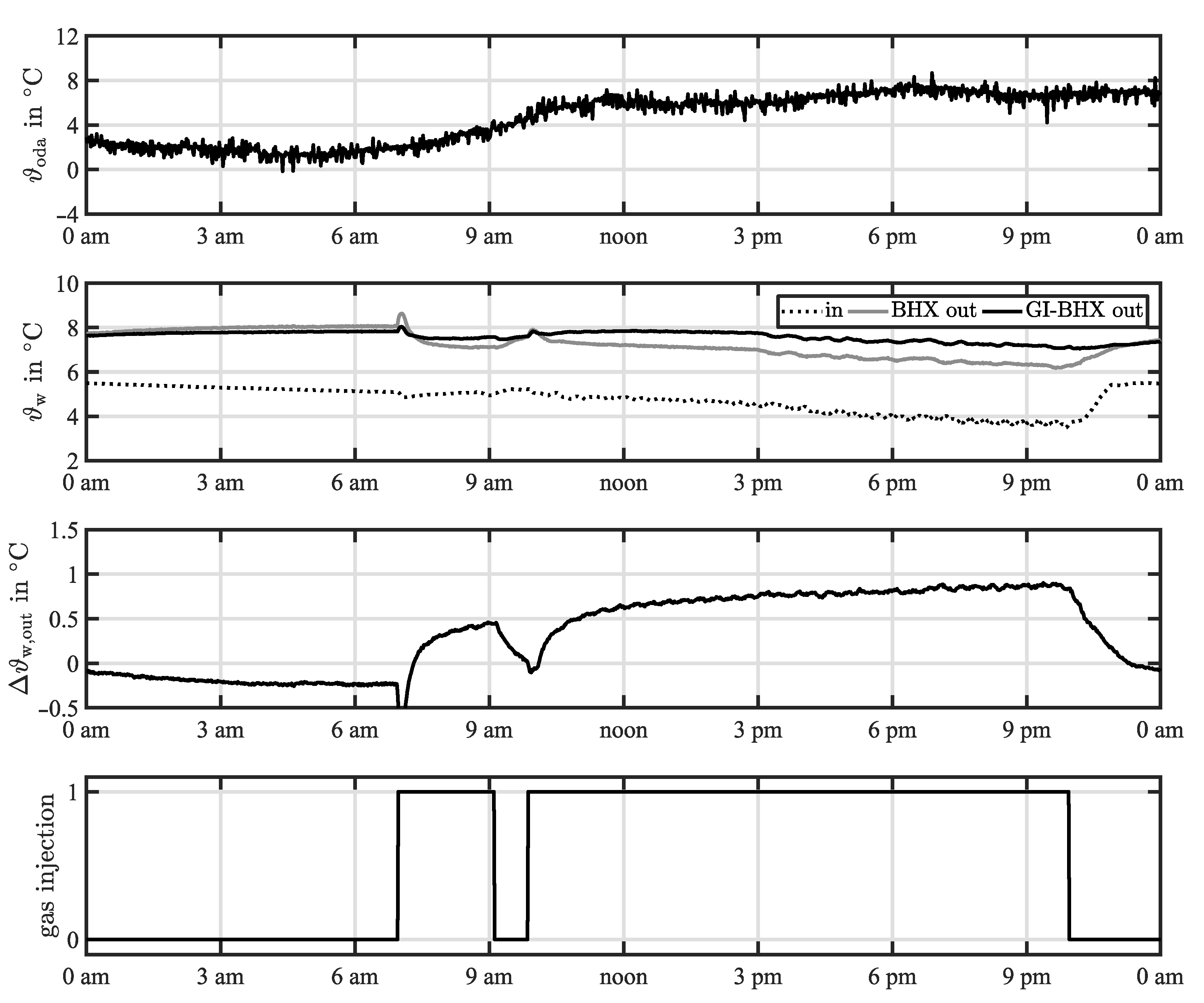
2.2.2. Winter Operation

During wintertime, the soil is used as a heat source for a GCHP system in terms of heating applications. Contrary to summer operation, higher outlet temperature levels of the geothermal system are favored in winter to operate the GCHP efficiently. In Figure 6, the inlet and outlet temperatures of geothermal system 2 are shown. Due to moderate outside air conditions with outside air temperatures above 5 °C during the day, GCHP operation was not required between 9 a.m. and 10 a.m. For the remaining operation time, the GCHP system was operated at the lowest power level, resulting in limited influences on the soil. It can be seen that the outlet temperature of the GI-BHX is nearly constant during operation despite decreasing inlet temperature. In the case of the conventional BHX, the outlet temperature decreases according to the inlet temperature. Due to these profiles, the BHX outlet temperature difference increases during the time of operation. The profile of Δ ϑ w , out is similar to the equivalent temperature profile during summer but on a lower temperature level. The maximum BHX outlet temperature difference of Δ ϑ w , out 0.9 ° C is achieved at the operation time for the considered period.
The resulting temperature differences across each BHX and thermal power outputs are shown in Figure 7. Due to the nature of the geothermal system, the temperature difference across the BHX increases during operation. The slope of increasing temperature difference is higher with the GI-BHX compared to the conventional BHX. As a result, the same effect can be seen for the heating power of the geothermal system. This is an effect of the increased thermal capacity of the soil due to the injection of gas, therefore thermally activating a larger volume of the soil. Thus, the thermal performance of the geothermal system is enhanced. In this case, the thermal power increase for the GI-BHX is limited to around 0.2   kW th at a steady state compared with the conventional BHX. With respect to the related measurement uncertainties, the validity of the comparison is limited. Fluctuations of thermal power output are caused by the control strategy of the overall system.
Regarding the performance of the GCHP, the utilization of the soil as a heat source can reduce the overall soil temperature level around the BHX during system operation. As a result, under similar ancillary conditions and reduced soil temperature, the heat flux of the soil declines. Hence, the COP of the GCHP also decreases. To further evaluate the effect of a gas injection borehole heat exchanger on GCHP performance, the dependence of COP GCHP on GCHP temperature lift ( Δ ϑ GCHP = ϑ w , out , cond     ϑ w , out , BHX ) is considered. To evaluate the performance differences, the two different geothermal system configurations, as shown in Figure 2, are compared. Therefore, the air conditioning system was operated with geothermal system 1. Using real-time data exchange with geothermal system 2, the BHX inlet temperature, as well as the overall volume flow rate, was controlled to be identical for both geothermal systems. A characteristic diagram showing the dependence of COP GCHP on the GCHP temperature lift was set up based on stationary operation states of the GCHP system in combination with geothermal system 1 in previous studies. Figure 8 shows the resulting dependence between the COP and the temperature lift in partial load (60%) and full load (100%). Despite the combined lower drilling depth of geothermal system 2 compared with geothermal system 1, the performance of both GCHP systems is within the same range. Nevertheless, the conventional BHX of geothermal system 2 still limits the capacity of the overall geothermal system when using the combined outlet temperature of both BHXs supplied to the GCHP system. Generally, GCHP performance decreases with increasing temperature lift Δ ϑ GCHP across the GCHP system. This dependence appears stronger at partial load but at the same time appears at a higher level of COP GCHP .

3. Conclusions

The presented experimental study shows a possible way to improve peak load handling in desiccant assisted air conditioning systems relying on geothermal systems as a heat source and heat sink. The main results can be summarized as follows.
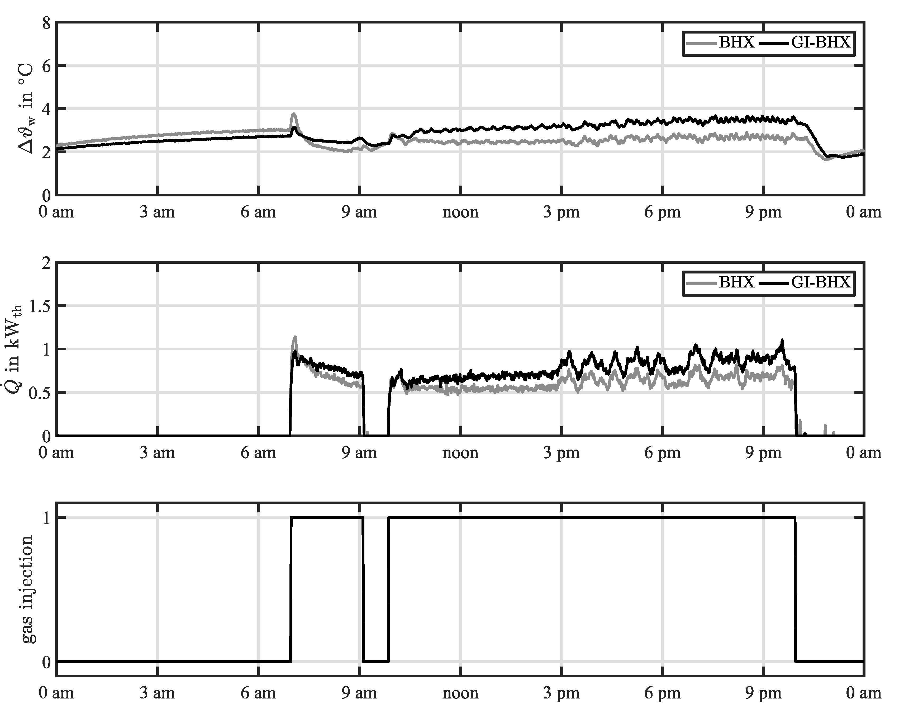
  • During hot or cold periods, the cooling or heating power of the soil, respectively, can be limited due to short regeneration periods. The induced ground water flow of the GI-BHX can improve heating and cooling loads during summer and winter operation.
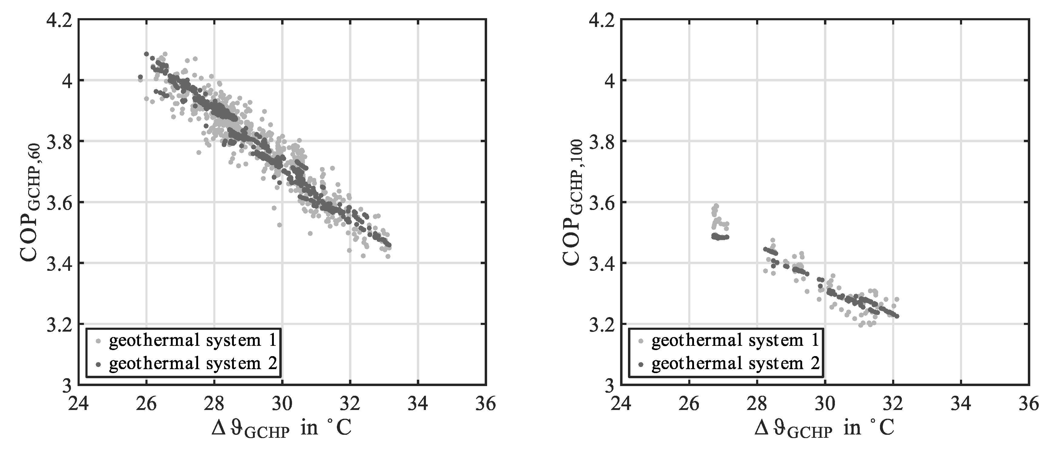
  • Gas injection can be used as an additional control mechanism during peak loads. During summer operation, 600   W th of additional cooling power can be achieved compared with a conventional BHX. For heating purposes in combination with a GCHP, the power increase using a GI-BHX was limited to 200   W th with no positive effect on the performance of the GCHP. This makes it possible to avoid a backup system or to avoid oversizing the geothermal system.
  • BHX gas injection can be promising in terms of reducing the size of a geothermal system without constraints in thermal capacity. Therefore, using several GI-BHXs within a larger geothermal field could offer reliable peak load handling.
  • In terms of further system evaluations, other operation strategies for the GI-BHX will be considered. At present, a detailed economic and energetic analysis, including the expenses of the GI-BHX, is being carried out and will be published in future research work.

Author Contributions

Conceptualization, F.R., P.N. and M.S.; methodology, F.R., P.N. and M.S.; software, F.R.; validation, F.R., P.N. and M.S.; formal analysis, F.R. and P.N.; investigation, F.R. and P.N.; writing—original draft preparation, F.R.; writing—review and editing, F.R.; visualization, F.R. and P.N.; supervision, F.R., P.N. and M.S.; project administration, F.R., M.S., J.G. and G.S.; funding acquisition, J.G. and G.S. All authors have read and agreed to the published version of the manuscript.

Funding

This work is being conducted in the frame of a project funded by the Federal Ministry for Economic Affairs and Energy (www.bmwi.de (accessed date 9 February 2021)), cf. project funding reference number 03ET1421A.

Conflicts of Interest

The authors declare no conflict of interest.

Nomenclature

Symbols
A area, m2
c p specific heat capacity, J kg−1 K−1
COP Coefficient of Performance, dimensionless value
EER Energy Efficiency Ratio, dimensionless value
P electrical power, W
Q ˙ heat flow rate, W
V ˙ volume flow rate, m3 s−1
Δ difference, dimensionless value
ϑ temperature, °C
ρ density, kg m−3
Subscripts and Abbreviations
BHXborehole heat exchanger
condcondenser
elelectrical
etaextract air
exaexhaust air
GCHPground-coupled heat pump
GI-BHXgas injection borehole heat exchanger
ininlet
nomnominal
odaoutside air
outoutlet
STUsolar thermal unit
supsupply air
ththermal
wwater

References

  1. International Energy Agency. The Future of Cooling; OECD/IEA: Paris, France, 2018.
  2. Casas, W.; Schmitz, G. Experiences with a gas driven, desiccant assisted air conditioning system with geothermal energy for an office building. Energy Build. 2005, 37, 493–501. [Google Scholar] [CrossRef]
  3. Niemann, P.; Schmitz, G. Experimental Investigation of a Ground-Coupled Air Conditioning System with Desiccant Assisted Enthalpy Recovery during Winter Mode. Appl. Therm. Eng. 2019, 160, 114017. [Google Scholar] [CrossRef]
  4. Speerforck, A.; Schmitz, G. Experimental investigation of a ground-coupled desiccant assisted air conditioning system. Appl. Energy 2016, 181, 575–585. [Google Scholar] [CrossRef] [Green Version]
  5. Gonçalves, P.; Angrisani, G.; Sasso, M.; Gapsar, A.R.; Gameiro da Silva, M. Exergetic analysis of a desiccant cooling system: Searching for performance improvement opportunities. Int. J. Energy Res. 2013, 38, 714–727. [Google Scholar] [CrossRef]
  6. Cui, Y.; Zhu, J.; Twaha, S.; Riffat, S. A comprehensive review on 2D and 3D models of vertical ground heat exchangers. Renew. Sustain. Energy Rev. 2018, 94, 84–114. [Google Scholar] [CrossRef]
  7. El-Agouz, S.A.; Kabeel, A.E. Performance of desiccant air conditioning system with geothermal energy under different climatic conditions. Energy Convers. Manag. 2014, 88, 464–475. [Google Scholar] [CrossRef]
  8. Naicker, S.S.; Rees, S.J. Performance analysis of a large geothermal heating and cooling system. Renew. Energy 2018, 122, 429–442. [Google Scholar] [CrossRef] [Green Version]
  9. Luo, J.; Rohn, J.; Bayer, M.; Priess, A.; Wilkmann, L.; Xiang, W. Heating and cooling performance analysis of a ground source heat pump system in Southern Germany. Geothermics 2015, 53, 57–66. [Google Scholar] [CrossRef]
  10. Eicker, U.; Vorschulze, C. Potential of geothermal heat exchangers for office building climatization. Renew. Energy 2009, 34, 1126–1133. [Google Scholar] [CrossRef]
  11. Kurevija, T.; Kalantar, A.; Macenić, M.; Hranić, J. Investigation of Steady-State Heat Extraction Rates for Different Borehole Heat Exchanger Configurations from the Aspect of Implementation of New TurboCollectorTM Pipe System Design. Energies 2019, 12, 1504. [Google Scholar] [CrossRef] [Green Version]
  12. Luber, M.; Brauns, J. Luftinjektionsbrunnen zur In-situ-Grundwassersanierung—Großmaßstäbliche Sanierungsversuche in der VEGAS. Grundwasser 2003, 8, 81–90. [Google Scholar] [CrossRef]
  13. Ma, X.; Grabe, J. Efficiency Increase of Soil Heat Exchangers due to Groundwater Flow and Air Injection Wells. In Proceedings of the World Geothermal Congress, Bali, Indonesia, 25–30 April 2010. [Google Scholar]
  14. DIN EN 15251: Indoor Environmental Input for Design and Assessment of Energy Performance of Buildings Addressing Indoor Air Quality, Thermal Environment, Lighting and Acoustics, 12-2012 ed.; Beuth Verlag GmbH: Berlin, Germany, 2012.
  15. Speerforck, A. Investigation of a Desiccant Assisted Geothermal Air Conditioning System. Ph.D. Thesis, Verlag Dr. Hut, Munich, Germany, 2019. [Google Scholar]
  16. Joint Committee for Guides in Metrology: Evaluation of Measurement Data—Guide to the Expression of Uncertainty in Measurement; Version JCGM 100:2008; Bureau International des Poids et Mesure: Saint Cloud, France, 2008.
Figure 1. Test facility (a), air handling unit (b) and ground-coupled heat pump (c).
Energies 14 00926 g001
Figure 2. System layout of the test facility and the geothermal systems.
Energies 14 00926 g002
Figure 3. Layout and operating principle of the gas injection geothermal heat exchanger (GI-BHX) (according to [13]).
Energies 14 00926 g003
Figure 4. Profiles of outside air temperature (top), geothermal system inlet and outlet temperatures (upper center), outlet temperature difference between BHX and GI-BHX (lower center) and times of gas injection (bottom) during the course of one day during summer operation.
Energies 14 00926 g004
Figure 5. Profiles of the temperature difference across each BHX (top), resulting heat flow rates (center) and times of gas injection (bottom) during the course of one day in summer operation.
Energies 14 00926 g005
Figure 6. Profiles of outside air temperature (top), geothermal system inlet and outlet temperatures (upper center), outlet temperature difference between BHX and GI-BHX (lower center) and times of gas injection (bottom) during the course of one day in winter operation.
Energies 14 00926 g006
Figure 7. Profiles of temperature difference across each BHX (top), resulting heating load (center) and times of gas injection (bottom) during the course of one day in winter operation.
Energies 14 00926 g007
Figure 8. Comparison of the coefficient of performance (COP) of the GCHP at 60% (left) and 100% (right) compressor power level.
Energies 14 00926 g008
Table 1. Measurement devices and corresponding measurement uncertainties.
Measured Value Sensor Type/Measuring PrincipleMeasurement Uncertainty
Water temperature at
air conditioning site
ϑ Pt100
(accuracy class W0.1)
±1/3·(0.3 + 0.005·ϑ) °C
Volume flow (water) at
air conditioning site
V ˙ Electromagnetic
flow meter
measured flow velocity:
±0.5% of reading ± 1 mm s−1
Electric power at air
conditioning site
P AC energy meter±2% of reading
Water temperature at
geothermal site
ϑ Pt1000
(accuracy class W0.1)
±1/3·(0.3 + 0.005·ϑ) °C
Volume flow (water) at
geothermal site
V ˙ Electromagnetic
flow meter
measured flow velocity:
±0.5% of reading ± 2 mm s−1
Publisher’s Note: MDPI stays neutral with regard to jurisdictional claims in published maps and institutional affiliations.

