Article

Strength Tests of Hardened Cement Slurries for Energy Piles, with the Addition of Graphite and Graphene, in Terms of Increasing the Heat Transfer Efficiency

Laboratory of Geoenergetics, AGH University of Science and Technology in Krakow, al. Adama Mickiewicza 30, 30-059 Krakow, Poland
*
Author to whom correspondence should be addressed.
Energies 2021, 14(4), 1190; https://doi.org/10.3390/en14041190
Submission received: 3 December 2020 / Revised: 14 February 2021 / Accepted: 16 February 2021 / Published: 23 February 2021
(This article belongs to the Special Issue Advancements in Thermal and Energy Geotechnics)

Abstract

:
The development of civilization, and subsequent increase in the number of new buildings, poses engineering problems which are progressively more difficult to solve, especially in the field of geotechnics and geoengineering. When designing new facilities, particular attention should be paid to environmental aspects, and thus any new facility should be a passive building, fully self-sufficient in energy. The use of load-bearing energy piles could be a solution. This article presents research on the cement slurry formulas with the addition of graphite and graphene, that can be used as a material for load-bearing piles. The proposed solution is to introduce U-tubes into the pile to exchange heat with the rock mass (the so-called energy piles). A comparison of four slurry formulas is presented: the first one consisting mainly of cement (CEM I), graphite, and water, and the remaining three with different percentages of graphene relative to the weight of dry cement. The results could contribute to the industrial application of those formulas in the future.

1. Introduction

In urban areas, there are often many locations with geotechnical properties excluding them from construction. These can be, for example, old landfills, coastal regions, wetlands, or heaps [1]. Such plots may become attractive to investors after strengthening the ground with modern geoengineering methods, e.g., using piling and micropiling (Figure 1).
Power engineering is also an important developing and changing sector of the economy. It includes renewable energy sources, along with shallow geothermal energy, described multiple times in the past [2,3,4,5,6]. Shallow geothermal energy is extracted by geothermal heat pumps with borehole heat exchangers. These types of installations enable one to obtain low-temperature heat from the rock mass in winter, and in summer “collecting cold” from the rock mass cooled in winter for air conditioning [7]. The air conditioning process based on the rock mass simultaneously regenerates heat resources in the rock mass. More frequent use of geothermal energy systems (Figure 2) is in line with the care for the natural environment and the departure from conventional heat sources. Geothermal solutions make it possible to provide buildings with domestic hot water, interior heating, and air conditioning while reducing the emission of pollutants into the atmosphere. There are many concepts of borehole heat exchangers described in the literature [8]. One of the interesting ideas is the use of exploited wells [9], e.g., oil and gas, as deep borehole heat exchangers [10,11].
Geothermal heat pumps (GHPs) or ground source heat pumps (GSHPs) are reversible. In winter, low-temperature heat from the Borehole Heat Exchangers BHEs is supplied to the evaporator, and the condenser feeds the heating system. The opposite occurs in summer: the heat collected by the evaporator connected to the air conditioning system of the building is given off to the rock mass by the BHEs connected to the condenser. In such a system, the rock mass acts as a buffer, storing both heat and cold. In summer, it is heated by solar heat received from the building interior during air conditioning. In winter, the heated rock mass transfers the heat to the heating system and cools down. The following summer, the cooled rock mass is the source of cooling for the air conditioning. The heat from the air conditioning therefore regenerates the heat resources obtained from the rock mass in winter [12]. This way, more favorable operating parameters of the heat pump (coefficient of performance, COP) are obtained. As a result, GSHPs have higher COPs than air source heat pumps.
Therefore, an interesting solution is to combine ground strengthening through piling, together with the possibility of obtaining heat from the rock mass [14]. Energy piles are the technology that combine special foundations (foundation piles) and a system of borehole heat exchangers. Such installations may turn out to be a very good solution in case of unused areas characterized by unfavorable geotechnical conditions and have several advantages resulting from the use of an environmentally friendly source of heat (heat/cold storage). This technology is already successfully used in the world, i.e., to reduce the cost of the independent construction of load-bearing piles and BHEs.
The indispensable factor for the possibility of using the above-mentioned technology is the necessity to meet all strength requirements generated by the loads of the designed structure. At the same time, it is advantageous to use cement slurry which has an increased thermal conductivity after setting. This enables heat exchange between the heat carrier and the rock mass with an increased heat flux (heating power [15]).
This article presents the research on the mechanical strength of hardened cement slurries with the addition of graphite and graphene. The use of these additives causes an increase in the thermal conductivity of the concrete. The compressive and bending strength evaluation of hardened cement slurry samples with the addition of graphite and graphene determines the suitability of such additives for use in energy piles.

2. Energy Piles

The term foundation should be understood as the lowest part of the structure in direct contact with the ground, to which it safely transfers its own weight and all its loads [16]. A foundation (load-bearing) pile is an element of a special foundation, which is used to transfer the external loads generated by the structure from weak layers of soil or water to deeper formations with greater load-bearing capacity in order to secure the foundation of the structure [17].
An energy pile is defined as a foundation pile containing in its structure a system similar to that installed in a borehole heat exchanger [18]. The heat exchanger installed inside the load-bearing pile is designed to exchange the heat of the rock mass through the liquid circulating inside it (heat carrier). A circulating pump operation transports the carrier to the GSHP located inside the facility. Heat exchanger tubes in BHEs are usually made of polyethylene [9].
Year after year, an increasing number of buildings are constructed on pile foundations, which are one of the latest methods of special foundation [9]. In the face of rising conventional energy prices and the side effects associated with its production, the technology of combining foundation piles with BHEs is increasingly used in highly developed countries. When creating a borehole for a load-bearing pile and its reinforcement, it is possible to run a certain number of U-tubes into the hole, which in the future can be used as a special type of borehole heat exchanger [19]. Ideas for using a foundation to extract heat or cold from a rock mass appeared in Switzerland in around 1990, in Austria in the 1980s [20,21], and later in other European countries [22,23,24,25,26,27]. One of the first experiments took place in Germany [20].
The right material for making load-bearing piles is an important issue [28]. Such a material should be characterized by suitable strength values to meet the appropriate conditions for a structure to be built on piles [29,30]. Details on the materials for energy piles are extensively discussed in Sani et al. [31]. A pile can transfer loads both through its base and through the side surface. The distribution of the generated forces over these two pile surfaces depends mainly on its length and diameter, as well as the thickness and properties of geological layers intersected by the load-bearing pile [17]. When merging the foundation pile with the heat exchanger in the form of U-tubes, in addition to the strength properties, attention should be paid to the properties related to heat conduction. In order to maximize the efficiency of borehole heat exchangers, special slurries are used to tightly fill the space between the pipes and the rock wall [32]. Such slurries should be characterized by the highest possible heat conductivity [33], since the hardened slurry is an intermediary in the heat flow from the rocks to the heat carrier circulating in the exchanger tubes or in the opposite direction [34].
The installation’s operating principle consists of the consumption of thermal energy from the ground and is relatively simple in the case of deep foundation technology. This system is analogous to the commonly applied method using GSHP with a low-temperature source in the form of a rock mass with BHEs [35]. The difference is in a much smaller depth in the ground, resulting in an efficiency reduction of a single exchanger [36].
In order to prevent cumulative energy losses, a large number of U-tubes are often made in the load-bearing pile. The lack of additional costs, apart from the necessity to equip piles with heat exchangers located on a steel skeleton, speaks in favor of the widespread use of this solution. The purposefulness of using the described technology is especially visible in buildings with large dimensions, requiring a solid foundation [37]. In addition, the energy piles system, apart from being used for heating purposes, can also work in reverse, supplying cold in summer. This can also be performed in a passive mode, i.e., without the use of a heat pump [38]. Such a solution is technically simple, additionally stimulating the energy and economic efficiency of the entire system. Aspects affecting the correct operation of energy piles (in terms of energy) and the efficiency of the system are, for example, the number of peak load hours per year, or the speed of groundwater flow.
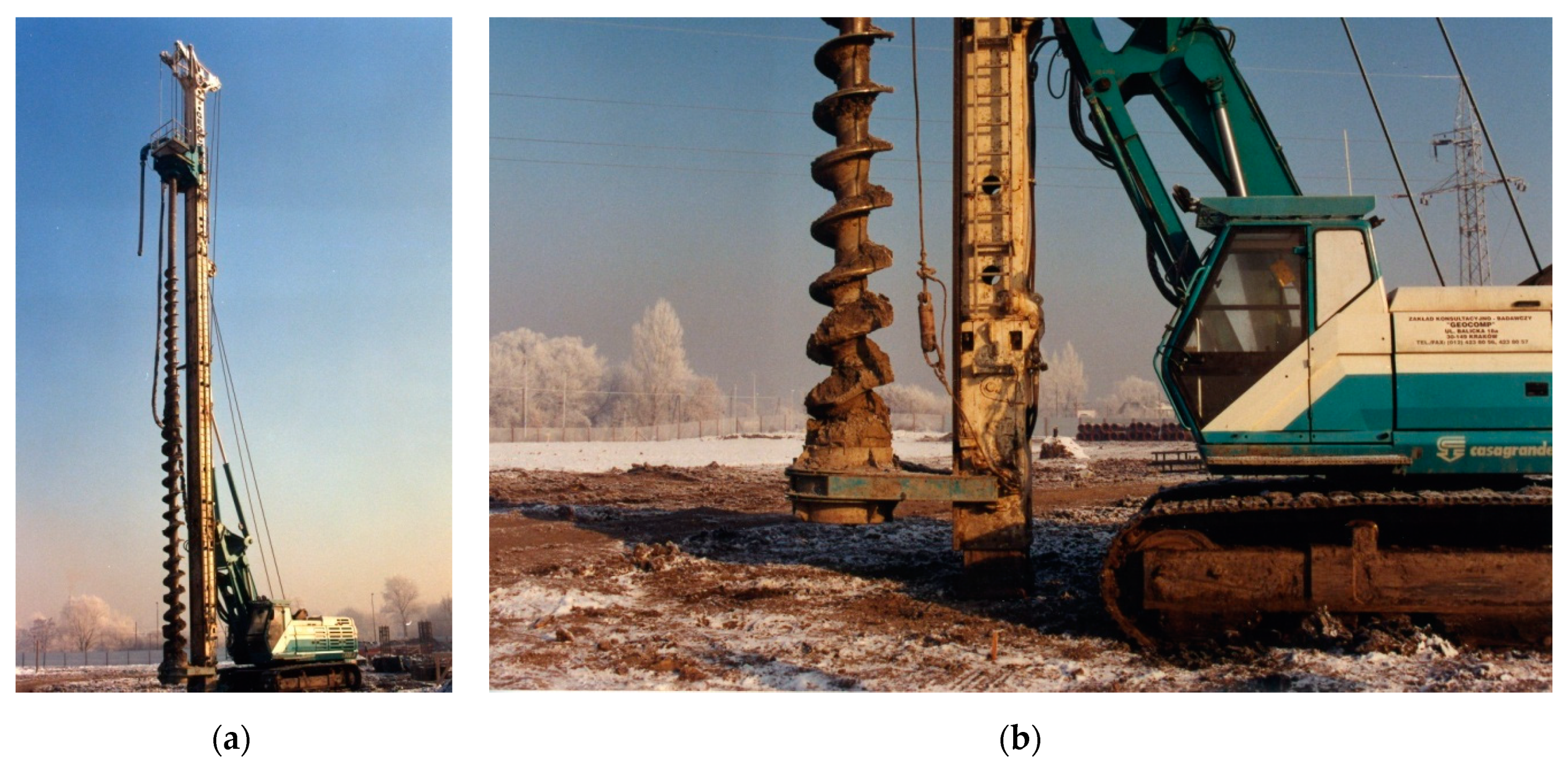
The execution of energy piles is directly related to the creation of load-bearing (foundation) piles due to some of the same functions they perform. For the implementation of investments based on energy piles, most commonly, piles are made in the boreholes created using the auger drilling method. Planned boreholes are made with the use of drill columns or poles (Figure 1). Depending on the conditions of a given project, the appropriate type of drill bit is selected. This method is characterized by not requiring drilling fluid (mud), so the holes are drilled dry. This is possible because the energy piles reach relatively shallow depths, where the rocks are loose. Lightweight mobile drilling rigs are usually used for creating boreholes using this method [18]. In Poland, pile boreholes are most often made with the use of CFA (continuous flight auger) technology, without piping. The drilling and cementing process takes place in two separate phases occurring directly one after another.
The most common design of the heat exchanger tubes in the energy pile is the U-tube installation [34]. However, there is the possibility to find innovative energy pile structures. One of them is a new concept of energy piles that uses phase change materials (PCM) in the form of enclosed tube containers [39]. What is new is a heat exchanger configuration, known as a deeply penetrating U-tube configuration, for energy piles. In this case, the heat exchange tube is embedded and attached to a reinforcement cage, with the tube being arranged in a U-shape and its bottom penetrating through the bottom of the pile and sticking deeply into the soil below the pile [40]. Information about double U-tubes, triple U-tubes and multi U-tubes installed in a steel pile foundation can be also found [41,42]. Additionally, in the literature there is information about spiral pipe configuration [43,44,45,46] or cone helix energy pile [47]. The heat transfer process of the buried spiral coils in piles is described, among others, by Cui [46]. In the mentioned source, a model of a transient heat source with a ring and a coil was described, and unambiguous analytical solutions in the field of temperature reaction were derived using the theory of Green’s function and the imaging method [46]. A new algorithm for spiral coil energy piles was also proposed by Go et al. [48]. It takes into consideration the influence of groundwater advection. Based on the results, after verifying the accuracy of the model, it can be concluded that the groundwater advection mitigates thermal interference between piles, as well as the long-term thermal resistance of the soil, which have an impact on the economical design of energy piles [48]. Spiral-shaped or helical tube heat exchangers have also been studied and both can be implemented in energy piles. According to the research on thermal performance of precast high-strength concrete energy piles containing W-ype (one spiral single U-pipe) and coil-type (helical) BHEs using numerical and experimental methods, Yoon et al. [49] observed that coil-type GHEs exhibit higher heat exchanging efficiency but poorer economic performance compared with the W-type BHE in the energy pile. Furthermore, Zarrella et al. [42] have shown that the helical pipes provide better thermal performance than the 3-U tube energy piles. Additionally, the pitch between the turns of the helix influences the peak load [50].
The required diameter of the energy pile containing the heat exchanger tubes is in the range from 0.4 m to 1 m, though larger sizes are created as well [
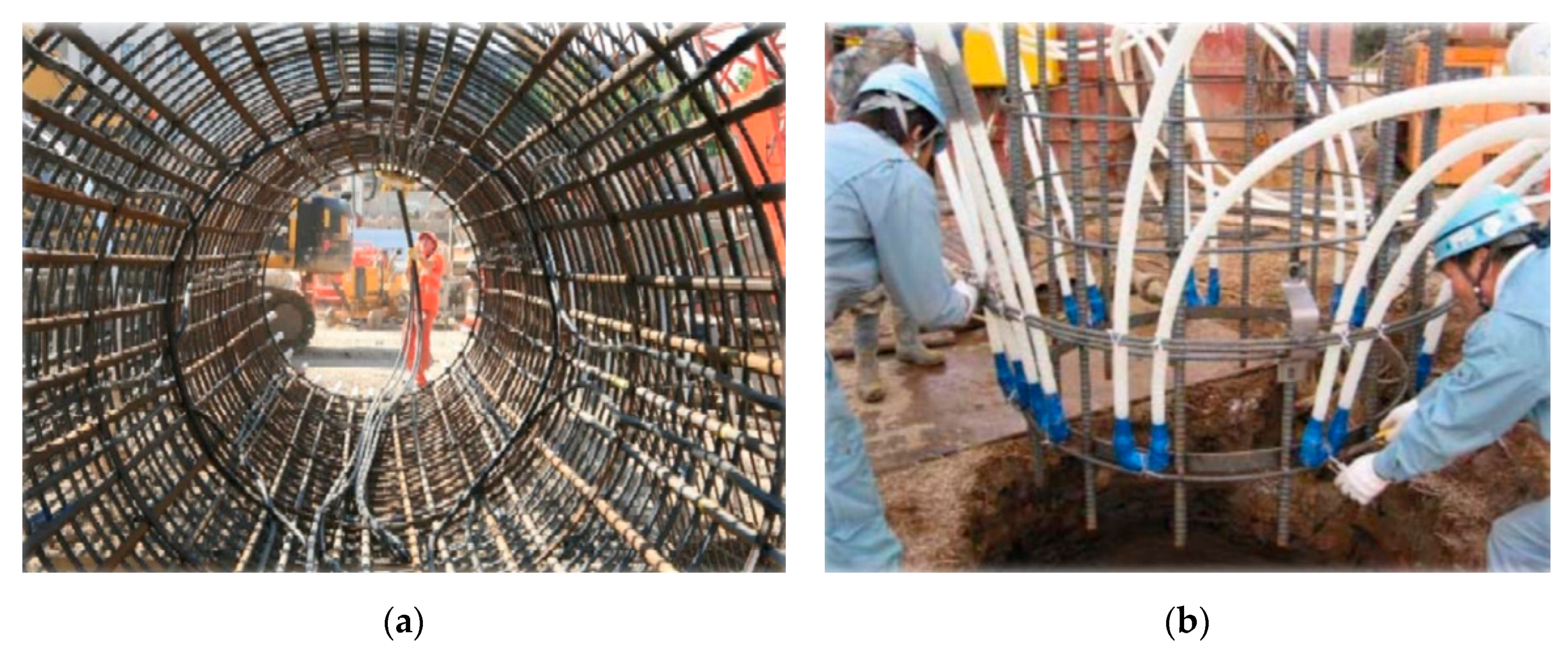
51]. The most common structures of reinforcement equipped with a system of heat exchanger pipes include elements in the form of a reinforcement cage (Figure 3, Figure 4 and Figure 5). In Krakow (Poland), steel profiles in the shape of an I-beam were used as a support structure for the exchanger tubes with a welded circular element (Figure 6), which ensured the minimum bend radius of the plastic pipes.
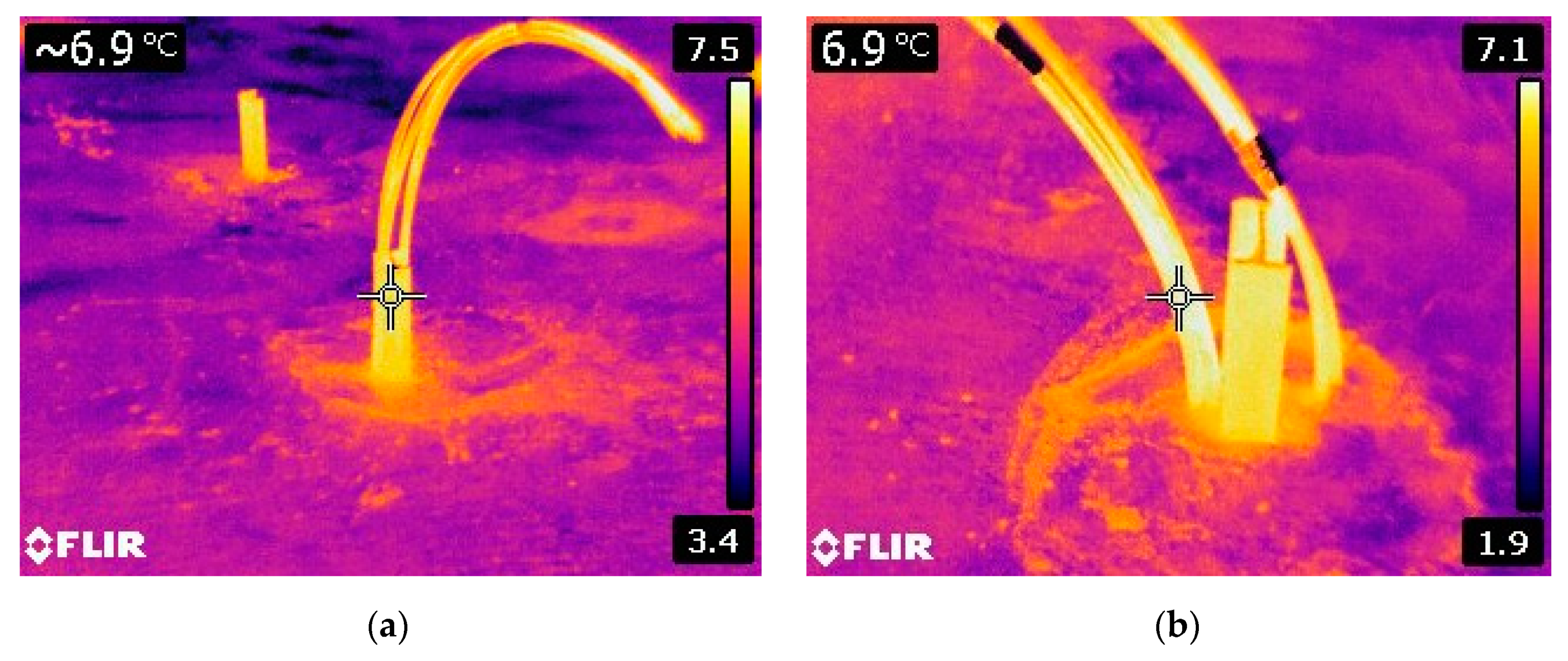
Figure 7 shows the constructed load-bearing energy piles for the building of the National Archives in Krakow. On the right, photos from the thermal imaging camera are presented, showing the thermal influence of the rock mass below the bearing plate. The heat conducted from the rock mass through the steel supporting structure for the heat exchanger tubes is manifested by an increased temperature relative to the surroundings. Figure 8 shows a close-up of the installed energy pile pipes. A temperature difference of several degrees Celsius is visible.
A single pile can deliver from 25 to 50 Wm−1 depending on its size, construction details, surrounding soil layers, and the system in which it operates [22,56]. The development of renewable energy sources, including energy piles, is in a way enforced by European law, because according to Directive 2010/31/EU of the European Parliament and of the Council of 19 May 2010, each new structure should be a nearly zero-energy building (from the end of 2020). New buildings occupied and owned by public authorities must be nearly zero-energy buildings [57,58]. Hence, the laboratory tests are carried out on the materials from which energy piles can be made and their thermal and mechanical properties [29], and numerous computer simulations are conducted to create appropriate computational models for forecasting the operation of piles and their design [58,59,60,61,62,63]. There are also frequent combinations of these two types of research, i.e., experimental research and computer analyses and simulations [64,65]. Numerous studies on computer simulations also take place in the field of typical borehole heat exchangers [66,67,68,69]. These analyses are often interrelated [70]. It is also recommended to perform the thermal response test (TRT) on the existing energy pile [71]. Currently, TRTs are commonly performed on borehole heat exchangers [1,72,73,74,75]. The TRT is a method of assessing the actual thermal properties of a rock mass in-situ [9,19,76]. The essence of the method is to measure the temperature changes of the heat carrier during its circulation in a closed cycle with the supply or thermal energy collection with constant heating power. In the case of a surface system, it must be ensured that the temperature measurements are not affected by the weather conditions. Much research has been conducted on the subject of thermal properties of energy piles [77,78,79,80]. Often, these data are also obtained using the thermal response test. However, the method of approach to research and their interpretation is generally different than in case of the classic TRT test performed on the borehole heat exchanger. Data from the TRT are often used to calibrate numerical models [60]. The possibility of using the TRT technique for large diameter energy piles was examined by Jensen-Page et al. [77]. Analytical models were tested against both the field data and further numerically generated synthetic TRT data. They concluded that it is necessary to consider the borehole length test and laboratory assessment of the thermal properties of concrete, both of which may add uncertainty to the results obtained. There are also other works on similar topics [79,81]. Franco et al. [79] have described the numerical sensitivity analysis of TRT in energy piles. They presented simulations taking into account different pile geometries and material properties, as well as estimation of errors introduced by a line heat source model to analyze the TRT results. Unfortunately, to evaluate the ground thermal response to their presence it is not possible to use classical analytical solutions due to their low aspect ratio and to the relevant effect of the heat capacity of the inner cylindrical volume as proven by Fossa et al [81]. Their work proposes a semi-analytical method of modeling ground heat exchangers with high flexibility in terms of their shape. This method is named multiple point sources (MPS) and involves the spatial superposition of an analytical solution for a single point source.

3. Preparation and Conduct of Research

To prepare the assumed cement recipes, CEM I 42.5R Portland cement was used. It is characterized by high early strength, high strength after 28 days, as well as a rapid increase in strength. This cement has stable quality parameters and low shrinkage [82].
The first of the additives used was graphite [83]. Its use in the right amount assumed the effect of increasing the thermal conductivity while improving the mechanical parameters. Flake graphite was used, which is a type of natural graphite. It has a metallic sheen and a highly ordered crystal structure [7]. The second additive in the formulas developed was graphene. Due to the variety of graphene products available on the market, the research focused on the addition of graphene in the form of a nanopowder with an average flake size of 12 nm.
Based on the past strength tests of samples (described in our previous article [7]). with the addition of graphite, the highest value was found for samples with 20% by the weight of cement (BWOC) addition of graphite at the water–cement ratio w/c = 1.0. The recipe had a positive effect on the thermal conductivity of the hardened cement slurry [7]. On this basis, it was decided to add a variable percentage of graphene admixture in the form of a nanopowder to the composition. The mere addition of graphene did not allow to obtain recipes with rheological, flow, and filtration parameters within the applicability limits. Hence, it was decided to use an agent: PSP-042 slurry liquefier. The final composition of the recipes is presented in Table 1.
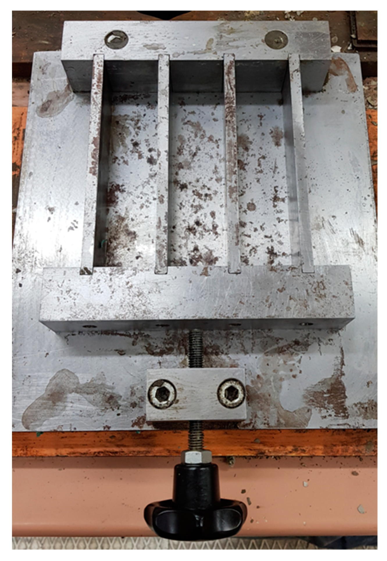
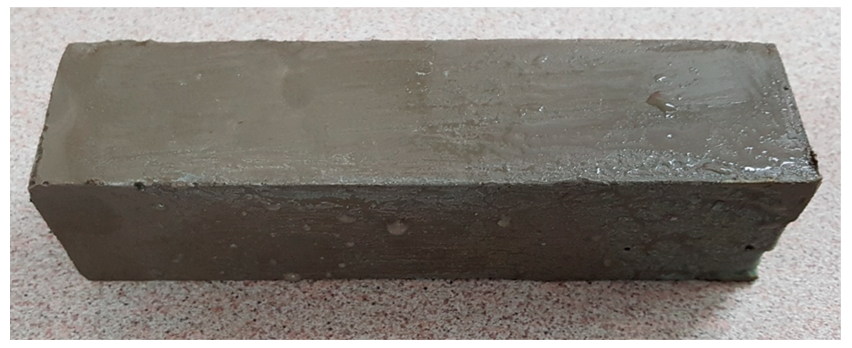
The samples were prepared in beam-shaped molds (Figure 9 and Figure 10) with dimensions of 40 × 40 × 160 mm. After setting, the samples were removed from the molds, properly labeled and placed in a water bath at approximately 20°C for 28 days.
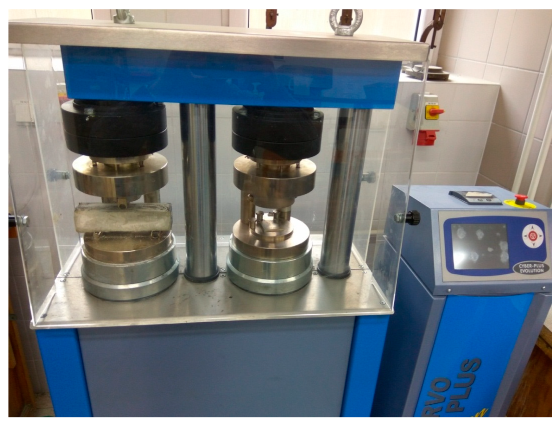
The bending and compressive strengths were measured using the Servo-Plus Evolution E183 hydraulic press (Figure 11). The press used in the research includes two measuring chambers equipped with separate pistons, with two independent measuring ranges. In principle, this device is used to measure the bending and compression strength of standard-sized beams. It enables the change of parameters in relation to the dimensions of the tested sample, so that the calculated value of the strength is as real as possible. It is related to frequent shrinkage or swelling of the hardening grout in the mold during the setting process. The measurement result displayed on the electronic panel of the device with a three-decimal place accuracy may contain a slight error (±0.5%). Scientific and technical research used to adopt the significance level as α = 5%, therefore Figure 12 shows the errors in strength measurements with such a risk of deviation. The value of the force with which the piston pressed on the sample at the moment of its breakage is registered by the device. Then, taking into account the exact dimensions of the tested beam and the surface on which the piston acted, the device records the stress values that occurred during fracture or compression.
The samples described above were prepared in accordance with PN-EN ISO 10426-2 “Cements and materials for well cementing, Part 2: Testing of well cements”, PN-85-G-02320 “Cements and cement pastes for cementing of boreholes”, PN-EN 196-1: 2016-07, and API SPEC 10A [84,85,86].
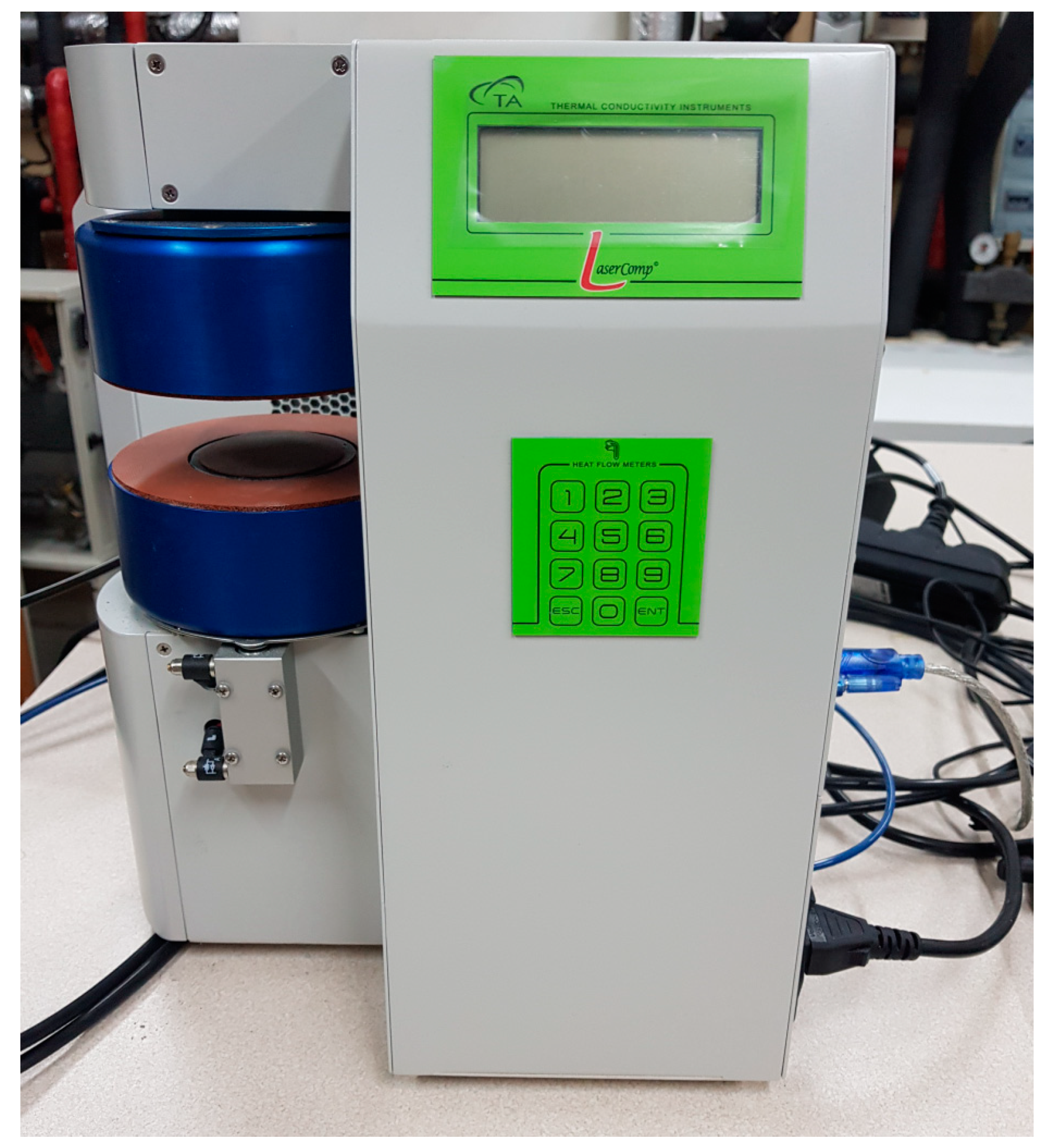
Moreover, the thermal conductivity of the prepared samples was tested. After the fresh sealing slurry had been properly prepared, it was also poured into specially prepared ring-shaped molds, about 1.2 cm high and 5 cm in diameter. The round samples after setting and taking out from the molds are shown in Figure 13. The FOX 50 device was used for the thermal conductivity tests (Figure 14). The FOX 50 device is designed to test the thermal conductivity of materials in the range of 0.1 WK−1m−1 to 10 WK−1m−1, equipped with a set of two round plates covered from the outside with a cylinder with an insulation layer. The upper plate is stationary and the lower one can move up and down by pneumatic mechanism. A digital thickness readout sensor monitors the position of the lower plate. Once the lower plate is moved down, a sample can be placed between the two plates. Each time the stack is closed, the average thickness of the sample is determined within +/−0.025 mm resolution. The thermocouples provide accurate readings of the both plates temperatures. Each plate has a powerful, and independently controlled thermoelectric (Peltier) element. The general principle of the FOX 50 heat flow meter instruments is based on the one-dimensional equation for Fourier–Biot law (1) [87]:
q = λ   ( d t d x )
where:
  • q: heat flux flowing through the sample, Wm−2,
  • λ: thermal conductivity of the sample, Wm−1K−1,
  • dt/dx: temperature gradient on the isotherm flat surface in the sample, Km−1.

4. Research Results and Analysis

Table 2, Table 3, Table 4 and Table 5 present the test results of the hardened sealing slurries. The effect of the graphene addition on the strength is shown in Figure 12.
The compressive strength is the highest stress that the test sample can withstand during the compression process. The bending strength is the greatest resistance that the sample exerts to external forces, causing bending until it breaks. During the bending strength test, the sample cracks in half. Hence, the compressive strength test can be performed on the two halves of the sample. Therefore, two results of the same sample are obtained. The final result for the compressive strength was given as the arithmetic mean of all measurements of a given type of sample. The data on the mechanical strength of the tested samples were obtained after independent calculations made by the press [88]. They are based on the Equation (2):
σ = F A
where:
  • σ: bending/compressive strength of the sample, MPa,
  • F: the smallest force exerted by the piston on the sample surface causing bending/compression, kN,
  • A: cross-sectional area, on which the piston acts during bending/compression of the sample (for bending, the strength value is calculated for the cross-sectional area A, and for compression, two strength values are calculated for the pressure plate area (compression surface) equal to 1600 mm2), mm2.
In the absence of graphene addition (formula A), the strength of the samples was 2.560 MPa for bending and 5.891 MPa for compression. Formulas B and D showed slight changes in these values and were, respectively, 2.571 MPa and 2.610 MPa for bending, and 5.681 MPa and 6.350 MPa for compression. Formula C, in which the addition of graphene was 0.1%, stands out in comparison to the previous two. Independently conducted research [89] confirms the thesis of strength increase with the 0.1% addition of graphene in relation to the zero sample (formula A) after 28 days.
The graph clearly shows the peak bending strength of 3.557 MPa and the compressive strength of 9.433 MPa. The obtained values for formula C relatively represent an increase of about 39% and 60% in relation to the zero samples. To show the level of linear dependence between the variables, the graph (Figure 12) contains the trend lines with the corresponding linear regression equation. A visible increase in bending and compressive strength with 0.1% graphene content can be noticed. This slurry can be considered the most advantageous in terms of the mechanical properties of the load-bearing piles.
In the future, the use of graphene structures larger than nanopowder will presumably increase the mechanical strength of load-bearing piles and reduce their thermal resistance [1].
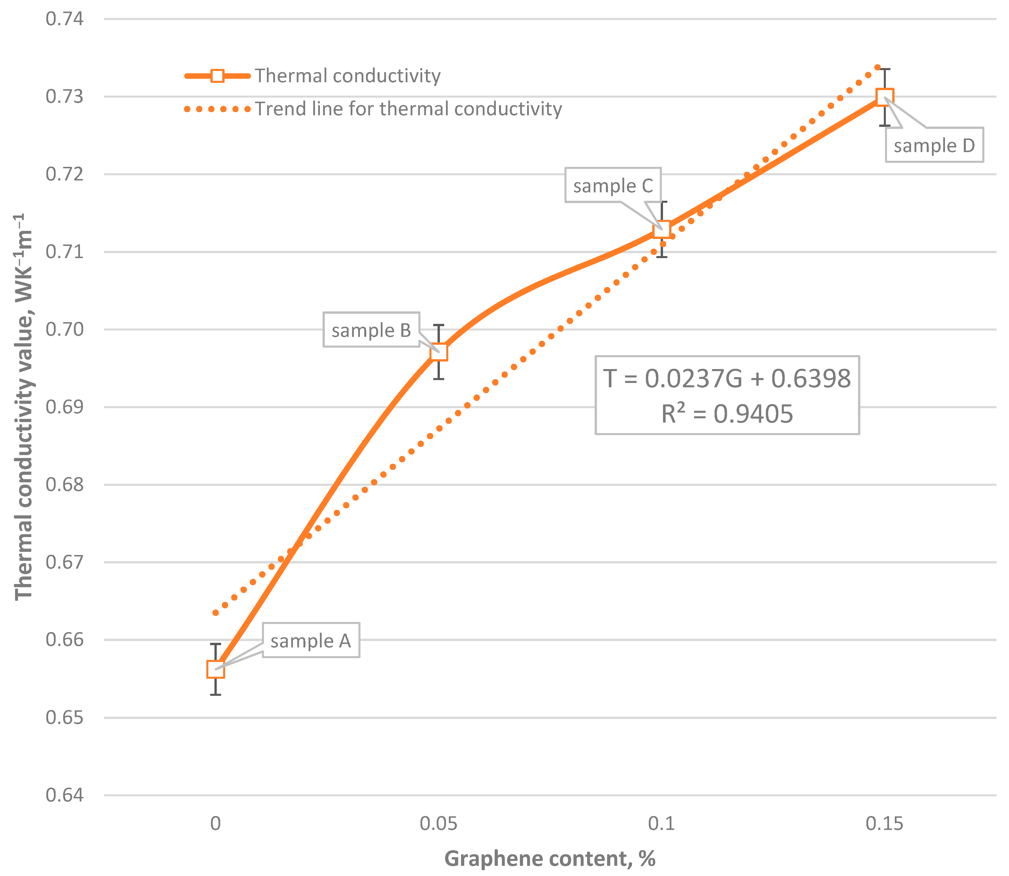
Thermal conductivity is a physical property of the body that describes the ability of a substance to transmit internal energy. Tests for its values were carried out on the FOX 50 device. The measurement results are presented in Table 6. The relationship between the thermal conductivity and the graphene percentage is shown in Figure 15.
In all cases, the change in the value of thermal conductivity of the tested recipes was compared with the base sample, i.e., recipe A. Recipe B shows an increase in thermal conductivity of the tested sample by 6.23% compared to the base sample. In the case of recipe C there was an increase by 8.64%, while the samples of the recipe D by 11.23%. The thermal conductivity value increased with the enhancement of graphene content in the sample. Research is currently underway on increasing the content of graphene in recipes. Based on the conducted research, it is concluded that the most promising recipe is the C formula, because it provides the highest value of strength, i.e., the critical parameter of special foundation which determines safety. Additionally, it significantly increases the thermal conductivity. Other thermal parameters of sealing slurries, such as specific heat capacity and thermal diffusivity, will be determined in further studies. In addition, in the future, after the execution of energy piles with the innovative slurry formulas described in this article, it is planned to conduct a thermal response test.
Information on graphene prices was obtained from the received company offers. A simplified economic analysis of the prices of sealing slurries recipes is presented below. It was made based on the average data from the received offers. The assumed exchange rate of 1 EUR was 4.50 PLN. In Poland, the average price of one ton of CEM I 42.5R Portland cement was about EUR 132 per Mg. The graphite used in the research cost EUR 1.4 per kilo and the price of graphene was EUR 965 per 100 grams. The analysis did not include the cost of PSP-042 due to the lack of data on current market prices. The cost of producing the mixture per one ton of cement used is as follows: recipe A: EUR 412, recipe B: EUR 5237, recipe C: EUR 10,060, recipe D: EUR 14,880. The current high price of graphene is the limitation of the described formula’s application.

5. Conclusions

The use of low-temperature geothermal energy in the world is still not very popular despite its potential. However, an increasing amount of research is leading to an increase in the performance of such systems. The result is the cost reduction of their implementation and operation. Ultimately, geothermal or air heat pumps should be used in heating, powered by electricity generated from other renewable sources. The scale effect will positively affect many investments of this type. Thermopiles are not limited by geographic location, climate, and the need for additional space, so they can be used practically anywhere. The operation of the system based on energy piles reduces the problem of negative impact and pollution of the environment, due to the closed circulation of the heat carrier preventing contamination of groundwater and low noise emission from the compressor GHP. Based on the results of research and their interpretation, the following conclusions were drawn:
  • Among the slurries tested on a hydraulic press after 28 days, the formula with the 0.1% graphene addition (formula C) turned out to be the one with definitely the best values of bending and compression strength;
  • based on the research, it can be concluded that the cement slurry with the 0.1% graphene addition may be used in future field applications during deep foundation works intending to draw energy from the rock mass. Currently, primarily the high price of graphene materials limits the implementation of such a solution to general use. The use of larger than nanopowder graphene structures will presumably have a positive effect on the mechanical strength increase in the piles and the reduction of their thermal resistance;
  • with the growth of graphene content in the sample, the value of thermal conductivity increases; the highest value of thermal conductivity was observed for sample D;
  • despite the highest thermal conductivity value of formula D, it can be concluded that formula C has the best chance of being used in energy piles.

Author Contributions

Conceptualization, T.S. and A.S.-Ś.; methodology, T.K.; software, T.W.; validation, I.K.; formal analysis, T.K.; investigation, T.W. and I.K.; resources, A.S.-Ś.; data curation, T.K.; writing—original draft preparation, T.W. and T.S.; writing—review and editing, A.S.-Ś. and T.K.; visualization, T.W.; supervision, T.S.; project administration, A.S.-Ś.; funding acquisition, T.S. All authors have read and agreed to the published version of the manuscript.

Funding

The research leading to these results has received funding from the Norway Grants 2014–2021 via the National Centre for Research and Development in Warsaw.

Conflicts of Interest

The authors declare no conflict of interest.

References

  1. Sapińska-Śliwa, A.; Rosen, M.A.; Gonet, A.; Kowalczyk, J.; Śliwa, T. A New Method Based on Thermal Response Tests for Determining Effective Thermal Conductivity and Borehole Resistivity for Borehole Heat Exchangers. Energies 2019, 12, 1072. [Google Scholar] [CrossRef] [Green Version]
  2. Crandall, A.C. House Heating with Earth Heat Pump. Electr. World 1946, 126/19, 94–95. [Google Scholar]
  3. Kemler, E.N. Methods of Earth Heat Recovery for the Heat Pump. Heat. Vent. 1947, 9/1947, 69–72. [Google Scholar]
  4. Ingersoll, L.R.; Adler, F.T.; Plass, H.J.; Ingersoll, A.C. Theory of Earth Heat Exchangers for the Heat Pump. ASHVE Trans. 1950, 56, 167–188. [Google Scholar]
  5. Sliwa, T. Wybrane systemy geotermalne w skałach suchych (Chosen geothermal systems in dry rocks). In Proceedings of the Konferencja Naukowa “Aktualny stan i perspektywy rozwoju górnictwa w aspekcie ochrony środowiska” (Conference on Current state and development prospects of mining in the aspect of environmental protection, proceedings), Dnipropetrovsk, Ukraine, 13–14 May 1996; pp. 307–312. [Google Scholar]
  6. Sliwa, T. Wybrane systemy geotermalne w aspekcie warunków geologicznych (Chosen geotermic systems in aspect of geology). Zeszyty Naukowe AGH Wiertnictwo Nafta Gaz. 1998, 15, 199–208. (In Polish) [Google Scholar]
  7. Sliwa, T.; Stryczek, S.; Wysogląd, T.; Skakuj, A.; Wiśniowski, R.; Sapińska-Śliwa, A.; Bieda, A.; Kowalski, T. Wpływ grafitu i diatomitu na parametry wytrzymałościowe stwardniałych zaczynów cementowych (Impact of graphite and diatomite on the strength parameters of hardened cement slurries). Przem. Chem. 2017, 96, 960–963. (In Polish) [Google Scholar]
  8. Sapińska-Śliwa, A. Efektywność Pozyskiwania ciepła z Górotworu w Aspekcie Sposobu Udostępniania Otworami Wiertniczymi (Effectiveness of Heat Recovery from Rock Mass in the Context of the Production Method by Means of Boreholes); Rozprawy Monografie Akademia Górniczo-Hutnicza im. Stanisława Staszica w Krakowie, 2019, no. 364; Wydawnictwa AGH UST: Kraków, Poland, 2019; p. 320. (In Polish) [Google Scholar]
  9. Sliwa, T.; Sapińska-Śliwa, A.; Knez, D.; Bieda, A.; Kowalski, T.; Złotkowski, A. Borehole Heat Exchangers, Production and Storage of Heat in the Rock Mass, Laboratory of Geoenergetics book series vol. 2, 1st ed.; Oil and Gas Foundation: Krakow, Poland, 2016; p. 177. [Google Scholar]
  10. Sliwa, T.; Kotyza, J. Application of Existing Wells as Ground Heat Source for Heat Pumps in Poland. Appl. Energy 2003, 74, 3–8. [Google Scholar] [CrossRef]
  11. Sliwa, T.; Rosen, M.A.; Jezuit, Z. Use of Oil Boreholes in the Carpathians in Geoenergetic Systems: Historical and Conceptual Review. Res. J. Environ. Sci. 2014, 8, 231–242. [Google Scholar] [CrossRef] [Green Version]
  12. Sliwa, T.; Rosen, M.A. Efficiency Analysis of Borehole Heat Exchangers as Grout Varies Via Thermal Response Test Simulations. Geothermics 2017, 69, 132–138. [Google Scholar] [CrossRef]
  13. Mayfield, M. ICT in BSF Environmental Challenges an Engineer’s View (presentation ppt). Available online: https://www.partnershipsforschools.org.uk/index.html (accessed on 15 January 2019).
  14. 14. Vasilescu, A-R. Design and Execution of Energy Piles: Validation by In-Situ and Laboratory Experiments. Doctorate Thesis, L’École Centrale de Nantes, Nantes, France, 5 December 2019.
  15. Sliwa, T.; Rosen, M.A. Natural and Artificial Methods for Regeneration of Heat Resources for Borehole Heat Exchangers to Enhance the Sustainability of Underground Thermal Storages: A Review. Sustainability 2015, 7, 13104–13125. [Google Scholar] [CrossRef] [Green Version]
  16. Grabowski, Z.; Pisarczyk, S.; Obrycki, M. Fundamentowanie, 5th ed.; Oficyna Wydawnicza Politechniki Warszawskiej: Warszawa, Poland, 2005; p. 228. (In Polish) [Google Scholar]
  17. Stryczek, S.; Gonet, A. Geoinżynieria, 1st ed.; Wydawnictwo Instytutu Gospodarki Surowcami Mineralnymi i Energią PAN: Kraków, Poland, 2000; p. 153. (In Polish) [Google Scholar]
  18. Sliwa, T.; Gonet, A.; Ostrowska, K. Możliwości pozyskania ciepła z ośrodka gruntowego za pośrednictwem pali nośnych (Possibility of heat extracting from ground by foundation piles). Technika Poszukiwań Geologicznych. Geotermia, Zrównoważony Rozwój 2007, 46, 85–89. (In Polish) [Google Scholar]
  19. Gonet, A.; Sliwa, T.; Stryczek, S.; Sapińska-Śliwa, A.; Jaszczur, M.; Pająk, L.; Złotkowski, A. Metodyka Identyfikacji Potencjału Cieplnego Górotworu Wraz z Technologią Wykonania i Eksploatacji Otworowych Wymienników Ciepła, 1st ed.; Wydawnictwa AGH: Krakow, Poland, 2011; p. 440. (In Polish) [Google Scholar]
  20. Schröder, B.; Hanschke, T. Energiepfhähle-umweltfreundliches Heizen und Kühlen mit geothermisch aktivierten Stahlbetonfertigpfählen. Bautechnik 2003, 80, 925–927. [Google Scholar]
  21. Brandl, H. Energy Foundations and Other Thermo Active Ground Structures. Geotechnique 2006, 56, 81–122. [Google Scholar] [CrossRef]
  22. Amis, T.; Loveridge, F. Energy Piles and Other Thermal Foundations for GSHP - Developments in UK Practice and Research. REHVA J. 2014, 32–35. [Google Scholar]
  23. Desmedt, J.; Hoes, H. Case Study of a BTES and Energy Piles Application for a Belgian Hospital. In Proceedings of the Proceedings ECOSTOCK 2006, New Jersey, US, The Richard Stockton College of New Jersey. 2006. Available online: http://citeseerx.ist.psu.edu/viewdoc/download?doi=10.1.1.507.2234&rep=rep1&type=pdf (accessed on 10 March 2020).
  24. Koene, F.G.H.; van Helden, W.G.J.; Romer, J.C. Energy Piles as Cost Effective Ground Heat Exchangers. In Proceedings of the Proceedings TERRASTOCK 2000, Stuttgart, Germany, 28 August–1 September 2000; pp. 227–232. [Google Scholar]
  25. Pahud, D.; Hubbuch, M. Measured Thermal Performance of the Energy Pile System of the Dock Midfield of Zurich Airport. In Proceedings of the Proceedings European Geothermal Congress 2007, Unterhaching, Germany, 30 May–1 June 2007; Available online: https://www.geothermal-energy.org/pdf/IGAstandard/EGC/2007/195.pdf (accessed on 10 March 2020).
  26. Poulsen, S.E.; Alberdi-Pagola, M.A.; Cerra, D.; Magrini, A. An Experimental and Numerical Case Study of Passive Building Cooling with Foundation Pile Heat Exchangers in Denmark. Energies 2019, 12, 2697. [Google Scholar] [CrossRef] [Green Version]
  27. Lennon, D.J.; Watt, E.; Suckling, T.P. Energy Piles in Scotland. In Proceedings of the Fifth International Conference Deep Found Bored Auger Piles, Frankfurt, Germany, 15 May 2009. [Google Scholar]
  28. Fadajev, J.; Simson, R.; Kurnitski, J.; Haghighat, F. A Review on Energy Piles Design, Sizing and Modelling. Energy 2017, 1221, 390–407. [Google Scholar] [CrossRef]
  29. Sung, C.; Park, S.; Lee, S.; Oh, K.; Choi, H. Thermo-Mechanical Behavior of Cast-In-Place Energy Piles. Energy 2018, 161, 920–938. [Google Scholar] [CrossRef]
  30. Park, S.; Lee, D.; Lee, S.; Chauchois, A.; Choi, H. Experimental and Numerical Analysis on Thermal Performance of Large-Diameter Cast-In-Place Energy Pile Constructed in Soft Ground. Energy 2017, 118, 297–311. [Google Scholar] [CrossRef]
  31. Sani, A.K.; Singh, R.M.; Amis, T.; Cavarretta, I. A Review on the Performance of Geothermal Energy Pile Foundation, Its Design Process and Applications. Renew. Sustain. Energy Rev. 2019, 106, 54–78. [Google Scholar] [CrossRef]
  32. Zhao, Q.; Chen, B.; Tian, M.; Liu, F. Investigation on the Thermal Behavior of Energy Piles and Borehole Heat Exchangers: A Case Study. Energy 2018, 1621, 787–797. [Google Scholar] [CrossRef]
  33. Moon, C.E.; Choi, J.M. Heating Performance Characteristics of the Ground Source Heat Pump System with Energy-Piles and Energy-Slabs. Energy 2015, 811, 27–32. [Google Scholar] [CrossRef]
  34. Cecinato, F.; Loveridge, F.A. Influences on the Thermal Efficiency of Energy Piles. Energy 2015, 82, 1021–1033. [Google Scholar] [CrossRef]
  35. Tsubaki, K.; Mitsutake, Y. Performance of Ground-Source Heat Exchangers Using Short Residential Foundation Piles. Energy 2016, 1041, 229–236. [Google Scholar] [CrossRef]
  36. Rychlewski, P.; Jurasz, W.; Sierant, J. Fundamenty palowe–jako elementy instalacji pozyskującej energię cieplną z gruntu w instalacjach pomp ciepła—Termopale. Inżynier budownictwa 2014, 113, 88–94. (In Polish) [Google Scholar]
  37. Park, S.; Lee, D.; Choi, H.J.; Jung, K.; Choi, H. Relative Constructability and Thermal Performance of Cast-In-Place Concrete Energy Pile: Coil-Type GHEX (Ground Heat Exchanger). Energy 2015, 811, 56–66. [Google Scholar] [CrossRef]
  38. Sliwa, T.; Sojczyńska, A.; Rosen, M.A.; Kowalski, T. Evaluation of Temperature Profiling Quality in Determining Energy Efficiencies of Borehole Heat Exchangers. Geothermics 2019, 78, 129–137. [Google Scholar] [CrossRef]
  39. Mousa, M.M.; Bayom, A.M.; Saghir, M.Z. Experimental and Numerical Study on Energy Piles with Phase Change Materials. Energies 2020, 13, 4699. [Google Scholar] [CrossRef]
  40. Lyu, W.; Pu, H.; Chen, J. Thermal Performance of an Energy Pile Group with a Deeply Penetrating U-Shaped Heat Exchanger. Energies 2020, 13, 5822. [Google Scholar] [CrossRef]
  41. Jalaluddin; Miyara, A.; Tsubaki, K.; Inoue, S.; Yoshida, K. Experimental Study of Several Types of Ground Heat Exchanger Using a Steel Pile Foundation. Renew. Energy 2011, 36, 764–771. [Google Scholar]
  42. Zarrella, A.; DeCarli, M.; Galgaro, A. Thermal Performance of Two Types of Energy Foundation Pile: Helical Pipe and Triple U-tube. Appl. Therm. Eng. 2013, 61, 301–310. [Google Scholar] [CrossRef]
  43. Bezyan, B.; Porkhial, S.; Mehrizi, A.A. 3-D Simulation of Heat Transfer Rate in Geothermal Pile-Foundation Heat Exchangers with Spiral Pipe Configuration. Appl. Therm. Eng. 2015, 87, 655–668. [Google Scholar] [CrossRef]
  44. Zhao, Q.; Liu, F.; Liu, C.; Tian, M.; Chen, B. Influence of Spiral Pitch on the Thermal Behaviors of Energy Piles with Spiral-Tube Heat Exchanger. Appl. Therm. Eng. 2017, 125, 1280–1290. [Google Scholar] [CrossRef]
  45. Saeidi, R.; Noorollahi, Y.; Esfahanian, V. Numerical Simulation of a Novel Spiral Type Ground Heat Exchanger for Enhancing Heat Transfer Performance of Geothermal Heat Pump. Energy Convers. Manag. 2018, 168, 296–307. [Google Scholar] [CrossRef]
  46. Cui, P.; Li, X.; Man, Y.; Fang, Z. Heat Transfer Analysis of Pile Geothermal Heat Exchangers with Spiral Coils. Applied Energy 2011, 88, 4113–4119. [Google Scholar] [CrossRef]
  47. Huang, G.; Yang, X.; Liu, Y.; Zhuang, C.; Zhang, H.; Lu, J. A Novel Truncated Cone Helix Energy Pile: Modelling and Investigations of Thermal Performance. Energy Build. 2018, 158, 1241–1256. [Google Scholar] [CrossRef]
  48. Go, G.H.; Lee, S.R.; Kang, H.B.; Yoon, S.; Kim, M.J. A Novel Hybrid Design Algorithm for Spiral Coil Energy Piles that Considers Groundwater Advection. Appl. Therm. Eng. 2015, 78, 196–208. [Google Scholar] [CrossRef]
  49. Yoon, S.; Lee, S.R.; Xue, J.; Zosseder, K.; Go, G.H.; Park, H. Evaluation of the Thermal Efficiency and a Costanalysis of Different Types of Ground Heat Exchangers in Energy Piles. Energy Convers. Manag. 2015, 105, 393–402. [Google Scholar] [CrossRef]
  50. Zhao, Q.; Chen, B.; Liub, B. Study on the Thermal Performance of Several Types of Energy Pile Ground Heat Exchangers: U-Shaped, W-Shaped and Spiral-Shaped. Energy Build. 2016, 133, 335–344. [Google Scholar] [CrossRef]
  51. Sliwa, T.; Nowosiad, T.; Vytyaz, O.; Sapińska-Śliwa, A. Study on the Efficiency of Deep Borehole Heat Exchangers. SOCAR Proc. 2016, 2, 29–42. [Google Scholar] [CrossRef]
  52. Olgun, C.G. Design Considerations of Energy Piles. In Proceedings of the International Bridge Conference, Pittsburgh, PA, UAS, 7 June 2011. [Google Scholar]
  53. Suckling, T. Geothermal Energy and Energy Piles, Stent Foundations Ltd., UK. Personal communication, 2008. [Google Scholar]
  54. Maca, N.; Ryżyński, G. Termopale–termoaktywne elementy posadowień obiektów budowlanych (TITAN Polska). XI Międzynarodowe Targi Geologiczne GEO-EKO-TECH. 8–9 May 2013. Available online: https://www.pgi.gov.pl/docman-tree/wydarzenia/targi/1765-geologia-2013-termopale/file.html (accessed on 22 February 2021). (In Polish)
  55. Skanska. Available online: www.skanska.co.uk (accessed on 15 January 2019).
  56. Bourne-Webb, P. Observed Response of Energy Geostructures. In Energy Geostructures Innovation in Underground Engineering; Laloui, L., Di Donna, A., Eds.; Wiley: London, UK, 2013; pp. 45–67. [Google Scholar]
  57. Dyrektywa Parlamentu Europejskiego i Rady 2010/31/UE z dnia 19 maja 2010 roku w sprawie charakterystyki energetycznej budynków, Dziennik Urzędowy Unii Europejskiej, L 153/13, 18.6.2010. Available online: https://eur-lex.europa.eu/legal-content/PL/TXT/PDF/?uri=CELEX:32010L0031&from=EL (accessed on 23 January 2019). (In Polish).
  58. Ferrantelli, A.; Fadejev, J.; Kurnitski, J. Energy Pile Field Simulation in Large Buildings: Validation of Surface Boundary Assumptions. Energies 2019, 12, 770. [Google Scholar] [CrossRef] [Green Version]
  59. Alberdi-Pagola, M.; Poulsen, S.E.; Jensen, R.L.; Madsen, S. Thermal Design Method for Multiple Precast Energy Piles. Geothermics 2019, 78, 201–210. [Google Scholar] [CrossRef]
  60. Caulk, R.; Ghazanfari, E.; McCartney, J.S. Parameterization of a Calibrated Geothermal Energy Pile Model. Geomech. Energy Environ. 2016, 5, 1–15. [Google Scholar] [CrossRef] [Green Version]
  61. Dupray, F.; Laloui, L.; Kazangba, A. Numerical Analysis of Seasonal Heat Storage in an Energy Pile Foundation. Comput. Geotech. 2014, 55, 67–77. [Google Scholar] [CrossRef]
  62. Loria, A.F.R.; Vadrot, A.; Laloui, L. Analysis of the Vertical Displacement of Energy Pile Groups. Geomech. Energy Environ. 2018, 16, 1–14. [Google Scholar] [CrossRef]
  63. Cristodoulides, P.; Vieira, A.; Lenart, S.; Maranha, J.; Vidmar, G.; Popov, R.; Georgiev, A.; Aresti, L.; Florides, G. Reviewing the Modeling Aspects and Practices of Shallow Geothermal Energy Systems. Energies 2020, 13, 4273. [Google Scholar] [CrossRef]
  64. Park, H.; Lee, S.R.; Yoon, S.; Choi, J.C. Evaluation of Thermal Response and Performance of PHC Energy Pile: Field Experiments and Numerical Simulation. Appl. Energy 2013, 103, 12–24. [Google Scholar] [CrossRef]
  65. Laloui, L.; Sutman, M. Experimental Investigation of Energy Piles: From Laboratory to Field Testing. Geomech. Energy Environ. 2020. [Google Scholar] [CrossRef]
  66. Sliwa, T.; Gonet, A. Theoretical Model of Borehole Heat Exchanger. J. Energy Resour. Technol. 2005, 127, 142–148. [Google Scholar] [CrossRef]
  67. Al-Khoury, R.; Kölbel, T.; Schramedei, R. Efficient Numerical Modeling of Borehole Heat Exchangers. Comput. Geosci. 2010, 36, 1301–1315. [Google Scholar] [CrossRef]
  68. Bauer, D.; Heidemann, W.; Diersch, H.J. Transient 3D Analysis of Borehole Heat Exchanger Modeling. Geothermics 2011, 40, 250–260. [Google Scholar] [CrossRef]
  69. Sliwa, T.; Gołaś, A.; Wołoszyn, J.; Gonet, A. Numerical Model of Borehole Heat Exchanger in ANSYS CFX Software. Arch. Min. Sci. 2012, 57, 375–390. [Google Scholar]
  70. Fadejev, J.; Kurnitski, J. Geothermal Energy Piles and Boreholes Design with Heat Pump in a Whole Building Simulation Software. Energy Build. 2015, 106, 23–34. [Google Scholar] [CrossRef]
  71. Loveridge, F.A.; Olgun, G.; Brettmann, T.; Powrie., W. Group Thermal Response Testing for Energy Piles. In Proceedings of the XVI European Conference for Soil Mechanics and Geotechnical Engineering, Edinburgh, UK, 13–17 September 2015; pp. 2595–2600. [Google Scholar]
  72. Sapińska-Śliwa, A.; Sliwa, T.; Twardowski, K.; Szymski, K.; Gonet, A.; Żuk, P. Method of Averaging the Effective Thermal Conductivity Based on Thermal Response Tests of Borehole Heat Exchangers. Energies 2020, 13, 3737. [Google Scholar] [CrossRef]
  73. Gehlin, S.; Eklof, C. A Mobile Equipment for Thermal Response Test. Master’s Thesis, Luleå University of Technology, Luleå, Sweden, January 1996. [Google Scholar]
  74. Spitler, J.D.; Gehlin, S.E.A. Thermal Response Testing for Ground Source Heat Pump Systems—An Historical Review. Renew. Sustain. Energy Rev. 2015, 50, 1125–1137. [Google Scholar] [CrossRef]
  75. Acuña, J.; Mogensen, P.; Palm, B. Distributed Thermal Response Test on a U-Pipe Borehole Heat Exchanger. In Proceedings of the Effstock 2009, 11th International Conference on Thermal Energy Storage, Stockholm, Sweden, 14–17 June 2009. [Google Scholar]
  76. Banks, D.; Withers, J.; Freeborn, R. An Overview of the Results of In-Situ Thermal Response Testing in the UK. In Proceedings of the 11th International Conference on Thermal Energy Storage for Efficiency and Sustainability, Stockholm, Sweden, 14–17 June 2009. [Google Scholar]
  77. Jensen-Page, L.; Loveridge, F.; Narsillio, G.A. Thermal Response Testing of Large Diameter Energy Piles. Energies 2019, 12, 2700. [Google Scholar] [CrossRef] [Green Version]
  78. Ozudogru, T.; Brettmann, T.; Olgun, G.; Martin, J.; Senol, A. Thermal Conductivity Testing of Energy Piles: Field Testing and Numerical Modeling. In Proceedings of the Geo-Congress, Oakland, CA, USA, 25–29 March 2012. [Google Scholar]
  79. Franco, A.; Moffat, R.; Toledo, M.; Herrera, P. Numerical Sensitivity Analysis of Thermal Response Tests (TRT) in Energy Piles. Renew. Energy 2016, 86, 985–992. [Google Scholar] [CrossRef]
  80. Hu, P.; Zha, J.; Lei, F.; Zhu, N.; Wu, T. A Composite Cylindrical Model and Its Application in Analysis of Thermal Response and Performance for Energy Pile. Energy Build. 2014, 84, 324–332. [Google Scholar] [CrossRef]
  81. Fossa, M.; Priarone, A.; Silenzi, F. Superposition of the Single Point Source Solution to Generate Temperature Response Factors for Geothermal Piles. Renew. Energy 2020, 145, 805–813. [Google Scholar] [CrossRef]
  82. Giergiczny, Z.; Batóg, M.; Dziuk, D.; Golda, A.; Grabski, J.; Kaszuba, S.; Sokołowski, M.; Synowiec, K.; Szuba, J.; Wąsik, M. Górażdże Cement, Kruszywa Beton - Rodzaje, Właściwości, Zastosowanie; Górażdze: Chorula, Poland, 2016; p. 399. (In Polish) [Google Scholar]
  83. Sapińska-Śliwa, A.; Sliwa, T.; Wiśniowski, R. Grafit i diatomit jako dodatki do zaczynów uszczelniających otwory w geotermii (Graphite and diatomite as additives for grouts for boreholes in geothermics). Przemysł Chemiczny 2017, 96, 1723–1725. (In Polish) [Google Scholar]
  84. API. Specification for Materials and Testing for well Cements; API SPEC 10A; American Petroleum Institute: Washington, DC, USA, December 2010. [Google Scholar]
  85. Polski Komitet Normalizacyjny, Przemysł Naftowy i Gazowniczy—Cementy i Materiały do Cementowania Otworów Wiertniczych—Część 2: Badania Cementów Wiertniczych; PN-EN ISO 10426-2:2006; Polski Komitet Normalizacyjny: Warszawa, Poland, 18 May 2006. (In Polish)
  86. Polski Komitet Normalizacyjny. In Cementy i Zaczyny Cementowe do Cementowania w Otworach Wiertniczych; PN-85-G-02320; Polski Komitet Normalizacyjny: Warszawa, Poland, 1985. (In Polish)
  87. FOX 50 instrument manual, LaserComp–TA Instruments, CD Version 2018.
  88. Polski Komitet Normalizacyjny. In Metody badania cementu—Część 1: Oznaczanie wytrzymałości; PN-EN 196-1:2016-07; Polski Komitet Normalizacyjny: Warszawa, Poland, 12 January 2018. (In Polish)
  89. Bai, S.; Jiang, L.; Xu, N.; Jin, M.; Jiang, S. Enhancement of Mechanical and Electrical Properties of Graphene/Cement Composite due to Improved Dispersion of Graphene by Addition of Silica Fume. Constr. Build. Mater. 2018, 164, 433–441. [Google Scholar] [CrossRef]
Figure 1. (a) Piling machine (b) Auger.
Energies 14 01190 g001
Figure 2. Installation diagram with ground source heat pumps (GSHPs) and BHEs, (a) two BHEs with double supply U-tubes, connected to the evaporator or GSHP condenser inside the building, (b) visualization of a building with GSHP and BHEs [13].
Energies 14 01190 g002
Figure 3. (a) The reinforcement of the energy pile, (b) the insertion of the reinforcement in the form of a basket equipped with a U-tube system into the borehole [52].
Energies 14 01190 g003
Figure 4. An example of an energy pile, (a) the interior of the pile reinforcement with arranged pipes [53], (b) pipe arrangement in a reinforcing structure (slurry wall) [54].
Energies 14 01190 g004
Figure 5. Laying the heat exchanger pipes in the load-bearing pile structure [55].
Energies 14 01190 g005
Figure 6. Execution of the energy piles in Krakow (the building of the National Archives), (a) reinforcement of the energy pile with an I-beam with a welded circular element, (b) execution of the energy pile.
Energies 14 01190 g006
Figure 7. (a) A photo of the energy piles layout for the building of the National Archives in Krakow, and (b) a photo with a thermal imaging camera.
Energies 14 01190 g007
Figure 8. (a) and (b) examples of individual energy piles at the construction site of the National Archives in Krakow (a thermal image).
Energies 14 01190 g008
Figure 9. The molds for the beams.
Energies 14 01190 g009
Figure 10. An example of a standard beam subjected to strength testing.
Energies 14 01190 g010
Figure 11. Hydraulic press Servo-Plus Evolution E183.
Energies 14 01190 g011
Figure 12. The relationship between the strength of cement samples (S) and the graphene percentage (G).
Energies 14 01190 g012
Figure 13. An example of a prepared round samples subjected to thermal conductivity testing.
Energies 14 01190 g013
Figure 14. FOX 50: thermal conductivity measurement apparatus.
Energies 14 01190 g014
Figure 15. The relationship between the thermal conductivity (T) and the graphene percentage (G).
Energies 14 01190 g015
Table 1. The formulas of the individual cement slurries.
w/c = 1.0
Sample NameABCD
Graphene percentage%00.050.10.15
Waterg1500150015001500
Solid ingredientsGrapheneg00.751.52.25
Graphiteg300300300300
Cementg1500150015001500
PSP-042g6666
Sumg18061806.751807.51808.25
Table 2. Strength test results of the hardened sealing slurries: sample A.
SampleA
w/c1.01.01.0
cement, g150015001500
water, g150015001500
graphite, g300300300
graphene 12 nm, g000
PSP-042, g666
sample dimensions, cm4 × 3.96 × 164 × 4.00 × 164 × 4.00 × 16
cross-sectional area of the crushed sample, A, mm2422.4426.7426.7
minimum bending force, Fz, kN1.161.1160.987
flexural strength, σz, MPa2.7532.6152.312
minimum compressive force of the 1st half, Fs1, kN11.00710.5647.771
minimum compressive force of the 2nd half, Fs2, kN10.6568.9427.393
compressive strength of the 1st half (A1), σs1, MPa6.9496.6034.857
compressive strength of the 2nd half (A2), σs2, MPa6.7275.5894.621
average bending strength, avr. σz, MPa2.560
standard deviation for bending strength, MPa0.184
average compressive strength, avr. σs, MPa5.891
standard deviation for the compressive strength, MPa0.922
Table 3. Strength test results of the hardened sealing slurries: sample B.
SampleB
w/c1.01.01.0
cement, g150015001500
water, g150015001500
graphite, g300300300
graphene 12 nm, g0.750.750.75
PSP-042, g666
sample dimensions, cm4 × 3.9 × 164 × 3.96 × 164 × 4.04 × 16
cross-sectional area of the crushed sample, A, mm2416.0422.4430.9
minimum bending force, Fz, kN1.1191.1001.042
flexural strength, σz, MPa2.6892.6052.419
minimum compressive force of the 1st half, Fs1, kN9.4869.0439.283
minimum compressive force of the 2nd half, Fs2, kN8.4999.2928.462
compressive strength of the 1st half (A1), σs1, MPa6.0815.7095.744
compressive strength of the 2nd half (A2), σs2, MPa5.4485.8665.237
average bending strength, avr. σz, MPa2.571
standard deviation for bending strength, MPa0.113
average compressive strength, avr. σs, MPa5.681
standard deviation for the compressive strength, MPa0.274
Table 4. Strength test results of the hardened sealing slurries: sample C.
SampleC
w/c1.01.01.0
cement, g150015001500
water, g150015001500
graphite, g300300300
graphene 12 nm, g1.51.51.5
PSP-042, g666
sample dimensions, cm4 × 3.92 × 164 × 3.86 × 164 × 3.97 × 16
cross-sectional area of the crushed sample, A, mm2418.1411.7423.5
minimum bending force, Fz, kN1.5441.2231.697
flexural strength, σz, MPa3.6922.9714.008
minimum compressive force of the 1st half, Fs1, kN15.12714.07614.657
minimum compressive force of the 2nd half, Fs2, kN15.72613.9215.183
compressive strength of the 1st half (A1), σs1, MPa9.6479.1179.230
compressive strength of the 2nd half (A2), σs2, MPa10.039.0159.561
average bending strength, avr. σz, MPa3.557
standard deviation for bending strength, MPa0.434
average compressive strength, avr. σs, MPa9.433
standard deviation for the compressive strength, MPa0.350
Table 5. Strength test results of the hardened sealing slurries: sample D.
SampleD
w/c1.01.01.0
cement, g150015001500
water, g150015001500
graphite, g300300300
graphene 12 nm, g2.252.252.25
PSP-042, g666
sample dimensions, cm4 × 3.77 × 164 × 3.76 × 164 × 3.82 × 16
cross-sectional area of the crushed sample, A, mm2402.1401.1407.5
minimum bending force, Fz, kN1.2021.0710.884
flexural strength, σz, MPa2.9892.6712.170
minimum compressive force of the 1st half, Fs1, kN10.30610.0118.886
minimum compressive force of the 2nd half, Fs2, kN9.9379.6248.868
compressive strength of the 1st half (A1), σs1, MPa6.8346.6565.816
compressive strength of the 2nd half (A2), σs2, MPa6.596.3995.804
average bending strength, avr. σz, MPa2.610
standard deviation for bending strength, MPa0.337
average compressive strength, avr. σs, MPa6.350
standard deviation for the compressive strength, MPa0.402
Table 6. Thermal conductivity test results of the hardened sealing slurries: all samples.
w/c = 1.0
Sample NameABCD
w/c 1.01.01.01.0
cementg1500150015001500
waterg1500150015001500
graphite,g300300300300
graphene 12 nmg00.751.52.25
PSP-042g6666
thermal conductivity measurements:
no. 1WK−1m−10.64580.69520.72190.7314
no. 2WK−1m−10.65660.69760.70560.7412
no. 3WK−1m−10.66380.68620.71580.7292
no. 4WK−1m−10.65170.70990.72160.7195
no. 5WK−1m−10.65920.71980.71590.7300
no. 6WK−1m−10.67000.68990.70620.7241
no. 7WK−1m−10.65890.69030.70990.7368
no. 8WK−1m−10.64320.69520.70040.7227
no. 9WK−1m−10.66020.69990.71590.7285
no. 10WK−1m−10.65210.68700.71580.7359
average thermal conductivityWK−1m−10.65620.69710.71290.7299
standard deviation thermal conductivityWK−1m−10.00770.01010.00670.0064
Publisher’s Note: MDPI stays neutral with regard to jurisdictional claims in published maps and institutional affiliations.

