Communication

DEAP Actuator Composed of a Soft Pneumatic Spring Bias with Pressure Signal Sensing

Faculty of Control, Robotics and Electrical Engineering, Poznan University of Technology, 60-965 Poznań, Poland
*
Author to whom correspondence should be addressed.
Energies 2021, 14(4), 1189; https://doi.org/10.3390/en14041189
Submission received: 21 December 2020 / Revised: 15 February 2021 / Accepted: 19 February 2021 / Published: 23 February 2021
(This article belongs to the Special Issue Bio-Inspired Materials for Energy and Environmental Applications)

Abstract

:
Dielectric electroactive actuators are novel and significant smart actuators. The crucial aspect of construction of these devices is the bias mechanism. The current literature presents three main types of biases used in the construction of the DEAP actuators. In these solutions, the bias is caused by the action of a spring, a force of a permanent magnet or an applied mass. The purpose of this article is to present a novel type of DEAP bias mechanism using soft pneumatic spring. In contrast to the solutions presented so far, the soft pneumatic spring has been equipped with a sensor that measures the variable pressure of its inner chamber. We performed the modeling process of a soft pneumatic spring with the finite element method to predict its mechanical behavior. Furthermore, a prototype of the soft spring was molded and used to construct a dielectric electroactive polymer actuator. The principle of operation has been confirmed by the experiments with measurement of static and dynamics characteristics. The presented device can be used to control systems with an additional pressure-sensing feedback.

1. Introduction

Dielectric Electroactive Polymers (DEAP) actuators are a new type of intelligent transducers [1]. The most important features of these new generation actuators are silent work, fast response and low cost [1,2]. Due to their features, this type of actuators is often called artificial muscles [1]. Furthermore, the flexibility of DEAP actuators follows the recent trend of soft robotics [3]. Currently, DEAP actuators are widely investigated by researches [4,5,6,7]. The recent practical developments like pumps for soft robotics or speakers shows the wide range of applicability of these devices [7,8,9]. It is also worth mentioning that DEAP actuators require a high voltage to operate. The high voltage can be generated by commercially available amplifiers or open-source projects [10].
To successfully design DEAP actuators the operating principle must be well understood. The crucial aspects of DEAP actuators are the properties of elastic membranes applied to build an electroactive layer. The membrane has characteristics of hyperelasticity and viscosity, causing different behaviors in the steady state and transient domains [11,12]. Furthermore, the viscoelastity causes hystersis in the response between voltage and displacement [13]. To better understand the behavior of DEAP actuators, two kinds of models were built. Control-oriented models are presented, for instance, in [2,12]. Furthermore, Finite Element Modeling (FEM) is also applied to describe the behavior of DEAP in details. Examples of FEM models can be seen presented in [14,15].
DEAP actuators can operate with different signals as input and output. The most popular configuration is to apply the voltage as input and take the displacement as output [2,16]. The wide range of displacement that is useful for practical applications can be obtained via a biasing mechanism. There are various possibilities of creating the bias. The most popular is to provide a mechanical spring [2,6,17]. The interesting application of nonlinear mechanical spring bias is to provide a wide range of operation [18]. Furthermore, the double spring system can assure applicability of high force [6]. A different approach to creating the bias is to apply magnetic coupling. The insertion of two permanent magnets can provide contactless bias. This application of bias was used in creating pump systems [5,7,19]. The simplest bias is loading the membrane with mass [12,20,21]. It was initially used to apply different working conditions for DEAP actuators. Additionally, the mass-bias system creates a highly under-damped system. In the works presented above, a single DEAP membrane was applied. In the newest configurations, double cone DEAP actuators have been reported. For instance, the application of a double DEAP membrane and single bias causes output power improvement [16,22]. In our work, we constructed an alternative bias with soft pneumatic bias. In general, soft pneumatic devices have recently been a very popular research direction due to their features, including softness, high durability and ease of design. For instance, soft pneumatic devices have been applied to build robotics systems [23,24].
In this study, a soft pneumatic spring is applied to create a biasing system. The varying pressure inside the spring chamber allows to obtain an additional sensing signal for a system. To achieve the goal, the soft pneumatic spring was modeled with the finite element method. Then, the prototype of spring was molded from silicone using foundry molds printed with a 3D printer. The static characteristics of the spring were measured and compared with simulations. Furthermore, the DEAP actuator biased by a soft pneumatic spring was assembled. The responses of pressure and distance were measured for step response and frequency response to examine the behavior of the new device.

2. The Concept of Soft Pneumatic Spring Bias

DEAP actuators are constructed with an elastic membrane that is coated with electrodes. The electroactive membrane is biased to obtain a wide range of movement. In existing solutions the bias was constructed with a spring, a permanent magnet and mass. The principle of bias with a different force source is presented in Figure 1. The spring (Figure 1a) is the most popular solution that provides independence from gravity. The application of nonlinear spring allows to obtain a wide range of actuator motion [2,6]. Magnetic bias (Figure 1b) was applied to build the pump [7,19]. It provides the possibility of contactless force generation. The mass bias (Figure 1c) depends on the gravity and therefore is less practical. However, it enables us to examine the properties of DEAP membranes or create a system with high and low damped oscillations [12,21].
In our work, we design a novel soft pneumatic bias for a DEAP actuator. The concept of the bias is presented in Figure 2. We can consider three cases. In the first case presented in Figure 2a, the DEAP membrane is alone and it does not have contact with the soft spring. This mode was analyzed by research in the early study of DEAP actuators. The switching voltages only causes a change to the stretching of the membrane, as is for instance shown in work [4]. The displacement in the vertical direction is minimal. Therefore, the following procedure (which is also known as spring or magnetic bias [16,18]) is applied to increase the displacement in the vertical direction. In the second case, shown in Figure 2b, the soft pneumatic spring bends a DEAP membrane without applied voltage. The membrane is deformed and the soft spring is compressed. Now, the pressure sensor is attached to the chamber through a tube. Because the voltage is off, the current state of the device can be called initial and marked by volume V 0 , pressure p 0 and distance d 0 . In the third step, presented in Figure 2c, the voltage is switched on. This causes Maxwell stress to act on the membrane electrodes and hence the membrane is compressed. Due to the elasticity of the membrane, the compression of the membrane causes the membrane to extend radially. Therefore, the membrane is bended further and the distance d 1 is greater than d 0 . Furthermore, the volume V 1 and pressure p 1 are also different. If the voltage is turned off, the membrane comes back to the second state. Therefore, the voltage can control the distance d and pressure p. In our work, we would like to examine the behavior of volume and pressure for various voltage input signals. In our concept, the soft pneumatic bias gives the possibility to provide a spring-like bias, but thanks to an internal chamber it also provides a pressure signal for sensing.

FEM Model

In the first step of the construction, a FEM model of a soft pneumatic spring alone was created. The model enables to predict the stiffness of the spring and its behavior. We assume that the spring is made from silicon with low hardness (about 25 on the Shore A scale). Therefore, the Young module for simulation is calculated based on the comparison between Young modules and Shore hardness [25]. In our work, we take into account the following approximation:
E = 0.0981 56 + 7.66 s 0.1375 254 2.54 s
where s is the Shore hardness and E is the Young modulus (in M Pa ). The model of the spring is presented in Figure 3. The spring has two ends. The first one is fixed and on the second one the load force acts in the compression direction. The internal pressure inside the chamber is also taken into account in the FEM model. The pressure is calculated based on the deformed volume from the ideal gas law:
p i n i V t u b e + V i n i T = p l o a d V t u b e + V l o a d T = const
where p i n i is the initial pressure, V i n i is the initial volume, p l o a d is the pressure under load and V l o a d is the volume under load. V t u b e describes the volume of the tube that connects the spring with the pressure sensor. The temperature T is assumed to be constant. The initial pressure is assumed to be atmospheric and the initial volume is known from the spring geometry. The volume V l o a d is calculated from the deformed mesh of spring by assuming its symmetry around a central axis. The volume is found by numerical calculation of the integral:
V l o a d = π H 1 H 2 [ r o u t e r 2 ( h ) r i n n e r 2 ( h ) ] d h
where H 1 and H 2 are the lower and upper limits of the chamber height, respectively, r o u t e r is an outer radius of the chamber, and r i n n e r is an inner radius of the chamber. The inner radius of the chamber is equal to 0 in the middle part of the chamber. Therefore, the FEM problem is nonlinear as long as the p l o a d is found based on the deformed mesh and also influences the deformed mesh. Therefore, the problem is split into two steps. In the FEM problem a constant load pressure is applied (in the first iteration based on an initial guess, and further based on the previous solutions). From the deformed mesh, the volume is found. Then, the pressure based on the ideal gas law is found. Next, based on the previous simulations, the new pressure is applied to the FEM problem and the procedure is repeated until the pressure applied in the FEM model is equal to the pressure found with (2). The FEM mesh and working configuration are shown in Figure 3a. The dimensions of the soft spring model are shown in Figure 3b. The example of the simulation is shown in Figure 4a,b without and with a load force. The FreeCAD software was used to solve the FEM problem.

3. Results

Laboratory experiments where conducted to validate the proposed concept. First, the soft pneumatic spring was built from silicon. Second, the DEAP actuator with a VHB membrane was produced. Then, the produced device was tested with various voltage excitations.

3.1. The Soft Pneumatic Spring Bias
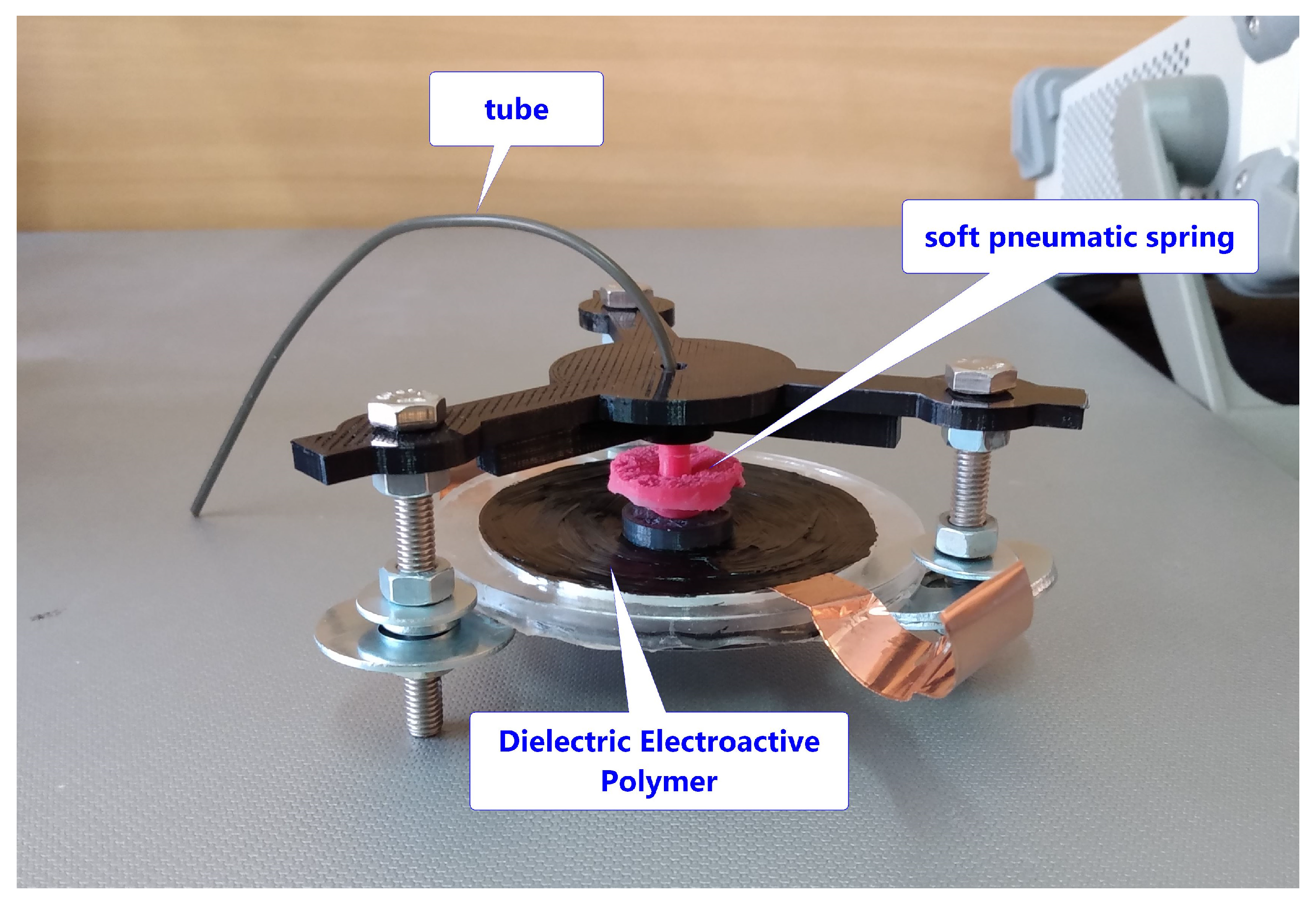
To construct the soft pneumatic spring, the silicon forms were built using a 3D printer. The construction process was divided into two steps. In the first one, the spring hat was molded. In the second one the basis was molded. During the second step, the hat was inserted into the basis. Hence, the two parts were permanently connected. To produce the soft spring, two-component molding silicon was used. The ratio between silicone and catalyst was 100:3 and the silicon Shore hardness was 25 A after solidification. The constructed spring is visible in Figure 5.
The pneumatic spring was connected to a pressure sensor. The connection tube is 17 c m long with a diameter of 1.5 m m , and hence the volume V t u b e is 300 m m 3 . The pressure was measured relative to air. The spring was mounted vertically and the force sensor compressed it as in the FEM simulation. The force signal was calibrated to zero at the beginning of the measurement when it did not touch the spring. The measurement was performed three times for different springs (built using the same procedure). The results of the simulation and measurement are visible in Figure 6. It can be seen that the results obtained from the modeling process agree with the measurements to a satisfactory level. Additionally, the measurement and simulations showed that the force pressure characteristics are linear.

3.2. DEAP Actuator

In the next step, the DEAP actuator was constructed and verified in a series of experiments. The DEAP actuator was assembled from a VHB membrane placed on the frame [21,26]. The membrane was pre-streched as in [2,12]. The pre-strech was performed by cutting a piece of the VHB membrane in a circular shape (radius of 4.5 c m ). The membrane segment was stretched into a circle frame with a radius of 10.5 c m . The membrane is elastic (with a Poisson ratio slightly below 0.5 ), and hence the volume of the membrane during stretching process is constant [2,27]. Hence, the thickness decreased with the ratio z p o s t = S p r e S p o s t z p r e , where S p r e and S p o s t are the area of the membrane before and after stretching, respectively, and z p r e and z p o s t is the thickness of the membrane before and after stretching, respectively. A summary of the DEAP membrane’s dimensions is presented in Table 1. The pneumatic bias was applied to DEAP membrane as is shown in Figure 7. The dimensions of the DEAP actuator are given in Table 1. The laboratory kit as shown in Figure 8 was used to perform measurements. The laboratory kit is equipped with a high voltage amplifier (TREK 10/10B-HS), a laser (Micro-Epsilon optoNCDT ILD1320–10 with 1 μ m accuracy) and a pressure sensor (Honeywell HSC dual port pressure sensor with 34.47 k Pa range). All devices were connected to an RT-DAC card that enables to control the input voltage and acquire the distance and pressure data.
In the first experiment, the piecewise constant voltage was applied with 11 different values of voltage ( 0, 3.5, 2, 6.75, 1.25, 2.1, 3.3, 4.3, 5.2, 6.1 and 0.2 kV). The response was measured three times with the same spring. During the experiment the pressure and distance were measured with a sampling period of 1 m s . Both signal were filtered with a Butterworth filter of order 2 and a cut-off frequency of 100 Hz . The steady state ratio R i was calculated between the pressure and distance:
R i = G p , i G d , i = Δ p s t e a d y , i Δ v i Δ d s t e a d y , i Δ v i = Δ p s t e a d y , i Δ d s t e a d y , i
where i is an index from 1 to 30 (the total number of trails and steps is 3 × 10 ), G p , i is a steady state gain between pressure and voltage, G d , i is a steady state gain between distance and voltage, Δ p s t e a d y , i is pressure at the steady state and Δ d s t e a d y , i is distance at the steady state. The symbol Δ shows that voltage, pressure and distance are relative to the value at the beginning of the step response. The mean value of R i from all trails and steps was equal to R = 29.5 mbar   mm 1 with a standard deviation of 2.6 . The three trials of the same single voltage step from 2 to 6.75 k V are presented in Figure 9 and the responses are shown in Figure 10. The response of the pressure is shown in Figure 10a,c,e and it is presented relative to the pressure value at the beginning of the step. It is visible that the value of the signal in the steady state is almost the same in all cases. The distances were multiplied by the distance to pressure ratio R and presented in Figure 10b,d,f (also relative to the distance value at the beginning of the step). The distance normalization was performed to better visualize the comparison between the pressure and distance signals. The transient was very fast at the beginning and had an additional slow relaxation process (with a time constant of about 3 s ). It is visible that pressure and normalized distance cover the steady state, but the transients are slightly different for both sensors. Furthermore, the pressure signal is definitely more noisy than the distance signal.
The frequency characteristics were measured to see the dynamic behavior of the DEAP actuator. The set of sinus input voltages was applied to the DEAP actuator with different frequencies f and amplitudes V a . The distance was multiplied by a static ratio R calculated for the step responses to better show the results. The frequency characteristics, which present the root mean square (RMS) of the signal, are shown in Figure 11 and Figure 12. The figures represent two independent experiments. The pressure signal is close to the distance for low frequencies (below 10 Hz ). One can also see a difference between the pressure and distance around the resonance frequency. It is visible that the resonance frequency is around 40 Hz for the pressure signal and around 30 Hz for the distance signal. Table 2 presents a resonance frequency comparison between different actuators in the literature. It is visible that mass-biased actuators have slightly lower values of resonance frequency (however, the influence of resonance frequency also has different factors like spring stiffness, hyper-elasticity characteristic of the membrane, mass and voltage amplitude).
In general, the presented novel type of bias allows to obtain the additional feedback signal. The pressure inside the chamber is easy to measure with a pressure sensor. The steady state characteristics show that pressure and distance are different with a constant ratio R. The described behavior is also visible in Figure 13, where the ratio R i was calculated between the RMS of the pressure and distance for sinus voltage excitation. There is difference between signals only at higher frequencies (around the resonance). In this case, the additional filter or observer must be designed to cover the both signals. This is planned by authors in future works.

4. Conclusions

In this paper a novel type of bias for DEAP actuators was presented. A soft pneumatic spring was used, coupled with a pressure sensor in the inner chamber. The modeling of a soft pneumatic spring in finite element model was described and the obtained results were compared with data measured in experiments. A comparison of force–pressure characteristics for the model and a prototype device showed a good agreement between the simulation and experimental validation. The pressure signal had a constant ratio with the distance for a steady state; however around the resonance frequency the pressure and distance differed significantly. The developed soft spring bias mechanism offers additional benefits that can be used in future DEAP actuator control systems. For instance, the pressure may be applied as an alternative feedback signal because it is strongly coupled with distance. Another idea for further research is to vary the initial pressure of the chamber. Relying on the force pressure characteristic that shows that load force causes a change to the chamber pressure, controlling the initial pressure of the chamber could allow to change the stiffness of the soft pneumatic spring.

5. Patents

The idea of the soft pneumatic bias for DEAP was initially described in the patent application J. Bernat, J. Kolota and D. Cieslak, “Elektroaktywny siłownik dielektryczny”, P.433764 (A1), Poland, 2020.

Author Contributions

Conceptualization, J.B. and J.K.; methodology, J.B. and J.K.; software, J.B.; validation, J.B. and J.K.; formal analysis, J.B. and J.K.; investigation, J.B. and J.K.; resources, J.B. and J.K.; data curation, J.B. and J.K.; writing—original draft preparation, J.B. and J.K.; writing—review and editing, J.B. and J.K.; visualization, J.B. and J.K.; supervision, J.B.; project administration, J.B.; funding acquisition, J.B. All authors have read and agreed to the published version of the manuscript.

Funding

This work was realized within the framework of project SONATA 13 No. 2017/26/D/ST7/ 00092 of the National Science Centre (Poland).

Institutional Review Board Statement

Not applicable.

Informed Consent Statement

Not applicable.

Data Availability Statement

Not applicable.

Conflicts of Interest

The authors declare no conflict of interest.

References

  1. Kim, K.; Tadokoro, S. Electroactive Polymers for Robotic Applications: Artificial Muscles and Sensors; Springe: London, UK, 2007; pp. 1–281. [Google Scholar] [CrossRef]
  2. Rizzello, G.; Naso, D.; York, A.; Seelecke, S. Modeling, Identification, and Control of a Dielectric Electro-Active Polymer Positioning System. IEEE Trans. Control Syst. Technol. 2015, 23, 632–643. [Google Scholar] [CrossRef]
  3. Mazzolai, B.; Mattoli, V. Robotics: Generation soft. Nature 2016, 536, 400–401. [Google Scholar] [CrossRef] [PubMed]
  4. Rosset, S.; Araromi, O.A.; Schlatter, S.; Shea, H. Fabrication Process of Silicone-based Dielectric Elastomer Actuators. J. Vis. Exp. 2016, 108, 1–13. [Google Scholar] [CrossRef] [PubMed] [Green Version]
  5. Loew, P.; Rizzello, G.; Seelecke, S. A novel biasing mechanism for circular out-of-plane dielectric actuators based on permanent magnets. Mechatronics 2018, 56, 48–57. [Google Scholar] [CrossRef]
  6. Hau, S.; Rizzello, G.; Seelecke, S. A novel dielectric elastomer membrane actuator concept for high-force applications. Extrem. Mech. Lett. 2018, 23, 24–28. [Google Scholar] [CrossRef]
  7. Cao, C.; Gao, X.; Conn, A. A Magnetically Coupled Dielectric Elastomer Pump for Soft Robotics. Adv. Mater. Technol. 2019, 4, 1900128. [Google Scholar] [CrossRef]
  8. Anderson, I.; Gisby, T.; McKay, T.; O’Brien, B.; Calius, E. Multi-functional dielectric elastomer artificial muscles for soft and smart machines. J. Appl. Phys. 2012, 112, 041101. [Google Scholar] [CrossRef]
  9. Zhang, Z.; Andersen, M. Electronics drivers for high voltage dielectric electro active polymer (DEAP) applications. In Proceedings of the Electroactive Polymer Actuators and Devices (EAPAD), San Diego, CA, USA, 9–12 March 2015; Volume 9430. [Google Scholar] [CrossRef] [Green Version]
  10. Schlatter, S.; Illenberger, P.; Rosset, S. Peta-pico-Voltron: An open-source high voltage power supply. HardwareX 2018, 4, e00039. [Google Scholar] [CrossRef]
  11. Sarban, R.; Lassen, B.; Willatzen, M. Dynamic Electromechanical Modeling of Dielectric Elastomer Actuators With Metallic Electrodes. IEEE/ASME Trans. Mechatron. 2012, 17, 960–967. [Google Scholar] [CrossRef]
  12. Bernat, J.; Kolota, J.; Rosset, S. Identification of a Nonlinear Dielectric Elastomer Actuator Based on the Harmonic Balance Method. IEEE/ASME Trans. Mechatron. 2020. [Google Scholar] [CrossRef]
  13. Gu, G.Y.; Gupta, U.; Zhu, J.; Zhu, L.M.; Zhu, X. Modeling of Viscoelastic Electromechanical Behavior in a Soft Dielectric Elastomer Actuator. IEEE Trans. Robot. 2017, 33, 1263–1271. [Google Scholar] [CrossRef]
  14. O’Brien, B.; McKay, T.; Calius, E.; Xie, S.; Anderson, I. Finite element modelling of dielectric elastomer minimum energy structures. Appl. Phys. A Mater. Sci. Process. 2009, 94, 507–514. [Google Scholar] [CrossRef]
  15. Loew, P.; Rizzello, G.; Simone, F.; Seelecke, S. Finite element simulation of plane strain dielectric elastomer membranes actuated by discretized electrodes. In Proceedings of the Electroactive Polymer Actuators and Devices (EAPAD) XXI, Denver, CO, USA, 4–7 March 2019; Volume 10966, pp. 88–96. [Google Scholar] [CrossRef]
  16. Cao, C.; Conn, A. Performance optimization of a conical dielectric elastomer actuator. Actuators 2018, 7, 32. [Google Scholar] [CrossRef] [Green Version]
  17. Hodgins, M.; York, A.; Seelecke, S. Experimental comparison of bias elements for out-of-plane DEAP actuator system. Smart Mater. Struct. 2013, 22, 094016. [Google Scholar] [CrossRef]
  18. Rizzello, G.; Naso, D.; Turchiano, B.; York, A.; Seelecke, S. LMI-based design of PI controllers for micropositioning dielectric electro-active polymer membranes. In Proceedings of the American Control Conference (ACC), Chicago, IL, USA, 1–3 July 2015; pp. 5509–5514. [Google Scholar] [CrossRef]
  19. Kolota, J. The FEM model of the pump made of dielectric electroactive polymer membrane. Appl. Sci. 2020, 10, 2283. [Google Scholar] [CrossRef] [Green Version]
  20. Kaal, W.; Herold, S. Electroactive polymer actuators in dynamic applications. IEEE/ASME Trans. Mechatron. 2011, 16, 24–32. [Google Scholar] [CrossRef]
  21. Bernat, J.; Kolota, J. Adaptive Observer for State and Load Force Estimation for Dielectric Electro-Active Polymer Actuator. In Proceedings of the 11th IFAC Symposium on Nonlinear Control Systems, Vienna, Austria, 4–6 September 2019; Volume 52, pp. 448–453. [Google Scholar]
  22. Cao, C.; Gao, X.; Burgess, S.; Conn, A. Power optimization of a conical dielectric elastomer actuator for resonant robotic systems. Extrem. Mech. Lett. 2020, 35, 100619. [Google Scholar] [CrossRef]
  23. Zhang, X.; Hu, J. Model-Free Adaptive Iterative Learning Control for A Pneumatic Muscle-Driven Robot. In Proceedings of the 2019 IEEE 3rd Information Technology, Networking, Electronic and Automation Control Conference (ITNEC), Chengdu, China, 15–17 March 2019; Volume 134, pp. 2246–2249. [Google Scholar] [CrossRef]
  24. Zhang, X.; Hu, J. Safety Enhancement of a Pneumatic Artificial Muscle Actuated Robotic Orthosis for Gait Rehabilitation. In Proceedings of the 2019 4th Asia-Pacific Conference on Intelligent Robot Systems (ACIRS), Nagoya, Japan, 13–15 July 2019; Volume 134, pp. 113–117. [Google Scholar] [CrossRef]
  25. Meththananda, I.; Parker, S.; Patel, M.; Braden, M. The relationship between Shore hardness of elastomeric dental materials and Young’s modulus. Dent. Mater. 2009, 25, 956–959. [Google Scholar] [CrossRef] [PubMed]
  26. Wissler, M.; Mazza, E. Mechanical behavior of an acrylic elastomer used in dielectric elastomer actuators. Sens. Actuators A Phys. 2007, 134, 494–504. [Google Scholar] [CrossRef]
  27. He, T.; Cui, L.; Chen, C.; Suo, Z. Nonlinear deformation analysis of a dielectric elastomer membrane–spring system. Smart Mater. Struct. 2010, 19, 085017. [Google Scholar] [CrossRef] [Green Version]
Figure 1. Example of biases in DEAP actuators: Membrane with spring bias (a); membrane with permanent magnet bias (b); membrane with mass bias (c).
Energies 14 01189 g001aEnergies 14 01189 g001b
Figure 2. The concept of soft pneumatic bias: Unbiased membrane (a); biased membrane with spring without voltage (b); biased membrane with spring with voltage (c).
Energies 14 01189 g002
Figure 3. The FEM mesh with fixed point and load force (the internal pressure inside the chamber is not visible) (a), and the dimensions of the soft pneumatic spring model alone (b).
Energies 14 01189 g003
Figure 4. The results of simulations for the FEM model of pneumatic spring without a DEAP membrane for two cases: without a load force (a) and with a load force (b).
Energies 14 01189 g004
Figure 5. The soft pneumatic spring molded from silicon.
Energies 14 01189 g005
Figure 6. Comparison of force–pressure characteristics for the FEM simulation and three different spring measurements.
Energies 14 01189 g006
Figure 7. The DEAP actuator with soft pneumatic spring bias.
Energies 14 01189 g007
Figure 8. The laboratory setup of the DEAP actuator measurement.
Energies 14 01189 g008
Figure 9. Example of the voltage transient applied to measure the step response of pressure and distance.
Energies 14 01189 g009
Figure 10. Comparison of distance and pressure of example step responses for voltages from 2 to 6.75 k V : Pressure (a,c,e) and normalized distance (b,d,f). Trial numbers: 1 (a,b), 2 (c,d), 3 (e,f).
Energies 14 01189 g010
Figure 11. Comparison of responses for sinus voltage excitation with different amplitudes for a large frequency range.
Energies 14 01189 g011
Figure 12. Comparison of responses for sinus voltage excitation with different amplitudes for frequencies around the resonance.
Energies 14 01189 g012
Figure 13. Comparison of the ratio R i for sinus voltage excitation with different amplitudes for low frequencies.
Energies 14 01189 g013
Table 1. Dimensions of the DEAP actuator.
NameValueUnit
Electrode width35 m m
Inner plate radius45 m m
Outer plate radius52 m m
Membrane initial thickness1 m m
Membrane final thickness0.18 m m
Table 2. Resonance frequency for DEAP actuators for various configurations [2,12,21].
DEAP Actuator TypeMassResonance Frequency
Mass biased (large size) [21]125 g 2.5 Hz
Mass biased (small size) [12]3 g 8.9 to 9.6 Hz
Spring biased (small size) [2] 7.1 g 20 to 45 Hz
Pneumatic spring biased (medium size)1 g 30 to 40 Hz
Publisher’s Note: MDPI stays neutral with regard to jurisdictional claims in published maps and institutional affiliations.

