1. Introduction
1.1. Summary
The general interior permanent magnet synchronous motor (IPMSM) uses NdFeB magnets to take advantage of the high airgap magnetic flux density. However, it has an adverse impact on the cost of the motor because there are fluctuations in the cost from limited sources of heavy rare-earths. Therefore, for a stable supply of permanent magnets, much development of a spoke-type permanent magnet synchronous motor (PMSM), which is a structure capable of concentrating magnetic flux by using a ferrite magnet having a low magnetic flux density, has been conducted [
1,
2]. The spoke-type PMSM concentrates the magnetic flux density and can replace the NdFeB magnet used in the extant PMSM with a ferrite magnet.
However, in general spoke-type PMSM, the portion of reluctance torque is low because the difference in inductance between the d-axis and the q-axis is not large. In order to further utilize this reluctance torque, a double-layer spoke-type shape that can maximize the difference in inductance between the d-axis and the q-axis can be used to increase the reluctance torque to improve motor performance [
3].
However, increasing the reluctance torque increases cogging torque, torque ripple, and total harmonic distortion (THD), which in turn leads to vibration and noise problems. Therefore, the double-layer spoke-type PMSM needs a design that can reduce cogging torque and THD [
4,
5,
6]. As a representative method, it can be solved by applying skew to the rotor [
7,
8,
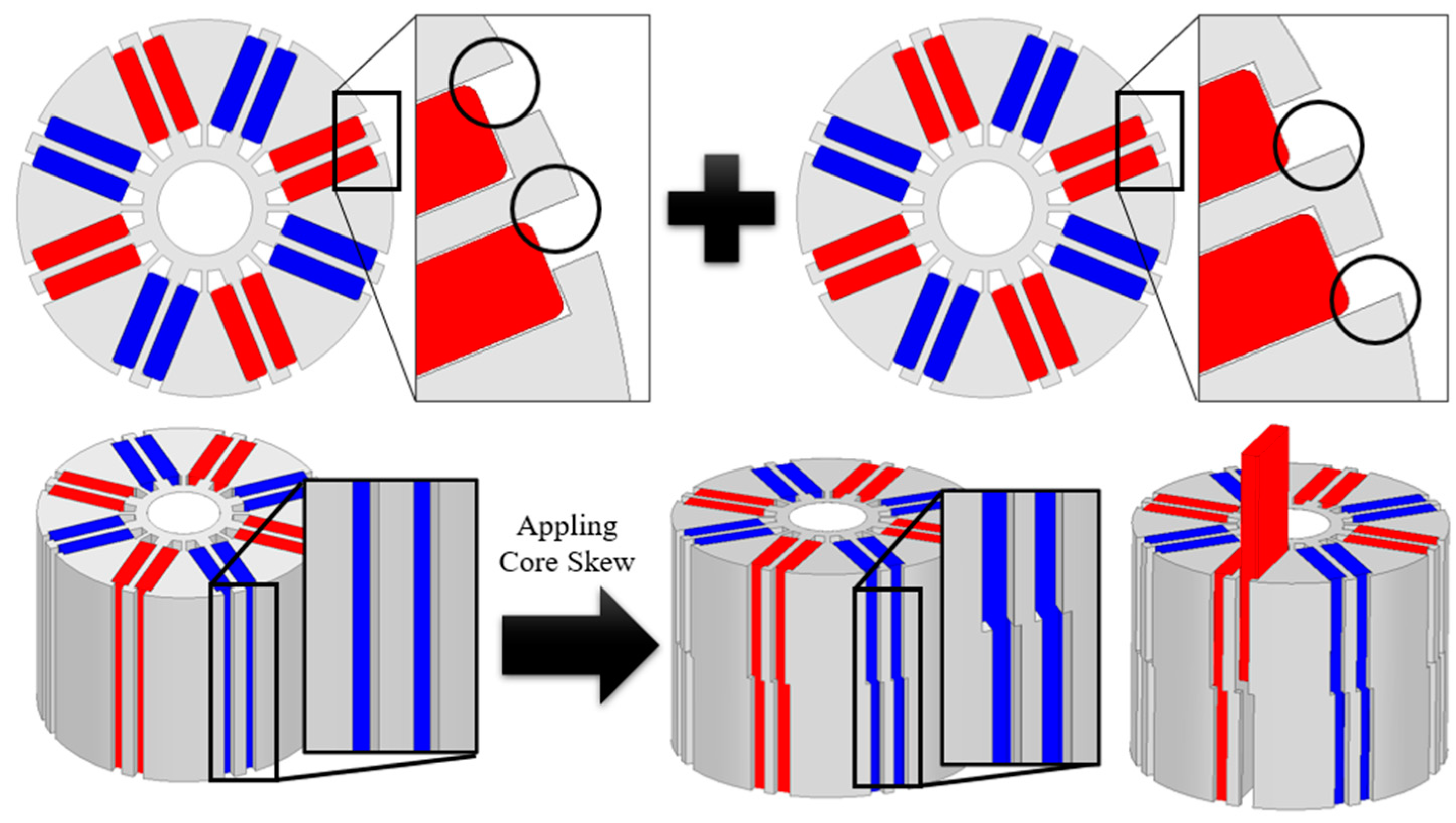
9], but the conventional method of applying skew is not a good method in terms of productivity, because it is difficult to manufacture as it divides the stages of the permanent magnet. To ameliorate the limitation, the shape of the rotor core is divided and cross-stacked into stack1 and stack2 so that the permanent magnet can be inserted in one shape as the conventional shape.
Therefore, the shape of the rotor core is divided into stack1 and stack2 so that the permanent magnet can be inserted in one shape as before and cross-stacked. The stack1 cuts the left part fixing the permanent magnet, and the stack2 cuts the right part fixing the permanent magnet to apply the same effect as skew. In this paper, this is expressed as a core skew, and through this core skew, the design to reduce cogging torque, torque ripple, and THD is conducted while considering productivity.
1.2. Conventional Model Specifications
In this paper, a study to reduce cogging torque, torque ripple, and THD for a double-layer spoke-type motor was conducted by selecting a washing machine motor having two operating areas: Low speed and high speed.
Washing machine motors are classified into two types: Belt-type motor and direct drive type. The direct drive-type motor is generally mounted on the rear of the drum-type washing machine to operate directly, and the belt-type motor is operated by connecting the belt to the shaft of the motor. The belt-type electric motor is used for general washing machine types, and the belt-type electric motor is also selected as the target model in this paper.
Figure 1 and
Table 1 show the shape and specifications of the conventional model.
The motor design of the washing machine must consider two modes of operation.
Figure 2 shows the torque-rotating speed characteristic graph of the conventional model, and the operating points of the washing load and dehydration load are indicated. As indicated by the operation point, it has two operation modes: Low speed (580 rpm), a washing operation mode; and high speed (15,660 rpm), a spin-dry operation mode. As the performance varies depending on the driving range, a design is required for two driving areas.
2. Governing Equation and Concept of Core Skew
2.1. Governing Equation
The contents of the basic theory are as follows. First, the cogging torque is generated by the force that tries to move in the direction where the path of the magnetic field is minimized, while the magnetic flux generated in the rotor permanent magnet crosses the airgap to the stator. In other words, it occurs as a result of the combined impact of the magnetic field of a permanent magnet located at the rotor and stator with variable magnetic conductivity depending on an angle of rotation [
10]. This can be represented by Equation (1) [
11,
12].
where
is the mechanical angle of the rotor and
is the magnetic energy of the apparatus. Magnetic energy means energy stored in a permanent magnet and is expressed as Equation (2).
where
is the permeability according to the material and
is the magnetic flux density. The cogging torque is expressed by the magnetic flux density generated in the permanent magnet and linkage to the teeth of the stator through the airgap.
In the electromagnetic field analysis based on finite element analysis (FEA), the torque equation is calculated using the Maxwell stress tensor method and is defined by Equations (3) and (4) [
13].
expressed in the above equation is the Maxwell stress tensor;
is the magnetic flux density;
and
are the components of the coordinate system;
is the Kronecker delta, which has a value of 1 when
and
are the same and 0 if they are different. As this paper deals with a spoke-type PMSM, it will be dealt with in a cylindrical coordinate system. The Maxwell stress tensor matrix in a cylindrical coordinate system is shown in Equation (5).
Thus, Equations (6)–(8) express the force using a cylindrical coordinate system. If the force is expressed in the tangential direction in the above equation, the torque will be expressed. This is equivalent to Equation (7).
Additionally, if Equation (7) is expressed as a line integral equation, it can be expressed as Equation (9).
The torque equation can be defined using the Maxwell stress tensor method. In this paper, FEA is performed using Ansoft’s Maxwell program and torque is calculated through the formula defined in Maxwell’s calculator.
2.2. Concept of Core Skew
The core skew represents the stacking of only cores of opposite shapes when stacking the rotor cores of the motor.
Figure 3 shows the flux lines of stack No. 1 and stack No. 2. Due to the shape of the rotor core, the phases of the airgap magnetic flux density of stack No. 1 and stack No. 2 are shifted, and when the two stacks are synthesized due to the phase of the shifted airgap magnetic flux density. As shown in
Figure 4, the cogging torque decreases.
Figure 5 shows the shape of applying the core skew to the conventional model by intersecting and stacking stack No. 1 and stack No. 2 of
Figure 3. In the case of stack No. 1 and stack No. 2 represented in
Figure 3, fixed bars that fix permanent magnets can be made into each shape using counter punching in the same mold. Therefore, it is possible to maintain extant production methods and equipment for production, and it can overcome the limitations of the extant skew method’s manufacturability by applying the core skew.
Through this core skew structure, research to reduce cogging torque, torque ripple, and THD is conducted. Most of the original skew research is conducted in 3D FEA, but as 3D FEA requires a lot of time, we first calculate the optimal model using 2D FEA and then proceed with 3D FEA according to the number of steps considering the 3D effect.
3. Geometric Variables and Their Effects from 2D FEA
3.1. Optimistic Design Based on Variables of Permanent Magnet Fixed Bar
Figure 6 and
Table 2 are settings for the first 2D FEA variables. First, the first core skew model is selected by deriving the optimal length through finite element analysis for the variable of the permanent magnet fixed bar. The variable range was set from 0 mm at the same point as the pocket opening of the permanent magnet of the existing model to 1.1 mm, which is the maximum pocket opening point at which the permanent magnet cannot be scattered.
Figure 7 represents 2D FEA results for the washing and dehydrating loads. When the importance weight of each cogging torque, no-load THD, and torque ripple during low- and high-speed operation was applied equally, all models with length of cutting 1 of 0.9 and length of cutting 2 of 0.8 were satisfied.
3.2. Optimistic Design Based on Variables of Tapering
From the first core skew model, the second core skew model is selected through finite element analysis of the position and angle of tapering at the end of the pole arc once again.
Figure 8 and
Table 3 are the settings for the second 2D FEA variables. The design variables were set as variables for the position and angle of the tapering when applying the outer tapering and when applying the inner tapering in contact with the permanent magnet. Similarly, variables for tapering were set in consideration of the scattering of permanent magnets.
Figure 9 shows the results of the second 2D FEA of the washing load and dehydrating load. Like the first 2D FEA, the importance weight of cogging torque, no-load THD, and torque ripple is equal, but in this second 2D FEA, the weight of satisfying the specifications of the conventional model is considered high priority.
In the case of the dehydrating load, which is a high-speed operation area, the magnetic flux density of the airgap through the tapering decreases, so the models that satisfy the torque compared to the conventional model are very limited. The model has a value of 0.8 mm for Tapering Pos_Out, 50° for Tapering Ang_Out, 0.2 mm for Tapering Pos_In, and 90° for Tapering Ang_In. The results of the first core skew model in the previous section and the second core skew model in this section are summarized in
Table 4.
In the case of the second core skew model compared to the conventional model, the cogging torque decreased 82%, the no-load THD decreased 1.12%p, and the torque ripple in the high-speed operation range decreased 61%p. However, it can be seen that the torque ripple in the low-speed operation range decreased compared to the first core skew model, but increased in the second core skew model.
3.3. Analysis of Result Data
In the previous section, the optimal models were calculated by applying each variable for the core skew model. For this, the components for each harmonic order were analyzed for cogging torque, torque ripple, and no-load THD.
Figure 10 and
Figure 11 show the analysis of cogging torque. In
Figure 10, it can be seen that the two stacks have cogging torques of different phases, and the peak value decreases compared to the conventional model during the synthesis of the two stacks.
Figure 11 shows the spectrum of cogging torque for each harmonic order. In the case of the conventional model, it can be seen that most of the components are composed of sixth harmonics. It can be seen that the sixth harmonic is greatly reduced in the two models selected in the previous section. In particular, in the case of the second model, tapering can be applied to increase the third harmonic and decrease the peak value of the sixth harmonic to reduce cogging torque.
Figure 12 and
Figure 13 show the torque ripple waveform and torque spectrum in the high-speed operation range, respectively. It can be seen that the dominant component of the torque ripple in the conventional model and the first core skew model, as in cogging torque, is the sixth harmonic. However, in the case of the second core skew model, it can be seen that the sixth harmonic is significantly reduced and the third harmonic is increased. It can be seen that by applying the tapering structure, the third harmonic is increased, the sixth harmonic is reduced, and the torque ripple is reduced.
Figure 14 shows the back electromotive force between lines at no load. The first model reduced the seventh harmonic and increased the fifth harmonic compared to the conventional model, but it was confirmed that the fifth harmonic decreased and the THD was reduced in the second model to which tapering was applied.
4. 3D FEA Based on Several Modeling Steps
Figure 15 shows that optimal models selected in 2D FEA are modeled from 2 to 8 steps. In the case of skew, as the 3D effect must be considered for each step, core skew also analyzes the 3D effect for each step through 3D FEA.
Table 5 represents results of the 3D FEA. It provides the fact that both the extant model and the core skew model all decreased cogging torque, torque ripple, and no-load THD compared to the 2D FEA results. As the 3D effect is considered, these factors decrease based on a circumstance that the airgap magnetic flux density decreases due to the generation of the leakage magnetic flux in the axial direction.
Compared to the conventional model, the core skew optimization model confirmed that by 3D FEA, the cogging torque decreased by 89%, the no-load THD by 1.15%p, and the torque ripple in the high-speed operation range by 62%p.
Figure 16 and
Figure 17 show the waveform of the cogging torque from 3D FEA steps. It is almost similar from 2 to 8 steps numerically, and it can be confirmed that it has decreased significantly compared to the conventional model. From some facts from
Figure 17, the high sixth harmonic of the conventional model can be confirmed, and the optimal models show that the sixth harmonic is greatly reduced, and the 12th harmonic is also reduced by more than 50%, indicating that the cogging torque is greatly reduced.
The torque ripple in the high-speed operation range is also significantly reduced. It can be checked from the amplitude of the waveform in
Figure 18. Although fundamental components slightly decrease in the high-speed region, which can be seen in
Figure 19, in the case of the sixth harmonic or twelfth harmonic, the core skew models are significantly reduced compared to the conventional model. Likewise, in the case of no-load THD, the core skew models have reduced harmonics of each order compared to the conventional model. It can be seen in
Figure 20.
5. Conclusions
In this paper, as the model selected as the target model was a belt-type washing machine motor, it was necessary to consider bidirectional operation instead of unidirectional operation during the washing load. Therefore, the core skew model was derived by synthesizing the symmetrical model by calculating the optimal model in 2D finite element analysis. First, the optimum model was selected by using the variable setting for the permanent magnet fixed bar, and then the optimum model was selected by applying a tapering to the end of the rotor. Finally, in order to consider the 3D effect of each number, the final model was selected through final verification through 3D finite element analysis.
Compared to the conventional model, it was confirmed that the components of each harmonic of the torque in the high-speed operation range in the core skew model were reduced, resulting in a significant reduction in cogging torque and torque ripple. No-load THD also confirmed a remarkable performance improvement through component analysis for each harmonic through FFT. In particular, the fifth and seventh harmonics, which are the main harmonic components of the back EMF, were reduced.
In addition, when the proposed structure is applied to an application of unidirectional operation, the cogging torque or torque ripple can be converged to almost zero with a skew shape in which the cogging torque and torque ripple of Stack No1 and Stack No2 are in opposite phases to each other. Finally, the proposed core skew principle can not only provide various core types, but is also expected to have a good influence on the future electric motor industry.
Author Contributions
Conceptualization, W.-H.K.; methodology, D.-W.N.; software, D.-W.N.; validation, D.-W.N.; formal analysis, D.-W.N.; investigation, D.-W.N.; resources, D.-W.N.; data curation, D.-W.N.; writing—original draft preparation, D.-W.N. and K.-B.L.; writing—review and editing, D.-W.N. and K.-B.L.; visualization, H.-J.P., M.-J.J. and S.-H.Y.; supervision, H.-K.J. All authors have read and agreed to the published version of the manuscript.
Funding
This work was supported by the Korea Evaluation Institute of Industrial Technology (KEIT) grant funded By the Ministry of Trade, Industry & Energy (MOTIE) (No.20011495), in part by the National Research Foundation of Korea (NRF) Grant funded by the Korean government (No. 2020R1A2C1013724) and in part by the Gachon University research fund of 2019 (No. GCU-2019-0770) (Corresponding author: Hyung-Kwan Jang).
Institutional Review Board Statement
Not applicable.
Informed Consent Statement
Not applicable.
Data Availability Statement
Not applicable.
Conflicts of Interest
The authors declare no conflict of interest.
References
- Dorrell, D.G.; Hsieh, M.-F.; Knight, A.M. Alternative rotor designs for high performance brushless permanent magnet machines for hybrid electric vehicles. IEEE Trans. Magn. 2012, 48, 835–838. [Google Scholar] [CrossRef]
- Rahman, M.M.; Kim, K.-T.; Hur, J. Design and optimization of neodymium-free SPOKE-type motor with segmented wing-shaped PM. IEEE Trans. Magn. 2014, 50, 865–868. [Google Scholar] [CrossRef]
- Kim, S.I.; Park, S.; Park, T.; Cho, J.; Kim, W.; Lim, S. Investigation and experimental verification of a novel spoke-type ferrite-magnet motor for electric-vehicle traction drive applications. IEEE Trans. Ind. Electron. 2014, 61, 5763–5770. [Google Scholar]
- Kim, K.-C. A novel method for minimization of cogging torque and torque ripple for interior permanent magnet synchronous motor. IEEE Trans. Magn. 2014, 50, 793–796. [Google Scholar] [CrossRef]
- Bianchini, C.; Immovilli, F.; Lorenzani, E.; Bellini, A.; Davoli, M. Review of design solutions for internal permanent-magnet machines cogging torque reduction. IEEE Trans. Magn. 2012, 48, 2685–2693. [Google Scholar] [CrossRef]
- Zhu, Z.Q.; Liu, Y.; Howe, D. Minimizing the influence of cogging torque on vibration of PM brushless machines by direct torque control. IEEE Trans. Magn. 2006, 42, 3512–3514. [Google Scholar] [CrossRef]
- Jahns, T.M.; Soong, W.L. Pulsating torque minimization techniques for permanent magnet AC motor drives—A review. IEEE Trans. Ind. Appl. 1996, 43, 321–330. [Google Scholar] [CrossRef]
- Zhu, Z.Q.; Howe, D. Influence of design parameters on cogging torque in permanent magnet machines. IEEE Trans. Energy Convers. 2000, 15, 407–412. [Google Scholar] [CrossRef] [Green Version]
- Zhu, L.; Jiang, S.Z.; Zhu, Z.Q.; Chan, C.C. Analytical methods for minimizing cogging torque in permanent-magnet machines. IEEE Trans. Magn. 2009, 45, 2023–2031. [Google Scholar] [CrossRef]
- Goryca, Z.; Różowicz, S.; Różowicz, A.; Pakosz, A.; Leśko, M.; Wachta, H. Impact of Selected Methods of Cogging Torque Reduction in Multipolar Permanent-Magnet Machines. Energies 2020, 13, 6108. [Google Scholar] [CrossRef]
- Zhao, W.; Lipo, T.A.; Kwon, B.I. Torque pulsation minimization in spoke-type interior permanent magnet motors with skewing and sinusoidal permanent magnet configurations. IEEE Trans. Magn. 2015, 51, 1–4. [Google Scholar]
- Coulomb, J.L.; Meunier, G. Finite element implementation of virtual work principle for magnetic or electric force and torque computation. IEEE Trans. Magn. 1984, 20, 1894–1896. [Google Scholar] [CrossRef]
- Meessen, K.J.; Paulides, J.J.H.; Lomonova, E.A. Force calculations in 3-D cylindrical structures using fourier analysis and the maxwell stress tensor. IEEE Trans. Magn. 2013, 49, 536–545. [Google Scholar] [CrossRef]
Figure 1.
Conventional model. (a) Stator and rotor; (b) rotor structure.
Figure 1.
Conventional model. (a) Stator and rotor; (b) rotor structure.
Figure 2.
Operating point of washing load and dehydration load of the conventional model.
Figure 2.
Operating point of washing load and dehydration load of the conventional model.
Figure 3.
Magnetic flux line. (a) Stack No.1; (b) Stack No.2.
Figure 3.
Magnetic flux line. (a) Stack No.1; (b) Stack No.2.
Figure 4.
Example of reduction of cogging torque through core skew.
Figure 4.
Example of reduction of cogging torque through core skew.
Figure 5.
Concept diagram of core skew.
Figure 5.
Concept diagram of core skew.
Figure 6.
Variable of permanent magnet fixed bar.
Figure 6.
Variable of permanent magnet fixed bar.
Figure 7.
Results of the first 2D finite element analysis at washing and dehydrating load.
Figure 7.
Results of the first 2D finite element analysis at washing and dehydrating load.
Figure 8.
Variable of tapering.
Figure 8.
Variable of tapering.
Figure 9.
Results of the second 2D finite element analysis at washing and dehydrating load.
Figure 9.
Results of the second 2D finite element analysis at washing and dehydrating load.
Figure 10.
Cogging torque comparison. (a) First core skew model cogging torque; (b) second core skew model cogging torque; (c) comparison between the conventional model and the first and second core skew models.
Figure 10.
Cogging torque comparison. (a) First core skew model cogging torque; (b) second core skew model cogging torque; (c) comparison between the conventional model and the first and second core skew models.
Figure 11.
Spectra of cogging torque for each model.
Figure 11.
Spectra of cogging torque for each model.
Figure 12.
15,660 rpm torque waveform comparison.
Figure 12.
15,660 rpm torque waveform comparison.
Figure 13.
15,660 rpm torque spectra.
Figure 13.
15,660 rpm torque spectra.
Figure 14.
15,660 rpm no-load line-induced voltage spectra.
Figure 14.
15,660 rpm no-load line-induced voltage spectra.
Figure 15.
3D rotor model. (a) 2-step model; (b) 4-step model; (c) 6-step model; (d) 8-step model.
Figure 15.
3D rotor model. (a) 2-step model; (b) 4-step model; (c) 6-step model; (d) 8-step model.
Figure 16.
Cogging torque waveform comparison according to the number of steps.
Figure 16.
Cogging torque waveform comparison according to the number of steps.
Figure 17.
Spectra of cogging torque according to the number of steps.
Figure 17.
Spectra of cogging torque according to the number of steps.
Figure 18.
15,660 rpm torque waveform comparison according to the number of steps.
Figure 18.
15,660 rpm torque waveform comparison according to the number of steps.
Figure 19.
15,660 rpm torque spectra according to the number of steps.
Figure 19.
15,660 rpm torque spectra according to the number of steps.
Figure 20.
15,660 rpm line-induced voltage spectra according to the number of steps.
Figure 20.
15,660 rpm line-induced voltage spectra according to the number of steps.
Table 1.
Specifications of conventional model.
Table 1.
Specifications of conventional model.
| Parameter | Value | Unit |
|---|
| Number of poles | 8 | - |
| Number of slots | 12 | - |
| Cogging torque pk 2 pk | 97.27 | mNm |
| No-load THD | 3.2 | % |
| DC link voltage | 280 | V |
580 rpm
Washing
load | Torque | 1.35 | Nm |
| Current | 1.84 | Arms |
| Current phase angle | 14 | deg |
| Torque ripple | 7.6 | % |
| Copper Loss | 29.25 | W |
| Core Loss | 1.6 | W |
| Efficiency | 72.75 | % |
15,660 rpm
Dehydration
load | Torque | 0.2 | Nm |
| Current | 2.16 | Arms |
| Current phase angle | 83.4 | deg |
| Torque ripple | 127.37 | % |
| Copper Loss | 52.35 | W |
| Core Loss | 38.92 | W |
| Efficiency | 79.17 | % |
Table 2.
Variable setting of permanent magnet fixed bar.
Table 2.
Variable setting of permanent magnet fixed bar.
| Parameter | Range | Step | Unit |
|---|
| Length of Cutting1 | 0–1.1 | 0.1 | mm |
| Length of Cutting2 | 0–1.1 | 0.1 | mm |
Table 3.
Variable setting of tapering.
Table 3.
Variable setting of tapering.
| Parameter | Range | Step | Unit |
|---|
| Tapering Pos_Out | 0–0.8 | 0.1 | mm |
| Tapering Ang_Out | 0–90 | 10 | deg |
| Tapering Pos_In | 0–0.2 | 0.1 | mm |
| Tapering Ang_In | 0–90 | 10 | deg |
Table 4.
Variable set.
| Parameter | Conventional Model | Core Skew
1st Model | Core Skew
2nd Model | Unit |
|---|
| Cogging torque pk 2 pk | 97.27 | 44.54 | 17.56 | mNm |
| No-load THD | 3.2 | 2.93 | 2.08 | % |
| 580 rpm | Torque | 1.35 | 1.38 | 1.37 | Nm |
| Torque ripple | 7.6 | 7.02 | 8.35 | % |
| 15,660 rpm | Torque | 0.2 | 0.2 | 0.2 | Nm |
| Torque ripple | 127.37 | 97.27 | 66.21 | % |
Table 5.
Variable set.
| Parameter | Conventional Model | 2-Step Model | 4-Step Model | 6-Step Model | 8-Step Model | Unit |
|---|
| Cogging torque pk 2 pk | 78.61 | 8.46 | 8.17 | 8.34 | 8.62 | mNm |
| No-load THD | 2.37 | 1.22 | 1.25 | 1.27 | 1.29 | % |
| 580 rpm | Torque | 1.33 | 1.34 | 1.34 | 1.34 | 1.34 | Nm |
| Torque ripple | 4.29 | 9.04 | 8.94 | 8.81 | 8.67 | % |
| 15,660 rpm | Torque | 0.2 | 0.19 | 0.19 | 0.19 | 0.19 | Nm |
| Torque ripple | 114.6 | 52.60 | 53.78 | 54.50 | 55.38 | % |
| Publisher’s Note: MDPI stays neutral with regard to jurisdictional claims in published maps and institutional affiliations. |
© 2021 by the authors. Licensee MDPI, Basel, Switzerland. This article is an open access article distributed under the terms and conditions of the Creative Commons Attribution (CC BY) license (http://creativecommons.org/licenses/by/4.0/).


 ,
, 


