Article

Augmentation of Heat Transfer in a Circular Channel with Inline and Staggered Baffles

by
Muneerah Al Nuwairan
1 and
Basma Souayeh
2,3,*
1
Department of Mathematics and Statistics, College of Science, King Faisal University, P.O. Box 400, Al-Ahsa 31982, Saudi Arabia
2
Department of Physics, College of Science, King Faisal University, P.O. Box 400, Al-Ahsa 31982, Saudi Arabia
3
Laboratory of Fluid Mechanics, Physics Department, Faculty of Sciences of Tunis, University of Tunis El Manar, Tunis 2092, Tunisia
*
Author to whom correspondence should be addressed.
Energies 2021, 14(24), 8593; https://doi.org/10.3390/en14248593
Submission received: 22 November 2021 / Revised: 15 December 2021 / Accepted: 16 December 2021 / Published: 20 December 2021

Abstract

:
This numerical investigation presents the effects of the position of baffles in the shape of a circle’s segment placed inside a circular channel to improve the thermal and flow performance of a solar air heater. Three different baffles’ positions with Reynolds number varying between 10,000 to 50,000 were investigated computationally. The k-omega SST model was used for solving the governing equations. Air was taken as the working fluid. Three pitch ratios (Y = 3, 4, and 5) were considered, while the height of the baffles remained fixed. The result showed an enhancement in Nusselt number, friction factor, j-factor, and thermal performance factor. Staggered exit-length baffles showed maximum enhancement in heat transfer and pressure drop, while inline inlet-length baffles showed the least enhancement. For a pitch ratio of Y = 3.0, the enhancement in all parameters was the highest, while for Y = 5.0, the enhancement in all parameters was the least. The highest thermal performance factor of 1.6 was found for SEL at Y = 3.0.

1. Introduction

Many engineering applications, such as chemicals production, refrigeration, car production, and solar air heaters, require a high-performance heat exchanger (HE) to efficiently utilize energy sources, so to achieve advantageous heat exchange with a limited cost [1,2,3,4,5,6]. Thus, several technologies have been studied in the last years to increase the rate of heat transfer (HT) from a tube. The main strategies to increase the performance of HEs involve increasing the surface area of the tube wall between the working fluids and reducing the resistance of the flow across the HE. Thermal performance augmentation of HEs is a hot topic for evaluate working in this area, and the main goal is to find the best output from an HE for the same quantity of work in order to save money and energy. Two specific types of techniques are used evaluate the thermal performance of heat exchangers and other related devices—Active and Passive methods of heat transfer enhancement [7]. Active techniques require external power sources i.e., a magnetic field, an electric field, ultrasonic waves, corona wind, etc. The cost of the necessary equipment is very high, and its operation requires highly skilled workers. In contrast, the passive techniques of heat transfer enhancement (HTE) are easy to operate, have a low cost, and allow an appreciable performance enhancement [8,9,10,11,12]. Therefore, most researchers are investigating passive heat transfer enhancement. Several THE designs are used to increase the performance of the system. Amongst various passive methods of HTE, the use of ribs and baffles is constantly evolving due to the higher heat transfer coefficient (HTC) and lower frictional losses. The geometrical parameters of the ribs/baffles play a very important role in enhancing the HT and the performance of the system [13,14]. Swirl generator geometries deliver a high HT rate, but at the same time, the increase in pumping power cannot be ignored. An enormous care has been dedicated to dropping the pumping power to achieve a performance above the unity.
Several investigations have been carried out in the past on the importance of geometrical parameters for the thermohydraulic properties of the heat exchanger duct. Bhattacharyya et al. [15] used perforated angular cut baffles fitted in a circular channel, with air as the working medium and showed that Reynolds number (Re) varied between 10,000 to 52,000. The results obtained from this investigation showed intensification in heat transfer and friction. However, the thermal performance factor in all cases remained above the unity. Sriromreun et al. [16] performed a computational and experimental investigation inside a rectangular channel fitted with z-shaped baffles to evaluate the thermal and flow performance. Air was used as the working fluid, with Re varying from 4400 to 20,400. In the same operating state, the Nusselt number (Nu), friction factor (f), and thermal performance enhancement factor for in-phase 45° Z-baffles were shown to be much greater than those for out-phase 45° Z-baffles. Karwa et al. [17] studied the influence of perforated baffles on the thermal and flow performance inside a rectangular channel and compared the results with those obtained using plain baffles. The results showed enhancement of heat transfer, while the friction factor was reduced compared with that using plain baffles. Promvonge and Kwankaomeng [18] carried out a numerical investigation with V-shaped baffles having an attack angle of 45° and periodic laminar flow at different heights in a channel and reported an enhancement of heat transfer as well as of the friction factor as the baffles height increased. Chamoli and Thakur [19] performed an analytical investigation with perforated V-shapes baffles for evaluating the exergetic efficiency of a solar air heater and reported an enhancement in thermal efficiency. Rashidi et al. [20] numerically investigated the combined influence of a nanofluid and transverse twisted baffles on the thermal and flow performance. Menni et al. [21] numerically investigated the thermal and flow performance of a solar duct fitted with V-baffles and reported an enhancement of heat transfer as well as of the friction factor. Samruaisin et al. [22] reported the influence of twisted tape with transverse twisted baffles on thermal and flow performance. The findings revealed that twisted tapes with transverse twisted baffles had greater heat transfer rates, friction factors, and thermal enhancement factor than twisted tapes without them. Yu et al. [23] investigated the influence of triangular baffles on the thermal performance of an air-type PVT collector and reported a 3.6–3.9 °C increase in the outlet temperature, while the thermal performance increased by 31%. Bensaci et al. [24] carried out a numerical and experimental assessment to investigate the influence of the location of baffles inside a solar air heater for heat transfer enhancement. It was revealed that not only the size and the geometry but also the position of the baffles is an important parameter for achieving maximum heat transfer enhancement. For the purpose of enhancing the thermal performance, Reddy and Satyanarayana [25] ran a 3-D CFD simulation of a novel solar receiver. Different porous inserts, such as circular, trapezoidal, and square, were included in the receiver. Sari et al. [26] carried out a numerical assessment for baffles and a vortex generator in a solar air collector and validated the results with experiments. It was reported that the use of a vortex generator and baffles enhanced the thermal and flow performance significantly. Yaningsih et al. [27] studied single-phase flow heat transfer experimentally to calculate the thermal performance of louvered swirl generator inserts. In the study, it was reported that the HT increased with the increase of the Reynolds number, and the strip allowed increases in HT up to 77.02% compared to a smooth tube. The strip’s slant angle plays an important role in enhancing HT, and a large slant angle is also helpful. Wijayanta et al. [28] investigated numerically HTE by using a special type of twisted tape. The proposed novel geometry showed promising results in terms of HT and performance of the system. HT increased with the rise of the attack angle, and the thermal performance was greater than the unity in all tested cases. Wijayanta et al. [29] reported numerically the augmentation of HT by using twisted tape with high Reynolds number. In the study, the length ratio played an important role, and the thermal performance was almost greater than the unity in all tested cases.
After reviewing several articles related to heat transfer enhancement using baffles, the authors of the present investigation found that baffles are very effective tools in heat transfer enhancement. Short-length vortex generator inserts [29] are more beneficial than other enhancing devices because of a remarkably better pressure loss; therefore, the geometrical parameters of the baffles play a significant role in determining the thermal performance of heat exchangers. Most of the previous studies used long baffle and reported a high pressure disadvantage. Therefore, in this numerical investigation, novel effective short-length baffles in the shape of circle’s segment were used as turbulence promoters. As compared with the existing literature, the current work describes for the first time various effective short lengths, baffle heights, baffle pitches, and orientations of the turbulator. The new design of the baffles promoted shearing of the boundary layer and allowed a secondary flow in the flow field, which resulted in a higher heat transfer rate. ANSYS Fluent 19.0 was used for the numerical simulations. Air, with Reynolds number between 10,000–50,000, was used as the working medium.

2. Physical Model and Governing Equations

Figure 1 shows the schematic of the fluid domain used for the numerical simulations. In total, 15 baffles were positioned, separately, at the inlet, middle, and end of the circular channel to investigate the influence of baffles’ positioning in the channel. The influence of inline as well as staggered baffles in the circular channel was examined. Three pitches (P) of 60, 80, and 100 mm were considered. The length of the circular channel was 2000 mm, and the diameter was 20 mm. A itch ratio Y = P/D = 3, 4, and 5 was used throughout the investigation to non-dimensionalize the parameter. For designing the model, the commercially available software SolidWorks was employed. The channel was uniformly heated with a heat flux of 2 kW/m2. The velocity inlet on the left side of the channel was based on a Reynolds number between 10,000 and 50,000, while the exit was the pressure outlet. The entering flow was turbulent, with inlet turbulent intensity of 5% and an ambient temperature of Tin = 300 K. No slip condition was considered on the channel and rib surfaces.
The following assumptions were made:
The flow was steady, three-dimensional, and developing.
All simulations were performed for a fixed value of heat flux (2 kW/m2). The Reynolds number varied between 10,000 to 50,000.
Air was used as the working medium, and the flow was single-phase.
The thermal conductivity of the baffles, and therefore their heat absorption, were neglected.
In the simulations performed, the commercially available software ANSYS Fluent 19.0 was used to analyze the fluid flow and heat transfer of the 3D computational domain, using the Finite Volume Method. The incompressible steady flow of a Newtonian fluid was investigated. The material’s properties were assumed to be constant. The effect of buoyancy, viscous heating, and radiation were neglected. A steady-state RANS approach was utilized for turbulence modelling to reduce the computational efforts. Consequently, with the RANS turbulence model, the two-equation SST of Menter [30] was employed. The governing equations are summarized below.
Continuity equation:
u i x i = 0
Navier–Stokes equations:
ρ u i u j x i = P x i + x i μ + μ t u r b u i x i
Energy equation:
u i Θ x i = x i ( α + ν t u r b P r t u r b ) Θ x i
Equations of the turbulence model:
ρ u i κ x i = γ P κ β 1 ρ κ ω + x i ( μ + μ t u r b σ κ ) κ x i
where
μ t u r b = a ρ κ m a x ( a ω , S F 2 )
i = 1,2,3, j = 1,2,3

3. Meshing and Grid Independence Study

Figure 2 shows the sample grid used in the presented simulations. The precision and stability of numerical computations in computational numerical domains depend on the use of high-quality grids. Three distinct grids were evaluated in the grid independence investigation, and the average Nu and f are reported in Table 1. As a result, the grid with 1,374,386 cells was used for all simulations to reduce the simulation time.

4. Data Reduction

The following parameters were used in the present investigation:
Diameter (D), mm: 20 mm
Length (L), mm: 2000 mm
Pitch Ratio (Y) = P/D: 3, 4, and 5
Baffle height (e), mm: 5 mm (constant throughout the simulation)
Baffle effective length (Lw), mm: 150 mm (constant throughout the simulation for inlet portion, middle portion, and exit portion)
Baffle thickness (t), mm: 2 mm (constant throughout the simulation)
The following sets of equations were utilized for the calculation:
Heat transferred to the air was given by:
Q A i r = m × C p T O u t T i n  
Total heat loss was given by:
Q L o s s = Q H e a t e r Q A i r
Heat flux was given by:
q = Q A i r A S u r = Q A i r π D L
Reynolds number (Re) was calculated using the following relation [31]:
R e = 4 × m π D µ
For the determination of the local temperature at various positions:
T ( x ) = T i n + T o u t T i n x L
For the calculation of the bulk temperature:
T b = T i n + T o u t 2
The local convective heat transfer coefficient (h) was calculated with:
h x = q T s x T x
where T s x is the mean surface temperature at position x, and T x is the mean temperature of the working fluid at position x.
For calculating the average heat transfer coefficient [32]:
h = q T s T b
where T s   is the surface temperature.
The Nusselt number (Nu) was given by [33]:
N u = h D k
The heat transfer can also be obtained using the Colburn j-factor, simply called j-factor, by [34]:
j = N u R e P r 1 3
For friction factor calculation, the formula used is [35,36]:
f = Δ p L D 1 2 ρ V 2
For calculating the thermal performance factor, the following formula can be used [37,38,39,40,41]:
η = N u / N u 0 f / f 0 0.33
where the subscript 0 denotes the plain duct

5. Results and Discussion

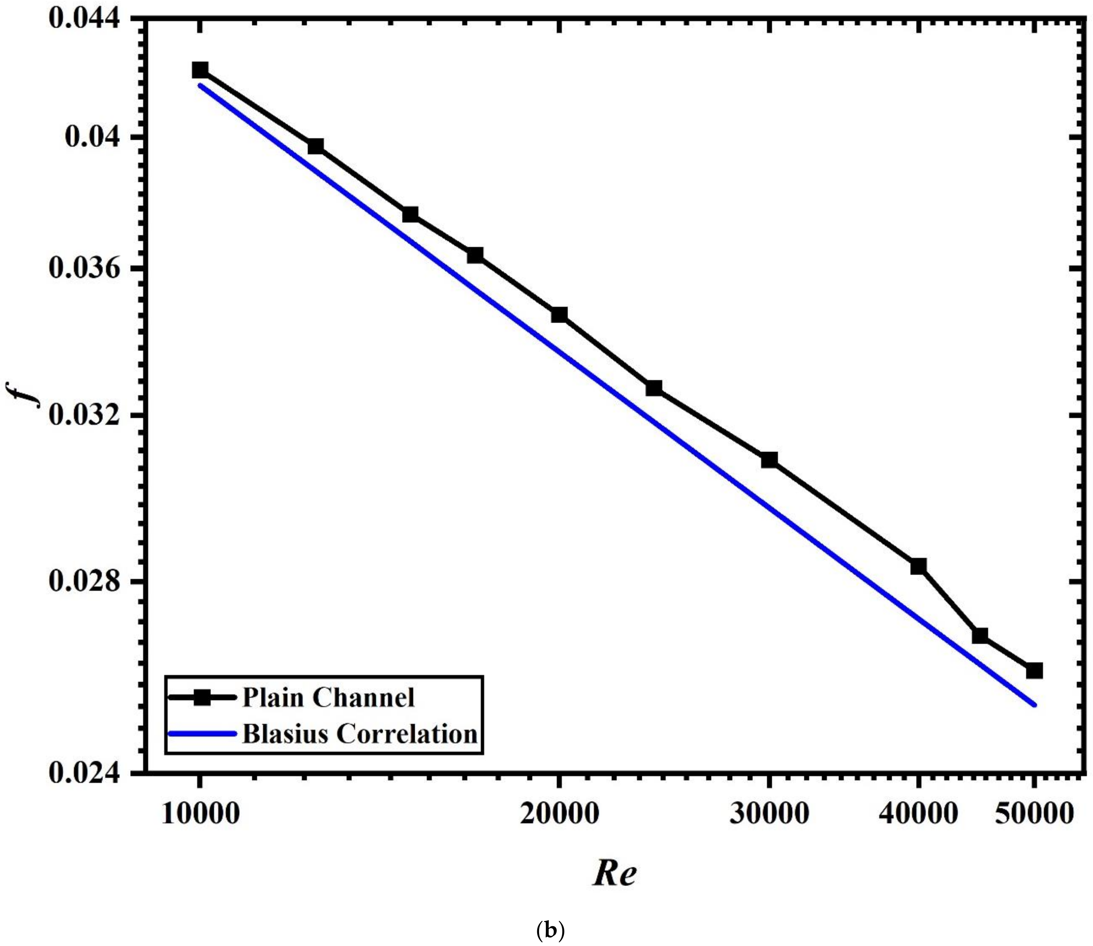
5.1. Validation of Nu and f
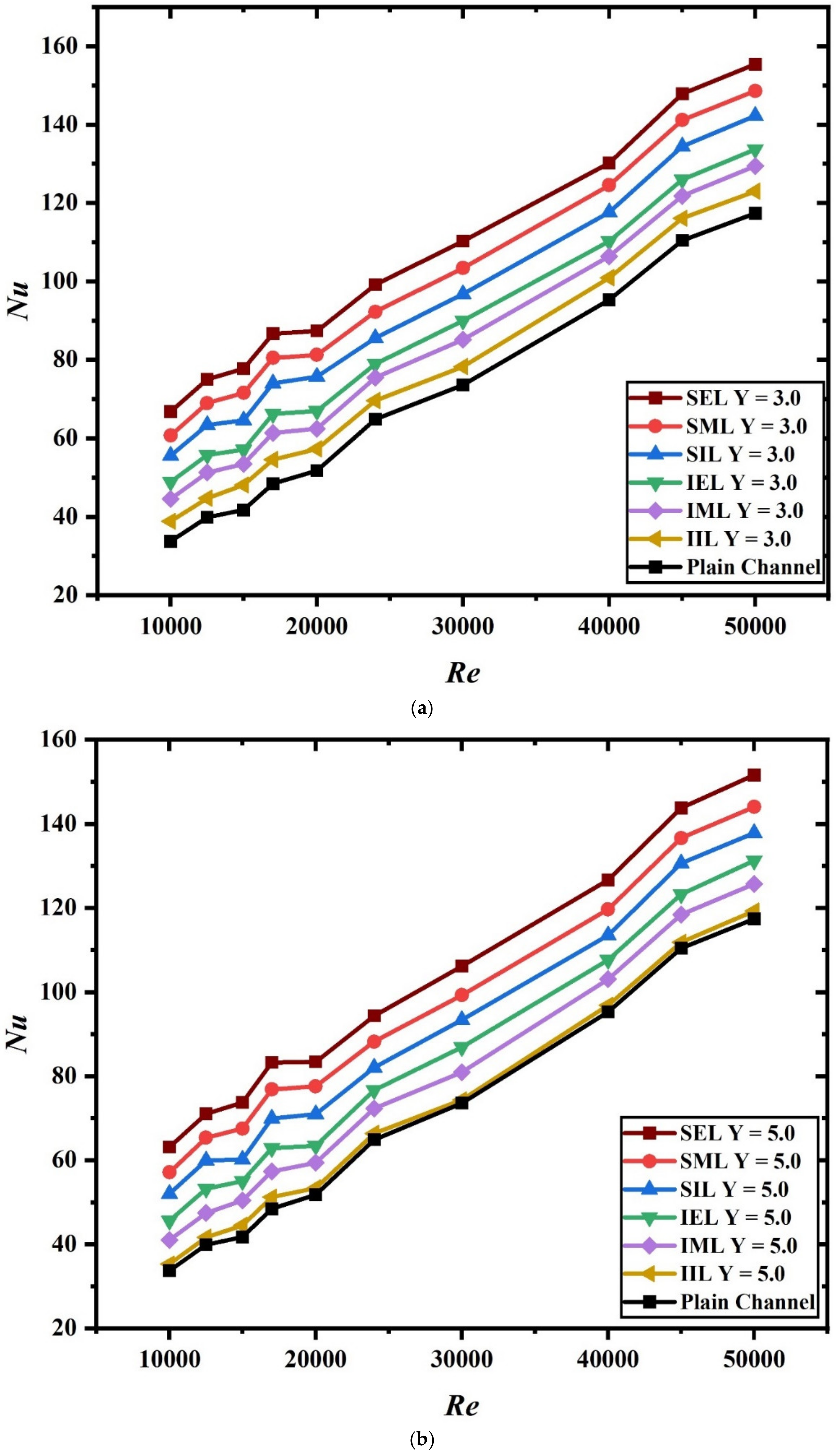
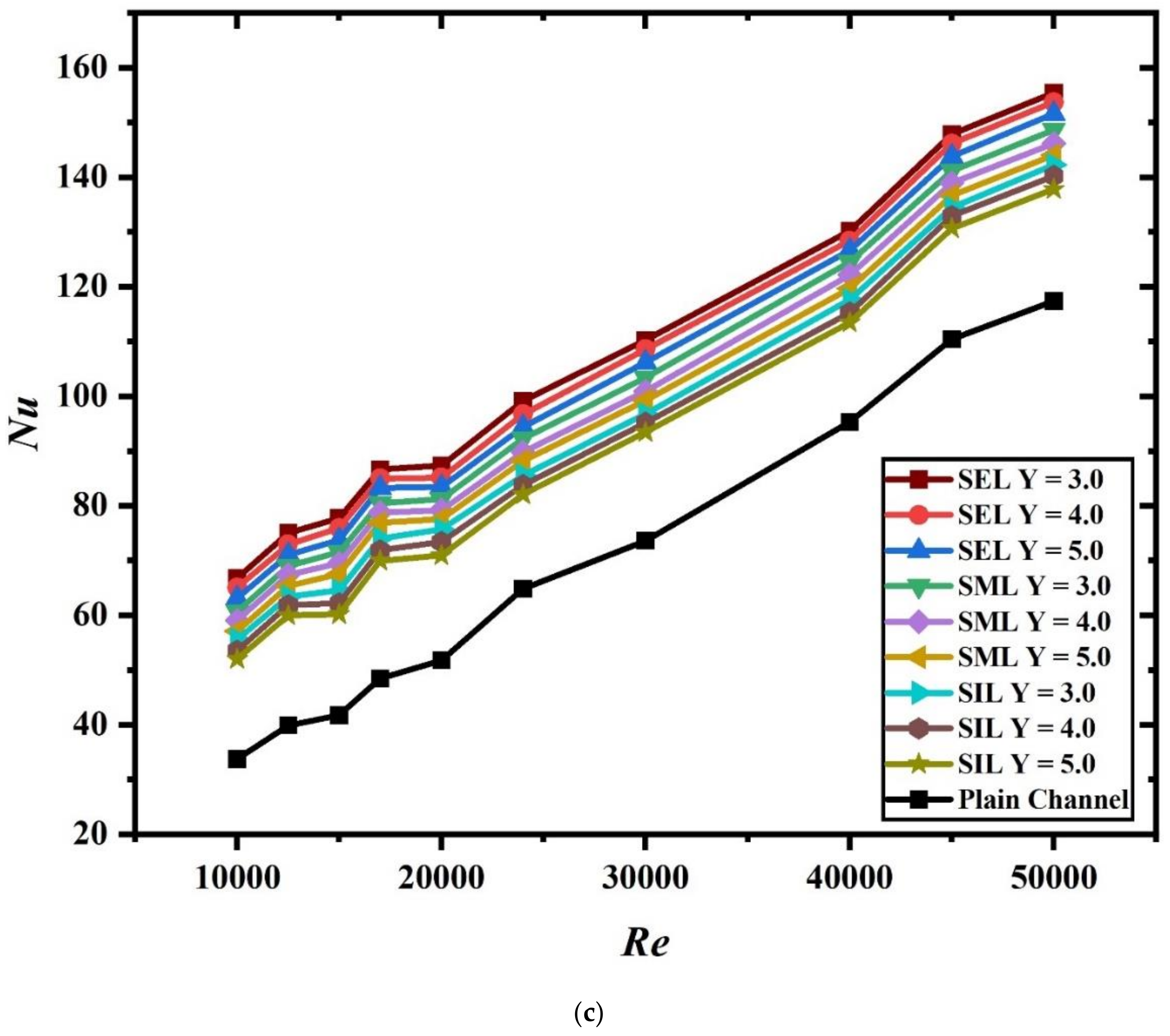
The current numerical findings were compared using the Dittus–Boelter correlation [42] and the Blasius correlation [43] for Nu and f, respectively, to determine the accuracy of the numerical approach. The results are presented Figure 3a,b The deviation in Nusselt number value was less than 1%, while for the friction factor, the deviation was 2.7%. This indicated that the present simulation investigation showed a 95% confidence level and was in very good agreement with well-established correlations.

5.2. Nusselt Number

Figure 4a–c shows the variation of Nu with Re for pitch ratios of 3.0 and 5.0 and staggered baffles, respectively. As expected, the plain channel showed the lowest Nusselt number values. In the case of a channel with inline baffles, the inline exit-length baffles (IEL) showed the highest enhancement in the Nusselt number, while inline inlet-length baffles (IIL) showed the least enhancement for all values of pitch ratio when compared with the plain channel. For staggered baffles, staggered exit-length baffles (SEL) showed the highest enhancement in the Nusselt number, while staggered inlet-length baffles (SIL) showed the least enhancement when compared with the plain channel. For only staggered baffles, staggered exit-length baffles (SEL) having a pitch ratio of 3.0 showed the highest enhancement, while SEL having a pitch ratio of 5.0 showed the least augmentation in Nusselt number (refer Figure 4a,b). A similar trend was observed for staggered middle-length (SML) and staggered inlet-length (SIL) baffles. Moreover, SEL baffles showed the highest Nusselt number, followed by SML and SIL baffles (refer Figure 4c). It is also worth noticing for all the cases of inline as well as staggered baffles that an increase in the Re resulted in a higher value of Nu. In the absence of baffles, the flow temperature rose steadily and uniformly along the channel, as expected. In comparison to a smooth duct, increasing the Re values reduced the thickness of the laminar sub-layers (smooth). The presence of baffles in the flow field resulted in an intense mixing of fluid, which caused the rise in Nu. In the case of staggered baffles, the mixing intensity further increased, which resulted in higher Nu and heat transfer rate. It is evident from the results shown in Figure 4a–c, that the insertion of baffles had a favorable effect on heat transfer enhancement.

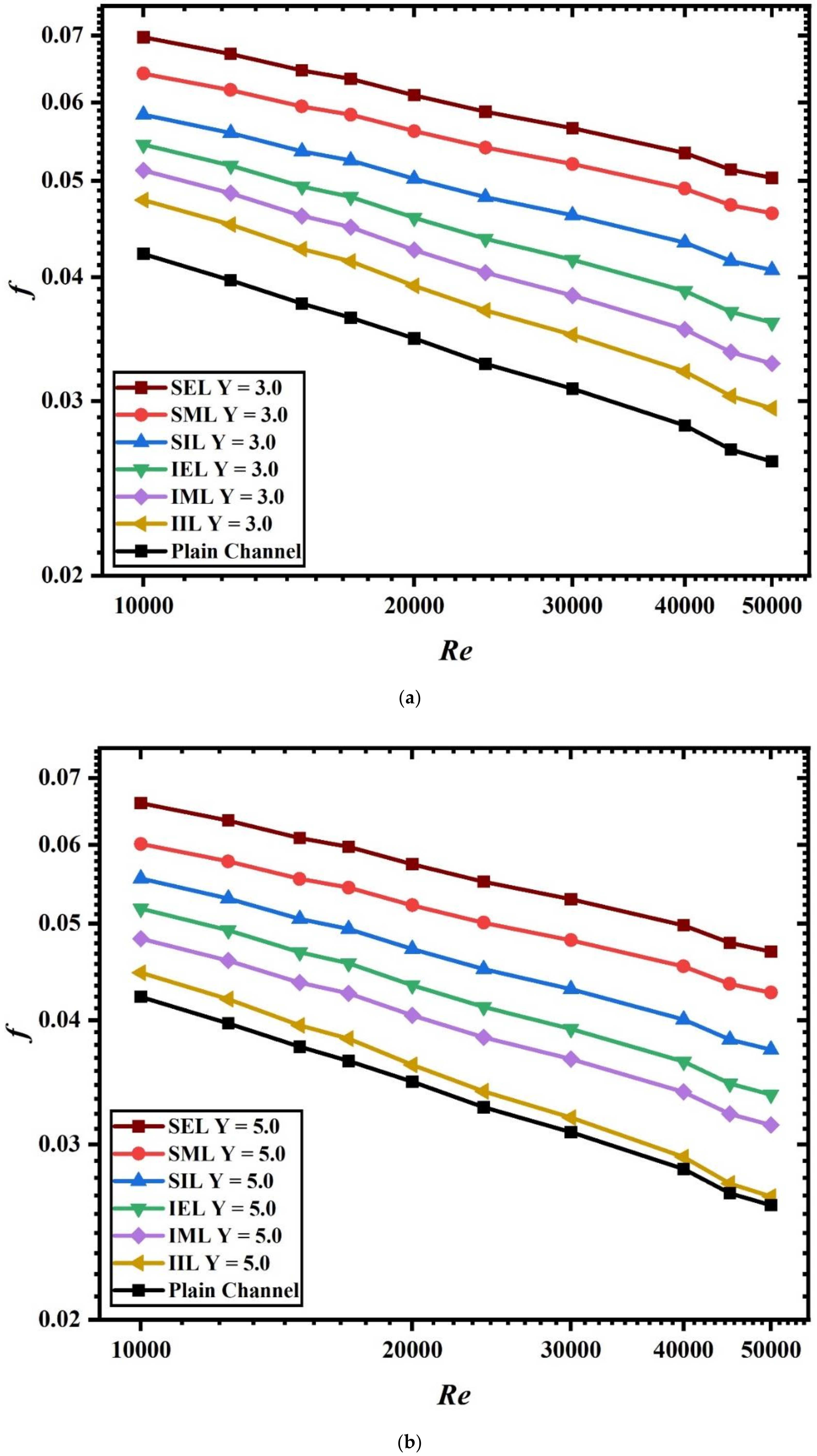
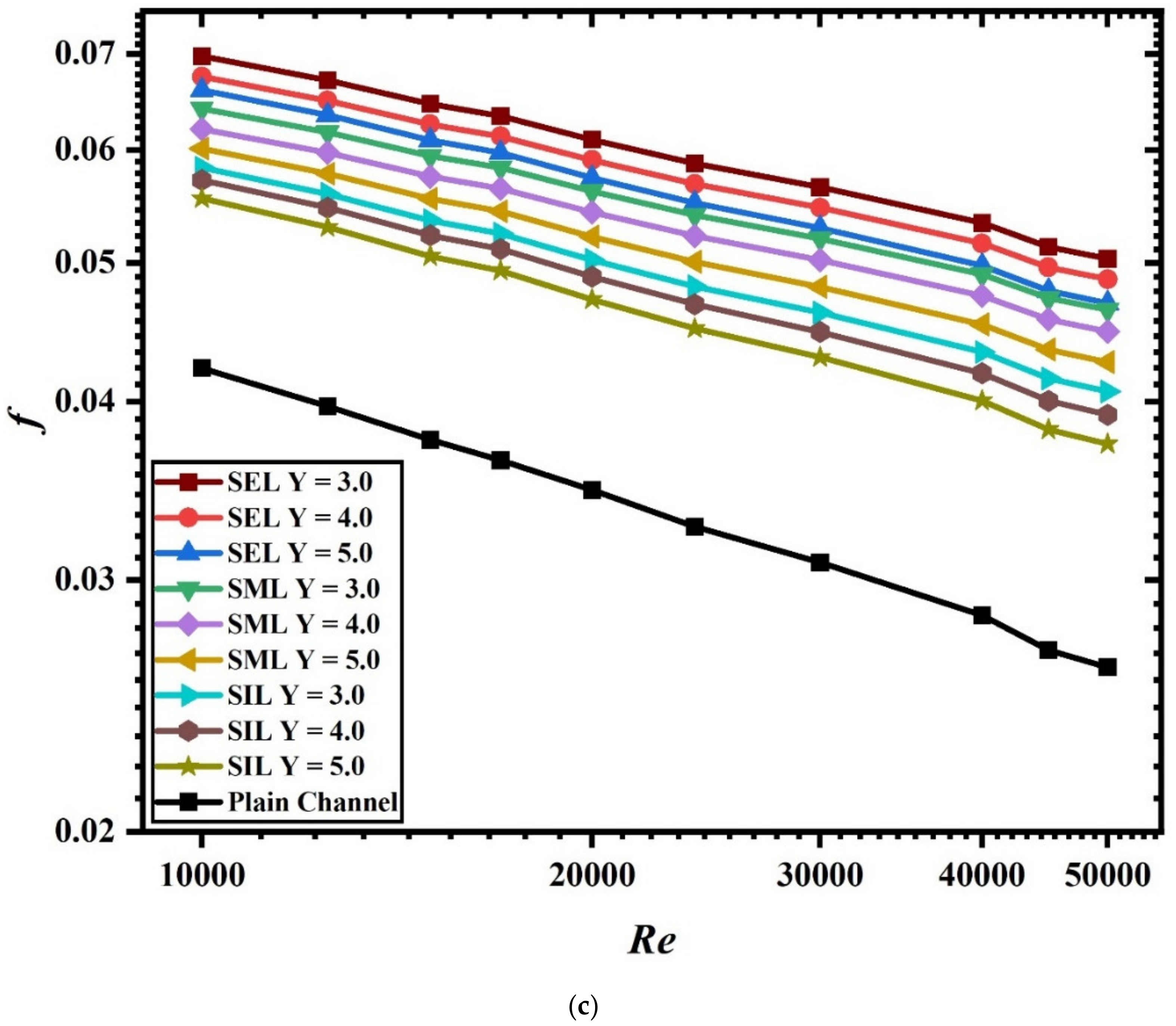
5.3. Friction Factor

Figure 5a–c shows the variation of f with Re for pitch ratios of Y = 3.0 and Y = 5.0 and staggered baffles, respectively. The figures clearly show a decrease of the friction factor with Reynolds number. The maximum f was obtained for SEL baffles having Y = 3.0, followed by SML and SIL (refer Figure 5a). This is because the baffles and their position obstructed the fluid flow, resulting in a larger pressure drop and, consequently, a higher f. The same trend was observed the case of inline baffles. When comparing the results for different pitch ratios, the baffles having a lower value of pitch ratio were associated with a higher friction factor, while the baffles having a higher pitch ratio were associated with a lower friction factor (refer Figure 5c). This was due to the higher flow obstruction offered by the staggered baffles.

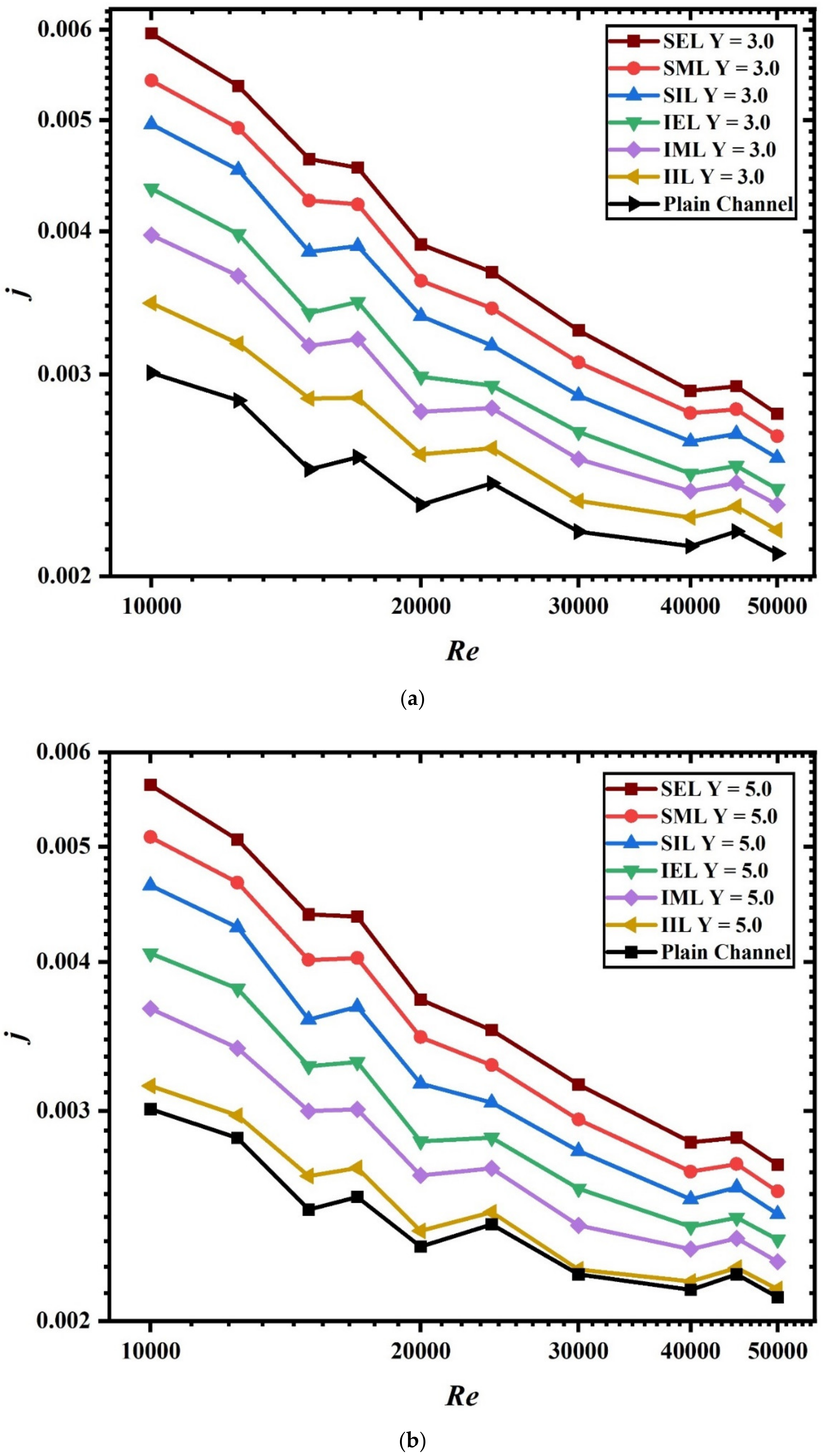
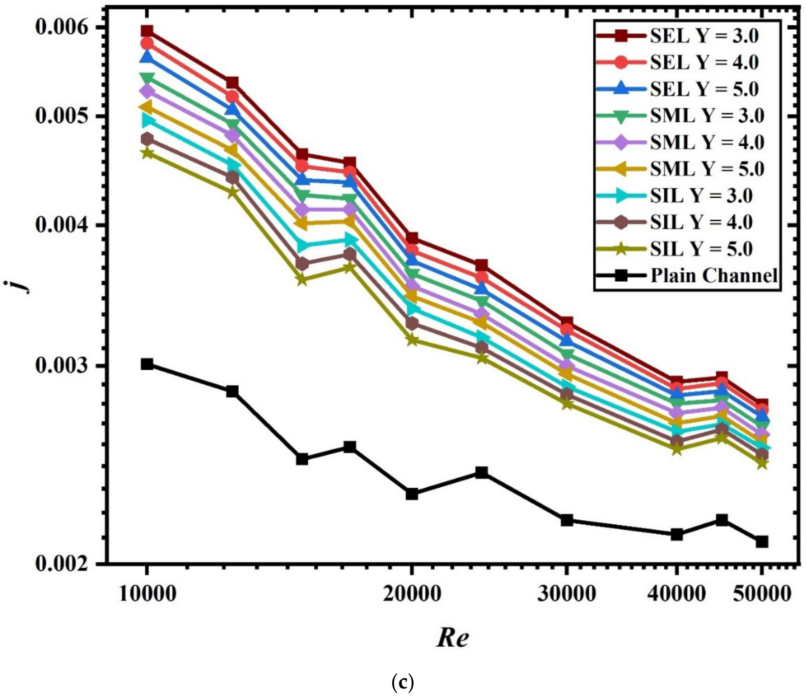
5.4. Colburn j-Factor
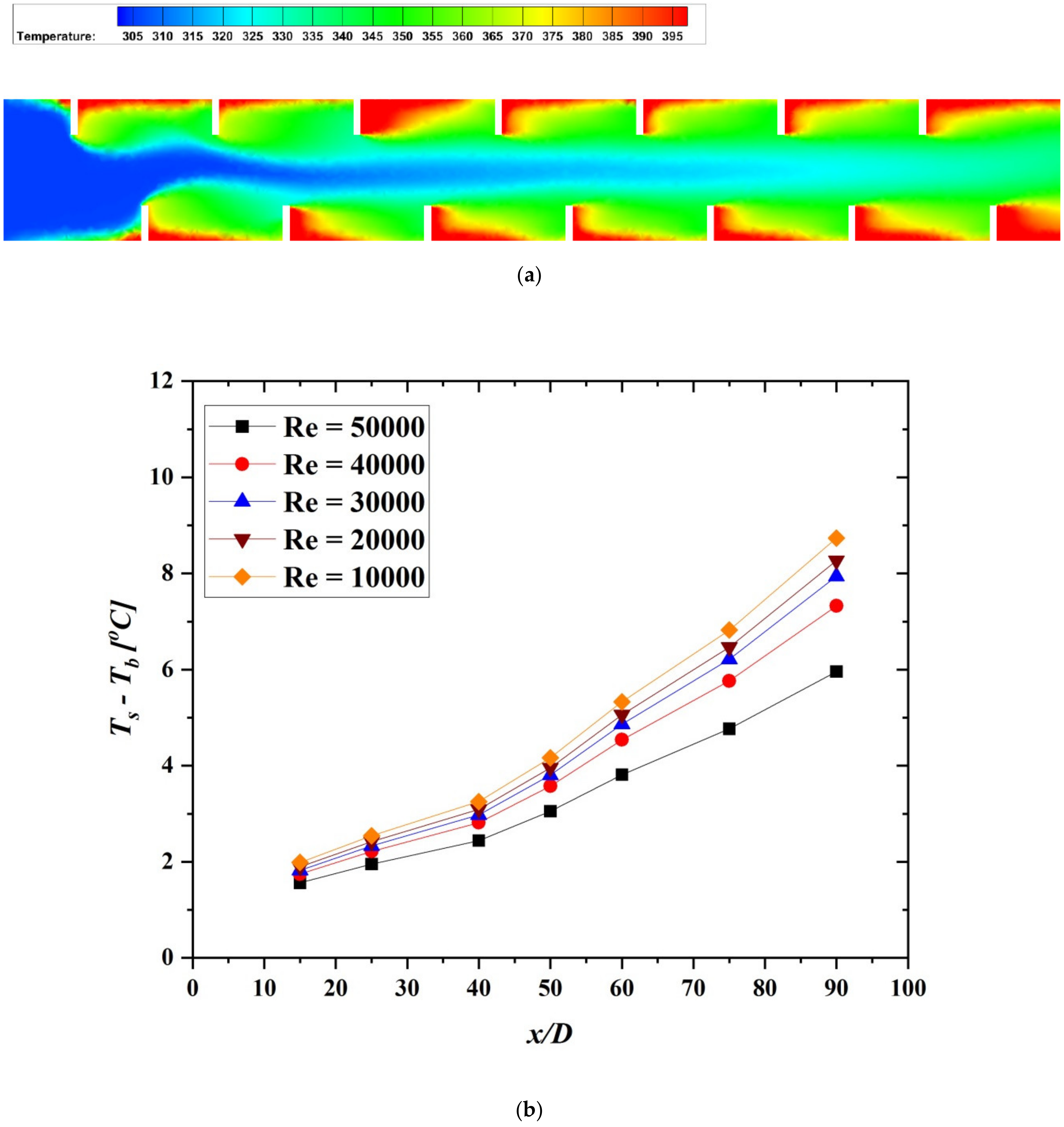
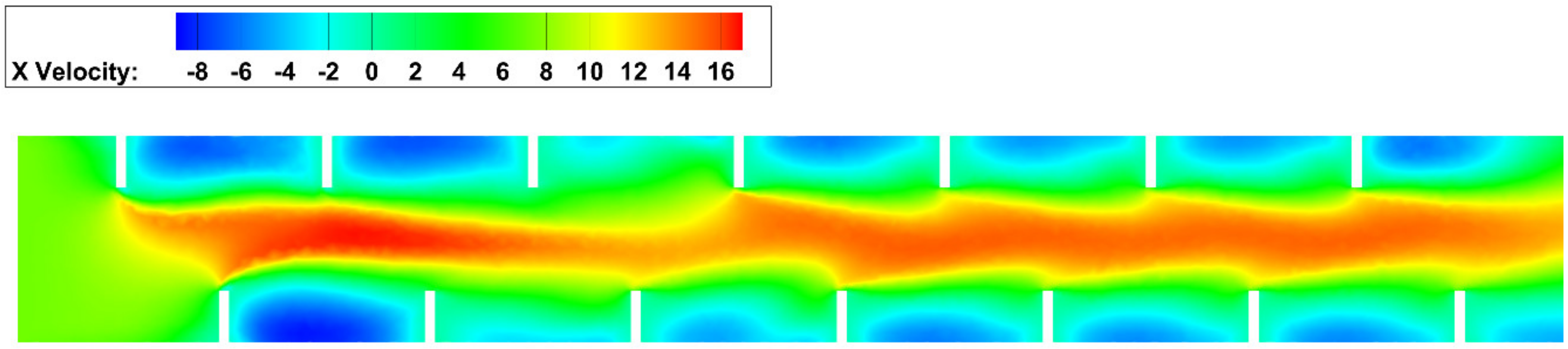
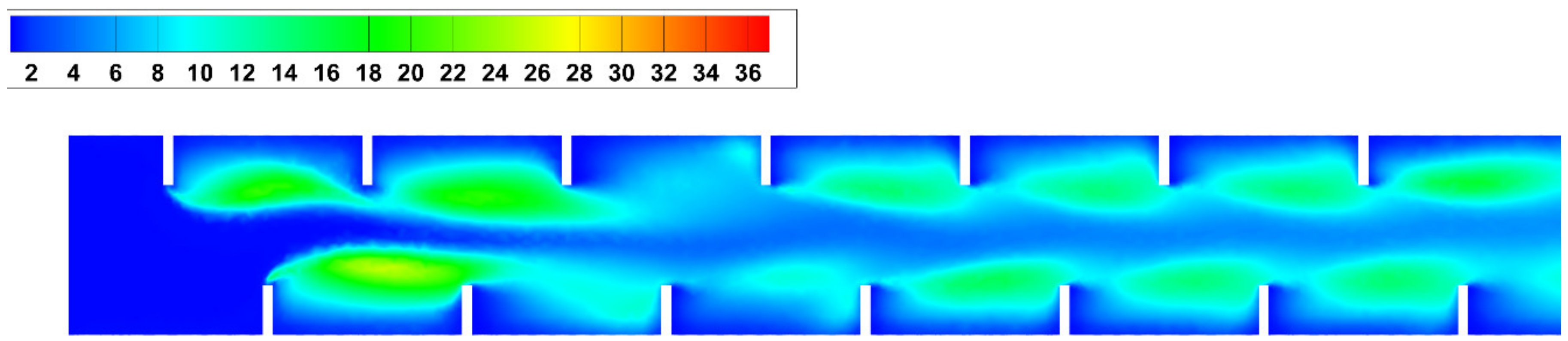
The Chilton–Colburn j-factor comparison is a popular and effective heat, momentum, and mass transfer analogy. Figure 6a–c shows the variation of j-factor with Reynolds number in the different cases under consideration. Figure 6a shows the result for Y = 3.0. It is clearly observed that the j-factor decreased with the increase of the Reynolds number. Secondly, the j-factor for SEL at Y = 3.0 was the highest. The disturbance in the channel generated by flow and heat transmission fully developed because the staggered baffles were positioned at the end of the channel. This led to an increase in heat transfer and j-factor. As compared to the plain channel, the j-factor value increased by 100% in the case of SEL at Y = 3.0. For constant Y = 5.0, as shown in Figure 6b, the trend was similar to that observed for Y = 3.0. The only difference was that the enhancement in all cases was lower than that observed for Y = 3.0. This was due to the distant placing of baffles consequent to the higher pitch. A larger gap between the baffles resulted in less swirling and mixing of the fluid. Due to this, the enhancement in the j-factor value was less. A comparison among various configurations of the staggered baffles is presented in Figure 6c. It can be clearly seen from the figure that SEL showed highest enhancement, followed by SML and SIL. In each case, the highest enhancement was noted for Y = 3.0, followed by Y = 4.0 and Y = 5.0.

5.5. Flow Field

Figure 7a shows the variation of the channel with SIL baffles. As clearly seen, the fluid at the core region was cooler than the fluid near the surface of the channel. The purpose of the baffles in the flow field is to intensify the mixing of the fluid. When the baffles were positioned at the inlet, mixing took place but was not very intense, which resulted in a larger temperature gradient between surface and core fluid. In the case of SEL, there was sufficient time and space for interaction with the fluid. This resulted in a lower temperature gradient between core and surface fluid, and the heat transfer rate increased.
Figure 7b illustrates the average local temperature of the heated surface around the periphery at different axial positions and constant heat flux. TsTb as a function of dimensional axial distance x/D is presented in Figure 7b. It is clear from the figure that the temperature values in the entry of the test section were nearly the same and represented forced convection thermal conditions. Then, the temperature increased until it reached a maximum value of nearly x/D = 90; this confirmed that the temperature difference between the surface and the fluid temperatures along the tube length in the fully developed region was not constant due to a change in the fluid’s properties.
Figure 8 shows the distribution of velocity in the fluid domain. It is interesting to note the asymmetrical pressure distribution around the baffles. Figure 9 shows the distribution of turbulent kinetic energy for inlet staggered baffles. Turbulent kinetic energy represents the average kinetic energy per unit mass associated with a swirling motion in the turbulent flow regime. The higher the turbulent kinetic energy, the more will be the eddies in the flow regime.

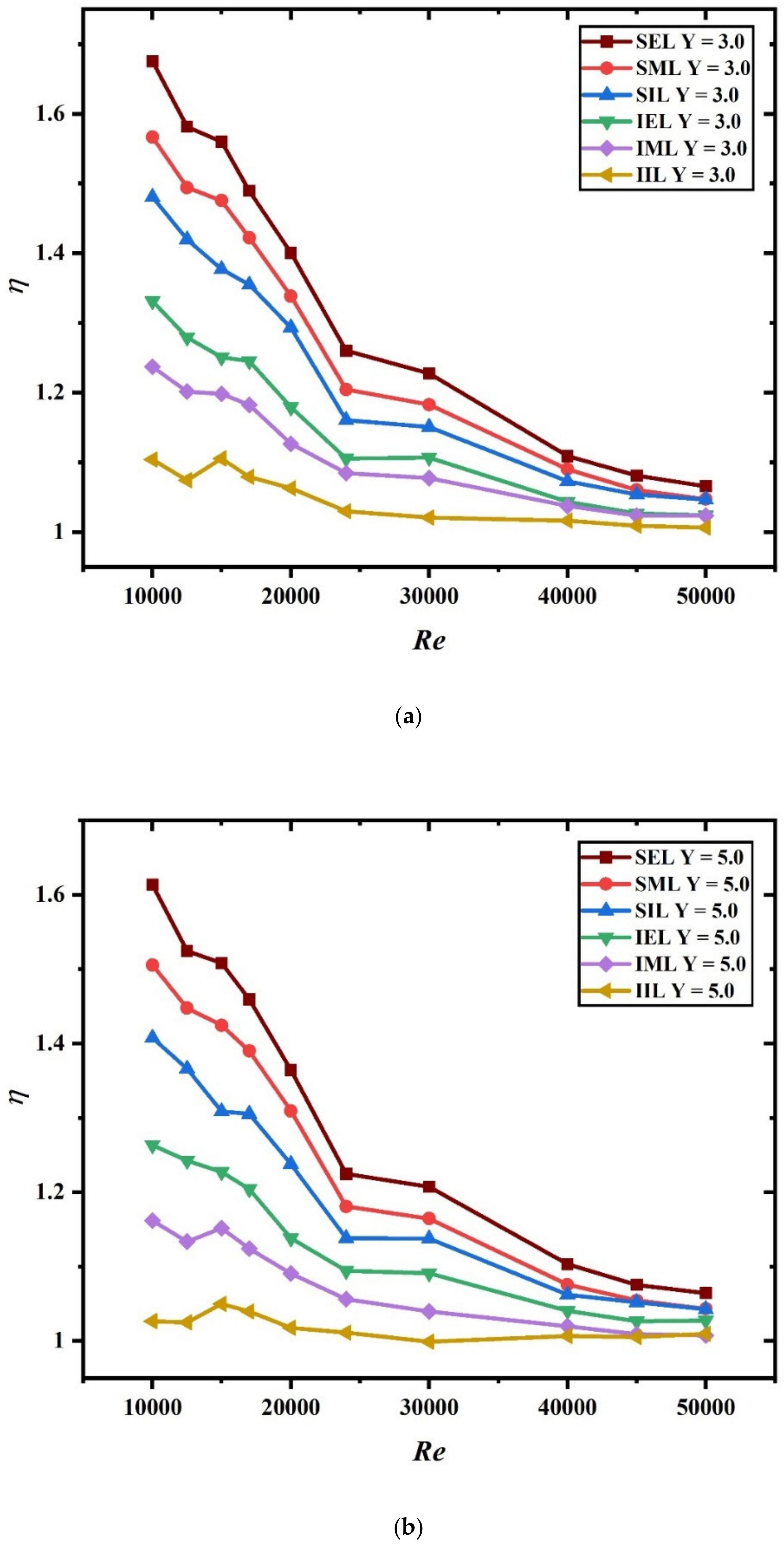
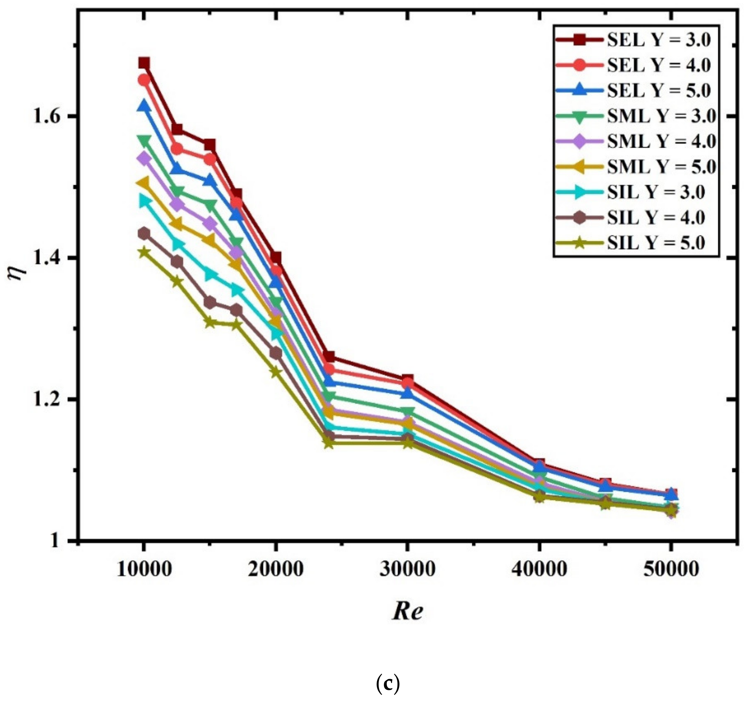
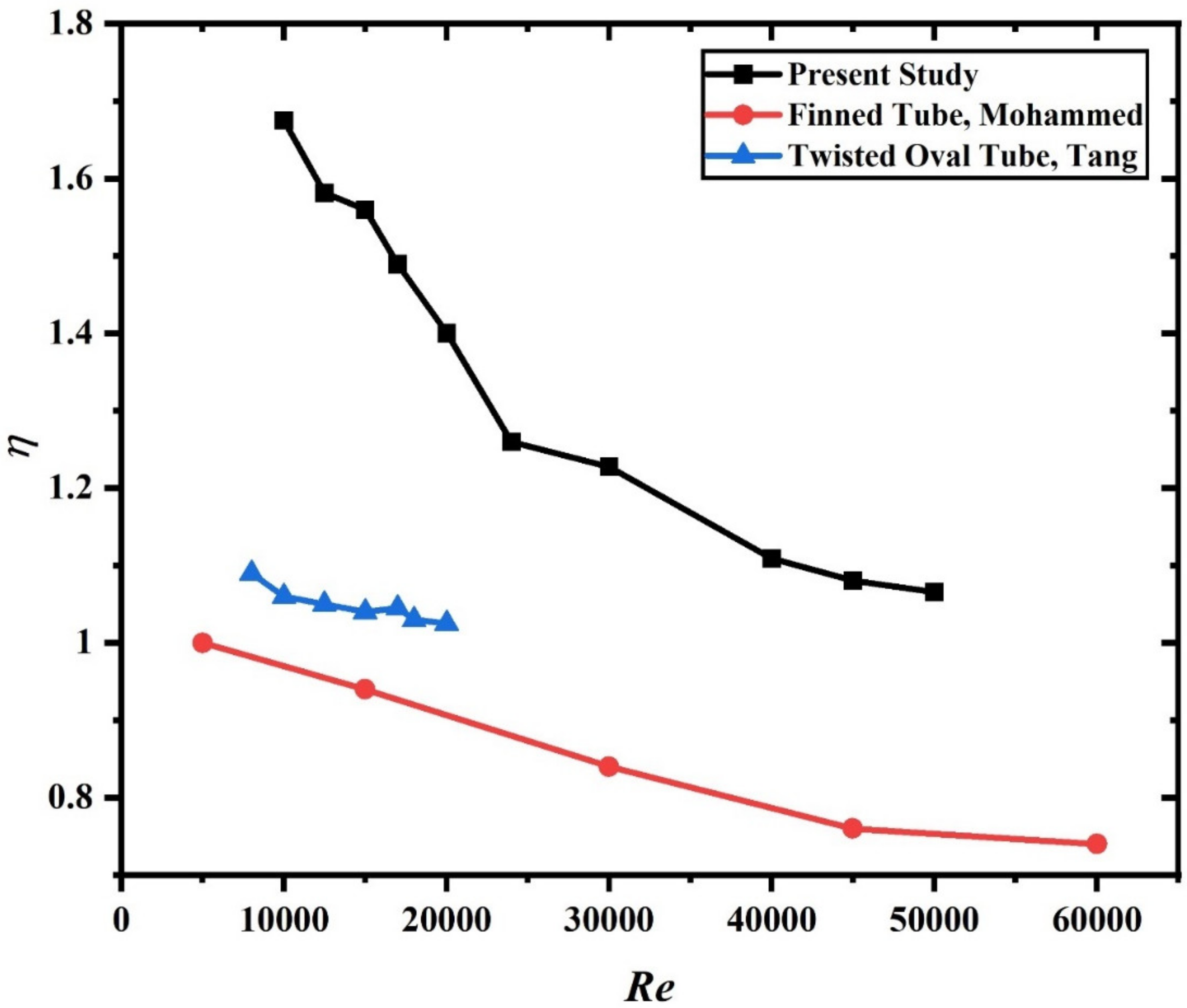
5.6. Thermal Performance Factor

The thermal performance factor, indicated by η, is the ratio of the enhancement in Nu to the f value at constant pumping power. This ratio provides an efficient way to evaluate the enhancement in thermal performance. Figure 10a–c shows the variation in the thermal performance factor as a function of Re for Y = 3.0, Y = 5.0, and staggered baffles, respectively. In all the studied cases, the value of thermal performance factor was higher than the unity. This indicates that the heat transfer enhancement was higher than f for a uniform pumping power. The highest enhancement in thermal performance was noted between Re 10,000 and 25,000. Beyond this point, the thermal performance started decreasing. As expected, the thermal performance remained the highest for the SEL baffles, followed by the SML and SIL baffles. A maximum 60% increase in the value of thermal performance for the SEL baffles was found.
Figure 11 shows the comparison of the present investigation with previous investigations using a Finned tube by Mohammad et al. and a twisted oval tube by Tang et al. In comparison to these earlier examined geometries, the current arrangement performed better.

6. Conclusions

The influence of a varied baffle positioning on Nu, f, Colburn j-factor, and thermal performance factor (η) was investigated. The goal of this research was to compare various baffle placements inside a heat exchanger tube. Three different configurations of baffles were compared with a plain channel. The major conclusions of the present numerical investigations are:
  • Staggered exit-length baffles showed the highest enhancement in Nusselt number, friction factor, j-factor, and thermal performance factor, while the least enhancement was reported for staggered inlet-length baffles.
  • For a pitch ratio of 3.0, the enhancement in all parameters was maximum, while at a pitch ratio of 5.0, the enhancement in all parameters was the least.
  • In all cases, the thermal performance factor value remained higher than the unity. Moreover, for SEL baffles at Y = 3.0, the enhancement was maximum at 1.6.
  • Staggered exit-length baffles appeared the best in terms of positioning as regards Nusselt number, j-factor, and thermal performance.

Author Contributions

Conceptualization, M.A.N. and B.S.; methodology, M.A.N. and B.S.; software, M.A.N. and B.S.; validation, M.A.N. and B.S.; formal analysis, M.A.N. and B.S.; investigation, M.A.N. and B.S.; resources, M.A.N. and B.S.; data curation, M.A.N. and B.S.; writing—original draft preparation, M.A.N. and B.S.; writing—review and editing, M.A.N. and B.S.; visualization, M.A.N. and B.S.; supervision, M.A.N. and B.S.; project administration, B.S.; funding acquisition, M.A.N.; All authors have read and agreed to the published version of the manuscript.

Funding

This work was supported by the Deanship of Scientific Research, King Faisal University, Saudi Arabia, Nasher track [grant number 206178].

Institutional Review Board Statement

Not applicable.

Informed Consent Statement

Not applicable.

Data Availability Statement

All data generated or analyzed during this study are included in this published article.

Acknowledgments

The authors acknowledge the Deanship of Scientific Research at King Faisal University for the financial support under Nasher track (Grant No. 206178).

Conflicts of Interest

The authors declare that there is no conflict of interest.

Nomenclature

ACross-section area
Dhydraulic diameter, m
ebaffle height, m
Fimodel blending functions
ffriction factor
hheat transfer coefficient, W m−2 K−1
HTheat transfer
jColburn j-factor
Ltube length, m
LWbaffle effective length, m
Mmodel constant
mmass flow rate of working fluid, kg/s
NuNusselt number
Ppitch
PDpressure drop
Pκturbulent kinetic energy production term
Prmolecular Prandtl number
Prturbturbulent Prandtl number
qheat flux, W m−2
ReReynolds number
Rwaverage thermal resistance of wall, ohm
RANSReynolds averaged numerical simulation
SSTshear stress transport
TTtwisted tape
Vbulk velocity, m s−1
Ypitch ratio
Greek Symbols
αmolecular thermal diffusivity, m2 sec−1
βimodel constant
σimodel constant
γintermittency
ΔPpressure drop, Pa
ηthermo-hydraulic performance factor
µmolecular dynamic viscosity, kg m−1 s−1
µturbturbulent dynamic viscosity, kg m−1 s−1
νmolecular kinematic viscosity, m2 s−1
νturbmolecular kinematic viscosity, m2 s−1
κ turbulence kinetic energy, m2 s−2
ω specific dissipation rate of κ , s−1

References

  1. Sahu, M.K.; Matheswaran, M.M.; Bishnoi, P. Experimental study of thermal performance and pressure drop on a solar air heater with different orientations of arc-shape rib roughness. J. Therm. Anal. Calorim. 2021, 144, 1417–1434. [Google Scholar] [CrossRef]
  2. Baig, W.; Ali, H.M. An experimental investigation of performance of a double pass solar air heater with foam aluminum thermal storage medium. Case Stud. Therm. Eng. 2019, 14, 100440. [Google Scholar] [CrossRef]
  3. Kumar, R.; Goel, V.; Kumar, M. Effect of providing gap in multiple-arc rib-roughened solar air heater—Part 1. J. Mech. Sci. Technol. 2020, 34, 2619–2625. [Google Scholar] [CrossRef]
  4. Thakur, D.S.; Khan, M.K.; Pathak, M. Solar air heater with hyperbolic ribs: 3D simulation with experimental validation. Renew. Energy 2017, 113, 357–368. [Google Scholar] [CrossRef]
  5. Bharadwaj, G.; Varun; Kumar, R.; Sharma, A. Heat transfer augmentation and flow characteristics in ribbed triangular duct solar air heater: An experimental analysis. Int. J. Green Energy 2017, 14, 587–598. [Google Scholar] [CrossRef]
  6. Jouybari, N.F.; Lundström, T.S. Performance improvement of a solar air heater by covering the absorber plate with a thin porous material. Energy 2020, 190, 116437. [Google Scholar] [CrossRef]
  7. Goel, V.; Kumar, R.; Bhattacharyya, S.; Tyagi, V.; Abusorrah, A.M. A comprehensive parametric investigation of hemispherical cavities on thermal performance and flow-dynamics in the triangular-duct solar-assisted air-heater. Renew. Energy 2021, 173, 896–912. [Google Scholar] [CrossRef]
  8. Bhattacharyya, S.; Benim, A.C.; Pathak, M.; Chamoli, S.; Gupta, A. Thermohydraulic characteristics of inline and staggered angular cut baffle inserts in the turbulent flow regime. J. Therm. Anal. Calorim. 2020, 140, 1519–1536. [Google Scholar] [CrossRef]
  9. Bhattacharyya, S.; Paul, A.R. The effect of circular hole spring tape on the turbulent heat transfer and entropy analysis in a heat exchanger tube: An experimental study. Exp. Heat Transf. 2020, 34, 1–20. [Google Scholar] [CrossRef]
  10. Bhattacharyya, S.; Benim, A.C.; Chattopadhyay, H.; Banerjee, A. Experimental investigation of heat transfer performance of corrugated tube with spring tape inserts. Exp. Heat Transf. 2018, 32, 411–425. [Google Scholar] [CrossRef]
  11. Bhattacharyya, S.; Chattopadhyay, H.; Benim, A.C. Heat Transfer Enhancement of Laminar Flow of Ethylene Glycol through a Square Channel Fitted with Angular Cut Wavy Strip. Procedia Eng. 2016, 157, 19–28. [Google Scholar] [CrossRef] [Green Version]
  12. Bhattacharyya, S.; Chattopadhyay, H.; Pal, T.K.; Roy, A. Numerical Investigation of Thermohydraulics Performance in Elliptical Twisted Duct Heat Exchanger. In CAD/CAM, Robotics and Factories of the Future; Lecture Notes in Mechanical Engineering; Springer: New Delhi, India, 2016; pp. 839–849. [Google Scholar] [CrossRef]
  13. Bhattacharyya, S.; Chattopadhyay, H.; Benim, A.C. Computational investigation of heat transfer enhancement by alternating inclined ribs in tubular heat exchanger. Prog. Comput. Fluid Dyn. Int. J. 2017, 17, 390. [Google Scholar] [CrossRef]
  14. Bhattacharyya, S.; Roy, A.; Chattopadhyay, H.; Rakshit, A. A Numerical Investigation Based on Heat Transfer and Fluid Flow Characteristics of Air in a Circular Tube Heat Exchanger with Inclined Ribs. Recent Adv. Chem. Eng. 2016, 11–20. [Google Scholar] [CrossRef]
  15. Bhattacharyya, D.K.; Vishwakarma, V.; Goel, S.; Chamoli, A.; Issakhov, J.P. Meyer, Thermodynamics and heat transfer study of a circular tube embedded with novel perforated angular-cut alternate segmental baffles. J. Therm. Anal. Calorim. 2021, 145, 1445–1465. [Google Scholar] [CrossRef]
  16. Sriromreun, P.; Thianpong, C.; Promvonge, P. Experimental and numerical study on heat transfer enhancement in a channel with Z-shaped baffles. Int. Commun. Heat Mass Transf. 2012, 39, 945–952. [Google Scholar] [CrossRef]
  17. Karwa, R.; Maheshwari, B.; Karwa, N. Experimental study of heat transfer enhancement in an asymmetrically heated rectangular duct with perforated baffles. Int. Commun. Heat Mass Transf. 2005, 32, 275–284. [Google Scholar] [CrossRef]
  18. Promvonge, P.; Kwankaomeng, S. Periodic laminar flow and heat transfer in a channel with 45° staggered V-baffles. Int. Commun. Heat Mass Transf. 2010, 37, 841–849. [Google Scholar] [CrossRef]
  19. Chamoli, S.; Thakur, N.S. Exergetic performance evaluation of solar air heater having V-down perforated baffles on the absorber plate. J. Therm. Anal. Calorim. 2014, 117, 909–923. [Google Scholar] [CrossRef]
  20. Rashidi, S.; Akbarzadeh, M.; Karimi, N.; Masoodi, R. Combined effects of nanofluid and transverse twisted-baffles on the flow structures, heat transfer and irreversibilities inside a square duct—A numerical study. Appl. Therm. Eng. 2018, 130, 135–148. [Google Scholar] [CrossRef] [Green Version]
  21. Menni, Y.; Ghazvini, M.; Ameur, H.; Ahmadi, M.H.; Sharifpur, M.; Sadeghzadeh, M. Numerical calculations of the thermal-aerodynamic characteristics in a solar duct with multiple V-baffles. Eng. Appl. Comput. Fluid Mech. 2020, 14, 1173–1197. [Google Scholar] [CrossRef]
  22. Samruaisin, P.; Kunnarak, K.; Chuwattanakul, V.; Eiamsa-Ard, S. Effect of sparsely placed twisted tapes installed with multiple-transverse twisted-baffles on heat transfer enhancement. J. Therm. Anal. Calorim. 2020, 140, 1159–1175. [Google Scholar] [CrossRef]
  23. Yu, J.-S.; Kim, J.-H.; Kim, J.-T. Effect of Triangular Baffle Arrangement on Heat Transfer Enhancement of Air-Type PVT Collector. Sustainability 2020, 12, 7469. [Google Scholar] [CrossRef]
  24. Bensaci, C.-E.; Moummi, A.; de la Flor, F.J.S.; Jara, E.A.R.; Rincon-Casado, A.; Ruiz-Pardo, Á. Numerical and experimental study of the heat transfer and hydraulic performance of solar air heaters with different baffle positions. Renew. Energy 2020, 155, 1231–1244. [Google Scholar] [CrossRef]
  25. Reddy, K.S.; Satyanarayana, G.V. Numerical Study of Porous Finned Receiver for Solar Parabolic Trough Concentrator. Eng. Appl. Comput. Fluid Mech. 2008, 2, 172–184. [Google Scholar] [CrossRef] [Green Version]
  26. Sari, A.; Sadi, M.; Sabet, G.S.; Mohammadiun, M.; Mohammadiun, H. Experimental analysis and exergetic assessment of the solar air collector with delta winglet vortex generators and baffles. J. Therm. Anal. Calorim. 2021, 145, 867–885. [Google Scholar] [CrossRef]
  27. Yaningsih, I.; Wijayanta, A.T.; Miyazaki, T.; Koyama, S. Thermal hydraulic characteristics of turbulent single-phase flow in an enhanced tube using louvered strip insert with various slant angles. Int. J. Therm. Sci. 2018, 134, 355–362. [Google Scholar] [CrossRef]
  28. Wijayanta, A.T.; Aziz, M.; Kariya, K.; Miyara, A. Numerical Study of Heat Transfer Enhancement of Internal Flow Using Double-Sided Delta-Winglet Tape Insert. Energies 2018, 11, 3170. [Google Scholar] [CrossRef] [Green Version]
  29. Wijayanta, A.T.; Aziz, M. Heat transfer augmentation of internal flow using twisted tape insert in turbulent flow. Heat Transf. Eng. 2020, 41, 1288–1300. [Google Scholar] [CrossRef]
  30. Menter, F.; Esch, T.; Kubacki, S. Transition modelling based on local variables. Eng. Turbul. Model. Exp. 2002, 5, 555–564. [Google Scholar] [CrossRef]
  31. Bhattacharyya, S.; Chattopadhyay, H.; Guin, A.; Benim, A.C. Investigation of Inclined Turbulators for Heat Transfer Enhancement in a Solar Air Heater. Heat Transf. Eng. 2018, 40, 1451–1460. [Google Scholar] [CrossRef]
  32. Bhattacharyya, S.; Chattopadhyay, H.; Biswas, R.; Ewim, D.R.E.; Huan, Z. Influence of Inlet Turbulence Intensity on Transport Phenomenon of Modified Diamond Cylinder: A Numerical Study. Arab. J. Sci. Eng. 2020, 45, 1051–1058. [Google Scholar] [CrossRef]
  33. Bhattacharyya, S.; Vishwakarma, D.; Chakraborty, S.; Roy, R.; Issakhov, A.; Sharifpur, M. Turbulent Flow Heat Transfer through a Circular Tube with Novel Hybrid Grooved Tape Inserts: Thermohydraulic Analysis and Prediction by Applying Machine Learning Model. Sustainability 2021, 13, 3068. [Google Scholar] [CrossRef]
  34. Kumar, A.; Dey, K.; Bhattacharyya, S.; Paul, A.R.; Benim, A.C.; Vishwakarma, D.K.; Huan, Z. Augmented thermal performance in a non-uniform heat flux circular tube with twisted tape insert using hybrid nanofluid. E3S Web Conf. 2021, 321, 04009. [Google Scholar] [CrossRef]
  35. Bhattacharyya, S.; Vishwakarma, D.K.; Soni, M.K. Heat Transfer and Pressure Drop in Transitional Flow: A Short Review. IOP Conf. Ser. Mater. Sci. Eng. 2021, 1080, 012050. [Google Scholar] [CrossRef]
  36. Bhattacharyya, S.; Chattopadhyay, H. Computational of studies of heat transfer enhancement in turbulent channel flow with twisted strip inserts. In Proceedings of the CHT-15, 6th International Symposium on Advances in Computational Heat Transfer, 25–29 May 2015; Rutgers University: New Brunswick, NJ, USA; Begellhouse: Danbury, CT, USA, 2015; p. 12. [Google Scholar]
  37. Olsen, L.; Bhattacharyya, S.; Cheng, L.; Minkowycz, W.; Abraham, J. Heat Transfer Enhancement for Internal Flows with a Centrally Located Circular Obstruction and the Impact of Buoyancy. Heat Transf. Eng. 2021, 1–24. [Google Scholar] [CrossRef]
  38. Bhattacharyya, S.H.; Chattopadhyay, S.K. Saha, Numerical Study on heat transfer enhancement of laminar flow through a circular tube with artificial rib roughness. J. Refrig. Air Cond. Heat. Vent. 2014, 3, 14–19. [Google Scholar]
  39. Bhattacharyya, S. The effects of short length and full length swirl generators on heat transfer and flow fields in a solar air heater tube. J. Therm. Anal. Calorim. 2019, 140, 1355–1369. [Google Scholar] [CrossRef]
  40. Bhattacharyya, S.; Benim, A.C.; Chattopadhyay, H.; Banerjee, A. Experimental and numerical analysis of forced convection in a twisted tube. Therm. Sci. 2019, 23, 1043–1052. [Google Scholar] [CrossRef] [Green Version]
  41. Bhattacharyya, S. Fluid Flow and Heat Transfer in a Heat Exchanger Channel with Short-Length Twisted Tape Turbulator Inserts. Iran. J. Sci. Technol. Trans. Mech. Eng. 2018, 44, 217–227. [Google Scholar] [CrossRef]
  42. Dittus, F.W.; Boelter, L.M.K. Heat transfer in automobile radiators of the tubular type. Int. Commun. Heat Mass Transf. 1985, 12, 3–22. [Google Scholar] [CrossRef]
  43. Blasius, H. Das Aehnlichkeitsgesetz bei Reibungsvorgängen in Flüssigkeiten. In Mitteilungen über Forschungsarbeiten auf dem Gebiete des Ingenieurwesens; Springer Science and Business Media LLC: Berlin/Heidelberg, Germany, 1913; pp. 1–41. [Google Scholar]
Figure 1. (a) Schematic of baffle, (b) schematic of channel with baffle, and (c) schematic of short length baffle.
Energies 14 08593 g001aEnergies 14 08593 g001b
Figure 2. Meshing of the Fluid Domain.
Energies 14 08593 g002
Figure 3. Validation with a plain channel: (a) Nusselt number and (b) friction factor.
Energies 14 08593 g003aEnergies 14 08593 g003b
Figure 4. Nusselt Number as a function of Reynolds number: (a) constant Y = 3.0 with different configurations, (b) constant Y = 5.0 with different configurations, and (c) staggered configuration with different pitch ratios.
Energies 14 08593 g004aEnergies 14 08593 g004b
Figure 5. Friction factor as a function of Reynolds number: (a) constant Y = 3.0 with different configurations, (b) constant Y = 5.0 with different configurations, and (c) staggered configuration with different pitch ratios.
Energies 14 08593 g005aEnergies 14 08593 g005b
Figure 6. Colburn j-factor as a function of Reynolds number: (a) constant Y = 3.0 with different configurations, (b) constant Y = 5.0 with different configurations, and (c) staggered configuration with different pitch ratios.
Energies 14 08593 g006aEnergies 14 08593 g006b
Figure 7. (a) Temperature distribution in the channel with staggered baffles at (SIL) Y = 3.0, Re = 20,000, (b) TsTb as a function of the dimensional axial distance x/D at different Re for SIL.
Energies 14 08593 g007
Figure 8. Velocity contour plot in the channel with staggered baffles at (SIL) Y = 3.0 at Re = 20,000.
Energies 14 08593 g008
Figure 9. Turbulent kinetic energy distribution in the channel with staggered baffles at (SIL) Y = 3.0, Re = 20,000.
Energies 14 08593 g009
Figure 10. Thermal performance factor as a function of Reynolds number: (a) constant Y = 3.0 with different configurations, (b) constant Y = 5.0 with different configurations, and (c) staggered configuration with different pitch ratios.
Energies 14 08593 g010aEnergies 14 08593 g010b
Figure 11. Comparison of the thermal performance factor with those of previous studies.
Energies 14 08593 g011
Table 1. Grid independence study.
Total Number of Grid NodesNuf
Re = 10,000, Plain Channel
Grid 11,195,75833.120.0411
Grid 21,374,38633.760.0422
Grid 31,589,36533.780.0422
Publisher’s Note: MDPI stays neutral with regard to jurisdictional claims in published maps and institutional affiliations.

