Article

Catalytic and Sulfur-Tolerant Performance of Bimetallic Ni–Ru Catalysts on HI Decomposition in the Sulfur-Iodine Cycle for Hydrogen Production

1
Zhejiang Institute of Metrology, Hangzhou 310018, China
2
State Grid Zhejiang Electric Power Research Institute, Hangzhou 310014, China
3
State Key Laboratory of Clean Energy Utilization, Zhejiang University, Hangzhou 310027, China
*
Author to whom correspondence should be addressed.
Energies 2021, 14(24), 8539; https://doi.org/10.3390/en14248539
Submission received: 15 October 2021 / Revised: 12 December 2021 / Accepted: 14 December 2021 / Published: 17 December 2021
(This article belongs to the Special Issue CO2 Reduction and H2 Promotion Techniques in Energies)

Abstract

:
The sulfur-iodine (SI) cycle holds great promise as an alternative large-scale process for converting water into hydrogen without CO2 emissions. A major issue regarding the long-term stability and activity of the catalysts is their poor sulfur deactivation resistance in the HI feeding process. In this work, the effect of Ru addition for enhancing the activity and sulfur resistance of SiO2-supported Ni catalysts in the HI decomposition reaction has been investigated. The presence of H2SO4 molecules in the HI results in severe sulfur deactivation of the Ru-free Ni/SiO2 catalysts by blocking the active sites. However, Ni–Ru/SiO2 catalysts show higher catalytic activity without sulfur-poisoning by 25% and exhibit more superior catalytic performance than the Ru-free catalyst. The addition of Ru to the Ni/SiO2 catalyst promotes the stability and activity of the catalysts. The experimental trends in activity and sulfur tolerance are consistent with the theoretical modeling, with the catalytic activities existing in the order Ni/SiO2 < Ni–Ru/SiO2. The effect of Ru on the improvement in sulfur resistance over Ni-based catalysts is attributed to electronic factors, as evidenced by theory modeling analysis and detailed characterizations.

1. Introduction

Hydrogen is considered as an environment-friendly fuel and sustainable energy vector. Due to its good thermal efficiency and operability, various important efforts have been made to promote hydrogen production via the thermochemical sulfur-iodine (SI) cycle [1,2,3,4,5,6,7,8,9]. The SI cycle consists of the following reactions [10]:
SO 2 ( g ) + I 2 ( s ) + 2 H 2 O ( l ) 293 - 393   K H 2 SO 4 ( aq ) + 2 HI ( aq )
2 HI ( g ) 573 - 773   K H 2 ( g ) + I 2 ( g )
H 2 SO 4 ( g ) 873 - 1173   K SO 2 ( g ) + H 2 O ( g ) + 1 / 2 O 2 ( g )
In Reaction (1) (Bunsen reaction), iodine from reaction (2) reacts with sulfur dioxide and water to generate sulfuric acid and hydrogen iodide. The products of Bunsen reaction are a mixture of H2SO4, hydrogen iodide (HI), and H2O. The mixture is required to be separated, thus processing the thermal decompositions of the two acids. Herein, two non-miscible acidic phases (sulfuric acid and the HIx phase) can be produced with an excess of iodine and water [11]. Accordingly, the two acidic phases are purified via a reverse Bunsen reaction at 423 K, and the purified HI is then catalytically dissociated into H2 and I2 at 573–773 K. The purified H2SO4 decomposes into O2, H2O, and SO2 at about 1073 K. The products from Reaction (2) and Reaction (3) can be entirely recycled in the SI cycle, except the H2 and O2.
Consequently, the net reaction of the SI cycle is complete water decomposition at relatively low temperatures. Reaction (2) is the key reaction, and it is hard to proceed without the help of a catalyst, even at 773 K, due to the relatively low homogeneous gas-phase conversion rate (only 2.2% at 773 K). Therefore, numerous HI decomposition catalysts have been studied to increase the conversion rate of HI decomposition.
Up to now, various catalysts have been assessed for use in the catalytic decomposition of HI, including noble metal elements (Pt, Au, Ru, Ag) [12,13], transition metals (Ni, Ce) [14,15,16], and activated carbon catalysts [17]. Among these, Pt, Ni, and Co loaded on CeO2 support have shown significant promise. The Pt/CeO2 has the best, and Co/CeO2 has the worst catalytic performance [18,19,20]. The effect of catalysts prepared by loading Ni onto different carbon materials has also been addressed, including Ni/MWCNT, Ni/CMS, Ni/AC, and Ni/GNP [21]. The activity performance and lifespan evaluation of Ni/γ-Al2O3 catalysts in HI decomposition have been determined at 773 K [22]. The catalytic kinetics of spheroidal activated carbon have also been studied, and the spherical activated carbon was stable at 140 h [23].
Much research on mechanism analyses has been conducted to develop a suitable and inexpensive catalyst for HI decomposition [24,25,26]. Nevertheless, sulfur-containing compounds have been previously observed in the iodidric solution [7,9,27,28,29,30]. Sulfur poisoning is one of the most critical factors in catalytic deactivation [31,32]. To the best of our knowledge, no current studies are focusing on the improvement of sulfur tolerance for HI decomposition. Consequently, it is essential to evaluate the deactivation mechanism from sulfur poisoning and reduce the presence of sulfur species on the catalyst. Ru is an active noble catalytic component, and the combination of Ni and Ru has been observed to perform multiple roles [33]. As far as we know, Ni–Ru catalysts have not been reported for use in the SI cycle. Therefore, this study synthesized Ni–Ru bimetallic catalysts and examined the catalytic activity and sulfur tolerance performance of Ni and Ni–Ru catalysts supported on SiO2 in HI decomposition reactions.

2. Experimental Methodology

2.1. Catalyst Preparation

All the chemicals in this study were analytical-grade reagents. The silicon dioxide (Aladdin Reagent Co., Ltd., Shanghai, China) was dried at 393 K for 2 h and then calcined in air at 973 K for 5 h before use. The nickel nitrate hexahydrate (5.60 g), ruthenium nitrosyl nitrate (0.48 g), and polyethylene glycol (5.86 g, average molecular weight = 1000) were dissolved in the solution of solvent containing 300 mL of deionized water and 100 mL of butanol. The mixture was refluxed at 393 K in an oil bath under vigorous stirring for 2 h. Then, 10 g of SiO2 was introduced with continuous stirring. The formed suspensions were evaporated at 393 K, until the solvent was removed and a paste-like sample formed. The sample was dried in an oven at 393 K for 12 h and subsequently calcined in air at 673 K for 5 h to prepare the supported Ni–Ru/SiO2 metal oxides. The mass percentage of Ni in the Ni–Ru/SiO2 was 10 wt%. The samples were first reduced for 2 h in a hydrogen atmosphere at 873 K. Subsequently, the samples were passivated at room temperature in an atmosphere of 1% oxygen. The monometallic Ni/SiO2 catalyst (10 wt% Ni) was produced via the same preparation method without adding ruthenium nitrosyl nitrate. The Ni and Ni–Ru were supported on SiO2, and defined as Ni/SiO2 and Ni–Ru/SiO2. These catalysts were pressed, crushed, and then sieved into 60–80 mesh particles.

2.2. Characterization

The morphology and elemental compositions of the catalysts were characterized using a transmission electron microscope (TEM) equipped with energy-dispersive X-ray spectroscopy (EDX) on a JEM-2010-HR (JEOL Ltd., Tokyo, Japan). The catalyst powders were ground and then coated on the surface of copper grids with ethanol. The framework structure of the catalysts was assessed using the X-ray diffraction (XRD) technique with a Rigaku K/max2550/PC (Rigaku Corporation, Tokyo, Japan) diffractometer at 40 kV and 100 mA (step time of 0.02 s and step size of 0.02°). X-ray photoelectron spectroscopy (XPS) analyses were performed on an Escalab 250Xi system (Thermo Scientific Ltd., Bedford, MA, USA) with MgK α radiation under ultra-high vacuum conditions (5 × 10⁻⁸ Pa). Temperature programmed reduction (TPR) was carried out with an AutoChem II 2920 automated catalyst characterization system (Micromeritics Instrument Corporation, Norcross, GA, USA). At the end of HI decomposition tests, the catalysts Ni/SiO2 and Ni–Ru/SiO2 were cooled to room temperature, discharged from the fixed-bed reactor, and then transferred to XRD and XPS studies. In this case no precautions were taken to prevent exposure of the catalysts to air prior to the XRD and XPS analysis.

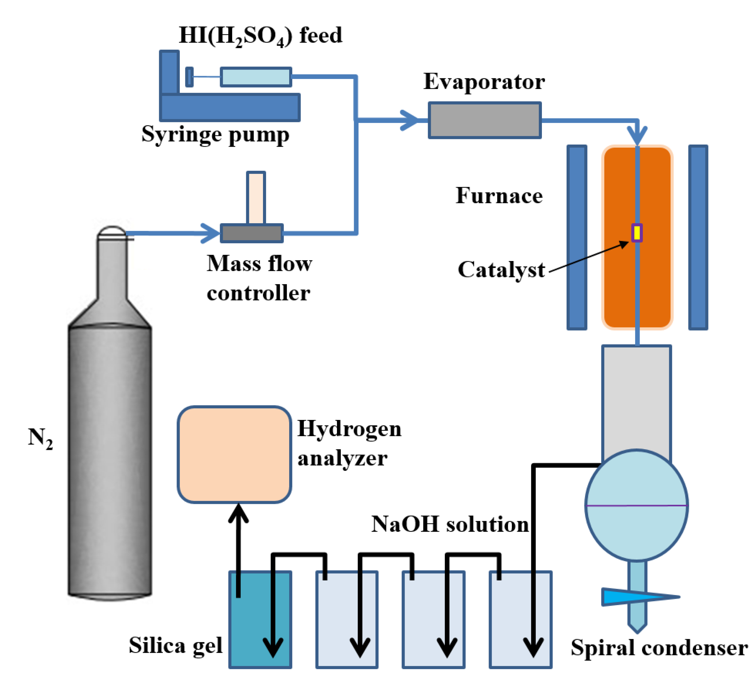
2.3. Catalyst Activity and Stability Test

The catalytic activity and sulfuric acid poisoning process were conducted in a flow fixed-bed reactor, as described in Figure 1. An automated system was installed to produce H2 from an HI decomposition reaction. A mass-flow controller and syringe pump were used to control the flow of the carrier gases. The fixed-bed reactor consists of an electric heater and a silica tube (18 mm in inner diameter × 458 mm in length). A type K thermocouple was equipped to monitor the reaction temperature in the middle of the catalysts bed. 0.5 g of catalyst, mixed uniformly with coarse quartz particles, was fed into the fixed-bed reactor. The feeding rate of hydroiodic acid (55 wt% at different concentrations of sulfuric acid) into the evaporator (433 K) was 0.5 mL/min and controlled via a syringe pump. 60 mL/min N2 was used to drive the vaporized HI. A stream of gaseous mixture subsequently entered the fixed-bed reactor. After the HI decomposition reaction, the mixed gases passed through a gyroidal water condenser, several NaOH solution absorbers, and silica gels, accomplishing the purification of residual H2 and N2. The outlet gases were collected and analyzed using a hydrogen analyzer.
The HI conversion can be expressed by the following equation:
α = 2 ND Rn 1 D
where α is the value of HI conversion. D denotes hydrogen concentration. R is the molar volume constant of gas. N is the volume flow rate of driving gas (N2), and n is the molar flow rate of HI solution.
The deactivation ratio can be expressed by following equation:
β = 1 α i α 0 × 100 %
where β is the value of deactivation ratio. α 0 denotes HI conversion in a standard HI decomposition step with an HI solution (55 wt%) in the absence of H2SO4. α i is the HI conversion in poisoning step with a solution at different H2SO4 concentrations, and i denotes poisoning steps at different H2SO4 concentrations.

2.4. Theoretical Modeling

The different adsorption energies of HI and S on various Ni–Ru clusters were assessed by the Vienna Ab-initio Simulation Package (VASP) [34,35], using the density functional theory (DFT) and the Projected Augmented Wave (PAW) methods [36]. The Perdew-Burke-Ernzerhof (PBE) function was used to express the exchange and correlation effect [37]. For all geometry optimizations, the cutoff energy was set to be 450 eV. Spin-polarization was included in the calculations of Ni-containing groups. The simulation models were constructed in a 19 Å × 19 Å × 19 Å box, which is sufficient to eliminate the influence of neighboring clusters. The Monkhorst-Pack grids were set to be 1 × 1 × 1 for all calculations [38].
The adsorption energy of HI and S on the Ni–Ru clusters was defined as:
E a d s = E a d s E s l a b E H I S
where Eads is the electronic energy of the cluster with an adsorbed HI or S, Eslab is the electronic energy of the clean cluster, and EHI(S) is the electronic energy of one HI or S. The electronic energy of one S atom was referenced as the energy of one S8 cluster. Under this definition, a more negative value indicated a stronger binding.

3. Results and Discussion

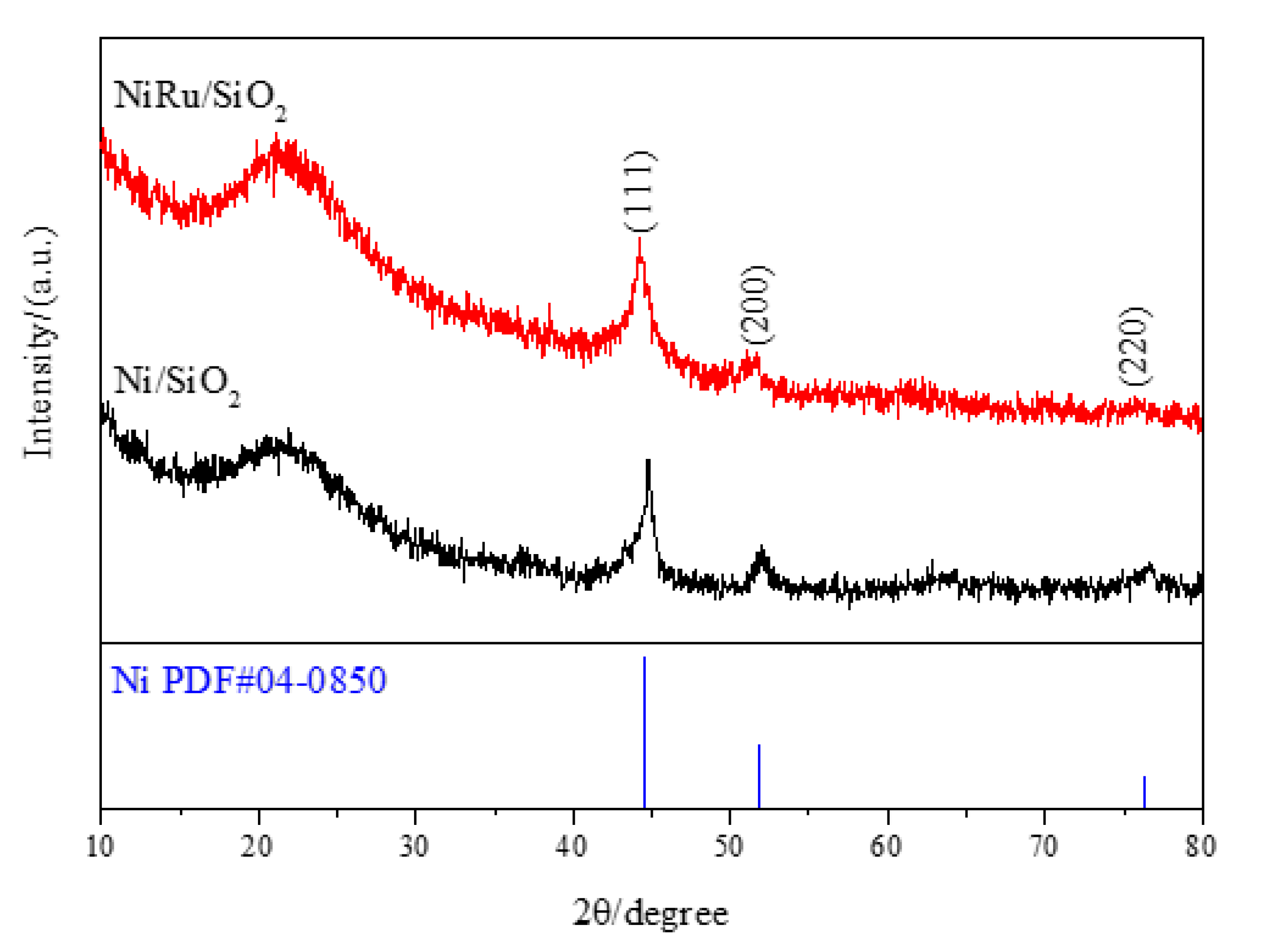
3.1. Properties of the Catalysts

As shown in Figure 2, the diffraction patterns of fresh Ni/SiO2 and Ni–Ru/SiO2 catalysts exhibit similar typical peaks. The pattern for the supports is that of crystallized materials with wide diffraction peaks in the 2θ range between 15 and 30, which are features of amorphous silica. Additionally, three diffraction peaks around 44.5, 51.85 and 76.37 are ascribed to the (111), (200) and (220) planes of the cubic structure of Ni [JCPDS No. 04-0850]. The presence of only metallic nickel in the XRD analyses indicates that most NiO phases are reduced to form metallic Ni during the pre-reduction of the catalyst, which may have been active for HI decomposition. No significant diffraction peak of Ru is detected in the Ni–Ru/SiO2 catalysts. These results suggest that the Ru is well dispersed on the SiO2. The particle size of Ru is very small, and the dispersion of the granules is homogeneous.
The TEM micrographs are used to observe the sizes and morphologies of the species on the catalysts. As shown in Figure 3, the fresh Ni–Ru/SiO2 catalysts are investigated by TEM-EDX. It is noted that the nickel and ruthenium particles are small and homogeneously dispersed on the SiO2 surface. Further EDX analysis of the Ni–Ru/SiO2 catalysts are used to characterize the particles on the catalysts, as shown in Figure 3b. The Ni, Ru, O, and Si elements are clearly deposited. These observations suggested that the bimetallic Ni–Ru species are spread on the Ni–Ru/SiO2 catalysts.
The TPR profiles of the Ni/SiO2 and Ni–Ru/SiO2samples are shown in Figure 4. For the Ni/SiO2 catalyst, a large hydrogen-consuming peak at 562 K accompanied by an obvious shoulder between 650 and 850 K is observed. The former reduction peak can be ascribed to the reduction of NiO species contacting weakly with the SiO2 supports, and the high-temperature shoulder peak around 700 K indicates the formation of hard-reducible NiO species bearing a strong interaction with the SiO2 support [39]. The hydrogen consumption peak of the Ni–Ru/SiO2 sample around 453 K can be attributed to the reduction of RuO2 (RuO2 + H2 → Ru + H2O), which can be easily reduced at a comparatively low temperature. Additionally, this peak markedly overlaps with the subsequently large H2 consuming peaks, and the NiO reduction temperature obviously changes from 562 K to 549 K, implying that active hydrogen species produced at the pre-generated Ru0 particles could easily spill into adjacent NiO sites to promote their reduction [33]. Therefore, the reducibility of the Ni–Ru/SiO2 catalysts is significantly increased, in contrast to the Ru-free Ni/SiO2 samples. In accordance with the literature [40], the appearance of the overlapping hydrogen-consuming peaks indicates that the RuO2 species can closely interact with the NiO species, resulting in their high dispersion on the Ni–Ru/SiO2 sample. This effect may accelerate the reduction of NiO with a lower interaction. Moreover, it can be conjectured that the presence of Ru on the catalyst decreases the interactions between the small NiO particles and the supports; hence, improving the reducibility and facilitating the formation of bimetallic Ni–Ru species.

3.2. Catalytic Activity and Sulfur-Tolerant Performance

The experimental data of the measured HI conversion rate versus the reaction time over the Ni/SiO2 and Ni–Ru/SiO2 catalyst with different H2SO4 concentrations is presented in Figure 5a. The activity and poisoning experiments were investigated via a series of different conduct steps. Initially, a standard HI decomposition step with an HI solution (55 wt%) is used in the absence of H2SO4 at 773 K. Subsequently, various poisoning steps were executed, in which a solution at different H2SO4 concentrations (500, 1000, 2000, and 3000 ppm), HI (55 wt%), and H2O were pumped in the test facility. Finally, at the end of the 800-min experiment, the standard HI decomposition step was repeated, closely following the poisoning steps, without changing the catalysts. These steps were continuously processed and monitored. Under the same experimental conditions of the standard HI decomposition, the HI conversion over Ni–Ru/SiO2 is strongly promoted from 16% to 20% compared to Ni/SiO2. As is evident, the addition of Ru to the Ni catalysts significantly promotes the HI decomposition reaction. However, as can be seen in Figure 5a, significant changes in the HI conversion rate are observed over both catalysts in the poisoning steps, even at 500 ppm. It is to be noted that the activity of the Ni/SiO2 is obviously weakened in the poisoning step (3000 ppm H2SO4), which was about a quarter of the activity prior to H2SO4 poisoning. Importantly, the deactivation effect was markedly reversible, indicating that the regeneration of some sulfur-poisoned sites may be achieved. In the repeated standard HI decomposition step without H2SO4 contamination, the activity of the Ni/SiO2 becomes partly irreversible. Moreover, upon removal of H2SO4, the activity of the Ni–Ru/SiO2 catalysts returns to nearly the same level as prior to the H2SO4 exposure. The reversible deactivation is primarily based on competitive adsorption due to the sulfur species deposition on the catalyst surface [32]. It is concluded that Ni–Ru/SiO2 exhibits better activity in all the above steps.
Figure 5b shows the deactivation ratios at the different H2SO4 concentrations. Notably, the deactivation rates are gradually varied, and this can be due to the H2SO4 concentration gradients and the possible loss of the catalyst activities. Meanwhile, Ni/SiO2 has more severe deactivation compared to Ni–Ru/SiO2. This indicates that Ni–Ru/SiO2 could resist the sulfur poisoning. These results show that the addition of Ru to the Ni/SiO2 catalyst promotes the stability and activity of the catalysts.

3.3. Characterization of the Deactivated Catalysts

The crystal structures of the deactivated catalysts after exposure to the H2SO4-containing HI solution are observed by XRD, and the results are presented in Figure 6. Different from the Ni/SiO2, the Ni–Ru/SiO2 catalyst has a small peak around 28.09, 35.11 and 54.38°, which is the diffraction peak of RuO2 [JCPDS No. 70-2662]. It also has an NiO crystal peak around 39.26, 43.29 and 62.89° [JCPDS No. 89-5881], and exhibits the characteristic diffraction peak of Ni2O3 (2θ ≈ 39.13 and 51.59°) [JCPDS No. 14-0481]. It is possible to conclude that the appearance of the small amounts of RuO2 and nickel oxide reflections in XRD patterns can be explained by contact of discharged samples with air, since such oxides could not be stable in the presence of hydrogen in the HI decomposition tests. In addition, the peak of the Ni2SiO4 phase is observed for the Ni/SiO2 catalyst [JCPDS No. 74-0563], which shows that some nickel silicate has formed on the Ni/SiO2 sample. This indicates that the Ni species strongly interacts with the SiO2 supports, as the silica and nickel oxide gradually transform to nickel silicate during the H2SO4 poisoning process.
On the other hand, after long reaction times, the reflections of cristobalite [JCPDS No. 75-0923] appear in diffraction patterns of the poisoned Ni/SiO2 and Ni–Ru/SiO2 catalysts while being absent in the patterns of fresh initial samples. This indicates that the presence of sulfuric acid along with steam in reaction conditions facilitates silica crystallization. Such crystallization weakens the interaction of support with Ni and Ru, resulting in the aggregation of catalysts. The calculated crystal diameters of the poisoned samples are larger than the fresh catalysts. These observations reveal that trace H2SO4 contamination in the HI contributed to the sintering of Ni0 particles and their aggregation, while no NiSx crystals appear on the catalysts.
XPS is used to detect the surface composition of the catalysts and provide further evidence of their electronic structures. Nevertheless, there is no S element existing based on the XPS analysis for each poisoned catalyst. Therefore, the oxidation state on the Ni surface is the only concern. At the Ni 2p3/2 level of the fresh Ni–Ru/SiO2 and Ni/SiO2 catalysts (as shown in Figure 7), the prominent asymmetric peaks of NiO species appear at 855 eV, accompanied by the obvious shoulder peaks. These results are consistent with the TPR results (Figure 2).
Additionally, the shoulder peak at 852 eV is attributed to the Ni0 species [41]. It is noted that the poisoned Ni/SiO2 and Ni–Ru/SiO2 catalysts consists of the nickel in higher oxidation states (e.g., Ni2+), possibly in oxidic or hydrated form, with small amounts of the Ni0. It confirms that nickel was relatively easy to be oxidized in the presence of oxygen if no precautions are taken to prevent exposure of the discharged catalysts to air.

3.4. Adsorption Modeling

Although the activity loss in the presence of H2SO4 for the HI decomposition reaction is primarily due to competitive sulfur species adsorption at the active sites, the mechanism of the reactions between the sulfur-containing contaminants remains unclear, and the bimetallic effect may be complex. It is desirable to gain a further mechanism understanding of the chemical composition and particle structure in regard to competitive sulfur species adsorption, as this may contribute to the further exploration and the development of highly sulfur-tolerant Ni-based catalysts. Accordingly, computational modeling is used to assess the adsorption energies of HI and S on the bimetallic and Ni-based surfaces. In particular, dissociative sulfur-species adsorption has been shown to constantly happen on the surfaces or clusters of transition metals [42]. Therefore, the various structures of tetrahedral clusters are focused on modeling the Ni and bimetallic surfaces. Furthermore, the adsorption of HI on the Ru, Ni–Ru, and Ni clusters are explored. Figure 8a illustrates that the adsorption of HI on the Ni clusters appears to be much less significant than that on the Ni–Ru and Ru clusters. The HI absorption in the presence of Ru is much stronger, and this may be the major reason that Ni–Ru/SiO2 demonstrates a better activity than that of Ni/SiO2.
Figure 8b presents the adsorption energies and the most stable geometries of S adsorption on the clusters. The differences in sulfur adsorption energies among the five kinds of clusters provides insights into the S resistance of the bimetallic catalysts. The adsorption energy of S on the pure Ni4 surface is much more significant than on the Ru-containing clusters, suggesting that S deposition is lower on Ru compared to the Ni catalysts. Such adsorption S coverage will block the active sites and accelerate catalyst sintering. The Ru4 clusters show the lowest adsorption energy, demonstrating that S adsorption is less competitive on the Ru clusters than on the Ni–Ru or Ni clusters. Compared with the pure Ni4 clusters, the higher sulfur tolerance of the Ni–Ru binary metal may be explained by the weaker S blocking. Thus, calculation results of the S adsorption are consistent with the above experimental investigations, as no NiSx crystals are observed experimentally on the Ni or Ni–Ru catalysts. The addition of Ru promotes activity and sulfur resistance of the catalyst for HI decomposition by reducing the S adsorption, as evidenced by the theoretical modeling analyses. Consequently, the Ni–Ru/SiO2 catalyst can maintain a more significant activity and demonstrate increased sulfur-tolerance for HI decomposition.
Based on the previous analysis, it can be found that the addition of Ru can form a specific interaction with NiO and promote the reduction of NiO particles. The specific catalytic mechanism is shown in Figure 9. During the formation process of the Ni–Ru/SiO2 catalyst, RuO2 is firstly reduced to Ru metal particles at a relatively low temperature, and gradually correlates with NiO particles to form a NiO-Ru bimetallic structure. In the meantime, Ru can also activate H2 and easily produces a hydrogen overflow phenomenon, which promotes the formation of a Ni–Ru bimetallic structure. Additionally, the active hydrogen species generated at Ru particles can easily spill into the adjacent NiO particles, thus promoting their reduction reaction. According to the theoretical simulation results, the presence of Ru can enhance the HI adsorption over Ni–Ru/SiO2 catalyst. This makes the catalytic activity of Ni–Ru/SiO2 catalyst better than that of Ni/SiO2 catalyst. The Ni/SiO2 catalyst does not show enhanced sulfur resistance since single metal Ni or NiO particles do not reduce the adsorption of sulfur while Ni–Ru/SiO2 catalyst offers good sulfur resistance.

4. Conclusions

The effects of Ru addition on HI conversion and sulfur adsorption of Ni and Ni–Ru catalysts supported on SiO2 have been investigated in this study. TPR, TEM-EDX, XRD, and XPS techniques were used to observe their physicochemical properties. The experimental trends in activity and sulfur tolerance are consistent with the theoretical modeling, with the catalytic activities existing in the order Ni/SiO2 < Ni–Ru/SiO2, as the addition of Ru to a Ni catalyst can promote HI adsorption. Modeling calculations were applied to identify bimetallic Ni–Ru surfaces with lower sulfur adsorption and to enhance HI adsorption energies. In the presence of trace S species, the specific S coverage on the catalysts blocked the active sites and enhanced sintering. The adsorption modeling results are consistent with the experiments for the supported bimetallic Ni–Ru catalysts, demonstrating that sulfur resistance for the HI decomposition reaction is promoted by the bimetallic Ni–Ru catalysts, which can reduce the competitive adsorption of sulfur and minimize the effect of sulfur poisoning. The activity and sulfur tolerance of the catalysts are highly dependent on HI and S adsorption. The presence of Ru can increase the HI–Ni0 interaction and reduce S adsorption. Thus, a remarkable improvement in catalytic activity and sulfur tolerance of bimetallic Ni–Ru in HI decomposition was obtained, providing new insights for maintaining more significant activity during HI decomposition in the presence of sulfur.

Author Contributions

L.W.: Investigation, Methodology, Formal analysis, Writing-original draft preparation, writing—review and editing. K.Z.: Software, Methodology, Visualization, Supervision. Y.Q.: Formal analysis, Investigation. H.C.: Investigation, project administration. J.W.: validation, Z.W.: Conceptualization, Data curation, Formal analysis, project administration. All authors have read and agreed to the published version of the manuscript.

Funding

This research was funded by the Program of the Innovative Research Groups of the National Natural Science Foundation of China (No. 51621005).

Institutional Review Board Statement

Not applicable.

Informed Consent Statement

Not applicable.

Data Availability Statement

The authors declare that the main data supporting the findings of this study are available within the article file. Extra data are available from the corresponding author upon request.

Acknowledgments

This work was supported by the Program of the Innovative Research Groups of the National Natural Science Foundation of China (51621005) and Introducing Talents of Discipline to Universities (B08026).

Conflicts of Interest

The authors declare no conflict of interest. The funders have no role in the design of the study; in the collection, analyses, or interpretation of data; in the writing of the manuscript, or in the decision to publish the results.

References

  1. Singhania, A.; Bhaskarwar, A.N. TiO2 as a catalyst for hydrogen production from hydrogen-iodide in thermo-chemical water-splitting sulfur-iodine cycle. Fuel 2018, 221, 393–398. [Google Scholar] [CrossRef]
  2. Ying, Z.; Zheng, X.; Cui, G. Detailed kinetic study of the electrochemical Bunsen reaction in the sulfur–iodine cycle for hydrogen production. Energy Convers. Manag. 2016, 115, 26–31. [Google Scholar] [CrossRef]
  3. Dincer, I.; Balta, M.T. Potential thermochemical and hybrid cycles for nuclear-based hydrogen production. Int. J. Energy Res. 2011, 35, 123–137. [Google Scholar] [CrossRef]
  4. Singhania, A.; Krishnan, V.V.; Bhaskarwar, A.N.; Bhargava, B.; Parvatalu, D. Hydrogen-iodide decomposition over PdCeO2 nanocatalyst for hydrogen production in sulfur-iodine thermochemical cycle. Int. J. Hydrogen Energy 2018, 43, 3886–3891. [Google Scholar] [CrossRef] [Green Version]
  5. Ying, Z.; Zheng, X.; Zhang, Y.; Cui, G. Kinetic analysis of Bunsen reaction with HI existence in the thermochemical sulfur–iodine cycle for hydrogen production. Appl. Therm. Eng. 2018, 129, 41–49. [Google Scholar] [CrossRef]
  6. Tyagi, D.; Varma, S.; Bharadwaj, S. Pt/graphite catalyst for hydrogen generation by HI decomposition reaction in S-I thermochemical cycle. Int. J. Energy Res. 2015, 39, 2008–2018. [Google Scholar] [CrossRef]
  7. Bai, S.; Wang, L.; Han, Q.; Zhang, P.; Chen, S.; Meng, X.; Xu, J. Experimental study on the purification of HIx phase in the iodine-sulfur thermochemical hydrogen production process. Int. J. Hydrogen Energy 2013, 38, 29–35. [Google Scholar] [CrossRef]
  8. Tyagi, D.; Varma, S.; Bharadwaj, S.R. Mesoporous Carbon Supported Platinum Nanocatalyst: Application for Hydrogen Production by HI Decomposition Reaction in S-I Cycle. J. Nanosci. Nanotechnol. 2017, 17, 2177–2184. [Google Scholar] [CrossRef]
  9. Wang, L.; Imai, Y.; Tanaka, N.; Kasahara, S.; Kubo, S.; Onuki, K. Thermodynamic considerations on the purification of H2SO4 and HIx phases in the iodine-sulfur hydrogen production process. Chem. Eng. Commun. 2012, 199, 165–177. [Google Scholar] [CrossRef]
  10. Dokiya, M.; Kameyama, T.; Fukuda, K.; Kotera, Y. The study of thermochemical hydrogen preparation. III. An oxygen-evolving step through the thermal splitting of sulfuric acid. Bull. Chem. Soc. Jpn. 1977, 50, 2657–2660. [Google Scholar] [CrossRef]
  11. Le Duigou, A.; Borgard, J.-M.; Larousse, B.; Doizi, D.; Allen, R.; Ewan, B.C.; Priestman, G.H.; Elder, R.; Devonshire, R.; Ramos, V. HYTHEC: An EC funded search for a long term massive hydrogen production route using solar and nuclear technologies. Int. J. Hydrogen Energy 2007, 32, 1516–1529. [Google Scholar] [CrossRef]
  12. Hinshelwood, C.N.; Prichard, C.R. CCVII—The relation of homogeneous to catalysed reactions. The catalytic decomposition of hydrogen iodide on the surface of gold. J. Chem. Soc. Trans. 1925, 127, 1552–1559. [Google Scholar] [CrossRef]
  13. Hinshelwood, C.N.; Burk, E.R. CCCCII—The relation of homogeneous to catalysed reactions. The catalytic decomposition of hydrogen iodide on the surface of platinum. J. Chem. Soc. Trans. 1925, 127, 2896–2900. [Google Scholar] [CrossRef]
  14. Zhang, Y.W.; Wang, Z.H.; Zhou, J.H.; Cen, K.F. Ceria as a catalyst for hydrogen iodide decomposition in sulfur-iodine cycle for hydrogen production. Int. J. Hydrogen Energy 2009, 34, 1688–1695. [Google Scholar] [CrossRef]
  15. Zhang, Y.; Wang, Z.; Zhou, J.; Liu, J.; Cen, K. Experimental study of Ni/CeO2 catalytic properties and performance for hydrogen production in sulfur-iodine cycle. Int. J. Hydrogen Energy 2009, 34, 5637–5644. [Google Scholar] [CrossRef]
  16. Fu, G.S.; He, Y.; Zhang, Y.W.; Zhu, Y.Q.; Wang, Z.H.; Cen, K.F. Catalytic performance and durability of Ni/AC for HI decomposition in sulfur–iodine thermochemical cycle for hydrogen production. Energ. Convers. Manag. 2016, 117, 520–527. [Google Scholar] [CrossRef]
  17. Fu, G.; Wang, Z.; Zhang, Y.; Huang, Z.; Liu, J.; Zhou, J.; Cen, K. Effect of raw material sources on activated carbon catalytic activity for HI decomposition in the sulfur-iodine thermochemical cycle for hydrogen production. Int. J. Hydrogen Energy 2016, 41, 7854–7860. [Google Scholar] [CrossRef]
  18. Zhang, Y.; Wang, Z.; Zhou, J.; Liu, J.; Cen, K. Effect of preparation method on platinum-ceria catalysts for hydrogen iodide decomposition in sulfur-iodine cycle. Int. J. Hydrogen Energy 2008, 33, 602–607. [Google Scholar] [CrossRef]
  19. Zhang, Y.; Wang, Z.; Zhou, J.; Liu, J.; Cen, K. Catalytic decomposition of hydrogen iodide over pre-treated Ni/CeO2 catalysts for hydrogen production in the sulfur-iodine cycle. Int. J. Hydrogen Energy 2009, 34, 8792–8798. [Google Scholar] [CrossRef]
  20. Zhang, Y.; Zhou, J.; Wang, Z.; Liu, J.; Cen, K. Influence of the oxidative/reductive treatments on Pt/CeO2 catalyst for hydrogen iodide decomposition in sulfur-iodine cycle. Int. J. Hydrogen Energy 2008, 33, 2211–2217. [Google Scholar] [CrossRef]
  21. Zhang, Y.; Fu, G.; Wang, Z.; Lin, X.; Wang, L.; Kuang, M.; Whiddon, R.; Cen, K. HI Decomposition over carbon-based and Ni-impregnated catalysts of the sulfur–iodine cycle for hydrogen production. Ind. Eng. Chem. Res. 2015, 54, 1498–1504. [Google Scholar] [CrossRef]
  22. Favuzza, P.; Felici, C.; Lanchi, M.; Liberatore, R.; Mazzocchia, C.; Spadoni, A.; Tarquini, P.; Tito, A. Decomposition of hydrogen iodide in the S-I thermochemical cycle over Ni catalyst systems. Int. J. Hydrogen Energy 2009, 34, 4049–4056. [Google Scholar] [CrossRef]
  23. Favuzza, P.; Felici, C.; Nardi, L.; Tarquini, P.; Tito, A. Kinetics of hydrogen iodide decomposition over activated carbon catalysts in pellets. Appl. Catal. B Environ. 2011, 105, 30–40. [Google Scholar] [CrossRef]
  24. Kasahara, S.; Iwatsuki, J.; Takegami, H.; Tanaka, N.; Noguchi, H.; Kamiji, Y.; Onuki, K.; Kubo, S. Current R&D status of thermochemical water splitting iodine-sulfur process in Japan Atomic Energy Agency. Int. J. Hydrogen Energy 2017, 42, 13477–13485. [Google Scholar] [CrossRef]
  25. Zhang, Y.; Lin, J.; Wang, Z.; Wang, R.; Cen, K. Study of the mechanism of the catalytic decomposition of hydrogen iodide (HI) over carbon materials for hydrogen production. Int. J. Hydrogen Energy 2017, 42, 4977–4986. [Google Scholar] [CrossRef]
  26. Singhania, A. Catalytic Decomposition of Hydrogen-Iodide Over Nanocrystalline Ceria Promoted by Transition Metal Oxides for Hydrogen Production in Sulfur-Iodine Thermo-Chemical Cycle. Catal. Lett. 2018, 148, 1416–1422. [Google Scholar] [CrossRef]
  27. Parisi, M.; Giaconia, A.; Sau, S.; Spadoni, A.; Caputo, G.; Tarquini, P. Bunsen reaction and hydriodic phase purification in the sulfur–iodine process: An experimental investigation. Int. J. Hydrogen Energy 2011, 36, 2007–2013. [Google Scholar] [CrossRef]
  28. Guo, H.; Zhang, P.; Bai, Y.; Wang, L.; Chen, S.; Xu, J. Continuous purification of H2 SO4 and HI phases by packed column in IS process. Int. J. Hydrogen Energy 2010, 35, 2836–2839. [Google Scholar] [CrossRef]
  29. Sakurai, M.; Nakajima, H.; Onuki, K.; Shimizu, S. Investigation of 2 liquid phase separation characteristics on the iodine-sulfur thermochemical hydrogen production process. Int. J. Hydrogen Energy 2000, 25, 605–611. [Google Scholar] [CrossRef]
  30. Ying, B.; Zhang, P.; Hanfei, G.; Songzhe, C.; Laijun, W.; Jingming, X. Purification of sulfuric and hydriodic acids phases in the iodine-sulfur process. Chin. J. Chem. Eng. 2009, 17, 160–166. [Google Scholar]
  31. Sheng, Z.; Yufeng, H.; Jianming, X.; Xiaoming, W.; Weiping, L. SO2 poisoning and regeneration of Mn-Ce/TiO2 catalyst for low temperature NOx reduction with NH3. J. Rare Earths 2012, 30, 676–682. [Google Scholar] [CrossRef]
  32. Wang, L.; Zhu, Y.; Fu, G.; He, Y.; Zhang, Y.; Wang, Z. H2SO4 poisoning of Ru-based and Ni-based catalysts for HI decomposition in SulfurIodine cycle for hydrogen production. Int. J. Hydrogen Energy 2019, 44, 9771–9778. [Google Scholar] [CrossRef]
  33. Yuan, C.; Nan, Y.; Wang, X.; Wang, J.; Lv, D.; Li, X. The SiO2 supported bimetallic Ni–Ru particles: A good sulfur-tolerant catalyst for methanation reaction. Chem. Eng. J. 2015, 260, 1–10. [Google Scholar] [CrossRef]
  34. Kresse, G.; Furthmüller, J. Efficient iterative schemes for ab initio total-energy calculations using a plane-wave basis set. Phys. Rev. B 1996, 54, 11169–11186. [Google Scholar] [CrossRef]
  35. Kresse, G.; Hafner, J. Ab initio. Phys. Rev. B 1994, 49, 14251–14269. [Google Scholar] [CrossRef]
  36. Blöchl, P.E. Projector augmented-wave method. Phys. Rev. B 1994, 50, 17953–17979. [Google Scholar] [CrossRef] [Green Version]
  37. Perdew, J.P.; Burke, K.; Ernzerhof, M. Generalized Gradient Approximation Made Simple. Phys. Rev. Lett. 1996, 77, 3865–3868. [Google Scholar] [CrossRef] [Green Version]
  38. Monkhorst, H.J.; Pack, J.D. Special points for Brillouin-zone integrations. Phys. Rev. B 1976, 13, 5188. [Google Scholar] [CrossRef]
  39. Burattin, P.; Che, M.; Louis, C. Characterization of the Ni(II) phase formed on silica upon deposition-precipitation. J. Phys. Chem. B 1997, 101, 7060–7074. [Google Scholar] [CrossRef]
  40. Yao, N.; Ma, H.; Shao, Y.; Yuan, C.; Lv, D.; Li, X. Effect of cation-oligomer interactions on the size and reducibility of NiO particles on NiRu/SiO2 catalysts. J. Mater. Chem. 2011, 21, 17403–17412. [Google Scholar] [CrossRef]
  41. Czekaj, I.; Loviat, F.; Raimondi, F.; Wambach, J.; Biollaz, S.; Wokaun, A. Characterization of surface processes at the Ni-based catalyst during the methanation of biomass-derived synthesis gas: X-ray photoelectron spectroscopy (XPS). Appl. Catal. A Gen. 2007, 329, 68–78. [Google Scholar] [CrossRef]
  42. Alfonso, D.R. First-principles studies of H2S adsorption and dissociation on metal surfaces. Surf. Sci. 2008, 602, 2758–2768. [Google Scholar] [CrossRef] [Green Version]
Figure 1. Schematic of the test facility for assessing catalytic activity and poisoning.
Energies 14 08539 g001
Figure 2. XRD patterns of the fresh Ni/SiO2 and Ni–Ru/SiO2 catalysts.
Energies 14 08539 g002
Figure 3. TEM–EDX analysis of the Ni–Ru/SiO2 catalysts: (a) TEM photo; (b) EDX signature.
Energies 14 08539 g003
Figure 4. H2-TPR profiles of the Ni/SiO2 and Ni–Ru/SiO2 samples.
Energies 14 08539 g004
Figure 5. (a) Experimental HI conversion rate over Ni/SiO2 and Ni–Ru/SiO2 measured in serial runs and (b) deactivation ratios at different H2SO4 concentrations.
Energies 14 08539 g005
Figure 6. XRD patterns of the poisoned Ni/SiO2 and Ni–Ru/SiO2 catalysts after exposure to 3000 ppm H2SO4.
Energies 14 08539 g006
Figure 7. XPS measurements for 3000 ppm H2SO4 poisoned and fresh Ni/SiO2 and Ni–Ru/SiO2 catalysts in the Ni 2p region.
Energies 14 08539 g007
Figure 8. The most probable adsorption model and energies of (a) HI adsorbed onRu4, Ni1Ru3, Ni2Ru2, Ni3Ru1, andNi4 clusters, and (b) S adsorbed on Ru4, Ni1Ru3, Ni2Ru2, Ni3Ru1, and Ni4 clusters.
Energies 14 08539 g008
Figure 9. Mechanism schematic of Ni–Ru/SiO2 catalyst.
Energies 14 08539 g009
Publisher’s Note: MDPI stays neutral with regard to jurisdictional claims in published maps and institutional affiliations.

