
Water-Cooled Thermoelectric Generators for Improved Net Output Power: A Review


Abstract
:1. Introduction
2. The Influence of Cooling on the TEG Performance
3. Existing Cooling Methods
3.1. Conventional Channel
3.1.1. Low Temperature Waste Heat Recovery
3.1.2. Combustion
3.2. Microchannel and Minichannel
3.3. Impingement
3.4. Inserts
4. Discussion
5. Conclusions
Author Contributions
Funding
Institutional Review Board Statement
Informed Consent Statement
Acknowledgments
Conflicts of Interest
Nomenclature
| A | area, m2 |
| D | hydraulic diameter, m |
| h | heat transfer coefficient, W∙m−2∙K−1 |
| I | electrical current, A |
| K | thermal conductance, W∙K−1 |
| l | length of TEG leg, m |
| Nu | Nusselt number |
| P | power, W |
| Δp | pressure difference, Pa |
| heat flow rate, W | |
| R | electrical resistance, Ω |
| r | ) |
| T | temperature, K |
| flow rate, m3∙s−1 | |
| Greek letters | |
| α | Seebeck coefficient, V∙K−1 |
| η | efficiency |
| λ | thermal conductivity, W∙ m−1 K−1 |
| σ | electrical conductivity, S∙m−1 |
| Subscripts | |
| 0 | electrical load |
| C | cold side |
| H | hot side |
| hyd | hydraulic |
| n | n-type |
| net | net |
| p | p-type |
| W | water |
| Abbreviations | |
| CFD | Computational Fluid Dynamics |
| CHP | Combined Heat and Power system |
| CPU | Central Processing Unit |
| ORC | Organic Rankine Cycle |
| TEC | Thermoelectric Cooler |
| TEG | Thermoelectric Generator |
| USB | Universal Serial Bus |
References
- Rowe, D.M. CRC Handbook of Thermoelectrics; CRC Press: Boca Raton, FL, USA, 1995; ISBN 978-0-8493-0146-9. [Google Scholar]
- He, W.; Zhang, G.; Zhang, X.; Ji, J.; Li, G.; Zhao, X. Recent Development and Application of Thermoelectric Generator and Cooler. Appl. Energy 2015, 143, 1–25. [Google Scholar] [CrossRef]
- Elghool, A.; Basrawi, F.; Ibrahim, T.K.; Habib, K.; Ibrahim, H.; Idris, D.M.N.D. A Review on Heat Sink for Thermo-Electric Power Generation: Classifications and Parameters Affecting Performance. Energy Convers. Manag. 2017, 134, 260–277. [Google Scholar] [CrossRef]
- Twaha, S.; Zhu, J.; Yan, Y.; Li, B. A Comprehensive Review of Thermoelectric Technology: Materials, Applications, Modelling and Performance Improvement. Renew. Sustain. Energy Rev. 2016, 65, 698–726. [Google Scholar] [CrossRef]
- Champier, D. Thermoelectric Generators: A Review of Applications. Energy Convers. Manag. 2017, 140, 167–181. [Google Scholar] [CrossRef]
- Deasy, M.J.; Baudin, N.; O’Shaughnessy, S.M.; Robinson, A.J. Simulation-Driven Design of a Passive Liquid Cooling System for a Thermoelectric Generator. Appl. Energy 2017, 205, 499–510. [Google Scholar] [CrossRef] [Green Version]
- Shi, Y.; Wang, Y.; Mei, D.; Chen, Z. Wearable Thermoelectric Generator with Copper Foam as the Heat Sink for Body Heat Harvesting. IEEE Access 2018, 6, 43602–43611. [Google Scholar] [CrossRef]
- El-Adl, A.S.; Mousa, M.G.; Hegazi, A.A. Performance Analysis of a Passively Cooled Thermoelectric Generator. Energy Convers. Manag. 2018, 173, 399–411. [Google Scholar] [CrossRef]
- Gu, J.; Han, D.; Liu, Y.; Li, Y.; Jin, C.; Yu, W. Performance Analysis of a Thermoelectric Generator with Closed and Flooded Passive Cooling in Small-Scale Space. Energy Sustain. Dev. 2019, 51, 21–31. [Google Scholar] [CrossRef]
- Boccardi, S.; Ciampa, F.; Meo, M. Design and Development of a Heatsink for Thermo-Electric Power Harvesting in Aerospace Applications. Smart Mater. Struct. 2019, 28, 105057. [Google Scholar] [CrossRef]
- Jalil, S.A.; ElKabbash, M.; Li, Z.; Zhang, J.; Singh, S.; Zhan, Z.; Guo, C. Multipronged Heat-Exchanger Based on Femtosecond Laser-Nano/Microstructured Aluminum for Thermoelectric Heat Scavengers. Nano Energy 2020, 75, 104987. [Google Scholar] [CrossRef]
- Alghoul, M.A.; Shahahmadi, S.A.; Yeganeh, B.; Asim, N.; Elbreki, A.M.; Sopian, K.; Tiong, S.K.; Amin, N. A Review of Thermoelectric Power Generation Systems: Roles of Existing Test Rigs/Prototypes and Their Associated Cooling Units on Output Performance. Energy Convers. Manag. 2018, 174, 138–156. [Google Scholar] [CrossRef]
- Kumar, P.M.; Jagadeesh Babu, V.; Subramanian, A.; Bandla, A.; Thakor, N.; Ramakrishna, S.; Wei, H. The Design of a Thermoelectric Generator and Its Medical Applications. Designs 2019, 3, 22. [Google Scholar] [CrossRef] [Green Version]
- Karthick, K.; Suresh, S.; Hussain, M.M.M.D.; Ali, H.M.; Kumar, C.S.S. Evaluation of Solar Thermal System Configurations for Thermoelectric Generator Applications: A Critical Review. Sol. Energy 2019, 188, 111–142. [Google Scholar] [CrossRef]
- Hashim, H.T.; Rashid, F.L.; Kadham, M.J. Concentration Solar Thermoelectric Generator (CSTEG): Review Paper. JMERD 2021, 44, 435–447. [Google Scholar]
- Ding, L.C.; Akbarzadeh, A.; Tan, L. A Review of Power Generation with Thermoelectric System and Its Alternative with Solar Ponds. Renew. Sustain. Energy Rev. 2018, 81, 799–812. [Google Scholar] [CrossRef]
- Saleh, U.A.; Johar, M.A.; Jumaat, S.A.B.; Rejab, M.N.; Wan Jamaludin, W.A. Evaluation of a PV-TEG Hybrid System Configuration for an Improved Energy Output: A Review. IJRED 2021, 10, 385–400. [Google Scholar] [CrossRef]
- Ma, T.; Qu, Z.; Yu, X.; Lu, X.; Wang, Q. A Review on Thermoelectric-Hydraulic Performance and Heat Transfer Enhancement Technologies of Thermoelectric Power Generator System. Therm. Sci. 2018, 22, 1885–1903. [Google Scholar] [CrossRef] [Green Version]
- Patil, D.S.; Arakerimath, R.R.; Walke, P.V. Thermoelectric Materials and Heat Exchangers for Power Generation—A Review. Renew. Sustain. Energy Rev. 2018, 95, 1–22. [Google Scholar] [CrossRef]
- Sajid, M.; Hassan, I.; Rahman, A. An Overview of Cooling of Thermoelectric Devices. Renew. Sustain. Energy Rev. 2017, 78, 15–22. [Google Scholar] [CrossRef]
- Angrist, S.W. Direct Energy Conversion. In Allyn and Bacon Series in Mechanical Engineering and Applied Mechanics, 3rd ed.; Allyn and Bacon: Boston, MA, USA, 1976; ISBN 978-0-205-05581-4. [Google Scholar]
- Favarel, C.; Bédécarrats, J.-P.; Kousksou, T.; Champier, D. Experimental Analysis with Numerical Comparison for Different Thermoelectric Generators Configurations. Energy Convers. Manag. 2016, 107, 114–122. [Google Scholar] [CrossRef]
- Lu, X.; Yu, X.; Qu, Z.; Wang, Q.; Ma, T. Experimental Investigation on Thermoelectric Generator with Non-Uniform Hot-Side Heat Exchanger for Waste Heat Recovery. Energy Convers. Manag. 2017, 150, 403–414. [Google Scholar] [CrossRef]
- Esarte, J.; Min, G.; Rowe, D.M. Modelling Heat Exchangers for Thermoelectric Generators. J. Power Sources 2001, 93, 72–76. [Google Scholar] [CrossRef]
- Lesage, F.J.; Pagé-Potvin, N. Experimental Analysis of Peak Power Output of a Thermoelectric Liquid-to-Liquid Generator under an Increasing Electrical Load Resistance. Energy Convers. Manag. 2013, 66, 98–105. [Google Scholar] [CrossRef]
- Gould, C.A.; Shammas, N.Y.A.; Grainger, S.; Taylor, I. Thermoelectric Cooling of Microelectronic Circuits and Waste Heat Electrical Power Generation in a Desktop Personal Computer. Mater. Sci. Eng. B 2011, 176, 316–325. [Google Scholar] [CrossRef]
- Li, Y.H.; Wu, Z.H.; Xie, H.Q.; Xing, J.J.; Mao, J.H.; Wang, Y.Y.; Li, Z. An Experimental Investigation of a Thermoelectric Power Generation System with Different Cold-Side Heat Dissipation. IOP Conf. Ser. Mater. Sci. Eng. 2018, 292, 012063. [Google Scholar] [CrossRef]
- Patil, D.S.; Arakerimath, R.R.; Walke, P.V. Experimental Investigation and Optimization of a Low-Temperature Thermoelectric Module with Different Operating Conditions. WJE 2019, 16, 368–376. [Google Scholar] [CrossRef]
- Kumar, R.; Sonthalia, A.; Goel, R. Experimental Study on Waste Heat Recovery from an IC Engine Using Thermoelectric Technology. Therm. Sci. 2011, 15, 1011–1022. [Google Scholar] [CrossRef]
- Favarel, C.; Bédécarrats, J.-P.; Kousksou, T.; Champier, D. Numerical Optimization of the Occupancy Rate of Thermoelectric Generators to Produce the Highest Electrical Power. Energy 2014, 68, 104–116. [Google Scholar] [CrossRef]
- Lu, C.; Wang, S.; Chen, C.; Li, Y. Effects of Heat Enhancement for Exhaust Heat Exchanger on the Performance of Thermoelectric Generator. Appl. Therm. Eng. 2015, 89, 270–279. [Google Scholar] [CrossRef]
- Zhang, Y.; Cleary, M.; Wang, X.; Kempf, N.; Schoensee, L.; Yang, J.; Joshi, G.; Meda, L. High-Temperature and High-Power-Density Nanostructured Thermoelectric Generator for Automotive Waste Heat Recovery. Energy Convers. Manag. 2015, 105, 946–950. [Google Scholar] [CrossRef] [Green Version]
- Heghmanns, A.; Wilbrecht, S.; Beitelschmidt, M.; Geradts, K. Parameter Optimization and Operating Strategy of a TEG System for Railway Vehicles. J. Electron. Mater. 2016, 45, 1633–1641. [Google Scholar] [CrossRef]
- Liu, C.; Deng, Y.D.; Wang, X.Y.; Liu, X.; Wang, Y.P.; Su, C.Q. Multi-Objective Optimization of Heat Exchanger in an Automotive Exhaust Thermoelectric Generator. Appl. Therm. Eng. 2016, 108, 916–926. [Google Scholar] [CrossRef]
- Wang, Y.; Li, S.; Zhang, Y.; Yang, X.; Deng, Y.; Su, C. The Influence of Inner Topology of Exhaust Heat Exchanger and Thermoelectric Module Distribution on the Performance of Automotive Thermoelectric Generator. Energy Convers. Manag. 2016, 126, 266–277. [Google Scholar] [CrossRef]
- Gaurav, K.; Sisodia, S.; Pandey, S.K. Calculation of Efficiency and Power Output by Considering Different Realistic Prospects for Recovering Heat from Automobile Using Thermoelectric Generator. J. Renew. Sustain. Energy 2017, 9, 064703. [Google Scholar] [CrossRef] [Green Version]
- Lan, S.; Rouaud, C.; Stobart, R.; Chen, R.; Yang, Z.; Zhao, D. The Potential of Thermoelectric Generator in Parallel Hybrid Vehicle Applications; SAE Technical Paper 2017-01-0189; SAE International: Warrendale, PA, USA, 2017. [Google Scholar] [CrossRef] [Green Version]
- Huang, K.; Yan, Y.; Li, B.; Li, Y.; Li, K.; Li, J. A Novel Design of Thermoelectric Generator for Automotive Waste Heat Recovery. Automot. Innov. 2018, 1, 54–61. [Google Scholar] [CrossRef] [Green Version]
- Lu, X.; Yu, X.; Wang, Q.; Chen, Y.; Ma, T. Numerical Study on Nonuniform Segmented Enhancement Method for Thermoelectric Power Generator. Numer. Heat Transf. Part A Appl. 2019, 76, 605–627. [Google Scholar] [CrossRef]
- Quan, R.; Li, T.; Yue, Y.; Chang, Y.; Tan, B. Experimental Study on a Thermoelectric Generator for Industrial Waste Heat Recovery Based on a Hexagonal Heat Exchanger. Energies 2020, 13, 3137. [Google Scholar] [CrossRef]
- Zhu, J.; Gao, J.; Chen, M.; Zhang, J.; Du, Q.; Rosendahl, L.A.; Suzuki, R.O. Experimental Study of a Thermoelectric Generation System. J. Electron. Mater. 2011, 40, 744–752. [Google Scholar] [CrossRef]
- Yedala, N.; Kaisare, N.S. Modeling of Thermal Integration of a Catalytic Microcombustor with a Thermoelectric for Power Generation Applications. Energy Fuels 2021, 35, 5141–5152. [Google Scholar] [CrossRef]
- Champier, D.; Bédécarrats, J.P.; Kousksou, T.; Rivaletto, M.; Strub, F.; Pignolet, P. Study of a TE (Thermoelectric) Generator Incorporated in a Multifunction Wood Stove. Energy 2011, 36, 1518–1526. [Google Scholar] [CrossRef] [Green Version]
- Suter, C.; Jovanovic, Z.R.; Steinfeld, A. A 1 kWe Thermoelectric Stack for Geothermal Power Generation—Modeling and Geometrical Optimization. Appl. Energy 2012, 99, 379–385. [Google Scholar] [CrossRef]
- He, W.; Su, Y.; Riffat, S.B.; Hou, J.; Ji, J. Parametrical Analysis of the Design and Performance of a Solar Heat Pipe Thermoelectric Generator Unit. Appl. Energy 2011, 88, 5083–5089. [Google Scholar] [CrossRef]
- Zheng, X.F.; Liu, C.X.; Boukhanouf, R.; Yan, Y.Y.; Li, W.Z. Experimental Study of a Domestic Thermoelectric Cogeneration System. Appl. Therm. Eng. 2014, 62, 69–79. [Google Scholar] [CrossRef]
- Ohara, B.; Wagner, M.; Kunkle, C.; Watson, P.; Williams, R.; Donohoe, R.; Ugarte, K.; Wilmoth, R.; Chong, M.Z.; Lee, H. Residential Solar Combined Heat and Power Generation Using Solar Thermoelectric Generation. J. Electron. Mater. 2015, 44, 2132–2141. [Google Scholar] [CrossRef]
- Atta, R.M. Solar Thermoelectric Cooling Using Closed Loop Heat Exchangers with Macro Channels. Heat Mass Transf. 2017, 53, 2241–2254. [Google Scholar] [CrossRef]
- Su, C.Q.; Zhu, D.C.; Deng, Y.D.; Wang, Y.P.; Liu, X. Effect of Cooling Units on the Performance of an Automotive Exhaust-Based Thermoelectric Generator. J. Electron. Mater. 2017, 46, 2822–2831. [Google Scholar] [CrossRef]
- Su, C.Q.; Xu, M.; Wang, W.S.; Deng, Y.D.; Liu, X.; Tang, Z.B. Optimization of Cooling Unit Design for Automotive Exhaust-Based Thermoelectric Generators. J. Electron. Mater. 2015, 44, 1876–1883. [Google Scholar] [CrossRef]
- Chen, J.; Li, K.; Liu, C.; Li, M.; Lv, Y.; Jia, L.; Jiang, S. Enhanced Efficiency of Thermoelectric Generator by Optimizing Mechanical and Electrical Structures. Energies 2017, 10, 1329. [Google Scholar] [CrossRef] [Green Version]
- Zhou, S.; Sammakia, B.G.; White, B.; Borgesen, P. Multiscale Modeling of Thermoelectric Generators for the Optimized Conversion Performance. Int. J. Heat Mass Transf. 2013, 62, 435–444. [Google Scholar] [CrossRef]
- Niu, X.; Yu, J.; Wang, S. Experimental Study on Low-Temperature Waste Heat Thermoelectric Generator. J. Power Sources 2009, 188, 621–626. [Google Scholar] [CrossRef]
- Yu, J.; Zhao, H. A Numerical Model for Thermoelectric Generator with the Parallel-Plate Heat Exchanger. J. Power Sources 2007, 172, 428–434. [Google Scholar] [CrossRef]
- Chen, W.-H.; Liao, C.-Y.; Hung, C.-I.; Huang, W.-L. Experimental Study on Thermoelectric Modules for Power Generation at Various Operating Conditions. Energy 2012, 45, 874–881. [Google Scholar] [CrossRef]
- Lv, S.; He, W.; Jiang, Q.; Hu, Z.; Liu, X.; Chen, H.; Liu, M. Study of Different Heat Exchange Technologies Influence on the Performance of Thermoelectric Generators. Energy Convers. Manag. 2018, 156, 167–177. [Google Scholar] [CrossRef]
- Karri, M.A.; Thacher, E.F.; Helenbrook, B.T. Exhaust Energy Conversion by Thermoelectric Generator: Two Case Studies. Energy Convers. Manag. 2011, 52, 1596–1611. [Google Scholar] [CrossRef]
- Lei, X.; Wang, Y.; Deng, Y.; Su, C.; Liu, X.; Chen, G. Combined Numerical and Experimental Investigation on the Optimum Coolant Flow Rate for Automotive Thermoelectric Generators. J. Electron. Mater. 2019, 48, 1981–1990. [Google Scholar] [CrossRef]
- Bakar, R.A.; Singh, B.; Remeli, M.F.; Seng, O.K. Experimental Electrical Characterisation of Thermoelectric Generator Using Forced Convection Water Cooling. JMECHE 2020, 17, 1–16. [Google Scholar]
- Zhang, T. Design and Optimization Considerations for Thermoelectric Devices. Energy Convers. Manag. 2016, 112, 404–412. [Google Scholar] [CrossRef]
- Deng, Y.D.; Liu, X.; Chen, S.; Xing, H.B.; Su, C.Q. Research on the Compatibility of the Cooling Unit in an Automotive Exhaust-Based Thermoelectric Generator and Engine Cooling System. J. Electron. Mater. 2014, 43, 1815–1823. [Google Scholar] [CrossRef]
- Du, Q.; Diao, H.; Niu, Z.; Zhang, G.; Shu, G.; Jiao, K. Effect of Cooling Design on the Characteristics and Performance of Thermoelectric Generator Used for Internal Combustion Engine. Energy Convers. Manag. 2015, 101, 9–18. [Google Scholar] [CrossRef]
- Aranguren, P.; Astrain, D.; Martínez, A. Study of Complete Thermoelectric Generator Behavior Including Water-to-Ambient Heat Dissipation on the Cold Side. J. Electron. Mater. 2014, 43, 2320–2330. [Google Scholar] [CrossRef] [Green Version]
- Aranguren, P.; Astrain, D.; Pérez, M.G. Computational and Experimental Study of a Complete Heat Dissipation System Using Water as Heat Carrier Placed on a Thermoelectric Generator. Energy 2014, 74, 346–358. [Google Scholar] [CrossRef] [Green Version]
- Aranguren, P.; Astrain, D.; Rodríguez, A.; Martínez, A. Experimental Investigation of the Applicability of a Thermoelectric Generator to Recover Waste Heat from a Combustion Chamber. Appl. Energy 2015, 152, 121–130. [Google Scholar] [CrossRef] [Green Version]
- Aranguren, P.; Astrain, D.; Rodríguez, A.; Martínez, A. Net Thermoelectric Power Generation Improvement through Heat Transfer Optimization. Appl. Therm. Eng. 2017, 120, 496–505. [Google Scholar] [CrossRef] [Green Version]
- Aranguren, P.; Araiz, M.; Astrain, D. Auxiliary Consumption: A Necessary Energy That Affects Thermoelectric Generation. Appl. Therm. Eng. 2018, 141, 990–999. [Google Scholar] [CrossRef]
- Montecucco, A.; Siviter, J.; Knox, A.R. Combined Heat and Power System for Stoves with Thermoelectric Generators. Appl. Energy 2017, 185, 1336–1342. [Google Scholar] [CrossRef] [Green Version]
- Aravind, B.; Raghuram, G.K.S.; Kishore, V.R.; Kumar, S. Compact Design of Planar Stepped Micro Combustor for Portable Thermoelectric Power Generation. Energy Convers. Manag. 2018, 156, 224–234. [Google Scholar] [CrossRef]
- Aravind, B.; Saini, D.K.; Kumar, S. Experimental Investigations on the Role of Various Heat Sinks in Developing an Efficient Combustion Based Micro Power Generator. Appl. Therm. Eng. 2019, 148, 22–32. [Google Scholar] [CrossRef]
- Aravind, B.; Khandelwal, B.; Ramakrishna, P.A.; Kumar, S. Towards the Development of a High Power Density, High Efficiency, Micro Power Generator. Appl. Energy 2020, 261, 114386. [Google Scholar] [CrossRef]
- Aravind, B.; Hiranandani, K.; Kumar, S. Experimental and Numerical Studies on Combustion-Based Small-Scale Power Generators. In Sustainable Development for Energy, Power, and Propulsion; De, A., Gupta, A.K., Aggarwal, S.K., Kushari, A., Runchal, A.K., Eds.; Green Energy and Technology; Springer: Singapore, 2021; pp. 221–247. ISBN 9789811556661. [Google Scholar]
- Kandlikar, S.G.; Grande, W.J. Evolution of Microchannel Flow Passages--Thermohydraulic Performance and Fabrication Technology. Heat Transf. Eng. 2003, 24, 3–17. [Google Scholar] [CrossRef]
- Rezania, A.; Rosendahl, L.A. Evaluating Thermoelectric Power Generation Device Performance Using a Rectangular Microchannel Heat Sink. J. Electron. Mater. 2011, 40, 481–488. [Google Scholar] [CrossRef]
- Rezania, A.; Rosendahl, L.A. Thermal Effect of a Thermoelectric Generator on Parallel Microchannel Heat Sink. Energy 2012, 37, 220–227. [Google Scholar] [CrossRef]
- Rezania, A.; Rosendahl, L.A. New Configurations of Micro Plate-Fin Heat Sink to Reduce Coolant Pumping Power. J. Electron. Mater. 2012, 41, 1298–1304. [Google Scholar] [CrossRef]
- Rezania, A.; Rosendahl, L.A.; Andreasen, S.J. Experimental Investigation of Thermoelectric Power Generation versus Coolant Pumping Power in a Microchannel Heat Sink. Int. Commun. Heat Mass Transf. 2012, 39, 1054–1058. [Google Scholar] [CrossRef]
- Rezania, A.; Yazawa, K.; Rosendahl, L.A.; Shakouri, A. Co-Optimized Design of Microchannel Heat Exchangers and Thermoelectric Generators. Int. J. Therm. Sci. 2013, 72, 73–81. [Google Scholar] [CrossRef]
- Rezania, A.; Rosendahl, L.A. A Comparison of Micro-Structured Flat-Plate and Cross-Cut Heat Sinks for Thermoelectric Generation Application. Energy Convers. Manag. 2015, 101, 730–737. [Google Scholar] [CrossRef]
- Kiflemariam, R.; Lin, C.-X. Numerical Simulation of Integrated Liquid Cooling and Thermoelectric Generation for Self-Cooling of Electronic Devices. Int. J. Therm. Sci. 2015, 94, 193–203. [Google Scholar] [CrossRef]
- Abdo, A.; Saito, T.; Ookawara, S.; Radwan, A.; Ahmed, M. Experimental Study of the Performance of Concentrator Photovoltaic/Thermoelectric Generator System Integrated with a New 3D Printed Microchannel Heat Sink. Int. J. Energy Res. 2021, 45, 7741–7763. [Google Scholar] [CrossRef]
- Lee, W.; Lee, J. Development of a Compact Thermoelectric Generator Consisting of Printed Circuit Heat Exchangers. Energy Convers. Manag. 2018, 171, 1302–1310. [Google Scholar] [CrossRef]
- Abd El-Samie, M.M.; Shedid, M.H.; Hassan, M.A.M. Numerical Study of a Solar Thermoelectric Generator with Nanofluids Based Microcooling System. Numer. Heat Transf. Part A Appl. 2018, 74, 1804–1826. [Google Scholar] [CrossRef]
- Wojtas, N.; Grab, M.; Glatz, W.; Hierold, C. Stacked Micro Heat Exchange System for Optimized Thermal Coupling of MicroTEGs. J. Electron. Mater. 2013, 42, 2103–2109. [Google Scholar] [CrossRef] [Green Version]
- En Heng, Y.; Abd Manaf, A.; Sing Lee, S. Design Optimization of a Microfluidic-Integrated Thermoelectric Power Generator. Smart Mater. Struct. 2014, 23, 085003. [Google Scholar] [CrossRef]
- Suzuki, R.O.; Sasaki, Y.; Fujisaka, T.; Chen, M. Effects of Fluid Directions on Heat Exchange in Thermoelectric Generators. J. Electron. Mater. 2012, 41, 1766–1770. [Google Scholar] [CrossRef] [Green Version]
- Pandit, J. Numerical and Experimental Design of High Performance Heat Exchanger System for A Thermoelectric Power Generator for Implementation in Automobile Exhaust Gas Waste Heat Recovery. Ph.D. dissertation, Virginia Tech, Blacksburg, VA, USA, 2014. [Google Scholar]
- Pfeiffelmann, B.; Benim, A.C.; Joos, F. A Finite Volume Analysis of Thermoelectric Generators. Heat Transf. Eng. 2019, 40, 1442–1450. [Google Scholar] [CrossRef]
- Pfeiffelmann, B.; Benim, A.C.; Joos, F. Computational Investigation of Impingement Cooling of Thermoelectric Generators. Heat Transf. Eng. 2021, 42, 282–295. [Google Scholar] [CrossRef]
- Bhattacharyya, S.; Chattopadhyay, H.; Benim, A.C. Heat Transfer Enhancement of Laminar Flow of Ethylene Glycol through a Square Channel Fitted with Angular Cut Wavy Strip. Procedia Eng. 2016, 157, 19–28. [Google Scholar] [CrossRef] [Green Version]
- Li, W.; Paul, M.C.; Siviter, J.; Montecucco, A.; Knox, A.R.; Sweet, T.; Min, G.; Baig, H.; Mallick, T.K.; Han, G.; et al. Thermal Performance of Two Heat Exchangers for Thermoelectric Generators. Case Stud. Therm. Eng. 2016, 8, 164–175. [Google Scholar] [CrossRef]
- Chen, W.-H.; Wang, C.-C.; Hung, C.-I.; Yang, C.-C.; Juang, R.-C. Modeling and Simulation for the Design of Thermal-Concentrated Solar Thermoelectric Generator. Energy 2014, 64, 287–297. [Google Scholar] [CrossRef]
- Qiang, J.W.; Yu, C.G.; Deng, Y.D.; Su, C.Q.; Wang, Y.P.; Yuan, X.H. Multi-Objective Optimization Design for Cooling Unit of Automotive Exhaust-Based Thermoelectric Generators. J. Electron. Mater. 2016, 45, 1679–1688. [Google Scholar] [CrossRef]
- Zhou, S.; Sammakia, B.G.; White, B.; Borgesen, P.; Chen, C. Multiscale Modeling of Thermoelectric Generators for Conversion Performance Enhancement. Int. J. Heat Mass Transf. 2015, 81, 639–645. [Google Scholar] [CrossRef]
- Bjørk, R.; Sarhadi, A.; Pryds, N.; Lindeburg, N.; Viereck, P. A Thermoelectric Power Generating Heat Exchanger: Part I—Experimental Realization. Energy Convers. Manag. 2016, 119, 473–480. [Google Scholar] [CrossRef] [Green Version]
- Sarhadi, A.; Bjørk, R.; Lindeburg, N.; Viereck, P.; Pryds, N. A Thermoelectric Power Generating Heat Exchanger: Part II—Numerical Modeling and Optimization. Energy Convers. Manag. 2016, 119, 481–487. [Google Scholar] [CrossRef]
- Zhu, D.C.; Su, C.Q.; Deng, Y.D.; Wang, Y.P.; Liu, X. The Influence of the Inner Topology of Cooling Units on the Performance of Automotive Exhaust-Based Thermoelectric Generators. J. Electron. Mater. 2018, 47, 3320–3329. [Google Scholar] [CrossRef]
- Wang, T.; Liu, T.; Luan, W.; Tu, S.-T.; Yan, J. Performance Improvement of High-Temperature Silicone Oil Based Thermoelectric Generator. Energy Procedia 2017, 105, 1211–1218. [Google Scholar] [CrossRef]
- Amaral, C.; Brandão, C.; Sempels, É.V.; Lesage, F.J. Net Thermoelectric Generator Power Output Using Inner Channel Geometries with Alternating Flow Impeding Panels. Appl. Therm. Eng. 2014, 65, 94–101. [Google Scholar] [CrossRef]
- Amaral, C.; Brandão, C.; Sempels, É.V.; Lesage, F.J. Thermoelectric Power Enhancement by Way of Flow Impedance for Fixed Thermal Input Conditions. J. Power Sources 2014, 272, 672–680. [Google Scholar] [CrossRef]
- Sempels, E.V.; Lesage, F.J. Optimal Thermal Conditions for Maximum Power Generation When Operating Thermoelectric Liquid-to-Liquid Generators. IEEE Trans. Compon. Packag. Manufact. Technol. 2017, 7, 872–881. [Google Scholar] [CrossRef]


| Ref. | Numerical/Experimental | Heat Source | Heat Sink | No. of TEG/Type | ΔTmax = Th − Tc (°C) | Max P0 per TEG (W) | Max Pnet = opt. P0 − opt. Phyd (W) | r |
|---|---|---|---|---|---|---|---|---|
| [49] | experimental | heating plate | macrochannel | 4 × TEG provided by SIC CAS | 190 = 250 − 60 | 5.45 | 5.24 = 5.38 − 0.14 | 2.67% |
| [52] | numerical | hot fluid | macrochannel | 1 × Bi2Te3 TEG | 80 = 100 − 20 | 0.617 | 0.258 = 0.603 − 0.345 | 133.72% |
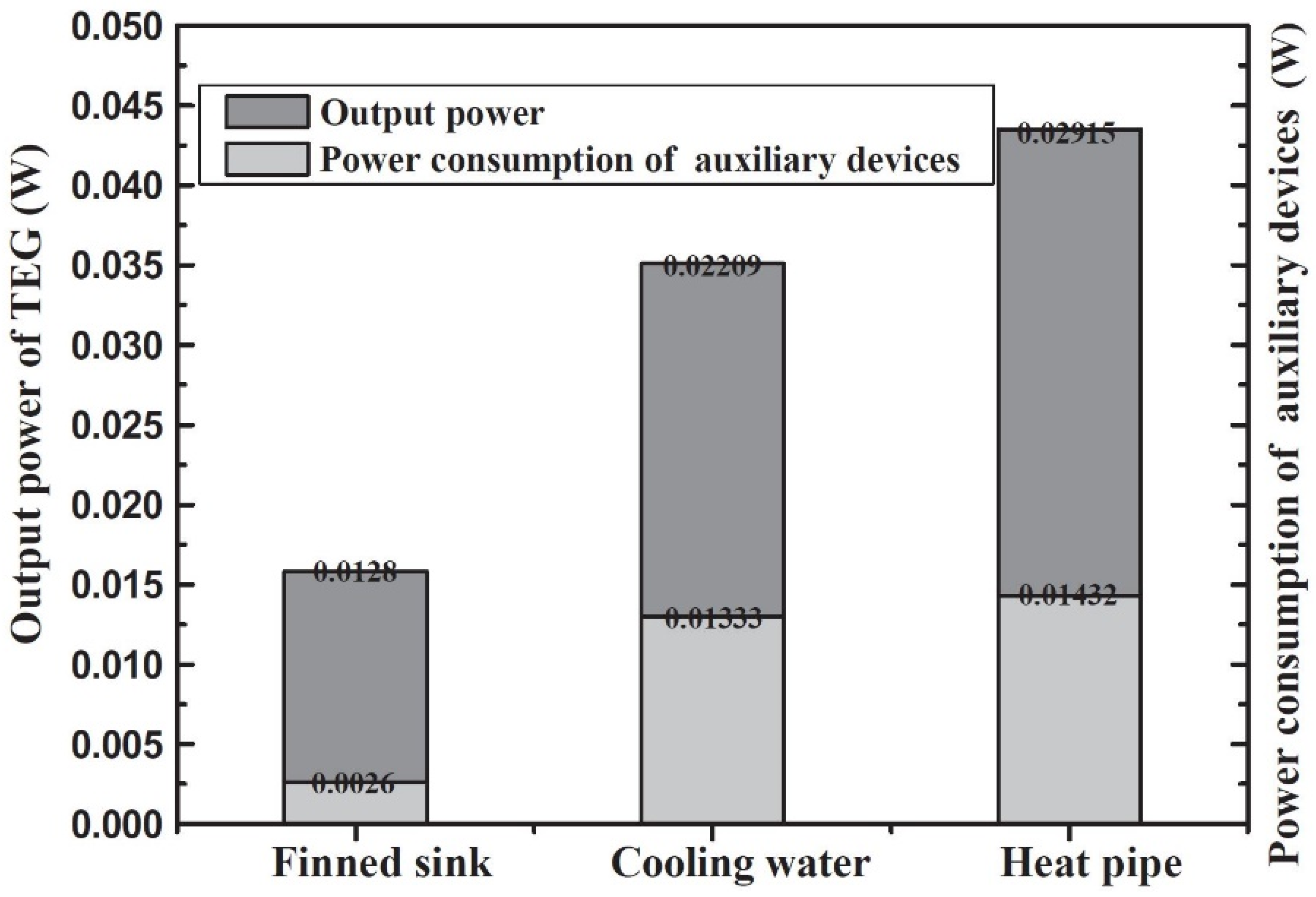
| [56] | experimental | heating plate | macrochannel | 3 × ZHUJIANG E. TGM-199-1.4-0.8 | 50 | 0.19 | 0.03542 = 0.02209 − 0.01333 | 37.63% |
| [57] | numerical | exhaust gas | macrochannel | 16 × Hi-Z HZ20 | 250 = 280 − 30 | 28.31 | 18.9 = 23.1 − 4.2 | 22.22% |
| [58] | num./exp. | exh. gas/hea. pl. | macrochannel | 8 × Bi2Te3 TEG | 131 = 180 − 49 | 4.25 | 4.14 = 4.215 − 0.075 | 1.81% |
| [62] | numerical | exhaust gas | macrochannel | 20 × Bi2Te3 TEG | 494 = 519 − 25 1 | 15.1 | 15.1 = 15.1 − 0.005 | 0.03% |
| with baffler | 20.3 | 20.3 = 20.3 − 0.005 | 0.02% | |||||
| [63] | numerical | exhaust gas | macrochannel | 144 × Marlow TG 12-8-01L | 185 = 200 − 15 1 | 1.6 | 1.28 = 1.56 − 0.28 | 21.88% |
| [64] | num./exp. | heating plate | macrochannel | - × Marlow DT12-6L | 235 = 250 − 15 1 | 59.1 | 41.63 = 51.25 − 9.62 2 | 23.11% |
| [67] | numerical | exhaust gas | macrochannel | 1400–12,000 × Marlow TG 12-8-01L | 170 = 187 − 17 1 | 1.72 | 1.16 2/1.91 = 2.13 − 0.22 | 11.52% |
| [68] | experimental | stove | macrochannel | 4 × Eur. Therm. GM250-241-10-12 | 250 = 295 − 45 | 10.4 | 2.4 = 10.4 − 8 | 333.33% |
| [70] | experimental | micro combust | macrochannel | 2 × Nipp. TEG1-127-30-30T250HP | 178 = 214 − 36 | 4.5 | 4.28 = 4.5 − 0.22 | 5.14% |
| [74] | numerical | hot surface | macrochannelmicrochannel | 1 × Bi2Te3 TEG | 252 = 277 − 25 | - - | −0.0002 −0.0048 | - - |
| [77] | experimental | heating plate | microchannel | 1 × Tellurex G2-56-0375 | 80 = 108 − 28 | 2.2 | 2.026 = 2.05 − 0.024 | 1.18% |
| [79] | numerical | hot surface | microchannel | 1 × Bi2Te3 TEG | 160 = 177 − 17 1 | 0.22 | 0.2207 = 0.2223 − 0.0016 | 0.72% |
| [80] | numerical | heating plate | microchannel | 1 × Bi2Te3 TEG | 80 = 107 − 27 | 0.6 | 0.52 = 0.54 − 0.02 2 | 3.92% |
| [82] | num./exp. | hot fluid | minichannel | 48 × Kryotherm TGM-199-1.4-1.15 | 155 = 175 − 20 1 | - | 4 3 | - |
| [83] | numerical | solar radiation | minichannel | 1 × Eur. Therm. GM200-71-14-16 | 176 = 199 − 23 | 3.87 | 0.724 = 0.724 − 0.00074 | 0.10% |
| [84] | experimental | hot fluid | microchannel | 1/2 × Bi2Te3 µTEG | 60 | - | 0.02 = 0.02 − 0.0015 3 | 7.50% |
| [85] | numerical | hot surface | microchannel | 1 × Poly-Si µTEG | 50 = 27 − (− 23) | 0.0009 | 46 × 10−9 = 71 × 10−9 − 25 × 10−9 | 54.35% |
| [93] | numerical | hot fluid | macrochannel | 1 × Bi2Te3 TEG | 80 = 100 − 20 1 | - | 15 | - |
| w. rotated fins | - | 20 | - | |||||
| [94] | experimental | hot fluid | macroch. w. fins | 100 × Marlow Ind. TG12-4 | 175 = 200 − 25 1 | - | 2 = 2.275 − 0.275 3 | 13.75% |
| [97] | experimental | hot fluid | macrochannel | 2 × TEP-1-142T300 | 165 = 188 − 23 1 | 3.85 | 3.85 3 | - |
| w. metal foam | 4.9 | 4.9 3 | - | |||||
| [98] | experimental | hot fluid | macro channel | 40 × Bi2Te3 | 70.6 1 | 0.90 | 0.87 = 0.9 − 0.03 | 3.45% |
| w. punched pan. | 1.22 | 0.98 = 1.1 − 0.12 | 12.24% |
Publisher’s Note: MDPI stays neutral with regard to jurisdictional claims in published maps and institutional affiliations. |
© 2021 by the authors. Licensee MDPI, Basel, Switzerland. This article is an open access article distributed under the terms and conditions of the Creative Commons Attribution (CC BY) license (https://creativecommons.org/licenses/by/4.0/).
Share and Cite
Pfeiffelmann, B.; Benim, A.C.; Joos, F. Water-Cooled Thermoelectric Generators for Improved Net Output Power: A Review. Energies 2021, 14, 8329. https://doi.org/10.3390/en14248329
Pfeiffelmann B, Benim AC, Joos F. Water-Cooled Thermoelectric Generators for Improved Net Output Power: A Review. Energies. 2021; 14(24):8329. https://doi.org/10.3390/en14248329
Chicago/Turabian StylePfeiffelmann, Björn, Ali Cemal Benim, and Franz Joos. 2021. "Water-Cooled Thermoelectric Generators for Improved Net Output Power: A Review" Energies 14, no. 24: 8329. https://doi.org/10.3390/en14248329