1. Introduction
The newly introduced different types of electrically driven systems in future more electric aircraft (MEA) significantly increase power demands, and thus increasing generation capacity requirements for the onboard electric power system (EPS) [
1,
2,
3,
4,
5]. Some specific loads with high dynamics such as flight actuation systems are characterized by significant power requirement peaks. These types of loads impose significant challenges for EPS rating definition and EPS stability and power quality [
1,
6]. To minimize these effects, the first option is to sufficiently increase the rated power of the onboard power generation system to handle these power peaks. This means the power generators should be sized based on the peak power rather than the average power, leading to a significant increase of EPS weight and volume. The second option is to keep generators sizing based on the average power consumption whilst implementing an energy storage system (ESS), that should be sized to smooth these high power peaks, i.e., to supply the high dynamic transient loads such that these become invisible for the generators. Implementation of the ESS in this way allows enhancing the design of the MEA EPS by reducing the sizing of the power generators, as well as adding the capability of storing the regenerative energy produced by some of the loads like the electromechanical actuator (EMA) for future re-use instead of dissipating it in braking resistors. In addition, smoothing of the power demand surges seen by generators lead to reduced power cables size following the average power consumption rather than its peak power/current requirement, which results in further reduction of EPS weight.
A wide range of ESSs is available in the market with different characteristics for different applications [
7,
8]. Aircraft applications impose design constraints for the weight of onboard equipment to minimize fuel consumption. Accordingly, the ESS needs to fulfill its required power and energy ratings at minimum weight. This makes the electrochemical ESS a better choice for aircraft EPS. There are two representative devices, which are the lithium-ion batteries that are characterized by high specific energy (100–300 Wh/kg), and supercapacitors (SC) that that characterized by high specific power (20 kW/kg) at low specific energy (5–10 Wh/kg) [
9]. Accordingly, the ESS selection depends on the specific requirements of the applications. For centralized ESS where a central energy storage unit supplies all the targeted loads, and thus requires large energy capacity ESS, the use of Li-ion batteries is more adequate. In contrast, distributed ESSs where distributed energy storage units are localized at each load, and thus do not require high energy capacity but need significant power capability to cover the short-term peak power demands; therefore, in these, the use of SC is more adequate [
10]. Much research has been focused on the utilization of the SC-based ESS for aircraft EPS and its corresponding benefits; however, most of the research is focused on studying the energy management strategies [
6,
11,
12,
13] rather than studying the design optimization for the SC-ESS itself, including its associated management subsystems in terms of ESS weight and reliability, which are very important parameters for aircraft applications.
In the paper, the design and implementation of SC-based ESS and associated management subsystems for SC cells’ voltage monitoring, balancing, and overvoltage protection are proposed.
The paper is organized into five sections. In
Section 2, the sizing and optimal design of the SC energy storage system are investigated. In
Section 3, The design of cells’ voltage monitoring and overvoltage protection subsystem is presented. In
Section 4, an experimental evaluation of the proposed system is presented, and
Section 5 summarizes the conclusions of this work.
2. Sizing of the SC Energy Storage System
The supercapacitor energy storage system (SC-ESS) as shown in
Figure 1 should be interfaced to the DC power bus through a DC/DC converter that controls the SC-ESS charge/discharge process. The SC-ESS is constructed based on series/parallel combinations of SC cells to achieve the required voltage level and energy capacity. The SC-ESS presented in this paper is designed to fulfill the energy and power requirements listed in
Table 1 based on the power consumption of an EMA load profile in an aircraft. Accordingly, the equivalent capacitance of the SC-ESS can be estimated based on these requirements as [
14]:
where
Estr is the targeted energy capacity of the SC-ESS whilst
Vmax and
Vmin are its targeted maximum and minimum operating voltages, respectively. Accordingly, the selected minimum and maximum voltages strongly affect the SC-ESS sizing to achieve the required energy capacity (
Estr).
The common design technique is selecting the SC-ESS maximum voltage at a value close to the DC bus voltage whilst keeping its minimum voltage around 50% of that value to limit the current ratings of both the SC-ESS and the interfaced DC/DC converter, as this impacts the size/weight of their magnetics/semiconductors. Accordingly, by setting the minimum and maximum SC-ESS voltages, the capacitance of the single SC cell in the string, which consists of n series-connected cells, can be estimated as follows:
where
Vcell-max is the maximum operating voltage of the single SC cell (2.7 V for most SC cells). This capacitance can be obtained directly using a single cell or by implementing a parallel combination of two or more cells based on the available standard capacitances.
Applying the SC-ESS design requirements listed in
Table 1 to Equations (1) and (2) and selecting
Vmax = 260 V and
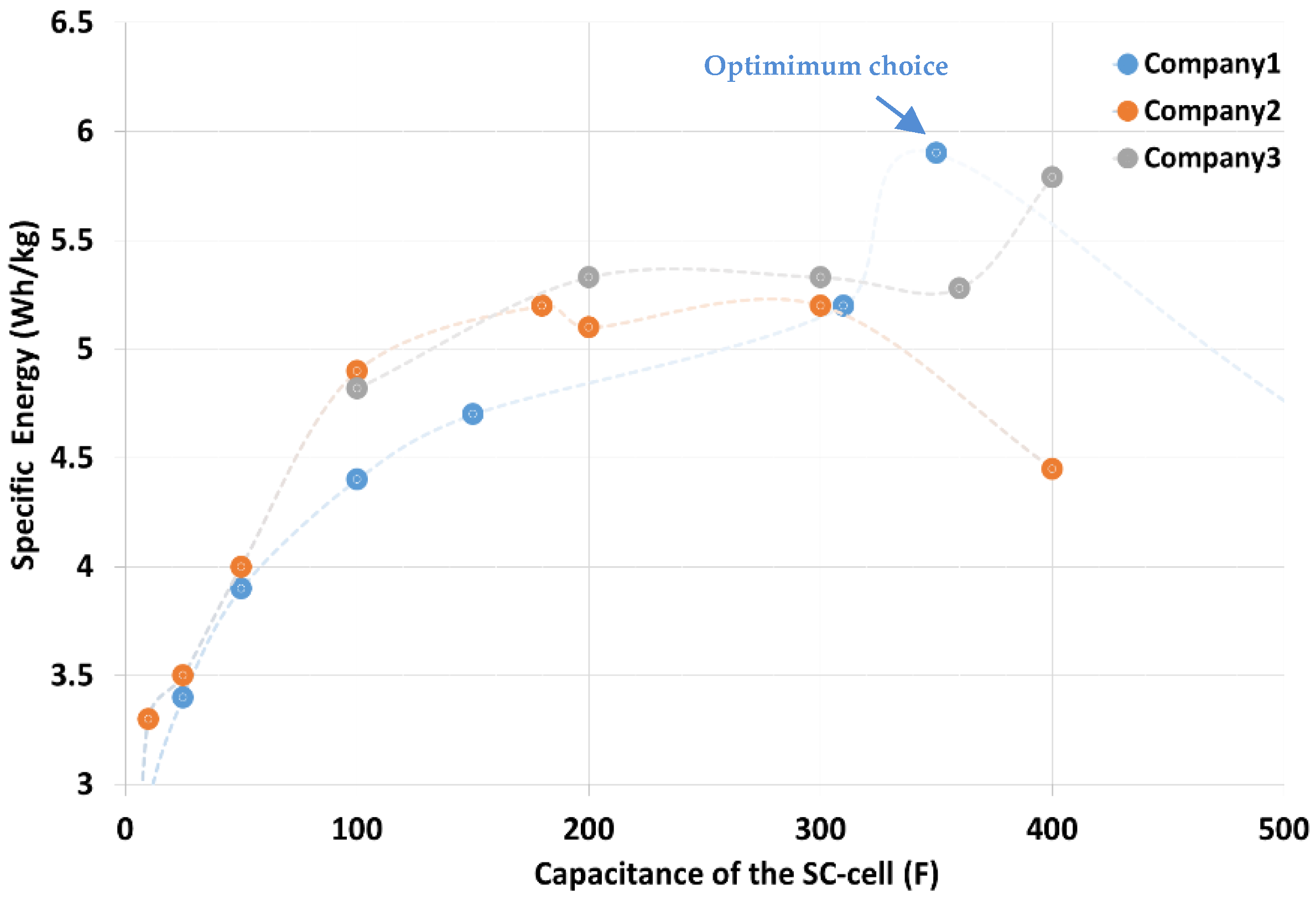
Vcell-max = 2.5 V, yield the required capacity of the single SC cell to be around 150 F. However, changing the targeted SC-ESS operating voltage range can enable utilization of other cells with higher/lower capacities that might have different characteristics and, hence, make a choice based on the best cell. Accordingly, to identify the best SC cell to be implemented to achieve minimum overall weight for the SC-ESS, the characteristics of the different commercially available SC cells in the range of 100–400 F have been evaluated focusing on their specific energy (Wh/kg) as it significantly affects the overall SC-ESS weight.
Figure 2 shows the specific energy of the different SC cells within the selected range. As can be seen, the 150 F SC cell that matches the design calculations at
Vmax = 260 V has lower specific energy (4.7 Wh/kg) compared to the 350 F cell produced by Company1, which has 25% more specific energy (5.9 Wh/kg). Accordingly, implementing this cell in the targeted SC-ESS resulted in a 25% reduction in the overall SC cells weight. However, implementing such large capacity cells requires a reduction of
Vmax according to (1) and (2), which adds the advantages of reducing the number of series-connected cells and thus reducing the complexity of cells’ voltage monitoring and overvoltage protection subsystem. In the meantime, it also adds the disadvantage of increasing the current rating of the interfaced DC/DC converter, thus increasing its size and weight.
The two design options (based on 150 F and 350 F cells) are investigated based on the specifications of the targeted SC-ESS listed in
Table 2 and the design parameters for designs are presented. As it can be seen, design B, which utilizes the 350 F SC cell, has reduced weight by nearly 22% compared to design A. However, the maximum current required to deliver the given power (2 kW) at minimum voltage is increased significantly and this may increase the thermal stress of the SC-ESS and increase the weight/size of the interfaced converter. As per the investigations done in [
15,
16], implementing a two-channel interleaved converter in conjunction with wide band-gap semiconductor switches can minimize the effects of the increased current rating on the converter size/weight. Additionally, the investigations carried out in [
15] show minor differences in terms of thermal stresses between the two cells due to the better thermal characteristics and reduced internal resistance of the 350 F SC cell.
3. SC Cells’ Voltage Monitoring and Overvoltage Protection Subsystem
Based on the proven weight savings in the targeted SC-ESS according to design B that utilizes 350 F SC cells, this design is considered for the SC-ESS and its associated subsystems are presented in this paper. To facilitate the design, manufacturing, and maintenance of the SC-ESS, a modular distributed architecture has been considered such that the targeted system is based on four series-connected modules, each of these consisting of 12 series-connected SC cells with associated voltage monitoring and overvoltage protection circuits, as presented in the following subsections.
3.1. SC Cells’ Voltage Monitoring Subsystem
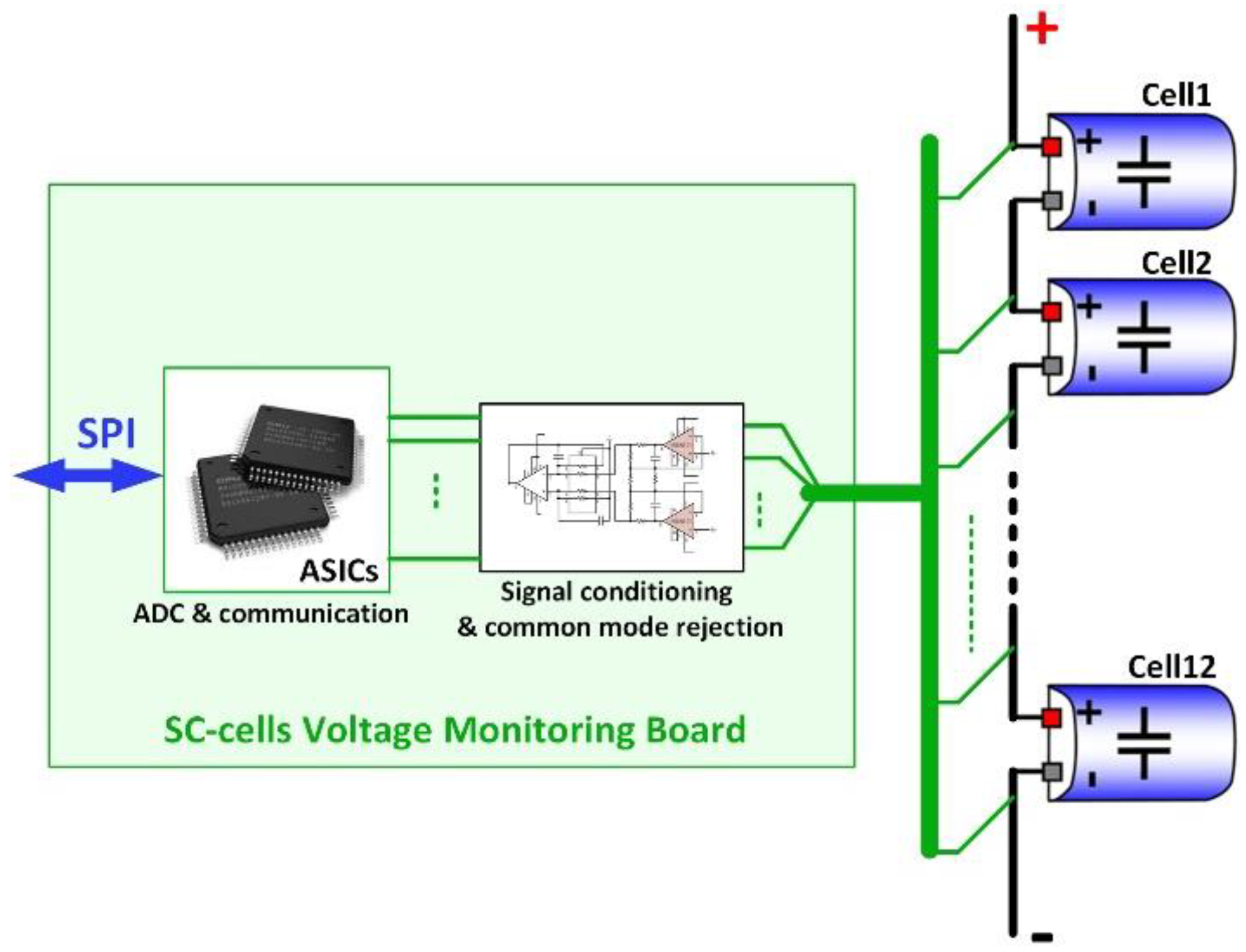
Monitoring the voltages of the SC cells is essential to ensure safe SC-ESS operation, as well as assessing the cells’ state of charge (SoC) and state of health (SoH). To monitor all 48 cells with a minimum wirings/complexity, a distributed cells’ voltage monitoring subsystem is implemented such that each module has a localized cells’ voltage monitoring board and all the boards alongside the modules are sharing the data via a communication channel which selected to be based on serial peripheral interface (SPI) protocol. The module’s voltage monitoring board as illustrated in
Figure 3 consists of signal conditioning electronics with associated filtration for adaptation of the measured signals to a suitable level, and some application-specific integrated circuits (ASICs) for analog to digital conversion (ADC) and communication protocols.
3.2. SC Cells’ Overvoltage Protection Subsystem
The maximum operating voltage of the SC cells should be strictly limited at the recommended level by the manufacturer as exceeding this limit may result in a catastrophic failure of the cell. Accordingly, an overvoltage protection subsystem is mandatory to ensure SC-ESS safe operation. Overvoltage protection of the cells can be achieved by either preventive or corrective actions. Overvoltage protection subsystems based on preventive action are employing one of the cells’ voltages active or passive voltage balancing techniques [
17,
18,
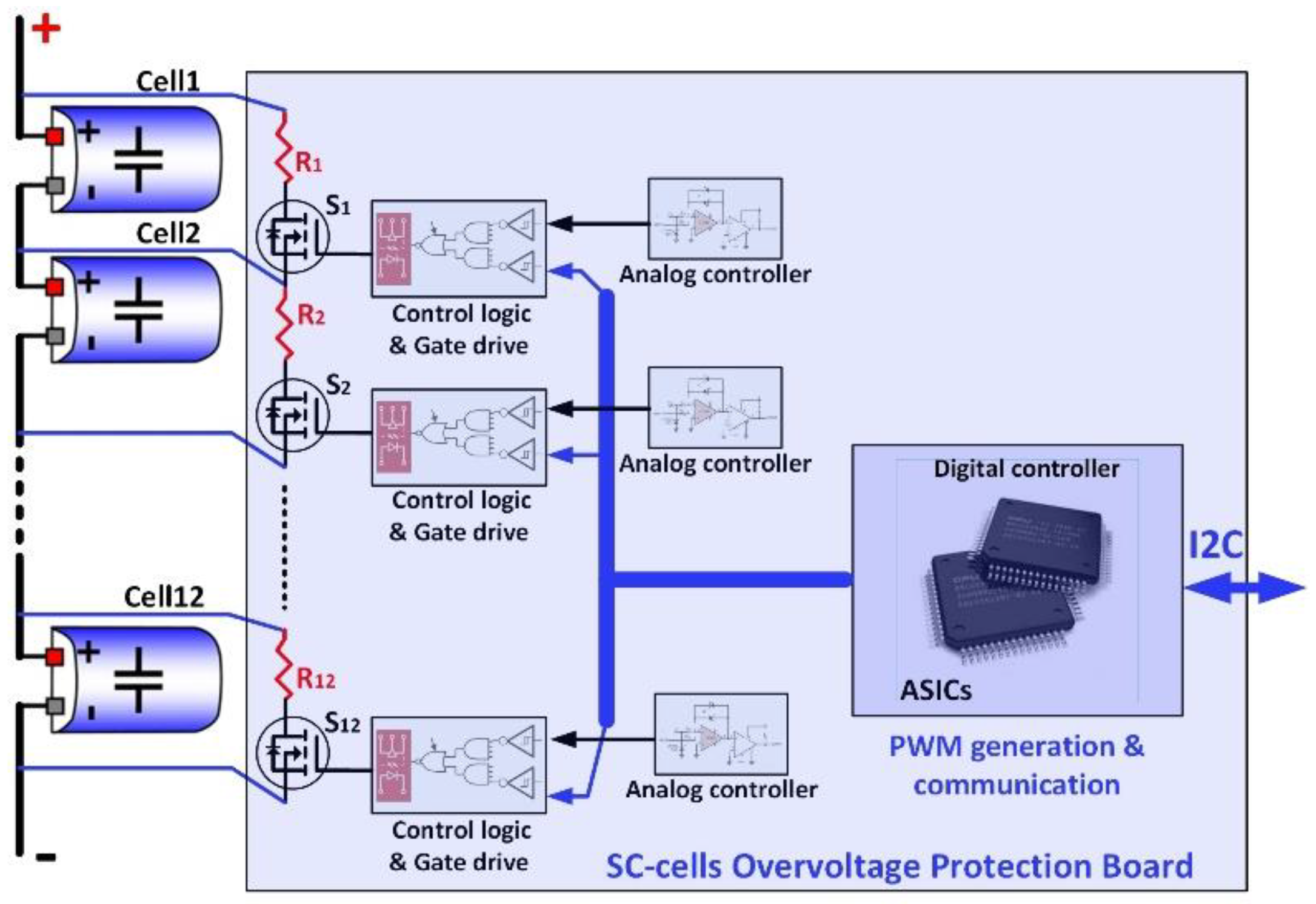
19] that act during the charging process to prevent the weak cells within the string from reaching the maximum voltage limit whilst other stronger cells are still charging. On the other hand, overvoltage protection subsystems based on corrective action are employing shunt circuits that act only if one or more cells hit the maximum voltage limit during the charging process to completely bypass those cells preventing them from further charging whilst allowing other cells within the string to continue charging. The overvoltage protection (OVP) in the proposed SC-ESS design is built to allow both preventive and corrective actions to ensure maximum reliability for the OVP subsystem. The block diagram shown in
Figure 4 represents the different parts of the proposed OVP subsystem.
The subsystem consists of a shunt circuit per cell, formed by a semiconductor switch (Si) and a power resistor (Ri), which is controlled by two independent controllers: the first controller is built based on a voltage comparator with associated filtering and signal conditioning electronics. Each SC cell has its controller that works independently from other cells’ controllers or system central controller and activates the shunt circuit of the cell automatically once the cell voltage hits the preset limit; hence, it performs the corrective actions of the OVP subsystem. The second controller is built based on a digital platform that implements digital electronics (ASICs) that receives commands via the inter-integrated circuit I2C communication channel from the central controller. Each SC module has its digital controller that controls the shunt circuits of the entire cells based on pulse width modulation (PWM) with different duty cycles defined by the central controller according to the degree of mismatching between measured cells’ voltages to perform cells’ voltage balancing as a preventive action for overvoltage protection.
The resistance of the shunt resistor should be selected based on the level of degradation/capacity fade of the SC cells to be mitigated. Under the specified constant charging power (2 kW), the current of the SC-ESS decreases as the voltage increases with the increase in the SoC. Accordingly, the value of the current at which the degraded SC cell hits the maximum voltage limit (2.5 V) is changing according to the level of its capacity fading (as a percentage of the initial capacitance), as illustrated in
Figure 5. As it can be seen, with no capacity fade in the SC cells, all the cells hit the limit when the voltage of the SC-ESS reaches 120 V (100% SoC), where the current of the SC-ESS is 16.7 A, and hence, no actions are required from the OVP subsystem, since charging is going to be stopped anyway. On the other hand, introducing 10% capacity to one or more cells causes the voltage of these specific cells to hit the limit early whilst the voltage of the SC-ESS is still at around 108 V. Continuing the charging process under this condition forces the OVP subsystem to bypass degraded cells by activating their corresponding shunt circuits. The current of the SC-ESS at this condition is around 18.6 A; hence, the shunt circuit associated with the cell should be able to handle the full value of this current/power. For the proposed SC-ESS, the shunt resistor is selected to be 100 mΩ to allow a shunt current of 25 A at maximum cell voltage limit (2.5 V). This allows mitigating the capacity fade of ≈33%, as illustrated in
Figure 5.
The preventive action of the OVP subsystem does not affect the sizing of the shunt circuit as the balancing mechanism should operate with a significantly lower power compared to the protective action. Hence, sizing of the shunt circuit based on protective action supports both protective and preventive actions. Accordingly, the balancing act can operate with continuous current (defined by cell voltage and the resistance of the shunt circuit) for fast balancing, or with PWM current for slower operations, which gives more flexibility to design the balancing algorithms.
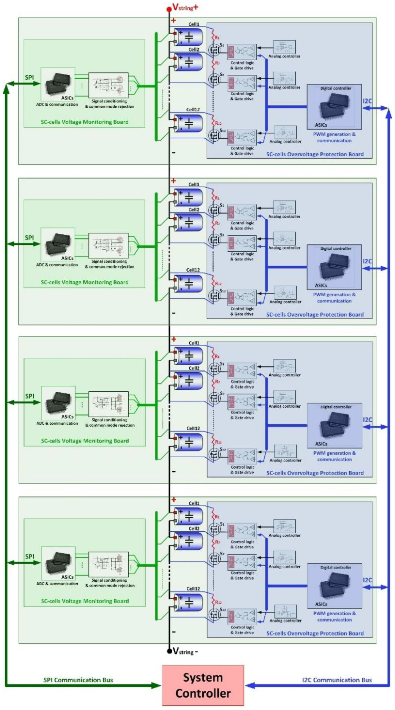
The block diagram of the developed SC-ESS with all subsystems is shown in
Figure 6. The full system consists of four series-connected modules, each with a power board (connecting SC cells) and two detachable boards for voltage monitoring and OVP as can be seen in
Figure 7. The aluminum enclosure of the module is used as a heat sink for the shunt resistors for more savings in weight.
4. Experimental Validations
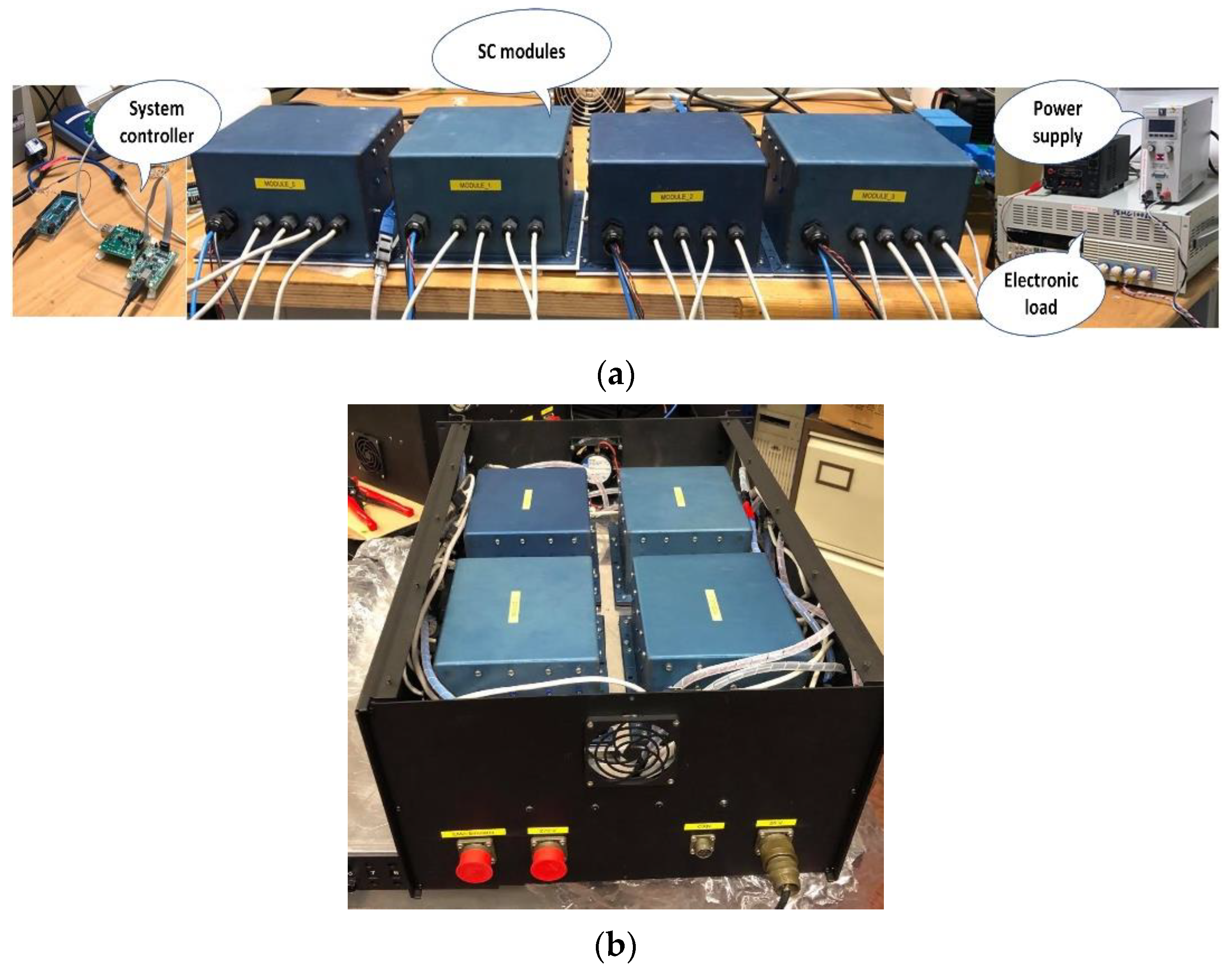
To validate the proposed SC-ESS design, a test setup based on the manufactured four modules has been constructed. The test setup as shown in
Figure 8 consists of a power supply that acts as a charger, the electronic load that acts as the system load, and the Arduino Mega 2560 board that acts as the SC-ESS controller. The Arduino board is interfaced with the PC to perform data-logging as well.
The evaluation of the proposed SC-ESS design with associated management electronics is achieved by three tests as detailed below.
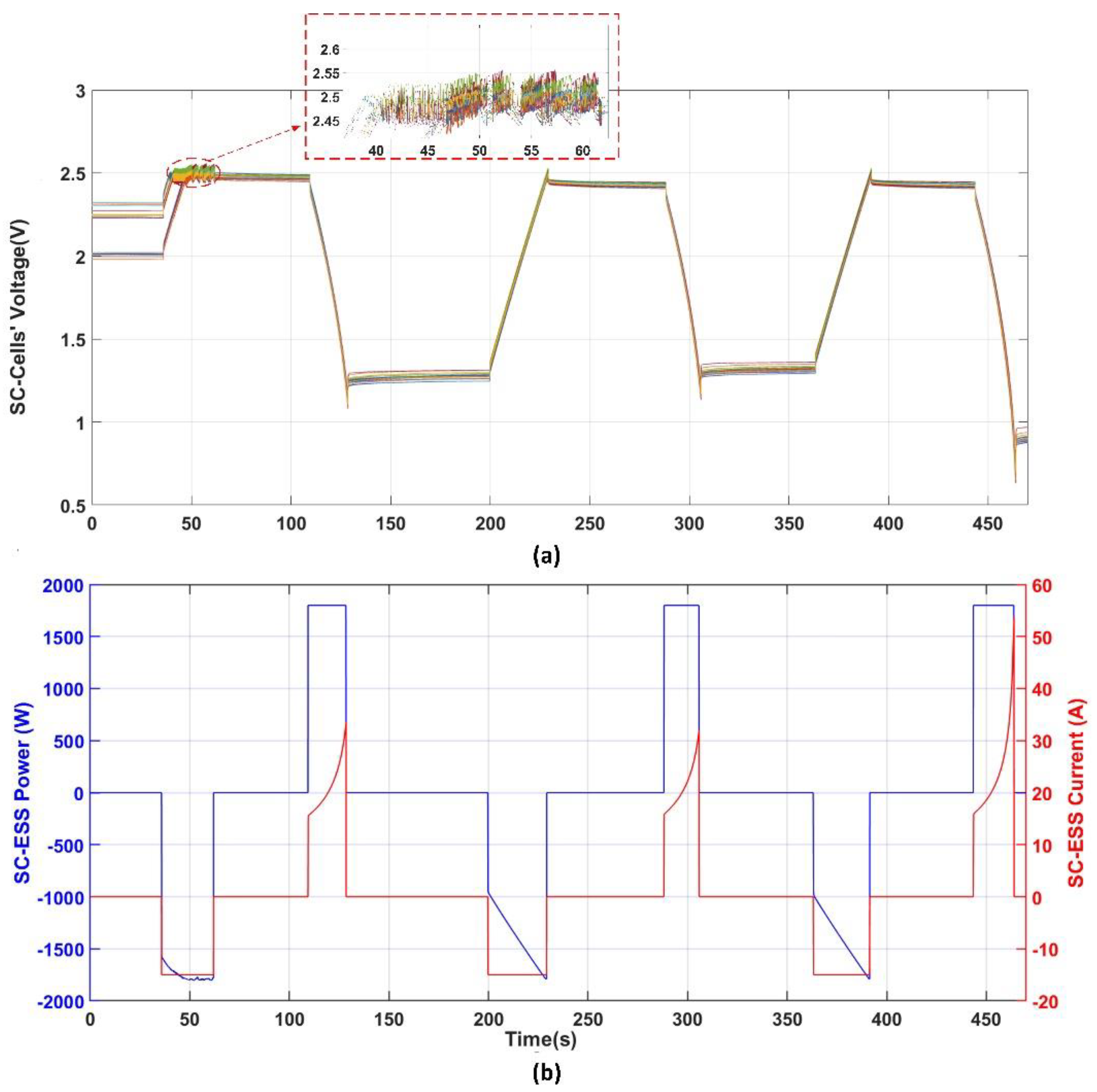
The first test is reported in
Figure 9, in which the operation and performance of the protective action of the OVP subsystem are evaluated. It is conducted under continuous charge–rest–discharge cycling with 15 A constant current charge and 1.8 kW constant power discharge whilst voltages of the SC cells are measured by the voltage monitoring subsystem and the stack current (SC-ESS current) are measured by a current prob. The test started with forced voltages mismatches between the SC cells of 0.25 V to emulate a capacity mismatch of 12.5%, which caused the cells that were initially at higher voltages to hit the maximum voltage limit (2.5 V) at t = 38 s, and hence the OVP subsystem activated the shunt circuits associated with those cells. Accordingly, their voltages were kept at the limit whilst other cells continued charging until they hit the limit as well (at t = 47 s in this experiment) and the shunt circuits for these cells were also activated to maintain their voltages at the limit until the charging process stopped (at t = 62 s). The overshoots of cell voltage due to the switching of the shunt circuit were maintained at ≤10 mV to ensure the maximum utilization of cells’ capacity. Hence, the test confirmed that the OVP subsystem enabled safe operation for SC-ESS that was able to complete the charge cycles and protect the SC cells that were at the risk of overvoltage under the imposed voltages mismatching that emulates SC cell capacity fade due to degradation.
The second test, which is reported in
Figure 10, evaluates the operation of the OVP subsystem under given discharging commands from the central controller to demonstrate its ability to execute these commands when required. These may happen under some conditions like a safe discharge of the ESS. The test starts with SC cells having unequal voltages, and because of applying multiple charging cycles (at t = 49 s and 130 s) with a current of 15 A, the voltage raises to the overvoltage limit; hence, activation of the associated shunt circuits by the OVP preventive action was required at t = 160 s, which continued in operation until the charging cycle stopped at t = 172 s. Accordingly, as the shunt resistors were thermally coupled with the modules’ enclosures, the power dissipated in these resistors causes temperatures (temp.) of the SC-modules’ enclosures to be increased, as can be seen for modules 1 and 2 recorded temps. (M1 and M2 case temp.) in
Figure 10. At t = 360 s, a controlled discharge for the cells of modules 1 and 3 with a duty cycle of 20% followed by faster discharging with larger duty cycles (50% and 75%) based on the received commands from the central controller were reported. Accordingly, the energy stored in these modules dissipated in the shunt circuits, causing temp. increase, as can be seen for M1 case temp. recorded. When the voltage reached 0.4 V, the discharge was stopped. At t = 580 s, the remaining cells at modules 2 and 4 were also commanded to discharge with a 75% duty cycle and this caused a fast discharge to the same minimum cell voltage as the other cells (0.4 V) to achieve a balanced state for all cells while the energy dissipated in these modules also caused its temp. to be increased, as can be seen for M2 case temp. recorded. This test confirmed the capability of the OVP subsystem to perform a discharge cycle for specific SC cells by a specific discharging rate controlled by the duty cycle that is selected by the central controller and commanded via the communication bus.
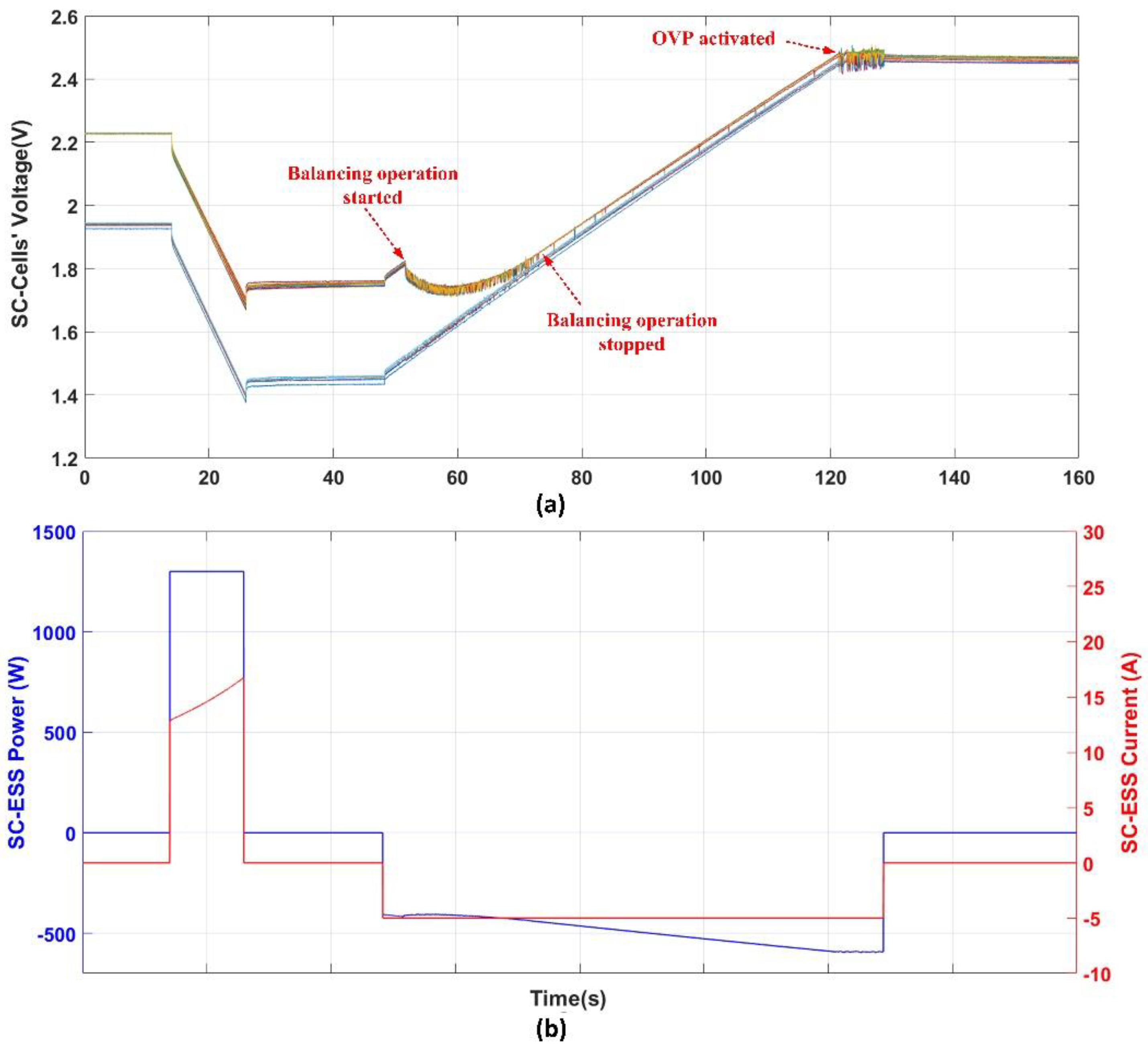
The third test reported in
Figure 11 evaluates the capability of the OVP subsystem to perform active dissipative SC cells’ voltage balancing as a preventive action to protect the cells from overvoltage. The test started with imposed mismatching between the SC cells, then a discharging process by a constant power of 1.3 kW was introduced at t = 15 until t = 25 s to allow for sufficient charging time for demonstrating the balancing mechanism. After a rest time provided to the system, the charging of the SC-ESS started by a constant current of 5 A at t = 47 s, where the mismatching in the SC cells’ voltages was detected by the system controller. Following this, it activates the balancing mechanism in which the SC cells’ shunt circuits equalize the cells’ voltages in a PWM manner. As can be seen, the balancing mechanism succeeded to achieve balanced cells’ voltages in a considerable short time due to the ability of the shunt circuit to handle a high current.
In the three experimental tests, the results confirmed the proposed functionalities of the SC-ESS in terms of cells’ voltage monitoring, fast balancing, and overvoltage protection.
5. Conclusions
In this paper, the design and implementation of a smart super-capacitors-based energy storage system are proposed. The SC-ESS sizing was optimized for minimum weight by utilizing the highest energy density cells of the available range and adjusting the operating voltage range, accordingly. In addition, the proposed design minimizes the wirings for cells’ voltage monitoring and overvoltage protections by employing a distributed modular architecture coordinated via standard communication buses. SC cells overvoltage protection subsystem in the proposed design implements two independent preventive and protective actions for the highest reliability to ensure safe operation of the system. Finally, the design is validated based on experimental testing of the manufactured modules and the results showed the achievement of the proposed functionalities.
Author Contributions
Conceptualization, A.M.F., M.R. and C.K.; methodology, A.M.F.; software, A.M.F. and M.K.; validation, A.M.F.; formal analysis, A.M.F., M.R. and C.K.; investigation, A.M.F. and C.K.; resources, S.B. and C.K.; data curation, A.M.F.; writing—original draft preparation, A.M.F.; writing—review and editing, A.M.F., C.K. and S.B.; visualization, A.M.F.; supervision, C.K. and S.B.; funding acquisition, S.B. All authors have read and agreed to the published version of the manuscript.
Funding
The project received funding from the Clean Sky 2 Joint Undertaking under the European Union’s Horizon 2020 research and innovation program under grant agreement No 755485.
Institutional Review Board Statement
Not applicable.
Informed Consent Statement
Not applicable.
Data Availability Statement
Not applicable.
Conflicts of Interest
The authors declare no conflict of interest. The funders had no role in the design of the study; in the collection, analyses, or interpretation of data; in the writing of the manuscript, or in the decision to publish the results.
References
- Buticchi, G.; Bozhko, S.; Liserre, M.; Wheeler, P.; Al-Haddad, K. On-Board Microgrids for the More Electric Aircraft—Technology Review. IEEE Trans. Ind. Electron. 2019, 66, 5588–5599. [Google Scholar] [CrossRef] [Green Version]
- Wheeler, P.; Bozhko, S. The More Electric Aircraft: Technology and challenges. IEEE Electrif. Mag. 2014, 2, 6–12. [Google Scholar] [CrossRef]
- Lamantia, A.; Giuliani, F.; Castellazzi, A. Power Scalable Bi-Directional DC-DC Conversion Solutions for Future Aircraft Applications. Energies 2020, 13, 5470. [Google Scholar] [CrossRef]
- Ojeda-Rodríguez, Á.; González-Vizuete, P.; Bernal-Méndez, J.; Martín-Prats, M.A. A Survey on Bidirectional DC/DC Power Converter Topologies for the Future Hybrid and All Electric Aircrafts. Energies 2020, 13, 4883. [Google Scholar] [CrossRef]
- Rigogiannis, N.; Voglitsis, D.; Jappe, T.; Papanikolaou, N. Voltage Transients Mitigation in the DC Distribution Network of More/All Electric Aircrafts. Energies 2020, 13, 4123. [Google Scholar] [CrossRef]
- Todd, R.; Wu, D.; Girio, J.A.d.S.; Poucand, M.; Forsyth, A.J. Supercapacitor-based energy management for future aircraft systems. In Proceedings of the 2010 Twenty-Fifth Annual IEEE Applied Power Electronics Conference and Exposition (APEC), Palm Springs, CA, USA, 21–25 February 2010; pp. 1306–1312. [Google Scholar]
- Nadeem, F.; Hussain, S.M.S.; Tiwari, P.K.; Goswami, A.K.; Ustun, T.S. Comparative Review of Energy Storage Systems, Their Roles, and Impacts on Future Power Systems. IEEE Access 2019, 7, 4555–4585. [Google Scholar] [CrossRef]
- Al Shaqsi, A.Z.; Sopian, K.; Al-Hinai, A. Review of energy storage services, applications, limitations, and benefits. Energy Rep. 2020, 6, 288–306. [Google Scholar] [CrossRef]
- Zuo, W.; Li, R.; Zhou, C.; Li, Y.; Xia, J.; Liu, J. Battery-Supercapacitor Hybrid Devices: Recent Progress and Future Prospects. Adv. Sci. 2017, 4, 1600539. [Google Scholar] [CrossRef] [PubMed]
- Mohamed Rashed, C.K. Design and evaluation of an energy storage system for helicopters. In Proceedings of the 9th International Conference on Power Electronics, Machines and Drives, Liverpool, UK, 17–19 April 2018. [Google Scholar]
- Chen, J.; Song, Q. A Decentralized Energy Management Strategy for a Fuel Cell/Supercapacitor-Based Auxiliary Power Unit of a More Electric Aircraft. IEEE Trans. Ind. Electron. 2019, 66, 5736–5747. [Google Scholar] [CrossRef]
- Chen, J.; Song, Q.; Yin, S.; Chen, J. On the Decentralized Energy Management Strategy for the All-Electric APU of Future More Electric Aircraft Composed of Multiple Fuel Cells and Supercapacitors. IEEE Trans. Ind. Electron. 2020, 67, 6183–6194. [Google Scholar] [CrossRef]
- Saenger, P.; Devillers, N.; Deschinkel, K.; Péra, M.; Couturier, R.; Gustin, F. Optimization of Electrical Energy Storage System Sizing for an Accurate Energy Management in an Aircraft. IEEE Trans. Veh. Technol. 2017, 66, 5572–5583. [Google Scholar] [CrossRef]
- Navarro, G.; Blanco, M.; Torres, J.; Nájera, J.; Santiago, Á.; Santos-Herran, M.; Ramírez, D.; Lafoz, M. Dimensioning Methodology of an Energy Storage System Based on Supercapacitors for Grid Code Compliance of a Wave Power Plant. Energies 2021, 14, 985. [Google Scholar] [CrossRef]
- Fares, A.; Klumpner, C.; Rashed, M. Design Considerations to Optimise Supercapacitor-based Energy Storage Systems for Aerospace Applications. In Proceedings of the 2018 IEEE International Conference on Electrical Systems for Aircraft, Railway, Ship Propulsion and Road Vehicles & International Transportation Electrification Conference (ESARS-ITEC), Nottingham, UK, 7–9 November 2018; pp. 1–8. [Google Scholar]
- Fritz, N.; Rashed, M.; Klumpner, C. Power Density Optimization of a DC/DC Converter for an Aircraft Supercapacitors Energy Storage. In Proceedings of the 2018 IEEE International Conference on Electrical Systems for Aircraft, Railway, Ship Propulsion and Road Vehicles & International Transportation Electrification Conference (ESARS-ITEC), Nottingham, UK, 7–9 November 2018; pp. 1–9. [Google Scholar]
- Ibanez, F.M. Analyzing the Need for a Balancing System in Supercapacitor Energy Storage Systems. IEEE Trans. Power Electron. 2018, 33, 2162–2171. [Google Scholar] [CrossRef]
- Guo, M.; Zhang, X.; Li, H.; Liao, H.; Liao, Y.; Meng, Z.; Zhang, H.; Huang, Z. Cooperative Cell Balancing of Supercapacitors with Adaptive Observers. In Proceedings of the 2020 IEEE Energy Conversion Congress and Exposition (ECCE), Detroit, MI, USA, 11–15 October 2020; pp. 588–593. [Google Scholar]
- Wang, X.; Cheng, K.W.; Fong, Y.C. Non-Equal Voltage Cell Balancing for Battery and Super-Capacitor Source Package Management System Using Tapped Inductor Techniques. Energies 2018, 11, 1037. [Google Scholar] [CrossRef] [Green Version]
| Publisher’s Note: MDPI stays neutral with regard to jurisdictional claims in published maps and institutional affiliations. |
© 2021 by the authors. Licensee MDPI, Basel, Switzerland. This article is an open access article distributed under the terms and conditions of the Creative Commons Attribution (CC BY) license (https://creativecommons.org/licenses/by/4.0/).


 ,
, 


