Article

Energy-Efficient and Disjoint Multipath Using Face Routing in Wireless Sensor Networks

1
Research Institute for Computer and Information Communication, Chungbuk National University, Cheongju 28644, Korea
2
Division of Computer Science and Engineering, Kongju National University, Cheonan 31080, Korea
3
School of Information and Communications Engineering, Chungbuk National University, Cheongju 28644, Korea
*
Author to whom correspondence should be addressed.
Energies 2021, 14(22), 7823; https://doi.org/10.3390/en14227823
Submission received: 11 October 2021 / Revised: 6 November 2021 / Accepted: 18 November 2021 / Published: 22 November 2021
(This article belongs to the Special Issue Green Network Technologies and Renewable Energy Systems)

Abstract

:
In WSNs, multipath is well-known as a method to improve the reliability of packet delivery by making multiple routes from a source node to a destination node. To improve reliability and load-balancing, it is important to ensure that disjoint characteristics of multipath do not use same nodes during path generation. However, when multipath studies encounter a hole area from which is hard to transmit data packets, they have a problem with breaking the disjoint features of multipath. Although existing studies propose various strategies to bypass hole areas, they have side effects that significantly accelerate energy consumption and packet transmission delay. Therefore, to retain the disjoint feature of multipath, we propose a new scheme that can reduce delay and energy consumption for a node near a hole area using two approaches—global joint avoidance and local avoidance. This scheme uses global joint avoidance to generate a new path centered on a hole area and effectively bypasses the hole area. This scheme also uses local joint avoidance that does not select the same nodes during new path generation using a marking process. In simulations, the proposed scheme has an average 30% improvement in terms of average energy consumption and delay time compared to other studies.

1. Introduction

Wireless Sensor Networks (WSNs) exploit millions of sensor devices that collect sensing data from their sensors and transmit these data to a sink for analysis [1,2,3,4,5,6,7]. WSNs do not use all network topology information, but exploit local information in the one-hop range due to the characteristics of sensor devices with limited resources. Since WSNs have features such as random deployment with numerous small sensors, the price of each sensor must be cheap, and this creates a resource limitation in performance. Because of the limited resources of sensors in WSNs, many researchers have tried to increase the reliability of data transmission. Among various research on reliability, WSN researchers have paid particular attention to multipath studies, since these studies can improve transmission reliability in WSNs [5,8,9,10,11]. Multipath research in WSNs uses various strategies to improve the reliability of transmission from a source node to a destination, i.e., multipath research tries to improve reliability using several perspectives, such as path redundancy, which provides opportunities to deliver packets to a network gateway, and load-balancing for data traffic over a network. Among several multipath research issues, one of the important multipath research issues is a disjoint characteristic that maintains the spacing between multiple generated paths [12,13,14,15,16,17]. The so-called disjoint multipath means that this multipath does not exploit the same nodes or links as other generated multipaths. If the same nodes or the same links are redundant when a WSN generates a new multipath, this accelerates the energy depletion of redundant nodes. When node energy is exhausted, the multipath connection is damaged, causing path failure. By maintaining the disjoint feature of multipath, WSNs can prevent path failure, therefore improving the reliability of multipath research.
In addition, the disjoint characteristic of multipath requires one more consideration, which is the hole area. In WSNs, a hole area means a region where sensors are not present or communication between sensors is impossible due to noise or interference. Due to the WSN characteristic that sensor nodes are randomly placed in a very large area, this is a traditional WSN problem because the sensors are located densely or sparsely in some areas [5,18,19,20,21]. In WSN, when a node encounters a hole area during multipath generation through a geographic routing, this results in breaking its disjoint feature. Geographic routing generally searches for candidate nodes using greedy forwarding that transmits data packets to neighbor nodes close to a destination node within one-hop range [22,23,24,25,26,27]. When a current node does not find candidate nodes of geographic routing, it uses face routing, which is a famous recovery strategy mode in geographic routing. When this node exploits face routing, it generates a particular local graph within one-hop range and then transmits data packets to the searched candidate nodes according to a determined searching direction. Since face routing exploits a maze escape method that reaches an exit by continuing to move in a selected direction in the maze, this node searches the candidate nodes in a determined routing direction in the generated local graphs. However, in multipath generation, when a node encounters a hole area, all multipaths overlap using the same path around a hole area due to a face routing scheme [16]. Although this situation transmits data packets to a destination by detouring a hole area, it has a path overlap problem that destroys the disjoint feature of multipath in a hole area. In this situation, if the overlapping path is damaged, there is no replacement path, and it causes a decrease in reliability for packet transmission, and also accelerates energy consumption because this situation repeatedly uses the same nodes in overlapping paths.
To solve this problem, multipath research maintains the disjoint feature using additional methods in hole areas. One of the multipath studies that avoids the hole area is the robust disjoint multipath routing scheme (RDM), which undertakes hole modeling to avoid hole areas [16,17]. However, due to hole modeling, RDM requires a lot of overhead from the sensor nodes, which have limited resources. In addition, since the hole size can change, nodes that exist at the hole boundary should repeatedly inform the hole area, and this causes additional energy consumption for resource-limited sensor nodes. As the overhead of a sensor node increases, energy depletion is accelerated, risking the generation of a new hole area.
To handle this limitation, an energy-efficient and disjointed multipath for void-handling (EEDMVH) maintains the disjoint feature of the multipath using face routing around the hole area when generating new multipaths [28]. EEDMVH does not use the used nodes when it creates the new paths, using a marking process to signify the used nodes during face routing. However, EEDMVH causes a large amount of data transmission because it bypasses face routing around the hole area. Since face routing tries to transmit packets based on its unique graph, the packet transmission distance is usually shortest, and this situation results in data transmission whenever each node uses face routing. For example, as shown in Figure 1, if a source node generates three multipaths that detour the hole area, each path generates short transmission due to face routing near the hole area. The weirder and the bigger the hole shape, the more frequently short transmissions occur. As a result, this causes unnecessary energy consumption, and delays increase due to short packet transmission distance.
To solve this limitation, we propose an energy-efficient and delay-reducing multipath scheme for a node near a hole area. We exploit two approaches to keep the disjoint characteristic of multipath—one is a global joint avoidance, and the other is a local avoidance. First, the proposed scheme uses global joint avoidance that handles identification of the hole area and how to make a multipath near a hole area. In this approach, when there is a hole area, we describe why multipath should be generated centered on the S–D line and why multipath changes the search direction of the candidate nodes near a hole area in some special cases. In this section, we show how the proposed scheme can reduce the unnecessary hole-detour area compared to the existing hole-modeling process, and can maintain a disjoint characteristic of multipath by not using duplicate nodes during path generation. Second, the proposed scheme describes the local joint avoidance that does not select the same nodes during new path generation with a marking process. To reduce energy consumption and delay for data transmission, the proposed scheme mainly uses greedy forwarding near an identified hole-detour area. Using the marking process, the proposed scheme can avoid selection of the neighbor nodes near the identified hole-detour area, therefore preventing an isolated problem from the hole area. In addition, since the proposed scheme tries not to use face routing, which selects the shortest neighbor nodes near the hole area, it can reduce energy consumption and delay to packet transmission compared to previous research. In performance evaluation, the proposed scheme compares and analyzes two studies in a given simulation environment. One is reference [16,17], which performs the hole-modeling process to bypass the hole area, and the other is the reference [28], which performs face routing to detour the hole area. As a result of the simulation, the proposed scheme has less energy consumption and less delay time than the two comparison targets, because it mainly uses greedy forwarding around the identified hole-detour area.
In this study, we propose a novel multipath scheme for a hole area, which reduces average energy consumption and average delay time compared with existing multipath studies. Our scheme has the following advantages:
  • Reducing average energy consumption of nodes: The proposed scheme can reduce average energy consumption compared to previous studies because it does not use the hole-modeling process and uses face routing when it detours the hole area. To perform hole modeling, it is necessary to identify boundary nodes existing in the hole area, as in existing research. Based on this information, existing studies perform the hole-modeling process. Since the hole area is likely to change, existing studies need to identify the hole area periodically, which continuously accelerates the energy consumption of nodes. To solve this problem, the proposed scheme uses face routing instead of hole modeling when it faces a hole area. In addition, the proposed scheme only uses face routing when it encounters a hole area, and then it detours the generated multipath with face routing using greedy forwarding. For this reason, the proposed scheme can reduce average energy consumption more efficiently than existing studies using face routing due to there being fewer transmissions of greedy forwarding.
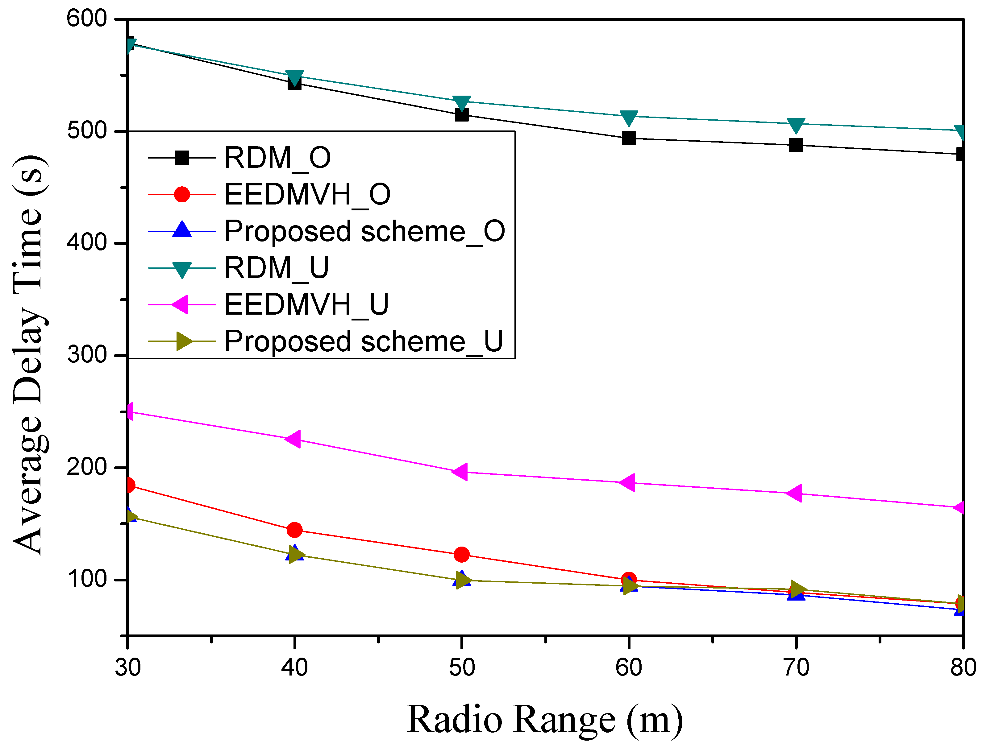
  • Reducing the average delay time for data transmission: Since previous hole-modeling research performs data transmission after it finishes the hole-modeling process, it cannot transmit the packet until after the hole-modeling process, and this causes a delay to packet transmission. The proposed scheme can reduce average delay time compared to existing studies because it does not perform the hole-modeling process and detours the hole area using face routing. In addition, as mentioned above, the proposed scheme does not use face routing continuously and mainly uses greedy forwarding after it detours the hole area using face routing. Therefore, since greedy forwarding uses fewer nodes compared to face routing, the proposed scheme can reduce the average delay time for data transmission, compared to existing studies.
The remainder of this paper is organized as follows. Section 2 describes the related works on the disjoint feature of multipath, regarding their research details and limitations. Section 3 explains our proposed scheme to solve the limitations of previous research surrounding the disjoint characteristic of multipath. Section 4 shows the simulation results of the proposed scheme compared to a hole-modeling study and a face routing study. Section 5 summarizes and concludes this paper.

2. Related Work

This section introduces related studies for bypassing the hole area in multipath studies. In the hole area, it is impossible to communicate between each sensor [8,9,10,12,13,14,15,16,17,28]. A hole area can be generated because of sensor deployment in WSNs. In other words, since it is impossible to directly arrange millions of sensor devices one by one in large-scale networks, WSN research tries to distribute sensors using transportation similar to an airplane [1,2,3,4]. As a result, some areas have a lot of sensors, and some areas have few sensors. In areas with few sensor nodes, a hole area may occur.

2.1. Hole-Detouring Single-Path Research

Geographic routing is a well-known routing in WSNs in terms of energy efficiency [22,23,24,25,26,27]. When a sensor transmits a data packet using geographic routing, this routing does not use the connection information of the whole network, but uses local information that communicates with each neighbor within its radio range. Using local information within a one-hop range, geographic routing can maintain energy efficiency among sensors and, therefore, it has received attention from many WSN researchers. Geographic routing transmits data packets to a destination node using two modes—one is greedy mode, also known as greedy forwarding, and the other is recovery mode, also called perimeter routing. Greedy forwarding, which is the first mode in geographic routing, is a routing scheme that transmits data packets to a neighbor node close to a destination node within a one-hop range. Since all nodes know the location of a destination due to the characteristics of geographic routing, when a node receives the data packets, it generates a virtual line from a destination node to itself to transmit the data packets to a destination. This node makes the intersect area within a circle based on a virtual line and a circle based on its radio range. After that, this node selects a neighbor node closest to a destination node in this intersect area and transmits the data packets to the searched candidate node.
However, if there is no neighbor node in this intersection area between a circle based on a virtual line and a circle based on its radio range, greedy forwarding cannot transmit the data packets to a destination node, as shown in Figure 2 left. This situation creates a problem caused by random node deployment, which is a WSN characteristic. Due to the nature of WSNs, each node deploys randomly, so there may be some situations during which some area is denser or sparser regarding node deployment. A dense area of node deployment has many candidate nodes that can receive packets, but a sparse area does not have a candidate node to receive the packets. Therefore, a candidate node area may face an impossible communication situation. This area in which an impossible communication situation occurs is called a hole area. For this reason, when a node faces a hole area during data transmission, it cannot transmit data packets to a destination node using greedy forwarding. In other words, although there are many neighbor nodes within its one-hop area, when there is no candidate node in an intersection area between a circle based on a virtual line and a circle based on its radio range, a node cannot transmit data packet to a destination using greedy forwarding.
To solve this problem, geographic routing changes to a perimeter routing mode, which is a recovery mode that transmits a data packet to a destination node as shown in Figure 2, right. Face routing is one of the famous perimeter routings and, unlike greedy forwarding, it generates particular graphs and exploits these graphs to find candidate nodes for data transmission. The basic idea of face routing is to find an exit route by moving in one direction continuously in a maze. In other words, after face routing generates its particular graph based on its neighbor nodes, it transmits the data packets to candidate nodes by searching in one direction, as mentioned in the maze-exit method. Using this scheme, the destination node can receive data packets in a hole situation. In face routing, this particular graph is called a planar graph. When a node generates a planar graph, this graph selects shorter links to avoid the routing loop state that repeatedly communicates with the same nodes as in previous research [22,23,24,25,26,27]. Since this graph is generated based on a one-hop range for each node, the node does not need to collect information for entire network, and, therefore, it greatly reduces the overheads for graph generation and maintenance.
However, when geographic routing compares greedy forwarding with face routing, face routing increases delay for packet transmission. Face routing generates a planar graph locally within a one-hop range and transmits data packets to the searched candidate nodes by searching one direction based on a local planar graph. Since face routing selects candidate nodes in one searched direction, the generated planar graph may be far from a destination node, and it may cause a delay problem for packet transmission when a node uses face routing based on this local planar graph. For this reason, in geographic routing, after a node uses face routing, it checks whether it is possible to change from face routing to greedy forwarding each time.
To prevent this limitation, many WSN researchers have paid attention to a hole-modeling scheme that is a handling scheme for a hole area. This makes a modeling of a hole area and then detours and transmits data packets by maintaining the greedy forwarding scheme even as the packets arrive at the hole-modeling area. In reference [29,30,31], when a node faces a hole area at first, it detects a hole area by transmitting a hole boundary detection (HBD) message to its neighbor nodes nearby a hole area. The purpose of the HBD message is to detect all neighbor nodes located around a hole area. The node that finds a hole area selects the first node that searches in one direction, and transmits an HBD message to a searched candidate node. When a node receives an HBD message from its neighbor nodes, it transmits this HBD message to a detected candidate node in the searched direction. This process continues until the HBD message arrives at the node that first discovered a hole area. When the first node that detects a hole area receives an HBD message from its neighbors, it can identify information that locates the nodes around a hole area, and this node can generate a hole model. After that, this node transmits information on hole modeling to nodes related to the hole model, so that these related nodes can receive and maintain a hole model. After that, when other source nodes transmit data packets and these packets reach nodes that maintain the hole model, they transmit these packets to other areas that are not located in the hole area. Therefore, when this hole-modeling scheme is compared with previous recovery modes such as face routing, it can solve the routing problem by avoiding a hole area and it can reduce delay by maintaining greedy forwarding.

2.2. Hole-Detouring Multipath Research

The necessity for multipath in WSN exists because of the characteristics of deployed WSN sensors. Since WSNs exploit hundreds of thousands of sensors, their sensors have a characteristic that reduces resources and makes the size smaller. For this reason, in WSNs, when a node tries to do data transmission through a single path, its reliability is vulnerable to some conditions such as noise, due to the low quality of the sensors. To improve transmission reliability in various environments, WSNs use a multipath that consists of several single paths. By transmitting data packets to a destination through multipath, reliability can be improved for data transmission compared with single paths and it can maintain load-balancing for data traffic through multipath. In multipath research, the disjoint feature is an important issue to address. The disjoint feature means that it does not use the same single paths or the same nodes in generated multipaths. When each multipath does not keep the disjoint feature and continues to use the same paths or same nodes, this depletes the energy of sensors used in duplicated paths. To prevent this problem, the multipath should maintain the disjoint characteristic to extend the lifetime of each sensor.
In particular, it is hard for multipath to maintain this disjoint feature in a hole area. As shown in Figure 3, when a source node S generates a multipath using geographic routing around a hole area, it overlaps its paths, and this results in a break of disjoint feature. For example, in Figure 3, a path A, B, and C of node S tries to generate each path with the disjoint feature to a destination node D using geographic routing at first. However, since each path in the hole area proceeds with face routing as a recovery mode of the geographic routing, a path-overlapping problem in the hole area occurs. This is because face routing is a recovery routing method based on generated local planar graphs, and each path transmits data packets based on a local planar graph without discriminating against nodes used in other paths near a hole area.
To solve the problem where the disjoint characteristic is broken in the hole area when generating the multipath, RDM [16,17] proposes a scheme to avoid the hole area using hole modeling. By using virtual hole modeling, RDM can maintain greedy forwarding without switching to face routing around a hole area. In this scheme, during multipath generation, when a node encounters a hole area, it generates its path using face routing and transmits data packets to a destination with node information that detours around the hole area. Thereafter, the destination node receives the data packets by avoiding the hole area through face routing. The destination node can identify a hole area through the received packets, and makes a virtual grid based on the received packet information, and then it constructs a hole model. After that, to inform a source node about this hole-modeling information, a destination node transmits modeling information to a source node through a path received by the data packets from a source node. When a source node receives this information from a destination node, it can keep the disjoint feature of multipath by selecting candidate nodes in the next multipath generation, avoiding the hole-modeling area.
However, RDM causes an overhead on sensor nodes that have limited resources because it needs to check the hole area continuously. Since the hole area may change due to an impossible situation of sensor communication and the death of sensors, this scheme should check every time. The continuous checking of a hole area causes additional energy consumption to sensor nodes that use hole-modeling, therefore increasing node energy consumption. In addition, whenever the shape of the hole area changes, RDM needs to collect hole information again, and then it updates the new hole shape to sensor nodes around the hole area. Therefore, this scheme causes a lot of overheads to sensor nodes around the hole area and accelerates their energy consumption. If this situation is maintained continuously, the nodes around the hole area run out of their limited energy, they cannot maintain multipath due to their death around hole area, and then the hole area becomes larger.
To handle this limitation, EEDMVH proposes a novel scheme that maintains the disjoint feature of multipath studies using face routing around the hole area, when it generates new multipaths [28]. Unlike greedy forwarding, face routing makes a local special graph based on the neighbor nodes, and it can detour the hole area based on this graph. However, when previous face routing studies create several new multipaths, they overlap their multipaths because face routing research should follow local graphs without considering multipath characteristics. EEDMVH does not use nodes that generate the path when it creates the new path. When EEDMVH switches to face routing around the hole area, it performs a marking process on the used nodes whenever it finds some candidate nodes for face routing. When a node that performs a marking operation exchanges information with its neighbor nodes, it notifies it that this node is a used node by transmitting marking information to its neighbors.
Although EEDMVH detours the hole area without hole modeling, it causes a large amount of data transmission because it bypasses face routing around a hole area, as shown in Figure 1. To avoid the routing loop situation where packets do not leave same area and stay in the same area repeatedly, when a node uses face routing and makes the local special graph, it generates a local special graph based on nodes that are the closest neighbor nodes from its node. Since face routing tries to transmit the packets based on this local graph, packet transmission distance is usually the shortest distance, and this situation results in increased data transmission whenever each node uses face routing. Although a node using face routing has the farther neighbor nodes, which can reduce the amount of data transmission, due to the characteristic of face routing that selects the shortest neighbor nodes to avoid a routing loop situation, it chooses the shortest neighbor nodes in its radio range. In addition, the weirder and the bigger the hole shape, the more frequently short transmissions occur. As a result, this research causes unnecessary energy consumption and increases delay due to short packet transmission distance.
To solve this limitation, this paper uses two approaches that reduce energy consumption of the node and delay time of data transmission near a hole area. This paper introduces an entire approach about data transmission from a source node to a destination node during multipath generation and a local approach that does not use duplicate nodes near a hole area. In the next section, we describe these two approaches in detail.

3. Proposed Hole-Avoiding Multipath Scheme

To maintain the disjoint feature of multipath research, the proposed scheme suggests novel face routing consisting of two approaches; the first is global joint avoidance, and the second is local joint avoidance.

3.1. Global Joint Avoidance

Global joint avoidance is an approach that maintains the disjoint features between each multipath. With this approach, the proposed scheme deals with how to discover a hole area and how to generate multipaths near a hole area.

3.1.1. How to Generate New Multipaths near a Hole Area

In this approach, the proposed scheme generates a multipath based on a virtual S–D line at first [22,28]. The virtual S–D line is a virtual line from a source node to a destination node, and the proposed scheme uses this virtual line when it exploits the geographic routing scheme. When the proposed scheme does not generate multipaths based on an S–D line, this may happen as an isolated situation between generated multipaths. For example, we assume that there was a hole area between a source node and a destination node, and we assume that two generated multipaths already detoured the up and down parts of this hole area. After that, when the proposed scheme generates a new multipath between two generated multipaths, it cannot transmit a data packet to a destination node, since two generated multipaths block a new multipath in the up and downside and a hole area exists in the middle part.
To solve this problem, the proposed scheme generates a new multipath centered on a virtual line, called the S–D line, from a source node to a destination node. Therefore, whenever the proposed scheme generates a new multipath, it should select a candidate node close to the virtual S–D line to avoid an isolated situation, as mentioned above. Each node receiving a packet can calculate a virtual line because it knows the location information of the source and destination. If the proposed scheme generates a new path by selecting the closest candidate node near a virtual S–D line, the next new path can avoid an isolated case such as path C between two multipaths, as shown in Figure 4.
In addition, the proposed scheme should consider the searching direction of the candidate nodes during new multipath generation. For example, as shown in Figure 5, a source node generates a path A and tries to generate a new second path. During the second multipath generation, a node encounters the hole area again and searches for candidate nodes with the same searching direction. However, since the generated path A blocks the upper side of the hole area in the second multipath generation, it is better to change node selection direction from a counterclockwise direction to a clockwise. If the hole area is bypassed by keeping the original searching direction of face routing, it is inefficiently bypassed as shown in path C in Figure 5 in order not to use duplicate nodes. To avoid such inefficient detouring, the proposed scheme maintains efficient face routing by changing the search direction of face routing, as shown in path C’. As shown in Figure 5, when comparing path C’ with path C, path C’ has a shorter path length than path C. This means that the proposed scheme is more efficient because it can reduce the path length, such as path C’.

3.1.2. Enhanced Marking Process Detouring a Hole Area

The marking process means a memorized work that identifies used nodes in order not to repeatedly use the same nodes in generated multipaths. This operation notifies used node information during multipath generation to the neighbor nodes. When the proposed scheme encounters a hole area, it marks first the nodes that detoured a hole area in the multipath. In the marking process, these nodes are the nodes used to generate the multipath around a hole area. When the proposed scheme generates a new path around a hole area again, it uses these nodes again. By marking the nodes used in the multipath around a hole area, this process can avoid using the same nodes in multipath generation and can maintain the disjoint feature of multipath.
However, this process cannot cover the hole area by marking only nodes used in the multipath around a hole area. As a hole area usually does not consist of simple shapes such as a square, it may have an unpredictable and obscure shape in network. Therefore, since this process does not completely mark out a hole area, it may repeat again when it generates a new multipath around a hole area. This situation is inefficient in terms of node energy, whenever it occurs. To prevent such a situation, such as inefficient node energy consumption, the proposed scheme selects the nodes to be marked in the next step.
To prevent the repeated detour case in the hole area, the proposed scheme marks not only nodes used in other multipaths but also some partial area around the hole area in order not to generate inefficient multipaths with face routing. When the proposed scheme generates new multipaths around a hole area at first, it can find a last node that detours around a hole area to announce the information of this node to the source node. After the proposed scheme finds this last node, this last node can calculate some area to be marked based on itself before it announces the information to the source node. The proposed scheme uses a line equation between a source node and a destination node, and it can calculate a perpendicular line length based on this node position. This is possible because the information of the source and destination node already exists in the packet, and all used nodes already know the destination position in the geographic routing scheme. Therefore, based on the source node ( x 1 , y 1 ) and destination node ( x 2 , y 2 ), the proposed scheme can make a line Equation (1) as follows:
y y 1 = y 2 y 1 x 2 x 1 ( x x 1 )
After calculating this line Equation (1), the proposed scheme generates a perpendicular line centered on a last node that detours around a hole area. Since this node is the first node to leave a hole area, it means that this node is a boundary point outside a hole area. If the proposed scheme generates a detour area for a hole area using a perpendicular line based on this last node, it can maintain a disjoint multipath feature and avoid the aforementioned repetition situation of inefficient energy consumption. For this reason, the proposed scheme can identify an area to be marked based on a perpendicular line from this node. The proposed scheme exploits a Formula (2) to find a length D that is the distance of a perpendicular line between a coordinate ( x 1 , y 1 ) and a straight-line equation a x + b y + c = 0 as follows:
D = | a x 1 + b y 1 + c | a 2 + b 2
After that, the proposed scheme makes a marking area to detour a hole area based on this information. Using the marking operation, the proposed scheme can detour the hole area without the hole-modeling operation. In the hole area, since the proposed scheme consists of boundary nodes near hole area using face routing, it does not need to additionally identify the existing boundary nodes near the hole area, unlike the existing studies. This detail-marking operation introduces an approach of local joint avoidance.

3.2. Local Joint Avoidance

Local joint avoidance keeps a local disjoint feature between generated multipaths. The proposed scheme uses the marking process and calculates the hole area to maintain a local disjoint feature of multipath in this view.

3.2.1. Marking Process

As mentioned above, the marking process does not repeatedly use the same nodes by announcing the used nodes to their neighbors during multipath generation. The proposed scheme uses the marking process that selects the used candidate nodes of face routing. Face routing exploits local unique graphs, called the planar graph, which consists of adjacent neighbors in a one-hop range of each node [22,23,24,25,26,27]. Using this local graph, face routing can guarantee the connectivity of data transmission [25]. Due to this guarantee of face routing, the proposed scheme uses face routing, and generates each planar graph when all nodes exchange their information with each other at the initial setting time.
After each node generates its local planar graph, the proposed scheme exploits this graph with face routing when it generates a new multipath. After that, whenever the proposed scheme selects the candidate nodes for face routing, it generates a new path based on these selected candidate nodes. For example, node A is a selected node, and it tries to find a candidate node for face routing in new multipath generation, as shown in Figure 6. Node A can find its candidate node B, node C, and node D during face routing. When face routing searches the candidate node with a counterclockwise searching direction, node A can select neighbor node C. After node A selects neighbor node C, the proposed scheme repeats this process based on node C. This face routing repeats until the proposed scheme can use greedy forwarding. After that, to maintain the local joint avoidance for disjoint multipath, node A prepares a beacon message that neighbor node C is already using, and transmits this message to node B and node D as shown in Figure 6. When node B and node D receive this message from node A, they remember neighbor node C and do not select this node C when they generate a new path, as in the case of node A. Therefore, by transmitting information about used nodes to unused neighbor nodes with face routing, these unused neighbor nodes can avoid selecting the same used candidate nodes for face routing when they generate a new multipath next time.
Therefore, the proposed scheme uses this process called marking to improve energy efficiency and reduce the delay to packet transmission. As mentioned above, this marking process notifies other neighbor nodes to announce the information of used nodes in multipath, and it prevents use of these nodes when a source node generates a new multipath later. Therefore, the proposed scheme can avoid the redundancy of node selection for multipath generation. By taking advantage of this point, the proposed scheme can maintain the disjoint characteristic of multipath without using an additional method such as hole modeling.

3.2.2. Marking Process in a Hole Area

The proposed scheme performs this step when it calculates the length of a perpendicular line using Equation (2) in an approach of global joint avoidance in Section 3.1.2. Based on this length of perpendicular line D, the proposed scheme can generate an isosceles triangle to perform a marking process, as shown in Figure 7. As shown in Figure 7, the reason that it generates an isosceles triangular region around the perpendicular length D is to easily detour the difficult hole area as in the horseshoe-shaped hole region. If the proposed scheme makes the detour hole area small or incorrect, it needs to regenerate the detour area again. To reduce this mistake, the proposed scheme generates an isosceles triangle detour area based on the length of the perpendicular line D to bypass the hole area. The proposed scheme can find the area of an isosceles triangle based on the coordinates of the last node and a perpendicular line D in the hole area. When there are neighbor nodes included in the calculated isosceles triangle, the proposed scheme performs a marking process on them to maintain a disjoint feature of the multipath. After this, the node performs the marking process with related neighbor nodes, and transmits information of an isosceles triangle area to a node of the previous order belonging to the multipath to announce a marking area. In addition, since the proposed scheme may change criteria about a marking process depending on the situation that has deployed the nodes, it also transmits information about a perpendicular line foot to a node of previous sequences belonging to a multipath.
After that, the proposed scheme can identify the coordinates of a perpendicular line foot using an orthogonal formula using two straight lines. Using straight-line Equation (1) between the source and destination node as mentioned above, the proposed scheme can identify the first straight line to be used in orthogonal formula between two straight lines. After that, to find another straight line, using a slope formula, the proposed scheme can identify the second straight line to be used in orthogonal Formula (3) between two straight lines. According to the orthogonal formula of two straight lines, the proposed scheme can use the point that this formula reaches −1 when each slope multiplies. Since a perpendicular line is one of the orthogonal straight lines, the proposed scheme can find a foot of the perpendicular line based on orthogonal Formula (3). When this Formula (3) assumes that the current node has a coordinate of ( x 1 , y 1 ) and a foot of perpendicular line has a coordinate of ( x 2 , y 2 ), the proposed scheme can calculate slope Formula (3) as follows;
a y 2 y 1 x 2 x 1 = 1 , x 1 + a y 1 ( x 2 + a y 2 ) = 0
The proposed scheme can use this Equation (3) to find a perpendicular line foot. When the proposed scheme defines a perpendicular line foot as an unknown quantity and substitutes given constants for other variables, it can obtain two straight-line equations. For this reason, using two straight-line equations, the proposed scheme can find the coordinates of the foot of the perpendicular line. For example, the proposed scheme assumes that the straight line is a x + b y + c = 0 , the source node has (1,2) coordinate, and the destination node has (10,20) coordinate. Using two coordinates that are the source node and the destination node, the proposed scheme can obtain one straight-line equation, such as 2 x y = 0 . Since the slope is 2 in the first straight-line equation, it means that the other slope is 1 2 in orthogonal Formula (3). In addition, the proposed scheme assumes that a node that finishes face routing has (5,5) coordinates. Since the other slope is 1 2 , the proposed scheme can obtain one straight-line equation, such as x + 2 y 15 = 0 by calculating 1 2 = 5 y 1 5 x 1 . By solving simultaneous equations with two straight-line equations, the proposed scheme can find that x is 3 and y is 6. Likewise, after the proposed scheme finds a coordinate of a perpendicular line foot by using the orthogonal formula, it transmits this information to a previous node belonging to the multipath. In addition, the current node also includes a horizontal coordinate corresponding to the vertex of the triangle when it transmits the packet. Since this is a necessary part of determining the criteria of the triangle to be marked, the proposed scheme uses the coordinate and the length of the foot of the perpendicular line and then it can identify a coordinate of horizontal vertex. After the proposed scheme discovers the length of the perpendicular line, it exploits the Euclidean distance formula to identify the part of the horizontal vertex coordinate corresponding to the isosceles triangle area to be marked. Euclidean distance Formula (4) and its horizontal vertex coordinates for a x + b y + c = 0 about ( x 1 , y 1 ) are as follows.
D = ( x 2 x 1 ) 2 + ( y 2 y 1 ) 2 , x 1 = b y 1 + c a , y 1 = a x 1 + c b
Using the aforementioned coordinates and Euclidean distance Formula (4), the proposed scheme can identify two calculated coordinates. Between two coordinates, if the proposed scheme compares each distance from a source node and selects the coordinate closest to the source node, it can find a horizontal vertex coordinate used in an isosceles triangle area to be marked. For example, through coordinate (1,2) of the source node and coordinate (10,20) of the destination node, the proposed scheme can obtain a straight-line equation 2 x y = 0 . After that, in this example, when a node that finishes face routing has a coordinate (5,5), the proposed scheme can find that the length of the perpendicular line is 5 and that the coordinate of the foot of the perpendicular line is (3,6). Based on this example, using the Euclidean distance formula, when the proposed scheme calculates a horizontal vertex coordinate, it can obtain two coordinates—one is (2,4) and the other is (4,8). Between two coordinates, when each calculated coordinate compares the distance from a coordinate (1,2) of the source node, a coordinate (2,4) is closest to the source node and, therefore, the corresponding horizontal vertex coordinate is (2,4).
To sum up, in the proposed scheme, a node, which is out of the hole area and is the end point of face routing, transmits a packet that includes three pieces of information to the previous node involved in the multipath. In this packet, the three pieces of information are the length of the perpendicular line, the coordinate of the foot of the perpendicular line, and the horizontal vertex coordinate of an isosceles triangle area to be marked.
After that, when a node receives this packet, it identifies three pieces of information—the length of the perpendicular line, the coordinate of the foot of the perpendicular line, and a horizontal vertex coordinate of the isosceles triangle area to be marked. This node compares these three pieces of information one by one between the three calculated values and three values in the packet. This is because the hole area has an irregular shape, and therefore it is necessary to check each value to see whether each node is included in the isosceles triangle area to be marked. When this node is compared to a calculated length of a perpendicular line with a length of perpendicular line in the packet, if the calculated length is shorter than the length in the packet, the calculated triangle area based on the current node is included in the triangle area in a packet according to the law of triangular congruence. After that, the proposed scheme calculates distance from a source node to a coordinate of the perpendicular line foot to determine that the current node is included in a marking area. Then, it compares each distance from a source node to two perpendicular line coordinates. If the distance of a calculated coordinate is closer than a coordinate included in a packet, it means that the current node does not leave the area of an isosceles triangle to be marked in the packet. Finally, the current node calculates a horizontal vertex coordinate of an isosceles triangle area, and then it calculates the distance between this coordinate and the source node. After that, it compares this value with a distance based on a horizontal vertex coordinate included in the packet. If a calculated distance of the current node is longer than a distance included in packet, it means that the current node is included in an isosceles triangle area to be marked in the packet.

3.2.3. Identification for Marking an Isosceles Triangle Area

After the proposed scheme calculates the length of the perpendicular line, a coordinate of the foot of the perpendicular line, and the horizontal vertex coordinate of the calculated isosceles triangle area, it checks to include the isosceles triangle area to be marked from information in the packet. In the first condition, it is included in the isosceles triangle area to be marked if the length of the perpendicular line in the current node is shorter than the length of the perpendicular line in the packet. In the second condition, it is included in the isosceles triangle area to be marked if the coordinate of the foot of the perpendicular line in the current node is closer to the source node than a coordinate of the foot of the perpendicular line in the packet. In the third condition, it is included in the isosceles triangle area to be marked if the calculated coordinate of the horizontal vertex in current node is further to the source node than the coordinate of horizontal vertex in packet. If the current node meets all three conditions, it generates an isosceles triangle area based on the information from the received packet, and then it calculates its neighbor nodes included in the isosceles triangle area to be marked. After that, this current node marks itself and all its neighbor nodes included in the isosceles triangle area within its one-hop range. In this marking process, a current node identifies an isosceles triangle area to be marked, and transmits a beacon message to its neighbors to mark its neighbor nodes included in the isosceles triangle area. For this reason, the proposed scheme can maintain the disjoint feature of multipath research, and can avoid marked nodes when it generates a new multipath. Therefore, using a marking process, the proposed scheme does not need to generate a multipath around a hole area unnecessarily. After that, the current node transmits the received packet to the previous node of the involved multipath, so that the proposed scheme continuously performs the marking process.
If the current node does not satisfy one of the three conditions, it determines that it is out of the isosceles triangle area to be marked and it resets based on the current node. As mentioned above, since the hole area has an irregular shape, the current node may fall outside of the three conditions. When the proposed scheme does not satisfy one condition out of three conditions, it determines that the current node may include a hole area that is not covered by the node set as the standard in the packet, and then it resets based on the condition value calculated at the current node. In the first condition in the marking process, if the currently calculated length of the perpendicular line is longer than the reference length of the perpendicular line in the packet, this means that the setting of the isosceles triangle area to be marked does not cover all the hole areas. For this reason, when the current node has a longer calculated length of perpendicular line than the reference length of perpendicular line in the packet, the proposed scheme resets based on the current node as a reference, and it can cover the hole area to be marked. In the second condition in the marking process, the calculated coordinate of the foot of the perpendicular line is a further distance from the source node than a reference coordinate of the foot of the perpendicular line in the packet, which means that the reference node in the packet does not widely cover the hole area to be marked. Accordingly, in the second condition, when the foot coordinates of the waterline are further from the distance from the source node than the reference node, the current node is reset to the reference node to cover the hole area to be marked. In the third condition in the marking process, if the calculated coordinate of the horizontal vertex is a closer distance from the source node than a reference coordinate of the horizontal vertex in the packet, this is a case outside the range of the reference node of the hole area to be marked. In this case, the proposed scheme resets the information in a packet to the current node so that it can cover a hole area to be marked. To sum up with this information, the proposed scheme determines the reference node that creates an isosceles triangle to cover the hole area, check the three conditions mentioned above, and, if the current node satisfies all three conditions, it transmits the received packet to the previous node of the involved multipath. If any of the three conditions mentioned above is not satisfied, the current node is used as a reference node, and it transmits the changed information of the current node to the previous node of the involved multipath.
The proposed scheme finishes the marking process when it satisfies one of two conditions. The first stop condition is that the current node receives the packet and stops the marking process when the length of the perpendicular line becomes zero. This means that the current node is located in a horizontal coordinate, which is the vertex of the isosceles triangle area to be marked, and it means that there are no neighbor nodes to be marked except itself. This condition is rarely possible, because of the mathematical calculation, but the proposed scheme should prepare for this condition since it may happen due to WSN deployment that arranges nodes arbitrarily. In this case, since the proposed scheme only marks the current node, it is no longer necessary to perform the marking process, and, therefore, it stops the marking process at this node. In the second condition, the proposed scheme stops the marking process when the current node is closer to the source node than to the vertex of the isosceles triangle area to be marked. This situation means that the current node goes further over the horizontal vertex of the isosceles triangle area to be marked and, in this case, the current node is closer than the horizontal vertex, when each point is compared with the distance from source node. In addition, in this case, since the current node has passed the isosceles triangle area to be marked, there are no more neighbor nodes to be marked. As mentioned above, since the horizontal vertex of the isosceles triangle area is calculated using orthogonal equation, the proposed scheme has low probability of finding a node that has calculated the exact last position, and the current node may be closer than the calculated node when both nodes compare the distance from the source node. As with the case of the first condition in the proposed scheme, since there are no more neighbor nodes to be marked, the proposed scheme stops the marking process at this current node. After that, the current node that stopped the marking process transmits this information to the source node to announce the information is finished, and to be ready to generate a new multipath around the hole area. Then, the source node can prepare to generate a new disjointed multipath. Later, when the source node generates a new multipath, since marked nodes are not used, the proposed scheme can create a not unnecessary multipath around the hole area and it can maintain the disjoint feature of multipath.

4. Performance Evaluation

This section shows the simulation results by comparing each multipath study. There are three compared multipath studies—one is a hole-modeling scheme that makes a hole-detour area based on searched hole boundary nodes, another is a face routing scheme that performs a marking process to avoid the duplicated nodes in path generation, and the third is the proposed scheme. This section shows the simulation environment at first, and then it explains the simulation results compared with selected multipath studies.

4.1. Simulation Environment

This section shows the simulation environment in detail for the performance evaluation. This paper exploits the Network Simulator (NS-3) simulator [32] to compare with existing disjoint multipath studies. Table 1 shows simulation parameters to use in this simulation. In the initial time of the network, each node exchanges location information using IEEE 802.15.4 physical and MAC layers.
The nodes were placed in a square area of 1000 × 1000 m 2 area and uniformly arranged with 100 nodes to obtain good experimental results. The end-to-end distance means the entire packet transmission path from a source node to a destination node and is initially set at 100 m. This distance will change from 50 m to 100 m when the simulation exploits this condition. As this distance decreases, the communication around the hole area becomes shorter. Therefore, this simulation can check the simulation effects of each hole-detour scheme. The one-hop range of a node is initially set to 50 m and this radio range will change from 30 m to 80 m when the simulation uses this condition. Accordingly, as this one-hop range of a node increases, the number of candidate nodes for greedy forwarding also increases, and it can check the influence to reduce the amount of entire data transmission.
In this simulation, there are three existing multipath studies. The first simulation target is RDM [16,17], in which a hole-modeling study makes the hole-detour area by searching the nodes near the hole area. Additionally, since this study is one of the hole-modeling methods in the disjoint multipath research, it is selected as a comparison target in this simulation. The second simulation target is EEDMVH [28], which keeps the disjoint characteristic of the multipath using the face routing. Since this scheme is also one of the energy-efficient hole-detour schemes in the disjoint multipath research, it is selected as a comparison target in this simulation. The last simulation target is the proposed scheme that solves the aforementioned previous limitation of multipath research. Therefore, the performance evaluation shows the results compared to three simulation comparison targets.
There are three used conditions in this simulation: the first condition is the size of the hole area, the second condition is the end-to-end distance from a source node to a destination node, and the third condition is the radio range of a node. The first simulation condition is the size of the hole area in the network. In this first condition, this simulation selects hole center coordinates and configures the hole circle based on the hole center coordinates. Based on this information, this simulation changes a radius of this hole circle. As the size of the hole area increases, the amount of hole-detour transmission increases. Since this condition increases the amount of hole-detour transmission, simulation comparison targets will show their results according to the size of the hole area. The second simulation condition is the end-to-end distance between a source node and a destination node. This end-to-end distance is the Euclidean distance from a source node to a destination node. As end-to-end distance decreases, the data transmission around a hole area becomes shorter. Thus, since this distance can reduce the amount of data transmission, each simulation comparison target will show its results according to end-to-end distance. The third simulation condition is the radio range of a node. As this radio range of a node increases, greedy forwarding can find a greater number of candidate nodes. Therefore, since greedy forwarding can reduce the amount of data transmission due to radio range size, each simulation comparison target will show its results according to the radio range of a node.
There are two simulation results in this performance evaluation—the first calculated result is the average energy consumption of a node, and the second is the average delay time of a node. In the first result, the average energy consumption of a node is the average value of energy consumption per each used node during data transmission. During the simulation, all used nodes measure energy consumption in data transmission. In communication parts, the physical layer or MAC layer may be related to energy consumption of a node. However, since this simulation only targets the routing part of a network layer, it does not mention energy consumption in a physical layer and MAC layer. Using this result, the simulation can identify which schemes are more efficient and inefficient in terms of average energy consumption. In the second result, the average delay time of a node is the average delay value per used node during the data transmission. Using this result, the simulation can figure out which scheme has less delay time in data transmission. To obtain average simulation results, the simulation is repeated 40 times per result graph by changing the simulation conditions.

4.2. Simulation Results

Figure 8 shows average energy consumption according to hole size. This simulation tests two hole models—one is the circle hole model, and the other is the horseshoe model. The result for the circle model has _O on the backside of each study, and the result for the horseshoe model has _U on the backside of each study. As shown in Figure 8, among the simulation comparison targets, RDM has the highest average energy consumption for both the hole circle model and hole horseshoe model. Unlike other research, this research wastes a lot of energy because of the hole-modeling process. When RDM encounters a hole area, it searches the hole area and makes the hole modeling first and then it makes a new path by avoiding the generated hole modeling area. In addition, when this study searches all the nodes near the hole area, its nodes need to keep this hole-modeling information to announce the hole boundary area continuously, and this result requires more communication between nodes to be processed. Therefore, this research shows the highest average energy consumption, as shown in Figure 8 because it increases the amount of communication compared to the other two studies. Additionally, as the hole size increases, the number of nodes included in the hole-modeling area increases, which further increases the average energy consumption.
In addition, as the number of parts to bypass the increased hole area increases, the amount of communication increases as well, resulting in an increase in average energy consumption. Among the simulation comparison targets, EEDMVH has lower average energy consumption than RDM. EEDMVH can detour the hole area without hole modeling because it uses face routing whenever it encounters a hole area. Therefore, this research can reduce the amount of additional communication compared with RDM. EEDMVH can distinguish the used node in multipath by marking the used nodes in the generated path, and thus it can generate a new multipath by maintaining the disjoint characteristic of the multipath not to use the same nodes. Since this research detours only the hole area using face routing, the number of hole-bypass nodes gradually increases as the size of the hole area increases. The proposed scheme has the lowest average energy consumption compared to other simulation targets because it does not select the nodes near the hole area after it explores the hole area. The proposed scheme identifies areas that should not be selected near the hole area while detouring the hole area such as the simulation target used in face routing. Unlike RDM, which uses face routing whenever meeting a hole area, the proposed scheme selects candidate nodes by greedy forwarding based on this information to avoid the hole area. Since the simulation shows all results of the comparison simulation targets in Figure 8, it seems that there is no difference between the two models of the proposed scheme. In addition, since the proposed scheme tries to mainly use greedy forwarding to reduce the number of used nodes in data transmission except for hole-detour process, it shows similar results between two models. For this reason, there is little difference between the two models for the proposed scheme. The proposed scheme can reduce the amount of communication compared with the two simulation targets. In addition, it has 5–20% lower average energy consumption than the simulation target using face routing.
Figure 9 shows the average energy consumption according to end-to-end distance from the source node to the destination node. As mentioned above, we mark with _O as the simulation results for the hole circle and mark with _U as the simulation result for the hole horseshoe model. Among the three comparison targets, RDM has the highest average energy consumption in both hole models due to hole modeling, as previously mentioned. The study using hole modeling should check the nodes near the hole boundary area periodically because the hole area may be larger under some conditions, such as dead node, noise, etc.
By maintaining the hole-modeling area, RDM can detour the hole area safely, but that increases the additional average energy consumption due to hole modeling. As shown in Figure 9, as the distance shortens, the number of packet transmissions from the source node to the destination node decreases, and the energy consumption gradually decreases. On the other hand, EEDMVH can reduce the average energy consumption significantly when it compares with the research using hole modeling because it can detour the hole area without hole modeling. Unlike RDM, when this research faces the hole area, it can detour the hole area using face routing. Since there is no node required to model the hole area in this research, it can reduce the average energy consumption compared the previous simulation target. In addition, RDM can maintain the disjoint characteristic of multipath because it does not reuse marked nodes that it already uses as paths. As shown in Figure 9, even if the end-to-end distance is shortened, there is little effect on the amount of communication to detour the hole area. The proposed scheme has the lowest average energy consumption among the simulation targets because it identifies the hole area using face routing and then it avoids the identified hole area using greedy forwarding. This research is similar to the research using hole modeling, but it does not use the same hole-modeling process. Research using hole-modeling models larger than the shape of the hole area in order not to select the neighbor nodes near the hole area. However, when the proposed scheme encounters a hole area, it detours the hole area through face routing. After that, the proposed scheme identifies the detoured nodes near the hole area, and it generates a new path by avoiding the identified detour area. In addition, unlike EEDMVH, which uses face routing when it encounters a hole area, the proposed scheme uses greedy forwarding by avoiding the identified detour area when it generates a new multipath. Since the proposed scheme tries to mainly use greedy forwarding except for in the hole-detour process, there are similar results for the two hole models. Therefore, the proposed scheme can reduce the number of required nodes for data transmission around the hole area compared to the previous simulation target using face routing. As the distance decreases, the proposed scheme differs by about 20–30% from the simulation target using face routing.
Figure 10 shows the average energy consumption according to the radio range of each node. As with Figure 10, RDM, the research using hole modeling, shows the highest average energy consumption for the circular hole model and the horseshoe hole model among the three comparison targets, because of the high energy consumption required by the aforementioned hole modeling process. Due to the characteristics of greedy forwarding, as the radio range of each node increases, the number of candidate nodes that can transmit also increases. As a result, the overall amount of communication decreases, and then the average energy consumption decreases, as shown in Figure 10. As a result, due to the additional energy consumption maintained by hole modeling, this research has the highest average energy consumption among the three simulation targets. In Figure 10, EEDMVH, the research using face routing has lower average energy consumption than the research using hole modeling because it does not perform the hole-modeling process and detours the hole area with face routing. Since face routing generates a unique local graph and selects a neighbor node close to the destination in the search direction, it is difficult to reduce the amount of communication according to the radio range. When comparing this research to that using the hole-modeling process, it has a greater amount of data transmission. However, since the amount of additional energy consumption in hole modeling is larger than the amount of energy consumption in data transmission by face routing, as shown in Figure 10, the average energy consumption of EEDMVH is lower than RDM. The proposed scheme has the lowest average energy among the three comparison targets, because it generates a new path using mainly greedy forwarding to detour the hole area. As mentioned above, when the proposed scheme faces a hole area, it bypasses the hole area by face routing and delivers the packet to the destination node first. At the same time, it is possible to significantly reduce the amount of communication near the hole by identifying an area that could bypass the hole area and creating a new path, without selecting the bypass area and the node used by greedy routing. At the same time, the proposed scheme identifies a detour region calculated from the hole area, and then it can reduce the amount of communication near the detour region using greedy forwarding when it makes the next path. As the radio range increases, the number of candidate nodes that can be selected through greedy forwarding increases. Since the proposed scheme tries to mainly use greedy forwarding except for in the hole-detour process, there are similar results between the two hole models. Therefore, the proposed scheme can reduce the amount of communication, which results in the lowest average energy consumption compared to other simulation targets.
Figure 11 shows the average delay time according to hole size. As mentioned above, the simulation uses two hole models—one is the circle model, and the other is the horseshoe model. In Figure 11, we name _O as the circle model result of each simulation target, and _U as the horseshoe model result name. As shown in Figure 11, RDM has the highest average delay time among the three simulation targets. As mentioned earlier, unlike other simulation targets, since this research performs hole modeling to bypass the hole area, extra delay occurs. For this reason, RDM has the highest average delay time for both hole models when compared with the two simulation targets, as shown in Figure 11. As the hole size increases, extra delay time occurs according to the hole-search process. In addition, the communication delay time is increased in this study from the source node to the destination node due to the increase in hole size. As shown in Figure 11, EEDMVH has less average delay time than RDM. Since this research does not use the hole-modeling process, it can eliminate the extra delay time to create a hole model and detours the hole area using face routing whenever it encounters a hole area. In addition, EEDMVH performs a marking operation in order not to reuse the node used in the generated path, and it can maintain the disjoint characteristic of multipath by excluding the used node near the hole area when creating the next path. Likewise, in this research, the average delay time increases because as the hole size increases, EEDMVH increases the amount of data transmission for face routing. The proposed scheme has the shortest average delay time among the simulation comparison studies because this research identifies the hole area and then reduces the communication delay time using greedy forwarding. The proposed scheme identifies the hole-detour area while bypassing the hole area with face routing in a similar way to EEDMVH. After that, the proposed scheme creates a new path by selecting candidate nodes excluding the identified detour area and the used nodes, using greedy forwarding. For this reason, the proposed scheme can reduce the delay time for hole modeling and the communication delay time compared with the simulation target using face routing. As shown in Figure 11, the proposed scheme obtains an average delay time result that is 10–20% lower than EEDMVH.
Figure 12 shows the average delay time according to end-to-end distance from the source node to the destination node in the circular hole model and the horseshoe hole model. Among the simulation comparison targets, RDM has the highest average delay time, which is due to the hole-modeling process, as previously mentioned. In addition, this research has the highest delay time among simulation comparison research, due not only to the delay of the hole modeling, but also the delay in bypassing hole modeling. As the hole size increases, the delay time for hole modeling and the data transmission bypassing the area also increases. In another case, among the simulation comparison targets, EEDMVH has a lower average delay time than the hole-modeling research, as shown in Figure 12. This is because, as previously mentioned, this research detours the hole area using face routing without a hole-modeling process, which results in shorter average delay times compared to RDM. EEDMVH also has extra delay time due to face routing, but its time is shorter than the extra delay time for hole modeling. Therefore, as shown in Figure 12, its average delay time is shorter than the delay time of the hole-modeling research. Even if end-to-end distance is shortened, there is no significant effect on communication delay time bypassing the hole area. Therefore, as shown in Figure 12, a large change to EEDMVH could not be confirmed. Among the simulation comparison research, the proposed scheme has the lowest average delay time because it can bypass the hole area using greedy forwarding without hole-modeling maintenance. The proposed scheme does not perform the hole-modeling process, as mentioned above. It identifies the hole boundary nodes near the hole area while detouring it with face routing. After that, it selects other candidate nodes, excluding the identified hole area and the used nodes for generated paths when creating a new path. Unlike EEDMVH, which uses face routing every time in the hole area, the proposed scheme can reduce the average delay time in the identified detour area because it does not select the neighbor nodes in the detour area and selects the neighbor nodes to use greedy forwarding. As the distance decreases by percentage in Figure 12, the proposed scheme shows an average delay result time about 10–20% lower than EEDMVH.
Figure 13 shows the average delay time according to the radio range of a node in the circular model and the horseshoe model. As with other simulation result figures, RDM has the highest average delay time of the simulation targets due to extra delays in hole modeling and detouring transmission time. This research sharply decreases the average delay time according to the radio range through the farthest node selection of greedy forwarding. However, since RDM has additional delay time for the modeling process and the detour delay time according to the hole-modeling area, it has the highest average delay time compared to other simulation research, as shown in Figure 13. Furthermore, among the simulation comparison targets, EEDMVH shows lower average delay time than RDM because of the advantage of bypassing the hole area without hole modeling. As mentioned above, since this research uses face routing whenever it encounters a hole area, it can detour the hole area and can reduce the extra delay time caused by, e.g., the hole-modeling process. In Figure 13, as the radio radius increases, there is no advantage in EEDMVH. However, before or after EEDMVH leaves the hole area, it can use greedy forwarding to select the candidate node, and Figure 13 shows the effect of reducing the average delay time. The proposed scheme has the lowest average delay time among the three simulation targets, as shown in Figure 13. This is because it has the advantage of greedy forwarding node selection for each new path, and of not performing the hole-modeling process. Since the proposed scheme identifies a detour area that can bypass the hole area while detouring this area with face routing when it encounters a hole area, it has the advantage of maintaining greedy forwarding in the generation of new paths excluding this area. Compared with the simulation results, the proposed scheme shows an average delay time result that is about 7–30% lower than EEDMVH.

5. Conclusions

This paper proposes an energy-efficient and low-delay scheme that maintains the disjoint characteristic of multipath in the hole area. Although existing studies have their own scheme to detour the hole area, they have the limitation that they increase node energy consumption and packet transmission delay. To solve this limitation, the proposed scheme proposes a new scheme that can reduce energy consumption and packet transmission delay. First, the proposed scheme analyzes the hole-detour area during face routing when it encounters a hole area. After it analyzes the hole-detour area, it sends this information to a source node to identify the hole area. For this reason, the proposed scheme does not need to perform the existing large hole-modeling process and can save node energy compared to previous research, since this scheme identifies the required detour part. Second, since the proposed scheme mainly uses greedy forwarding near the hole area, it can reduce energy consumption and the delay in packet transmission compared to previous research. The proposed scheme applies a marking process that does not reuse the nodes used in the hole-detour area, and can generate a new path without an isolated problem near the hole area. In the performance evaluation, the proposed scheme shows significantly lower average energy consumption and delay than the other simulation comparison targets. In performance evaluation, the proposed scheme shows an average 30% improvement in terms of average energy consumption and delay time compared to other simulation comparison targets.

Author Contributions

H.C., S.O., Y.S. and E.L. contributed to conceptualization, organization, and performance analysis of this paper including writing and review. All authors have read and agreed to the published version of the manuscript.

Funding

This research was supported by Basic Science Research Program through the National Research Foundation of Korea (NRF) funded by the Ministry of Education (NRF-2021R1A6A3A01087875) and by the Ministry of Science and ICT (MSIT) (NRF-2020R1C1C1010692).

Institutional Review Board Statement

Not applicable.

Informed Consent Statement

Not applicable.

Conflicts of Interest

All authors declare no potential conflict of interests.

References

  1. Akyildiz, I.F.; Weilian, S.; Sankarasubramaniam, Y.; Cayirci, E. A survey on sensor networks. IEEE Commun. Mag. 2002, 40, 102–114. [Google Scholar] [CrossRef] [Green Version]
  2. Al-Karaki, J.N.; Kamal, A.E. Routing techniques in wireless sensor networks: A survey. IEEE Wirel. Commun. 2004, 11, 6–28. [Google Scholar] [CrossRef] [Green Version]
  3. Akkaya, K.; Younis, M. A survey on routing protocols for wireless sensor networks. Ad Hoc Netw. 2005, 3, 325–349. [Google Scholar] [CrossRef] [Green Version]
  4. Karl, H.; Willig, A. Protocols and Architectures for Wireless Sensor Networks; John Wiley & Sons: Hoboken, NJ, USA, 2007. [Google Scholar]
  5. Prathap, U.; Shenoy, P.D.; Venugopal, K.; Patnaik, L.M. Wireless sensor networks applications and routing protocols: Survey and research challenges. In Proceedings of the 2012 IEEE International Symposium on Cloud and Services Computing, Honolulu, HI, USA, 24–29 June 2012; pp. 49–56. [Google Scholar]
  6. Oh, S.; Cho, H.; Kim, S.H.; Lee, W.; Lee, E. Continuous object tracking protocol with selective wakeup based on practical boundary prediction in wireless sensor networks. Comput. Netw. 2019, 162, 106854. [Google Scholar] [CrossRef]
  7. Kim, C.; Kim, S.; Cho, H.; Kim, S.; Oh, S. An Energy Efficient Sink Location Service for Continuous Objects in Wireless Sensor Networks. Sensors 2020, 20, 7282. [Google Scholar] [CrossRef] [PubMed]
  8. Jones, E.P.; Karsten, M.; Ward, P.A. Multipath load balancing in multi-hop wireless networks. In Proceedings of the WiMob’2005, IEEE International Conference on Wireless and Mobile Computing, Networking and Communications, New York, NY, USA, 17–19 October 2005; Volume 2, pp. 158–166. [Google Scholar]
  9. Sha, K.; Gehlot, J.; Greve, R. Multipath routing techniques in wireless sensor networks: A survey. Wirel. Pers. Commun. 2013, 70, 807–829. [Google Scholar] [CrossRef]
  10. Masdari, M.; Tanabi, M. Multipath routing protocols in wireless sensor networks: A survey and analysis. Int. J. Future Gener. Commun. Netw. 2013, 6, 181–192. [Google Scholar] [CrossRef]
  11. Kim, C.; Cho, H.; Jung, K.; Yim, Y.; Yang, T.; Kim, S.H.; Kim, S. Agent-Based Multipath Management for Supporting Sink Mobility in Wireless Sensor Networks. Wirel. Commun. Mob. Comput. 2020, 2020. [Google Scholar] [CrossRef]
  12. Ganesan, D.; Govindan, R.; Shenker, S.; Estrin, D. Highly-resilient, energy-efficient multipath routing in wireless sensor networks. ACM SIGMOBILE Mob. Comput. Commun. Rev. 2001, 5, 11–25. [Google Scholar] [CrossRef]
  13. Lee, J.; Park, H.; Oh, S.; Yim, Y.; Kim, S.H. Radio-disjoint geographic multipath routing for reliable data transfer in lossy WSNs. In Proceedings of the 2012 IEEE 75th Vehicular Technology Conference (VTC Spring), Yokohama, Japan, 6–9 May 2012; pp. 1–5. [Google Scholar]
  14. Lee, J.; Park, H.; Oh, S.; Yim, Y.; Kim, S.H. A radio-disjoint geographic multipath routing in wireless sensor networks. In Proceedings of the 2012 IEEE 26th International Conference on Advanced Information Networking and Applications, Fukuoka-shi, Japan, 26–29 March 2012; pp. 803–809. [Google Scholar]
  15. Oh, H.W.; Jang, J.H.; Moon, K.D.; Park, S.; Lee, E.; Kim, S.H. An explicit disjoint multipath algorithm for cost efficiency in wireless sensor networks. In Proceedings of the 21st Annual IEEE International Symposium on Personal, Indoor and Mobile Radio Communications, Helsinki, Finland, 13–16 September 2010; pp. 1899–1904. [Google Scholar]
  16. Kim, S.; Oh, S.; Park, H.; Lee, J.; Kim, S. Disjoint multipath scheme with hole detouring strategy in wireless sensor networks. In Proceedings of the 2011 IEEE Vehicular Technology Conference (VTC Fall), San Francisco, CA, USA, 5–8 September 2011; pp. 1–5. [Google Scholar]
  17. Kim, S. Robust Disjoint Multipath Routing Scheme in Irregular Wireless Sensor Networks. Ph.D. Dissertation, Chungnam National University, Daejeon, Korea, 2012. [Google Scholar]
  18. Chen, D.; Varshney, P.K. A survey of void handling techniques for geographic routing in wireless networks. IEEE Commun. Surv. Tutorials 2007, 9, 50–67. [Google Scholar] [CrossRef]
  19. Antil, P.; Malik, A. Hole detection for quantifying connectivity in wireless sensor networks: A survey. J. Comput. Netw. Commun. 2014, 2014. [Google Scholar] [CrossRef] [Green Version]
  20. Jabeur, N.; Sahli, N.; Khan, I.M. Survey on sensor holes: A cause-effect-solution perspective. Procedia Comput. Sci. 2013, 19, 1074–1080. [Google Scholar] [CrossRef] [Green Version]
  21. Das, S.; DebBarma, M.K. A Review on Coverage-Hole Boundary Detection Algorithms in Wireless Sensor Networks. Comput. Sist. 2020, 24. [Google Scholar] [CrossRef]
  22. Karp, B.; Kung, H.T. GPSR: Greedy perimeter stateless routing for wireless networks. In Proceedings of the 6th Annual International Conference on Mobile Computing and Networking, Boston, MA USA, 6–11 August 2000; pp. 243–254. [Google Scholar]
  23. Kuhn, F.; Wattenhofer, R.; Zhang, Y.; Zollinger, A. Geometric ad-hoc routing: Of theory and practice. In Proceedings of the Twenty-Second Annual Symposium on Principles of Distributed Computing, Boston, MA USA, 13–16 July 2003; pp. 63–72. [Google Scholar]
  24. Ahmed, N.; Kanhere, S.S.; Jha, S. The holes problem in wireless sensor networks: A survey. ACM SIGMOBILE Mob. Comput. Commun. Rev. 2005, 9, 4–18. [Google Scholar] [CrossRef]
  25. Bose, P.; Morin, P.; Stojmenović, I.; Urrutia, J. Routing with guaranteed delivery in ad hoc wireless networks. Wirel. Netw. 2001, 7, 609–616. [Google Scholar] [CrossRef]
  26. Frey, H.; Stojmenovic, I. On delivery guarantees and worst-case forwarding bounds of elementary face routing components in ad hoc and sensor networks. IEEE Trans. Comput. 2010, 59, 1224–1238. [Google Scholar] [CrossRef]
  27. Cho, H.; Kim, S.; Oh, S.; Lee, E.; Kim, S.H. Energy-Efficient and Reliable Face-routing Scheme in Wireless Networks. Sensors 2021, 21, 2746. [Google Scholar] [CrossRef] [PubMed]
  28. Cho, H.; Oh, S.; Yim, Y.; Kim, S.; Yang, T.; Kim, S.H. The Energy Efficient and Disjointed Multipath for Void Handling in Wireless Sensor Networks. In Proceedings of the 2017 IEEE 86th Vehicular Technology Conference (VTC-Fall), Toronto, ON, Canada, 24–27 September 2017; pp. 1–5. [Google Scholar]
  29. Yu, F.; Lee, E.; Choi, Y.; Park, S.; Lee, D.; Tian, Y.; Kim, S.H. A Modeling for Hole Problem in Wireless Sensor Networks. In Proceedings of the 2007 International Conference on Wireless Communications and Mobile Computing, IWCMC ’07, Honolulu, HI, USA, 12–16 August 2007; Association for Computing Machinery: New York, NY, USA, 2007; pp. 370–375. [Google Scholar] [CrossRef]
  30. Yu, F.; Choi, Y.; Park, S.; Tian, Y.; Kim, S.H. A hole geometric modeling in wireless sensor networks. In Proceedings of the 2007 IEEE International Conference on Wireless Communications, Networking and Mobile Computing, Shanghai, China, 21–25 September 2007; pp. 2432–2435. [Google Scholar]
  31. Yu, F.; Park, S.; Lee, E.; Kim, S.H. Hole modeling and detour scheme for geographic routing in wireless sensor networks. J. Commun. Netw. 2009, 11, 327–336. [Google Scholar] [CrossRef]
  32. nsnam. NS-3. Available online: https://www.nsnam.org/ (accessed on 20 November 2021).
  33. Texas Instruments. 2.4 GHz IEEE 802.15.4/ZigBee-Ready RF Transceiver Datasheet (Rev. C). Available online: http://www.ti.com/product/CC2420 (accessed on 20 November 2021).
  34. Gavalas, D.; Venetis, I.E.; Konstantopoulos, C.; Pantziou, G. Energy-Efficient Multiple Itinerary Planning for Mobile Agents-based Data Aggregation in WSNs. Telecommun. Syst. 2016, 63, 531–545. [Google Scholar] [CrossRef]
Figure 1. The frequent communication problem when face routing is used near the hole area.
Energies 14 07823 g001
Figure 2. Greedy forwarding failure (left) and face routing (right).
Energies 14 07823 g002
Figure 3. The overlapping problem near the hole area during multipath generation.
Energies 14 07823 g003
Figure 4. The isolated problem near the hole area during the multipath generation.
Energies 14 07823 g004
Figure 5. The inefficient problem near the hole area during multipath generation.
Energies 14 07823 g005
Figure 6. Local joint avoidance during multipath generation.
Energies 14 07823 g006
Figure 7. Marking process in an isosceles triangle area near a hole area.
Energies 14 07823 g007
Figure 8. Average energy consumption according to hole size.
Energies 14 07823 g008
Figure 9. Average energy consumption according to end-to-end distance.
Energies 14 07823 g009
Figure 10. Average energy consumption according to the radio range of each node.
Energies 14 07823 g010
Figure 11. Average delay time according to hole size.
Energies 14 07823 g011
Figure 12. Average delay time according to end-to-end distance.
Energies 14 07823 g012
Figure 13. The average delay time according to the radio range of a node.
Energies 14 07823 g013
Table 1. The components of the simulation environment.
Simulation ComponentValues
The network simulatorNS-3 [32]
Terrain(1000 m, 1000 m)
The number of the nodes100 nodes
End-to-end distance100 m (from 50 to 100)
Node deploymentUniformly placement
MAC protocol802.15.4 MAC
Transmission range50 m (from 30 m to 80 m)
Simulation repetition40 times
Energy consumption (TX)57.42 mW [33,34]
Energy consumption (RX)62.04 mW [33,34]
Comparison targetsRDM [16,17], EEDMVH [28], Proposed scheme
Publisher’s Note: MDPI stays neutral with regard to jurisdictional claims in published maps and institutional affiliations.

