
Implementation and Control of Six-Phase Induction Motor Driven by a Three-Phase Supply


Abstract
:1. Introduction
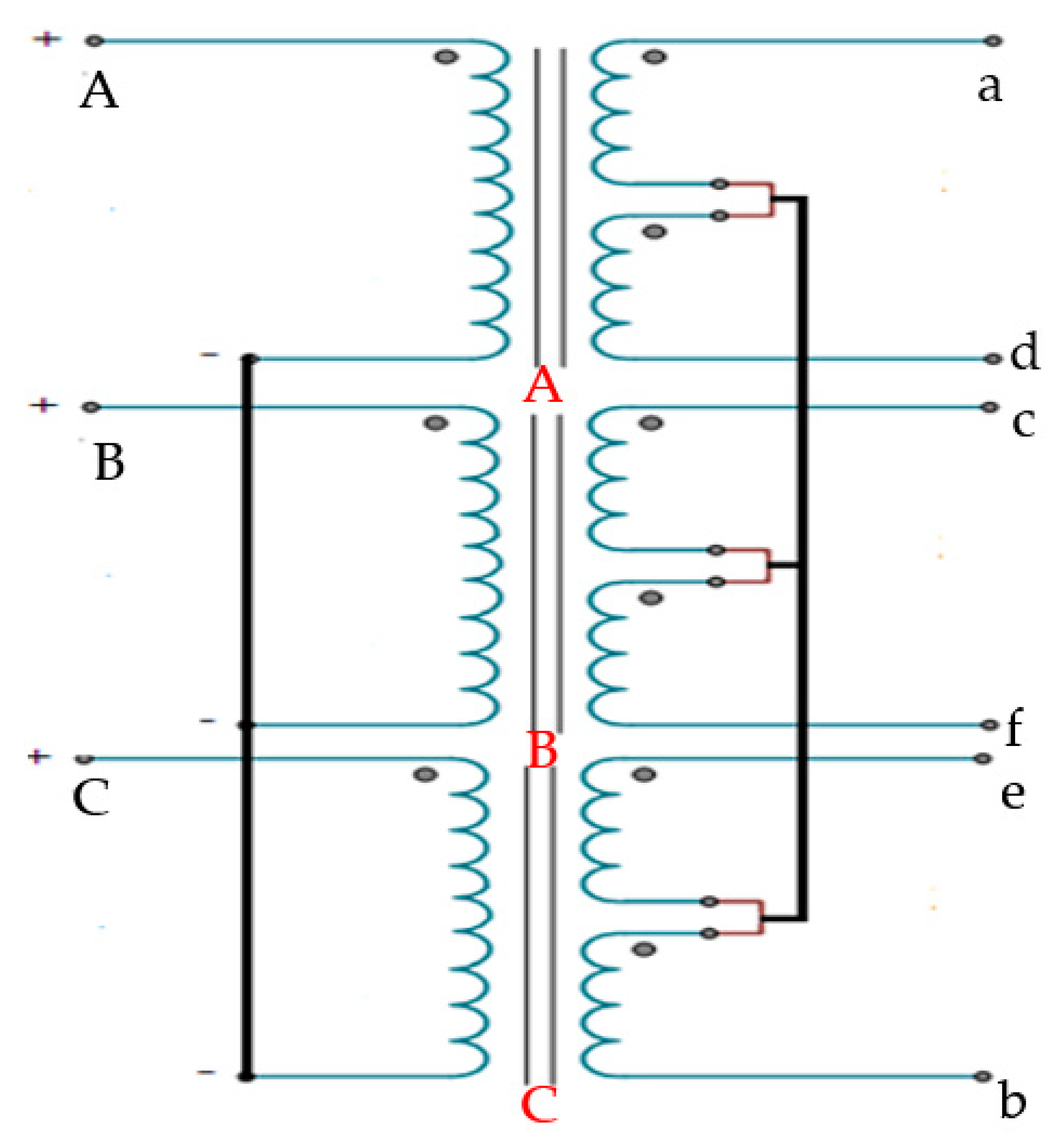
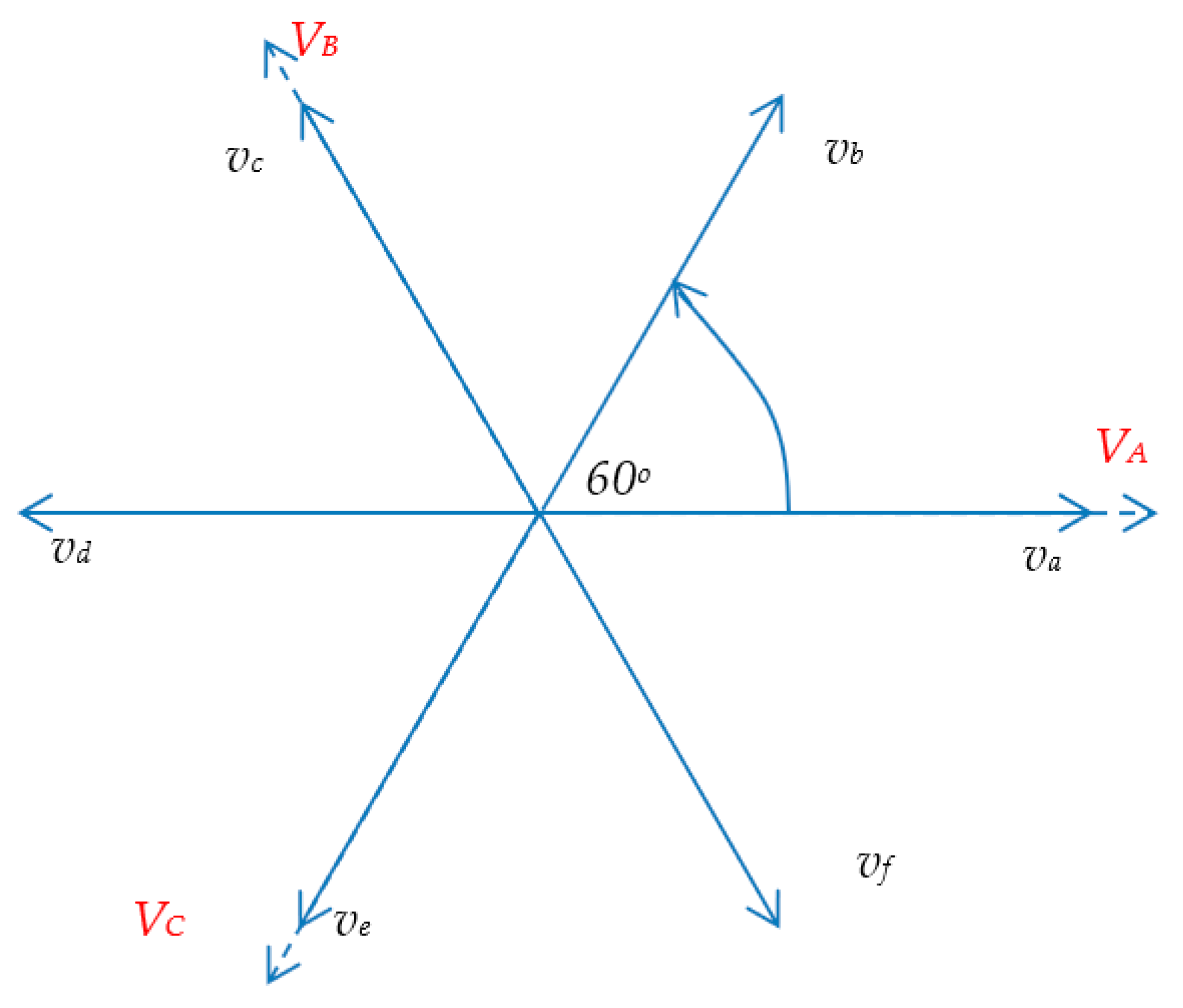
2. Modelling, Winding Arrangement, and Calculation of Six-Phase Transformer
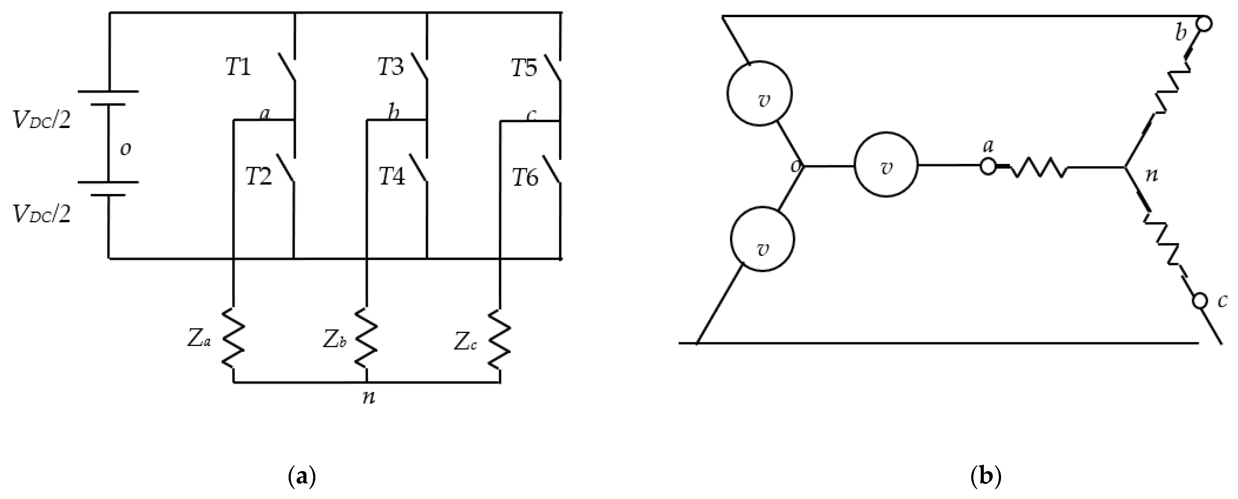
3. Modeling of Three-Phase Inverter
4. Model of Six-Phase Induction Motor
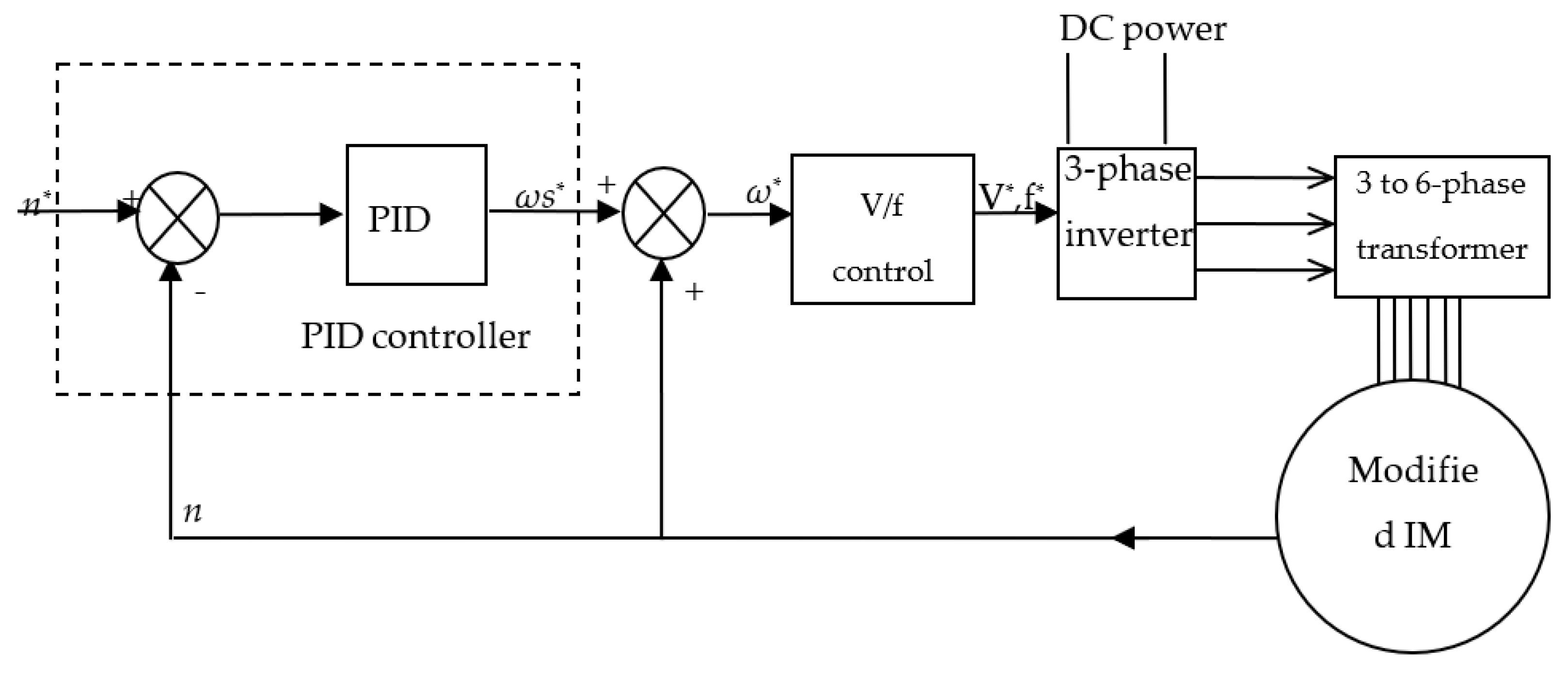
5. Proposed Control Strategy
6. Implementation of Six-Phase Induction Motor
6.1. Experimental Setup
- (1)
- Control board stage (three-phase inverter).
- (2)
- Power stage.
- (3)
- Design and implementation of 3300 VA, 220/220 V, prototype three-to-six phase transformer [41].
- (4)
- A3-hp, 380 V, 2-pole three-phase IM prototype modified six-phase induction motor [41].
- (5)
- Measuring instruments.
- (6)
- Electrical break (centrifugal pumping load).
6.2. Studied Cases
6.3. Simulation and Experimental Results
7. Conclusions
Author Contributions
Funding
Acknowledgments
Conflicts of Interest
References
- Abdelwanis, M.I.; Selim, F. A sensorless six-phase induction motor driving a centrifugal pump system. In Proceedings of the 19th International Middle-East Power Systems Conference, MEPCON 2017, Cairo, Egypt, 19–21 December 2017. [Google Scholar]
- Nanoty, P.A.; Chudasama, P.A.R. Testing of Designed Developed Prototype Six Phase Induction Motor and Analysis of Problems Faced in Actual Development. IOSR J. 2014, 2014, 1–6. [Google Scholar]
- Taheri, A.; Rahmati, A.; Kaboli, S. Comparison of efficiency for different switching tables in six-phase induction motor DTC drive. J. Power Electron. 2012, 12, 128–135. [Google Scholar] [CrossRef] [Green Version]
- Nanoty, A.; Chudasama, A.R. Design, Development of Six Phase Squirrel Cage Induction Motor and its Comparative Analysis with Equivalent Three Phase Squirrel Cage Induction Motor Using Circle Diagram. Int. J. Emerg. Technol. Adv. Eng. 2013, 3, 731–737. [Google Scholar]
- Singh, G.K. Multi-phase induction machine drive research—A survey. Electr. Power Syst. Res. 2002, 61, 139–147. [Google Scholar] [CrossRef]
- Paredes, J.; Prieto, B.; Satrústegui, M.; Elósegui, I.; González, P. Improving the Performance of a 1-MW Induction Machine by Optimally Shifting from a Three-Phase to a Six-Phase Machine Design by Rearranging the Coil Connections. IEEE Trans. Ind. Electron. 2021, 68, 1035–1045. [Google Scholar] [CrossRef]
- Heidari, H.; Rassõlkin, A.; Vaimann, T.; Kallaste, A.; Taheri, A.; Holakooie, M.H.; Belahcen, A. A novel vector control strategy for a six-phase induction motor with low torque ripples and harmonic currents. Energies 2019, 12, 1102. [Google Scholar] [CrossRef] [Green Version]
- Huang, J.; Kang, M.; Yang, J.Q.; Jiang, H.B.; Liu, D. Multiphase machine theory and its applications. In Proceedings of the 2008 International Conference on Electrical Machines and Systems, Wuhan, China, 17–20 October 2008; pp. 1–7. [Google Scholar]
- Singh, G.K.; Pant, V. Analysis of a multiphase induction machine under fault condition in a phase-redundant A.C. drive system. Electr. Mach. Power Syst. 2000, 28, 577–590. [Google Scholar] [CrossRef]
- Abdel-Khalik, A.S.; Abdel-Majeed, M.S.; Ahmed, S. Effect of Winding Configuration on Six-Phase Induction Machine Parameters and Performance. IEEE Access 2020, 8, 223009–223020. [Google Scholar] [CrossRef]
- Mandal, S. Performance Analysis of Six-Phase Induction Motor. Int. J. Eng. Res. Technol. 2015, 4, 589–593. [Google Scholar]
- Nagaraj, P.; Kannan, V.; Santhi, M. Modified Multiphase Induction Motor with High Starting Torque. Int. J. Innov. Res. Sci. Eng. Technol. 2014, 3, 519–522. [Google Scholar]
- Ai, Y.; Wang, Y.; Kamper, M.J. Torque performance comparison from three-phase with six-phase induction machine. In Proceedings of the 2009 International Conference on Mechatronics and Automation, Changchun, China, 9–12 August 2009; pp. 1417–1421. [Google Scholar]
- Renukadevi, G.; Rajambal, K. Generalized d-q Model of n-Phase Induction Motor. Int. J. Electr. Comput. Eng. 2012, 6, 1066–1075. [Google Scholar]
- Abdelwanis, M.I.; El-Sehiemy, R.A. A Fuzzy-Based Controller of a Modified Six-Phase Induction Motor Driving a Pumping System. Iran. J. Sci. Technol.-Trans. Electr. Eng. 2019. [Google Scholar] [CrossRef]
- Okpo, E.E.; Okoro, O.I.; Awah, C.C.; Akuru, U.B. Performance Evaluation of 5.5 kW Six-Phase Asynchronous Motor. In Proceedings of the 2019 IEEE PES/IAS PowerAfrica, Abuja, Nigeria, 20–23 August 2019; pp. 639–644. [Google Scholar]
- Lyra, R.O.C. Torque density improvement in a six-phase induction motor with third harmonic current injection. IEEE Trans. Ind. Appl. 2002, 38, 1351–1360. [Google Scholar] [CrossRef]
- Nanoty, A.R.; Chudasama, A. Control of Designed Developed Six Phase Induction Motor. Int. J. Electromagn. Appl. 2012, 2, 77–84. [Google Scholar] [CrossRef]
- Bachir, G.; Bendiabdellah, A. Scalar control for six phase matrix converter fed double star induction motor. Adv. Electr. Comput. Eng. 2010, 10, 121–126. [Google Scholar] [CrossRef]
- Nabi, H.P.; Dadashi, P.; Shoulaie, A. A novel structure for vector control of a symmetrical six-phase induction machine with three current sensors. In Proceedings of the 2011 10th International Conference on Environment and Electrical Engineering, Rome, Italy, 8–11 May 2011; pp. 1–5. [Google Scholar]
- Maia, A.C.N.; Jacobina, C.B. Six-phase machine drive system based on three three-leg converters. In Proceedings of the 2013 Brazilian Power Electronics Conference, Gramado, Brazil, 27–31 October 2013; pp. 915–920. [Google Scholar]
- Kali, Y.; Saad, M.; Doval-Gandoy, J.; Rodas, J. Discrete Terminal Super-Twisting Current Control of a Six-Phase Induction Motor. Energies 2021, 14, 1339. [Google Scholar] [CrossRef]
- Alam, M.S.; Khan, M.R.; Kumar, A. Stability analysis of a five phase closed loop induction motor drive system using D-Partition technique. In Proceedings of the 2016 International Conference on Electrical, Electronics, and Optimization Techniques (ICEEOT), Chennai, India, 3–5 March 2016; pp. 1298–1302. [Google Scholar]
- Wu, D.; Chang, C.S.; Fang, Y.; Bai, H. Performance improvement of V/f induction -motor control in the low-frequency range. In Proceedings of the 8th International Conference on Advances in Power System Control, Operation and Management (APSCOM 2009), Hong Kong, China, 8–11 November 2009; pp. 1–6. [Google Scholar]
- Itoh, J.I.; Nakajima, Y.; Kato, M. Maximum torque per ampere control method for IPM Synchronous Motor based on V/f control. In Proceedings of the 2013 IEEE 10th International Conference on Power Electronics and Drive Systems (PEDS), Kitakyushu, Japan, 22–25 April 2013; pp. 1322–1327. [Google Scholar] [CrossRef]
- Agarlita, S.C.; Coman, C.E.; Andreescu, G.D.; Boldea, I. Stable V/f control system with controlled power factor angle for permanent magnet synchronous motor drives. IET Electr. Power Appl. 2013, 7, 278–286. [Google Scholar] [CrossRef]
- Padmanaban, S.; Grandi, G.; Blaabjerg, F.; Olorunfemi Ojo, J.; Wheeler, P.W. Power sharing algorithm for vector controlled six-phase AC motor with four customary three-phase voltage source inverter drive. Eng. Sci. Technol. Int. J. 2015, 18, 408–415. [Google Scholar] [CrossRef] [Green Version]
- Abdelwanis, M.I.; Selim, F.; El-Sehiemy, R.A. An efficient sensorless slip dependent thermal motor protection schemes applied to submersible pumps. Int. J. Eng. Res. Afr. 2015. [Google Scholar] [CrossRef]
- Abd-Elwanis, M.I.; Selim, F.F. A Sensorless Controller of Submersible Motors Fed From Photovoltaic System. In Proceedings of the 17th International Middle-East Power System Conference, Mansoura, Egypt, 15–17 December 2015. [Google Scholar]
- Taheri, A.; Ren, H.P.; Holakooie, M.H. Sensorless Loss Model Control of the Six-Phase Induction Motor in All Speed Range by Extended Kalman Filter. IEEE Access 2020, 8, 118741–118750. [Google Scholar] [CrossRef]
- Shawier, A.; Habib, A.; Mamdouh, M.; Abdel-Khalik, A.S.; Ahmed, K.H. Assessment of Predictive Current Control of Six-Phase Induction Motor with Different Winding Configurations. IEEE Access 2021, 9, 81125–81138. [Google Scholar] [CrossRef]
- Levi, E.; Bojoi, R.; Profumo, F.; Toliyat, H.A.; Williamson, S. Multiphase induction motor drives-a technology status review. IET Electr. Power Appl. 2007, 1, 643–656. [Google Scholar] [CrossRef] [Green Version]
- Aziz, G.A.A.; Amin, M.; El-Sousy, F.F.M.; Gaber, K. MRAS-based Super-Twisting Sliding-Mode Observer with DTC of Six-Phase Induction Motor for Ship Propulsion Application. In Proceedings of the 2020 IEEE Industry Applications Society Annual Meeting, Detroit, MI, USA, 3–4 March 2020; pp. 1–7. [Google Scholar]
- Daoud, M.I.; Massoud, A.; Abdel-Khalik, A.; Ahmed, S. An asymmetrical six-phase induction machine-based flywheel energy storage system using modular multilevel converters. In Proceedings of the 19th International Conference on Electrical Machines and Systems, Chiba, Japan, 13–16 November 2017; pp. 1–6. [Google Scholar]
- Abdelwanis, M.I.; Abaza, A.; El-Sehiemy, R.A.; Ibrahim, M.N.; Rezk, H. Parameter Estimation of Electric Power Transformers Using Coyote Optimization Algorithm with Experimental Verification. IEEE Access. 2020, 8, 1–9. [Google Scholar] [CrossRef]
- Chen, X. Three-phase/six-phase conversion autotransformers. IEEE Trans. Power Deliv. 2003, 18, 1554–1561. [Google Scholar] [CrossRef]
- Al-Ammari, R.; Iqbal, A.; Khandakar, A.; Rahman, S.; Padmanaban, S. Systematic implementation of multi-phase power supply (Three to six) conversion system. Electron 2019, 8, 109. [Google Scholar] [CrossRef] [Green Version]
- Iqbal, A.; Moinuddin, S.; Khan, M.R.; Ahmed, S.M.; Abu-Rub, H. A novel three-phase to five-phase transformation using a special transformer connection. IEEE Trans. Power Deliv. 2010, 25, 1637–1644. [Google Scholar] [CrossRef]
- Moinoddin, S.; Iqbal, A.; Abu-Rub, H.; Khan, M.R.; Ahmed, S.M. Three-Phase to Seven-Phase Power Converting Transformer; IEEE: Piscataway, NJ, USA, 2012; Volume 27, pp. 757–766. [Google Scholar]
- Sadiki, L.; ElHani, S.; Ouachtouk, I.; Guedira, S. Optimized Feed of Six Phase Induction Machine Using Special Transformers. In Proceedings of the 2020 International Conference on Electrical and Information Technologies, Rabat-Salé, Morocco, 4–7 March 2020; pp. 2020–2022. [Google Scholar]
- Abdelwanis, M.I.; Sehiemy, R.A.; Hamida, M.A. Hybrid optimization algorithm for parameter estimation of poly-phase induction motors with experimental verification. Energy AI 2021, 5, 1–15. [Google Scholar] [CrossRef]
- Barrero, F.; Duran, M.J. Recent advances in the design, modeling, and control of multiphase machines—Part I. IEEE Trans. Ind. Electron. 2016, 63, 449–458. [Google Scholar] [CrossRef]
- Duran, M.J.; Barrero, F. Recent advances in the design, modeling, and control of multiphase machines—Part II. IEEE Trans. Ind. Electron. 2016, 63, 459–468. [Google Scholar] [CrossRef]
- Renukadevi, G.; Rajambal, K. Modeling and analysis of multi-phase inverter fed induction motor drive with different phase numbers. WSEAS Trans. Syst. Control 2013, 8, 73–80. [Google Scholar]
- Heidari, H.; Rassõlkin, A.; Holakooie, M.H.; Vaimann, T.; Kallaste, A.; Belahcen, A.; Lukichev, D.V. A parallel estimation system of stator resistance and rotor speed for active disturbance rejection control of six-phase induction motor. Energies 2020, 13, 1121. [Google Scholar] [CrossRef]
- Shata, A.M.; Abdel-khalik, A.S.; Member, S.; Hamdy, R.A.; Member, S.; Mostafa, M.Z. Improved Mathematical Modeling of Six Phase Induction Machines Based on Fractional Calculus. IEEE Access 2021, 9, 53146–53155. [Google Scholar] [CrossRef]
- Boldea, I.; Moldovan, A.; Tutelea, L. Scalar V/f and I-f control of AC motor drives: An overview. In Proceedings of the Joint International Conference—ACEMP 2015: Aegean Conference on Electrical Machines and Power Electronics, OPTIM 2015: Optimization of Electrical and Electronic Equipment and ELECTROMOTION 2015: International Symposium on Advanced Electromechanical Moti, Side, Turkey, 2–4 September 2015; pp. 8–17. [Google Scholar]
- Munoz-Garcia, A.; Lipo, T.A.; Novotny, D.W. A New Induction Motor V/f Control Method Capable of High-Performance Regulation at Low Speeds. IEEE Trans. Ind. Appl. 1998, 34, 813–819. [Google Scholar] [CrossRef] [Green Version]
- Shah, D.; Nandi, S. Analytical approach to design of slip-controller for constant Volts/Hz scheme induction motor drive using motor name-plate details. In Proceedings of the Canadian Conference on Electrical and Computer Engineering, Vancouver, BC, Canada, 5–8 May 2007; pp. 393–396. [Google Scholar]


| Period No. | Period (min.) | Description | |
|---|---|---|---|
| From | To | ||
| 1 | 0 | 0.35 | Starting instant |
| 2 | 0.35 | 1 | Rated operation (2800 rpm) |
| 3 | 1 | 2 | Low-speed operation (2000 rpm) |
| 4 | 2 | 3 | More speed reduction (1000 rpm) |
| 5 | 3 | 4 | Rated operating period (2800 rpm) |
| Values | Reading | Values | Reading |
|---|---|---|---|
| Vin (V) | 220 | Vo1 (V) | 220 |
| Vo2 (V) | 220 | I (A) | 5 |
| Parameter | Value | Parameter | Value |
|---|---|---|---|
| Lls (H) | 0.0409 | Rr (Ω) | 8.097 |
| Lm (H) | 0.849 | J (kg·m2) | 0.003 |
| Llr (H) | 0.0409 | p (poles) | 2 |
| Rs Ω | 12 | Vph (V) | 220 |
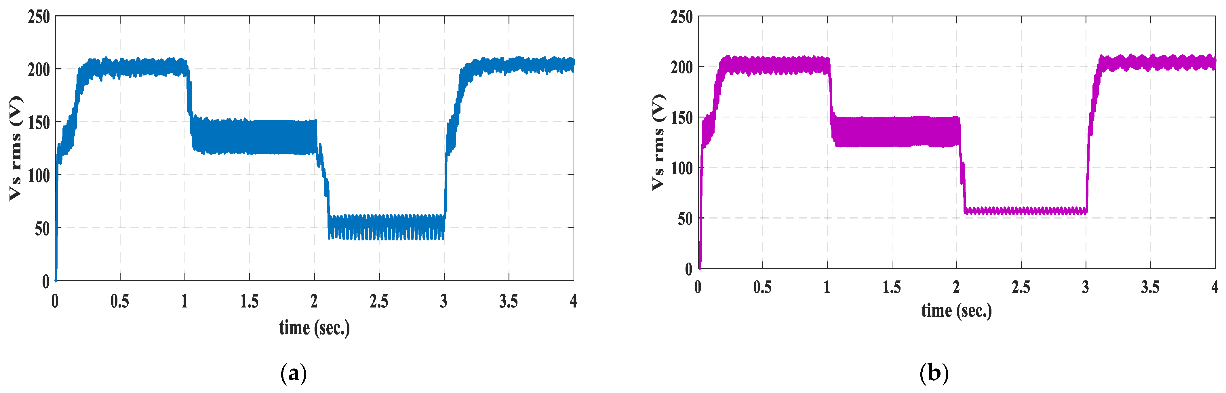
| Period | Speed (rpm) | ||
|---|---|---|---|
| State | TITST | SI | |
| 1 | Steady state error | 30 | 55 |
| Oscillation range | 25 | 25 | |
| 2 | Steady state error | 35 | 35 |
| Oscillation range | 30 | 25 | |
| 3 | Steady state error | 50 | 55 |
| Oscillation range | 8 | 240 | |
| 4 | Steady state error | 20 | 20 |
| Oscillation range | 35 | 25 | |
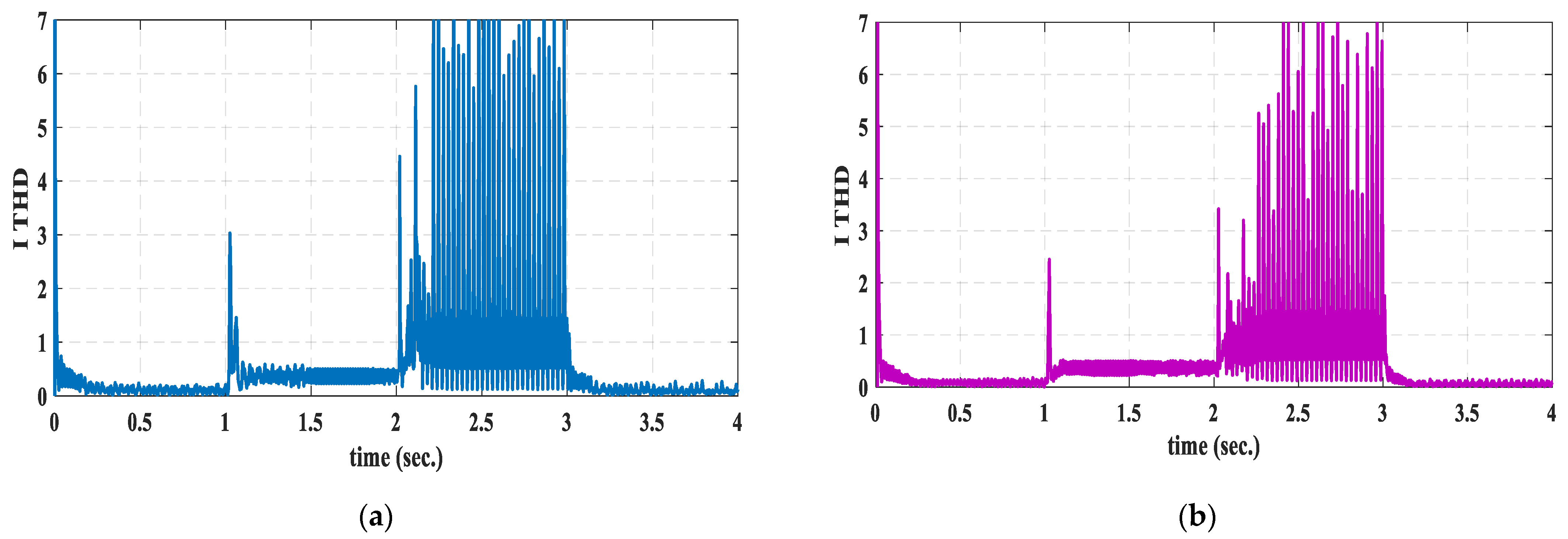
| Period | State | Current (A) | THD (%) of Current | THD (%) of Voltage | |||
|---|---|---|---|---|---|---|---|
| TITST | SI | TITST | SI | TITST | SI | ||
| 1 | Starting value | 5.2 | 5.72 | 7 | 7 | 0.8 | 3 |
| Oscillation range | 0.3 | 1.45 | 0.1 | 0.1 | 0.08 | 0.1 | |
| Mean | 1.05 | 1.02 | 0.55 | 0.5 | 0.11 | 0.2 | |
| 2 | Starting value | 1.85 | 1.65 | 3 | 2.5 | 0.62 | 0.45 |
| Oscillation range | 0.55 | 0.5 | 0.38 | 0.4 | 0.35 | 0.35 | |
| Mean | 0.85 | 0.9 | 0.4 | 0.35 | 0.3 | 0.2 | |
| 3 | Starting value | 2.92 | 2.52 | 0.41 | 0.35 | 1.4 | 35 |
| Oscillation range | 0.7 | 1.5 | 1 | 1 | 0.8 | 6 | |
| Mean | 0.7 | 0.7 | 7 | 7 | 1 | 35 | |
| 4 | Starting value | 4.27 | 4.66 | 1.3 | 2 | 0.5 | 3 |
| Oscillation range | 0.3 | 0.2 | 0.5 | 0.7 | 0.06 | 0.8 | |
| Mean | 1.05 | 1.05 | 0.35 | 0.35 | 0.09 | 0.1 | |
Publisher’s Note: MDPI stays neutral with regard to jurisdictional claims in published maps and institutional affiliations. |
© 2021 by the authors. Licensee MDPI, Basel, Switzerland. This article is an open access article distributed under the terms and conditions of the Creative Commons Attribution (CC BY) license (https://creativecommons.org/licenses/by/4.0/).
Share and Cite
Abdelwanis, M.I.; Rashad, E.M.; Taha, I.B.M.; Selim, F.F. Implementation and Control of Six-Phase Induction Motor Driven by a Three-Phase Supply. Energies 2021, 14, 7798. https://doi.org/10.3390/en14227798
Abdelwanis MI, Rashad EM, Taha IBM, Selim FF. Implementation and Control of Six-Phase Induction Motor Driven by a Three-Phase Supply. Energies. 2021; 14(22):7798. https://doi.org/10.3390/en14227798
Chicago/Turabian StyleAbdelwanis, Mohamed I., Essam M. Rashad, Ibrahim B. M. Taha, and Fathalla F. Selim. 2021. "Implementation and Control of Six-Phase Induction Motor Driven by a Three-Phase Supply" Energies 14, no. 22: 7798. https://doi.org/10.3390/en14227798