Article

Influence of Hydrogen-Containing Fuels and Environmentally Friendly Lubricating Coolant on Nitrogen Steels’ Wear Resistance for Spark Ignition Engine Pistons and Rings Kit Gasket Set

by
Alexander Balitskii
1,2,*,
Valerii Kolesnikov
1,3,
Karol F. Abramek
2,
Olexiy Balitskii
4,
Jacek Eliasz
2,
Havrylyuk Marya
1,
Lyubomir Ivaskevych
1 and
Ielyzaveta Kolesnikova
5
1
Department of Strength of the Materials and Structures in Hydrogen-Containing Environments, Karpenko Physico-Mechanical Institute, National Academy of Sciences of Ukraine, 79-601 Lviv, Ukraine
2
Department of Mechanical Engineering and Mechatronics, West Pomeranian University of Technology, 70-310 Szczecin, Poland
3
Department of Production Technology and Professional Education, Taras Shevchenko National University of Lugansk, 92-703 Starobilsk, Ukraine
4
Department of System Design, Lviv Ivan Franko National University, 79-005 Lviv, Ukraine
5
Department of Social Sciences, Ukrainian Catholic University, I. Svientsitskoho Street, 17, 79-011 Lviv, Ukraine
*
Author to whom correspondence should be addressed.
Energies 2021, 14(22), 7583; https://doi.org/10.3390/en14227583
Submission received: 25 October 2021 / Revised: 6 November 2021 / Accepted: 8 November 2021 / Published: 12 November 2021

Abstract

:
In this study, modern nitrogen steels used for the manufacture of rings for Honda engines (70CC, 90CC, CRF70F, XL70, XR70, C70, CT70, ATC70, CL70) as well as other transport tribotechnical units was investigated. Due to the present ecological situation in the world, new environmentally friendly lubricating fluids for nitrogen steels’ tribotechnical units and surface treatments have been proposed. The results of tribotechnical tests are presented in the form of diagrams, graphs and step polynomials obtained by mathematically describing the changes in wear intensity when the load changes for different lubricating fluids. Friction pairs were compared with ShellHF-E 46 (synthetic lubricating fluid), ShellHF-R (biological origin) and lubricating and cooling liquids with 1%, 3% and 5% vegetable oil concentrations. In tribocoupling it was found that hydrogen diffuses into the metal because the tribodestruction of lubricating coolants plays an active role in the destruction of friction surfaces.

1. Introduction

The use of lubricating cooling liquids (LCLs) in tribo joints enables a reduction in the intensity of wear. On the other hand, use of LCL improves cutting and machining technological processes. For a certain period of time, lubricants were based on petroleum products. At the present time their use is problematic in terms of further disposal [1]. Moreover, a separate problem is that most metal structures and equipment items that come into contact with petroleum products (including lubricants) are made from steel and operated at an ambient temperature (from −50 °C to +50 °C) in different regions of our planet. When metals and alloys come into contact with pure hydrocarbons (CnHm), they do not react with them. Paper [2] describes such a complex phenomenon of pollution to demonstrate its importance, as the number of failures of steel parts is growing every year. It is important to understand that the corrosion process takes place at the interface of different phases. Water, H2S, corrosion products, ions, phenols, organic acids and other compounds containing sulfur, oxygen and nitrogen dissolved in petroleum products are contaminants responsible for the further destruction of steel components. Therefore, the use of stainless steels in tribo joints can provide additional avoidance of problems with premature failure and prolong the lifetime of the operated components. Despite the higher cost of stainless steels (including high nitrogen steels (HNSs)), they are introduced as tribomaterials [3,4,5]. High nitrogen, high chromium steels are widely not only in modern energy domains. The areas of their application are constantly expanding. Modern production technologies and complex alloying can significantly expand the range of applications for products made from these materials due to hydrogen resistance. Piston rings have as a main function sealing the combustion chamber. Compression rings maintain compression—with worn, broken or stuck rings the engine will lose power or will not start at all; they also increase heat transfer from the piston through the cylinder wall, preventing overheating and scuffing of the piston, and regulate the thickness of the engine oil film on the cylinder (in all four-stroke engines and in two-stroke engines) with separate lubrication [2]. Piston rings are made from high quality gray, ductile iron or HNS. The heat resistance and tensile strength of HNS is higher, but cast iron is cheaper and can be easily run in even without coating. Steel rings are coated with an anti-friction running-in, and often with a hard coating. The top ring is subjected to high nitrogen saturation or use of the HNS, which comes into contact with environmentally friendly tribotechnical compositions. Due to an investigation of the tribotechnical properties it has been established that the HNS can retain a layer of solid lubricant with a layered structure for a long time.
According to the European Directives [6] on environmental liability, aimed at preventing environmental damage and eliminating its consequences, preventing environmental degradation and implementing its consequences is a task directly capable of implementing European Community environmental policy.
During operation, lubricants change their properties [7], so it makes sense to create and explore new, more “environmentally friendly” options. Lubricants are used as an anti-friction and heat absorbing environment and therefore lead to smooth and reliable functions (operations), reduce the risks of frequent failures and thus enhance the durability (life-cycle) of a vehicle. At present, due to worldwide concern with protecting the environment from pollution and the increased prices and depletion of reserve crude oil, there has been growing interest in formulating and applying an alternative solution with the investigation and development of environment-friendly bio-lubricants from natural resources. A bio-lubricant is a renewable and sustainable lubricant that is biodegradable, non-toxic and emits net zero greenhouse gas [8]. To increase the “environmental friendliness” you can use “green oils”. Green oils are characterized by low toxicity, low pollution and biodegradation.
The base oils are mainly polyester, synthetic ether and natural vegetable oil. Additives suitable for green base oils are a prerequisite for the use of green oils [1]. Our own previous studies have shown that lubricating coolants made with the addition of sunflower or rapeseed oils [9] can be successfully used as tribotechnical materials, including in tribo compounds in contact with high-nitrogen steels [10].
At the processing of metals various lubricating and cooling liquids (LCLs) which provide the quality of the made elements of machine-building designs are widely applied. Recently, investigations have been conducted on the possibility of using LCLs to increase the wear resistance of sliding elements of tribocouples, especially heavy machinery (e.g., earthmoving machines, hydraulic drives of coal harvesters, agricultural machinery, metalworking, etc.). Increased lubricating LCL properties are used in the form of aqueous solutions of low concentration, which is important from an economic point of view.

2. State of the Art

There is now a significant transformation in the automotive industry occurring, which is to improve internal combustion engines in order to comply with environmental standards in accordance with EURO 6 (an environmental standard that regulates the content of harmful substances in exhaust gases) [11,12,13]. In its requirements, EURO 6 is close to the EPA10 environmental standard in the United States and the Japanese Post NLT, which has been in effect since 2010. The new European standard will facilitate the harmonized development of future uniform standards (for example EURO 7) [14]. The problem of exhaust gases and air pollution is of great environmental importance, so scientific research is underway to improve and modernize internal combustion engines, including introducing alternative hydrogen-containing fuels [15,16,17,18,19,20,21].
Materials for the manufacture of piston rings are selected taking in to account the antifriction properties and conditions under which the piston rings must work. High elasticity and corrosion resistance are just as important as high resistance to damage under extreme operating conditions. Piston rings are made of high-quality gray or malleable cast iron or alloyed steel [22,23,24]. Heat resistance and strength of steel are higher, but cast iron is cheaper and easier to earn even without coating. From a tribological point of view, gray cast iron and the graphite inclusions contained in it provide optimal properties when working in emergency mode (dry lubrication with graphite).
We have established that high-nitrogen steels can hold a layer of adsorbed layered lubricants on their surfaces for several hours (in the absence of lubrication) [25,26]. This feature is associated with the characteristics of the surface layer formed in a number of technological operations. Therefore, the selection of lubricants for high-nitrogen steel can significantly prolong the operational stability, including in extreme conditions with the disappearance of the protective layer. These properties are especially important when lubrication with engine oil stops and the oil film is already destroyed. In addition, the graphite veins in the ring structure serve as oil reservoirs and counteract the destruction of the oil film under adverse operating conditions. We also found that high-nitrogen steels can hold well on their surface layered coatings, not only of graphite origin, and reduce the intensity of wear [26,27].
Chromium steel with martensitic microstructure and spring steel are used as a structural material. To increase the wear resistance, the surface of the materials is hardened. This is usually done by nitriding. However, as one of the options, you can use directly high-nitrogen steels, which are also increasingly used in other responsible tribotechnical units, including in transport engineering [28,29,30,31,32].
Investigation in the tribotechnical direction allows to assess the state and processes of destruction of materials in different operating conditions, including during setting [33,34,35,36]. Nitrogen steels are used to make rings for Honda 70CC, 90CC, CRF70F, XL70, XR70, C70, CT70, ATC70 and CL70 engines [37]. The set includes a set of pistons and a set of gaskets. Piston rings can be suitable for operation at high speeds and with high loads. Concerning the first piston ring made of nitrogen steel, the process includes a set of pistons and a set of gaskets. The piston rings can be suitable for high speed and high load operation. Concerning the first piston ring with a nitrogen steel: Piston diameter—47 mm; piston height—41.5 mm; piston pin diameter—13 mm; piston pin length—38 mm.
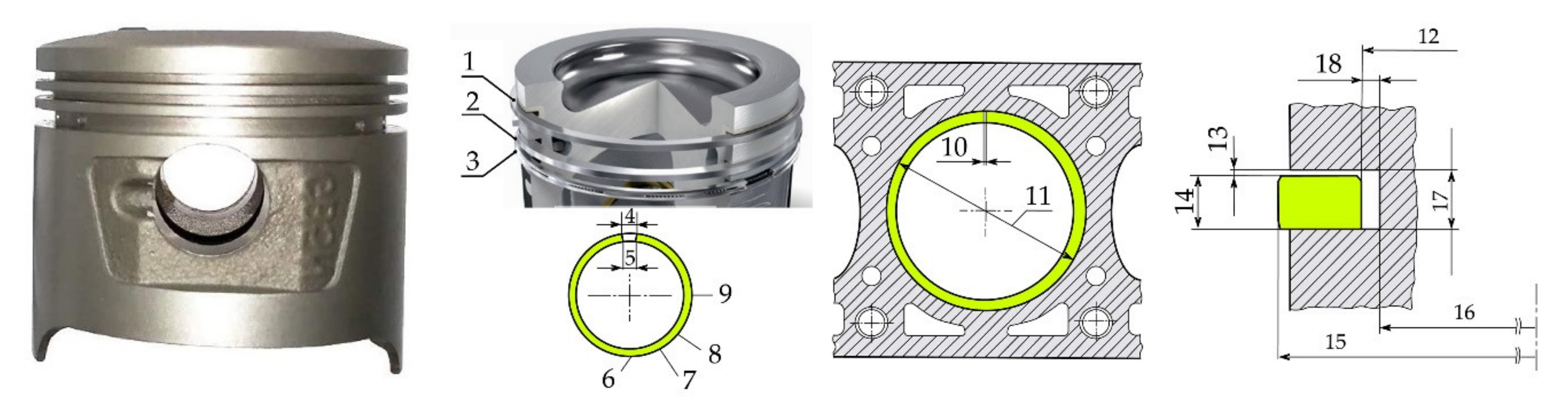
The complex requirements for piston rings cannot be met using only one piston ring. This can only be done with a few piston rings of different types. In modern automotive engine construction, a well-established solution is a combination of a compression piston ring, a combined compression and oil removal piston ring and a separate oil removal piston ring. Pistons with more than three rings are relatively rare today (Figure 1 shows a typical complete set of piston rings).
Cylindrical piston rings are rings with a rectangular cross-section (Figure 2). In such rings, the side surfaces are parallel to each other. This type of piston ring compression is the simplest and most common. Today, rings of this type are used primarily as the first compression ring in all gasoline and sometimes diesel car engines. The presence of internal chamfers and corners causes the rings to twist in the installed (stressed) state. A chamfer or inner corner on the top edge causes a “positive ring twist”.
Tapered rings are used on all types of engines (gasoline and diesel, for cars and trucks) and are usually installed in the second annular groove. These rings serve a dual purpose. They help the compression ring to resist blow-by gases and the oil scraper ring to regulate the oil film thickness. The working surface of the tapered rings is tapered. Depending on the version, the angular deviation of the working surface in comparison with a rectangular ring is from 45 to 60 arc minutes. Due to this shape, the new tapered ring contacts the cylinder surface only along the lower edge. For this reason, in this area, a high mechanical pressure on the surface arises and the desired material removal occurs.
As a result of this planned wear and tear, which occurs during the running-in period, a perfectly rounded lip is formed after only a short period of time, which ensures an optimal seal. Over a period of operation of several hundred thousand km, the working surface of the ring loses its conical shape, and the conical ring begins to function as a rectangular ring. Now with the properties of a rectangular ring, the former tapered ring still provides a reliable seal.
Due to the fact that gases exert pressure on the ring also from the front (due to the penetration of gases into the gap between the cylinder and the working surface of the piston ring), the increase in the effect of gas pressure is somewhat reduced. Due to this, during the running-in of the ring, the contact pressure and the degree of wear are slightly reduced. Tapered rings not only function as compression piston rings, but also have good oil scraper properties. This is facilitated by the inwardly displaced upper edge of the ring.
When the piston moves up, from bottom to top dead center, the ring slides over the oil film. Under the action of hydrodynamic forces (formation of an oil wedge), the ring slightly moves away from the cylinder surface. When the piston moves in the opposite direction, the edge of the ring penetrates deeper into the oil film and thus removes the oil layer, taking it towards the crankcase. In petrol engines, tapered rings are also fitted in the first ring groove. A chamfer or inner corner, relative to the bottom edge, causes negative torsion of the ring [38].
HNS has been used not only for Honda engines, but also for engines that are produced by other companies. The Honda Motor Company Ltd. began its journey with the creation of piston rings and later created the highest quality pistons. HNS have a whole range of properties that allow them to have the required performance characteristics. Tōkai Seiki (Eastern Sea Precision Machine Company) made piston rings working out of the Art Shokai garage [1,16]. After initial failures, Tōkai Seiki began supplying piston rings to Toyota. Toyota’s quality control processes are known as “five whys” and operate under an automated process [1,16,17,18].

3. Problem Formulation

This paper addresses the following issue concerning the problem being solved: The value of nitrogen steels’ wear for rings concerning additional industrial and ecological CLC products.

4. Materials and Experimental Procedure

4.1. Tribotechnical Investigations on the Friction Machine

Wear resistance was studied on a friction machine SMT-1 (2070). The sliding speed of the lower roller is 1480 rpm, and the upper is 1240 rpm (slip—15%). The error of the speedometer of the lower sample is ±3%. Before studying, the alloys were worked and the load was changed from smaller to larger (the indicator was a constant moment of friction). Tribotechnical studies were also carried out on a 2070 SMT-1 testing machine. There occurred abrasion of a pair of samples pressed against each other by force P. During operation, the friction moment was measured on the lower sample. The technical characteristics of instruments’ testing machines 2070 SMT-1 were: Frequency of rotation of the shaft of the lower sample 75 min−1–1500 min−1. Ranges for measuring the frequency of rotation of the lower sample shaft of the device testing machine 2070 SMT-1 were: Range A—75 min−1 to 750 min−1; range B—150 min−1 to 1500 min−1; the error of the measurement of the frequency of rotation of the shaft of the lower sample was ±3%; the unit price of the smallest category of the counter of the total number of revolutions of the shaft of the lower sample was 100 rpm; the error of the counter of the total number of revolutions of the shaft of the lower sample of the device testing machine 2070 SMT-1 ± 100 rpm. Maximum permissible frictional moment: For samples (disk–disk) in the range of revolutions A and B and for samples (shaft–sleeve) and (disk–block) in the range of revolutions A—20 Nm; for samples (shaft–sleeve) and (disk–block) in the range of revolutions B—10 Nm. Ranges of friction torque measurement of the device testing machine 2070 SMT-1: Range I—1 Nm to 10 Nm; range II—2 Nm to 20 Nm. The limit of the permissible value of the standard deviation of the random component of the reduced error of the friction torque meter of the device testing machine 2070 SMT-1 in the static loading mode—1%. Ranges of force measurement on samples: Range I—for samples (disk–disk) and (disk–pad)—200 N to 2000 N; range II—for samples (shaft–sleeve)—500 N to 5000 N. The limit of the permissible value of the standard deviation of the random component of the reduced error of the force meter in the mode of static loading of the device testing machine 2070 SMT-1—1%; slip coefficients of samples (disk–disk) with the same diameters—0% ± 2%, 10% ± 2%, 15% ± 2%, 20% ± 2%; power consumption—4.5 kW.

4.2. The Investigated Steels

The lower roller (42 mm in diameter) is made of steel 45 (alloy N 1) with a hardness of 55 HRC (designation according to DIN), and the upper roller is made of high-nitrogen steel with a hardness of 52 to 60 HRC (alloy N2 (type P 900)) (chemical composition is shown in Table 1). The elemental composition of the studied steels was performed on a scanning electron microscope EVO 40XVP with system micro-X-ray spectral analysis on energy dispersion X-ray spectrometer INCA ENERGY 350. Moreover, for the investigated steels the technical documentation with records of limits of quantity of alloying elements was provided.
High-nitrogen steels are made of electrodes smelted in an arc furnace, which are remelted in electroslag remelting plants at high pressure to improve purity. After turning the workpieces, the samples are subjected to diffusion annealing, and then cold hardening. Then they are annealed to relieve stress and are processed. Cold plastic deformation of the samples can reach up to 60%. An austenitic metal matrix—with a microhardness of 4.4 to 5.2 GPa—was recorded in the microstructure of P900 steel.

4.3. Steels Phase Composition Examination

The friction surfaces were examined on an electron microscope EVO-40XVP with a microanalysis system INCA Energy 350. X-ray diffraction analysis was performed on a DRON-2 installation (Cu–Kα, 40 kV, 20 mA) on the monochrome irradiation Cu-Kα, with scanning step 0.05° and velocity (1–10)° per min. Spectra identification was carried out using ASTM data. Metallographic studies and measurements of the microhardness of the surface layer were performed on a Neophot 2 microscope.

4.4. Lubricating Cooling Liquids

Vegetable oils were used to develop effective and environmentally friendly lubricating and cooling liquid (LCL). Vegetable oils are mainly triglycerides, triple esters of long chain carboxylic (fatty) acids with glycerol. They are biodegradable and safe for the environment.
Carboxylic acids, which are part of vegetable oils, form salts that have certain anti-corrosion properties [39,40,41]. Three ethanol amine (TEA) was used as vegetable oil modifier. The main reaction centers of the selected substances are unpaired bonds with mobile π-electrons and nitrogen, which cause their high adsorption and protective properties.
The composition and physico-chemical parameters of rapeseed oils are presented in Table 2 and Table 3. Samples of LCL used in industry were selected for investigations: On oil ET-2 TU U 00152365.133-2001 [42,43,44,45,46,47] (LCLn) and new synthesized LCL based on rapeseed (LCLr) oil.

4.5. Transesterification of Rapeseed Oil TEA

Transesterification of rapeseed oil TEA was carried out in the presence of an aqueous solution of potassium hydroxide, using the raw material, the characteristics of which are given in Table 4. Transesterification of triglycerides of TEA oil takes place gradually: (1) Saponification of triglycerides of oil with caustic potassium; (2) hydrolysis and saponification of triglycerides of TEA oil; (3) alcoholysis of triglycerides of TEA oil in the the presence of methyl alcohol as a catalyst in their mass ratio of 4:1.5:1 at 95–125 °C.
Samples of LCL concentrates [46,47] were obtained by mixing an emulsifier formed by the interaction of rapeseed oil with TEA in the presence of potassium hydroxide, methyl alcohol with neonol and rapeseed oil as a base.

5. Results and Discussions

5.1. The Results of Tribotechnical Tests

The results of tribotechnical tests are shown in Figure 3, Figure 4, Figure 5, Figure 6 and Figure 7. Step polynomials (Figure 6 and Figure 8) are also obtained, which mathematically describe the change in wear intensity when the load changes for different lubricating fluids.
To conduct a tribotechnical investigation, steel 45 was selected as a reference; all the obtained values were compared with it. HNS was chosen because it has high performance. For the upper piston rings steels with high nitrogen content were used. One of the key problems for piston rings is that they have an increased number of seizures and burrs during operation. The use of viscose nitrogen steels together with the selection of various technological fluids allows to significantly expand the range of occurrence of such phenomena as settings and burrs.
Tribological tests were carried out in accordance with GOST 23.224-86 and normative documents: Products’ wear resistance assurance, reestablished machine parts; experimental evaluation of wear resistance ability. To determine the tribotechnical characteristics of materials, rollers were made from steels 45, P900 with various radii.
As we can see, the friction pair had the lowest wear where Shell HF-E 46 (which is a synthetic lubricating fluid) was used in tribocoupling, followed by Shell HF-R (biological origin). Lubricating fluids synthesized by authors occupy from three up to five places.
Among the environmentally friendly lubricating coolants that were tested LCLr with a concentration of 3%, then 5% and 1% had the least wear friction pairs. Oils were used because preliminary tests were carried out, which showed that exceeding the concentration of 5% reduces the tribomechanical properties. Figure 7 shows the spectra (with energy dispersion) of the characteristic X-ray radiation of the surface elements of high-nitrogen steel, which show that a protective layer containing oxygen is formed on the friction surface. The appearance of the friction surface indicates the absence of thermal settings and “breakouts” from the friction surface. From the surface there was a detachment of wear particles, which had a petal appearance.

5.2. The Results of Thermogravimetric Analysis

Thermogravimetric tests proceeded according to the methodology described in [46]. In the conditions of increasing loading and also increasing sliding speed there can be a tribodestruction of lubricating cooling liquid. Due to the increase in temperature and aging, LCL may lose its lubricating characteristics, and therefore we conducted research on thermogravimetric analysis. The objects of research were LCLr and LCLn in the form of concentrates, as the working fluids contain only 3% (wt.) concentrate in water, which means that thermal oxidation processes occur only after evaporation of the aqueous medium.
The results of the complex thermogravimetric analysis of the samples are contained in Table 5, and the thermograms of the samples are presented in Figure 8 and Figure 9.
Thermogravimetric (TG) curves, which are presented in Figure 8, show the loss of mass of the samples during heating, differential thermogravimetric (DTG) curves correspond to the dependence of the rate of loss of mass of samples on temperature, differential thermal analysis (DTA) corresponds to the temperature difference observed between sample and standard at the corresponding temperature [46,47].
The appearance of the exothermic effect recorded on the DTA curve of the sample LCLr in the temperature range 145–235 °C, which is accompanied by a slight loss of mass on the TG curve, corresponds to the processes of thermooxidative destruction of triglycerides that are part of the sample. According to the results of thermal analysis, thermal oxidative destruction of hydrocarbons that are part of the samples occurs in the temperature range 170–310 °C. It is accompanied by significant weight loss (TG curve) and the appearance of an exothermic effect (DTA curve).
The beginning and end of the stage of destruction of the samples was determined by fracture on the DTG curve. The temperature at the beginning of the destruction corresponded to the temperature at which the rate of loss of mass of the sample, determined by the DTG curve, was 0.1% per minute. The thermolysis process ends with the combustion of pyrolytic residues of the samples, which is accompanied by the appearance of bright exothermic effects recorded on the DTA curves in the temperature range 410–600 °C.
According to [44,45,46,47,48,49] hydrogen can take an active part in the destruction of surfaces, which can be diffused due to tribodestruction with and from lubricating coolants. We were able to establish an increased concentration of hydrogen in the products of cutting, austenitic high-nickel steels, which were formed in contact with the steels that were studied in this work (Table 6).
Most likely, such data can be obtained by studying the wear products of such steels, but for the study on the LECO device it is necessary to obtain more than 3 g. Under lubrication conditions, such experiments must be carried out for a very long time; then we can transfer the data obtained with the cutting products to the wear products.

5.3. Forecast Assessment of LCL Ecological Safety

At the stage of development it is important to forecast the ecological assessment of LCL, which makes it possible to determine the hazard class, the main controlled sanitary and hygienic parameters and the environmental damage to the environment. To determine the ecological safety of LCL, the sanitary-toxicological forecast of their components was calculated. Ecological and sanitary-hygienic assessment of new compositions is characterized by indicators: MPC (maximum permissible concentration) of chemicals in the air of the working area, in the atmospheric air of the settlement, in the water and in the soil (Figure 10). In the absence of reference data on the MPC, the corresponding ASLE (approximately safe levels of exposure) were calculated: Approximate safe levels of exposure to substances in the work area ASLEw.a. and in atmospheric air ASLEa (mg/m3); approximate permissible levels (concentrations, mg/L) in water APLw; products APCpr.; soil APLs; lethal doses LD50; and LC50 mg/kg and mg/L. To calculate the ASLE of organic compounds from the class of esters in the air in the form of a mixture of vapors and aerosols, the calculation of ASLE was carried out according to the formulas in Table 7.
Our compounds belong to the class of esters, so we choose the formula for the calculation:
ASLEw.a. = 0.002 LD50
where LD50 = ASLEw.a./0.002.
In addition, concerning the composition of the raw materials for LCL, the parameters of the raw materials were evaluated; the methodologies were described in [26,27,46]. Physico-chemical properties were tested and prognostic sanitary-toxicological assessment of the studied substances was performed according to the recommendations [50,51,52].
The dependence was used for calculation:
ASLEw.a. = M∙1000/ΣJi, mg/m3
where ΣJi is the sum of the values of biological activity of chemical bonds of atoms in the molecule of matter; M is the molecular weight of the substance, g/mol. The forecast estimation of ecological danger of the synthesized additives is carried out.
LCLr concentrate consists of a base—rapeseed oil—in which the synthesized ester of triethanolamine and neonol are dissolved. Refined rapeseed oil is a food product and therefore, as in the previous case, a forecast estimate was calculated for the synthesized ester.
ΣJi = 45 × (≡C–H) + 19 × (≡C–C≡) + 1 × (>C=C<) +2 × (–O–H) + 3 × (–O–C≡) + 1 × (–O–C≡) + 1 × (=N–C) + 1 × (=C=O)
ΣJi = 45 × 0.8 + 19 × 51.4 + 1 × 451.8 +2 × (−21,648.2) + 3 × 21,987.7 +1 × 6535.3 + 1 × 3266.2 + 1 × (−12,517.8) = 21,415.2
ASLEw.a. = 415 × 103/21,415.2 = 19.38 mg/m3
LD50 = ASLEw.a. × 500 = 9690 mg/kg
lg ASLEa. = 0.62 × lg ASLEw.a. − 1.77 = 0.62 × lg 19.38 − 1.77 = −0.97
ASLEa = 0.107 mg/m3
APLpr = 0.13 × 10⁻²∙ LD50 + 0.76 = 0.13 × 10−2 × 9690+ 0.76 = 13.36 mg/kg
APCpr = 1.23 + 0.48 × lg APLpr = 1.23 + 0.48 × 1.13 = 1.77 mg/kg
lg APLw = 0.61 × lg ASLEw.a. − 1.0 = 0.61 × 1.23 − 1.0 = −0.21
APLw = 0.62 mg/L
The LCL syntheses and influence on the nitrogen steels’ tribotechnical characteristics have been presented on Figure 3, Figure 4, Figure 5, Figure 6, Figure 7, Figure 8, Figure 9 and Figure 10 and discussed in detail in [50,51,52,53,54,55,56,57,58,59,60,61,62,63,64,65,66,67,68,69,70,71,72,73,74,75,76,77,78,79,80,81,82,83,84,85,86]. Based on the analysis of a number of studies [71,72,73,74,75,76,77,78,79,80,81,82,83,84,85,86] and our own results, it is possible to carry out a number of results of tribological tests. Surface damage is largely determined by the lubrication regime and increases with boundary and/or mixed lubrication regimes. In full-film lubrication mode, frictional force is applied, sliding the lubricating film by sliding. Shear stress (and thus frictional force) depends on the rheological properties of the lubricant. However, when contact occurs between the tops of irregularities, “dry” friction (or friction of boundary lubrication) is considered roughly as a type of Coulomb friction, where it has zero value in pure rolling and close to constant value when sliding begins. It should be noted that in both cases, more slip does not necessarily mean more friction. With a rough (boundary) contact or contact with a mixed lubricant, “dry” places will not exert tensile forces on the surface, unless there is some slip, no matter how small, since it will be different from zero. However, “pure rolling” conditions do not exist. In actual contacts, even when flowing under “nominally pure rolling” conditions, there is always a slight displacement, which entails some sliding friction and therefore the possibility of a risk of surface damage. Boundary friction is a very important factor contributing to the appearance of surface microcracks when contact is applied with a boundary or mixed lubricant. Under boundary or mixed lubrication conditions, the lateral roughness layer (in the rolling/sliding direction) is more susceptible to surface damage than the longitudinal layer. Since contact conditions generally relate more to boundary or mixed lubrication conditions, loading dynamics are applied from the dominant rougher surface to the smoother one based on the presence of sliding. Concerning this situation (i.e., rough and smooth surfaces in mutual sliding), a smooth surface “senses” pressure fluctuations (loading microcycles), and all points of a rough surface always experience the same stresses (which are greater in the contacting areas and less in the non-contacting areas).
This example demonstrates that a rough surface has a predominant effect on a smooth surface in the form of varying loads. In real contact, both surfaces will be rough and in motion (with some sliding), but if their roughness is different, the rougher surface will prevail in the application of load microcycles. Thus, a smoother surface will be more susceptible to surface damage if there is some slip and provided that the mechanical properties of both surfaces are the same.

6. Conclusions

  • The effect of rotational speeds on friction and wear durability of nitrogen steels for spark ignition engine pistons and rings kit gasket set under the influence of hydrogen-containing fuels and environmentally friendly lubricating coolants have been established. Results of tribotechnical tests in the form of diagrams, graphs and power polynomials were obtained that mathematically describe the change in wear intensity when the load changes for different lubricating fluids.
  • The lowest wear was in the friction pair where Shell HF-E 46 (which is a synthetic lubricating fluid) was used in tribocoupling, followed by Shell HF-R (biological origin) and then proposed lubricating fluids synthesized on the base of rapeseed oil. It was established that emulsion with 3% rapeseed oil (LCLr) has the best lubricating properties (the least wear friction pairs). Hydrogen, which diffused into nitrogen steel due to the tribodestruction of lubricating coolants, played an active role in the destruction of friction surfaces.
  • The quality of the lubricant (and the roughness) was essential for the formation (and prevention) of surface damage. With mixed and boundary lubrication, places were formed, in essence, concerning “dry” contact. This results in localized increases in surface tensions, stress concentrations and stress microcycles that can contribute to fatigue. Surface friction plays a major role in the formation of surface damage. Even in “seemingly ideal” pure rolling conditions, surface damage is possible, since in real conditions some slip is always present. Given the importance of surface friction for the formation of surface damage, some sliding is necessary for the development of surface tension and surface destruction.
  • Surface stress concentrators and stress dynamics (microcycles) under mixed or boundary lubrication are probably the most important factors determining the different effects of roughness on surface damage. However, in the presence of a completely separating lubricating film, the effect of roughness can be neglected. In tests, “contact” between rougher and smoother surfaces has shown that the latter is always more susceptible to surface damage.
  • Based on the analysis of an investigation, a number of practical steps can be proposed to reduce superficial damage: Reduce boundary friction (new lubricant, additives, thickener, low friction coatings, etc.); provide good lubrication (full film conditions), e.g., higher viscosity of the lubricant, lower temperature, higher operating speed, etc.; reduce stress concentrators (more optimal micro-structure (including control of the shape and size of non-metallic particles), foreign particles, contamination, traces of mounting on the surface, etc.); use optimized topography; provide equal levels of roughness of various contacting elements (for example, by running in); reduce dynamic movements under load (for example, by minimizing clearances or preload). In certain cases, the use of some controlled soft surface change in the material (additive–lubricant interaction) may be justified.

Author Contributions

Conceptualization, A.B., V.K. and K.F.A.; data curation, O.B., M.H. and L.I.; formal analysis, J.E., L.I., V.K. and I.K.; investigation, V.K., M.H. and K.F.A.; methodology, A.B., O.B., K.F.A. and J.E.; writing—original draft, A.B.; writing—review and editing, A.B. and K.F.A. All authors have read and agreed to the published version of the manuscript.

Funding

This research was partially funded by NCBR (Poland) in the framework of project POIR.04.01.04-00-0040/20 (2021–2023) “Development of an intelligent and maintenance-free system for stabilizing the operation of electricity distribution networks based on modular installations of a hydrogen energy buffer with the intention of utilizing hydrogen.

Institutional Review Board Statement

Not applicable.

Informed Consent Statement

Not applicable.

Data Availability Statement

Not applicable.

Conflicts of Interest

The authors declare no conflict of interest.

References

  1. James, G. Speight. In Handbook of Petroleum Product Analysis, 2nd ed.; Weily: Hoboken, NJ, USA, 2015; p. 350. [Google Scholar]
  2. Palamarciuc, I.; Galusca, D.; Tugui, C.A.; Nutescu, C. Contamination of Steels in Petroleum Products. Adv. Mater. Res. 2015, 1128, 378–383. [Google Scholar] [CrossRef]
  3. Qiao, Y.; Tian, Z.; Cai, X.; Chen, J.; Wang, Y.; Song, Q.; Li, H. Cavitation Erosion Behaviors of a Nickel-Free High-Nitrogen Stainless Steel. Tribol. Lett. 2018, 67, 1. [Google Scholar] [CrossRef]
  4. Lin, H.; Yang, M.S.; Shu, B.P. Fretting wear behaviour of high-nitrogen stainless bearing steel under lubrication condition. J. Iron Steel Res. Int. 2020, 27, 849–866. [Google Scholar] [CrossRef]
  5. Rashev, T.V.; Eliseev, A.V.; Zhekova, L.T.; Bogev, P.V. High-Nitrogen Steel. Steel Transl. 2019, 49, 433–439. [Google Scholar] [CrossRef]
  6. Directive 2004/35/CE of the European Parliament and of the Council of 21 April 2004 on Environmental Liability with Regard to the Prevention and Remedying of Environmental Damage. Strasbourg, 21 April 2004. Available online: https://zakon.rada.gov.ua/laws/show/994_a76#Text (accessed on 7 November 2021).
  7. Lijesh, K.P.; Khonsari, M.M. On the Degradation of Tribo-components in Boundary and Mixed Lubrication Regimes. Tribol. Lett. 2018, 67, 12. [Google Scholar] [CrossRef]
  8. Pathak, M.K.; Joshi, A.; Mer, K.K.S.; Katiyar, J.K.; Patel, V.K. Potential of Bio-lubricants in Automotive Tribology. In Automotive Tribology; Springer: Singapore, 2019; pp. 197–214. [Google Scholar]
  9. Balyts’kyi, O.I.; Kolesnikov, V.O.; Havrylyuk, M.R. Influence of lubricating liquid on the formation of the products of cutting of 38KhN3MFA steel. Mater. Sci. 2019, 54, 722–727. [Google Scholar] [CrossRef]
  10. Balyts’kyi, O.I.; Kolesnikov, V.O.; Eliasz, Y.; Havrylyuk, M.R. Specific features of the fracture of hydrogenated high-nitrogen manganese steels under conditions of rolling friction. Mater. Sci. 2015, 50, 604–611. [Google Scholar] [CrossRef]
  11. Hooftman, N.; Messagie, M.; Mierlo, J.; Coosemans, T. A review of the European passenger car regulations–Real driving emissions vs local air quality. Renew. Sustain. Energy Rev. 2018, 86, 1–21. [Google Scholar] [CrossRef]
  12. Järvinen, A.; Timonen, H.; Karjalainen, P.; Bloss, M.; Simonen, P.; Saarikoski, S.; Kuuluvainen, H.; Kalliokoski, J.; Maso, M.; Niemi, J.; et al. Particle emissions of Euro VI, EEV and retrofitted EEV city buses in real traffic. Environ. Pollut. 2019, 250, 708–716. [Google Scholar] [CrossRef]
  13. Kontses, A.; Ntziachristos, L.; Zardini, A.A.; Papadopoulos, G.; Giechaskiel, B. Particulate emissions from L-category vehicles towards Euro 5. Environ. Res. 2020, 182, 109071. [Google Scholar] [CrossRef]
  14. Dorscheidt, F.; Pischinger, S.; Claßen, J.; Sterlepper, S.; Krysmon, S.; Görgen, M.; Nijs, M.; Straszak, P.; Abdelkader, A.M. Development of a novel gasoline particulate filter loading method using a burner bench. Energies 2021, 14, 4914. [Google Scholar] [CrossRef]
  15. Żółtowski, A.; Gis, W. Ammonia emissions in SI engines fueled with LPG. Energies 2021, 14, 691. [Google Scholar] [CrossRef]
  16. Cubito, C.; Millo, F.; Boccardo, G.; Di Pierro, G.; Ciuffo, B.; Fontaras, G.; Serra, S.; Otura Garcia, M.; Trentadue, G. Impact of different driving cycles and operating conditions on CO2 emissions and energy management strategies of a Euro-6 hybrid electric vehicle. Energies 2017, 10, 1590. [Google Scholar] [CrossRef]
  17. Feru, E.; Willems, F.; De Jager, B.; Steinbuch, M. Modeling and control of a parallel waste heat recovery system for euro-VI heavy-duty diesel engines. Energies 2014, 7, 6571–6592. [Google Scholar] [CrossRef] [Green Version]
  18. Attaphong, C.; Sabatini, D.A. Phase Behaviors of vegetable oil-based microemulsion fuels: The effects of temperatures, surfactants, oils, and water in ethanol. Energy Fuels 2013, 27, 6773–6780. [Google Scholar] [CrossRef]
  19. Kawiak, M.; Balitskii, A. Embrittlement of welded joints of tram rails in city environments. Eng. Fail. Anal. 2018, 85, 97–103. [Google Scholar] [CrossRef]
  20. Hu, S.; d’Ambrosio, S.; Finesso, R.; Manelli, A.; Marzano, M.R.; Mittica, A.; Ventura, L.; Wang, H.; Wang, Y. Comparison of physics-based, semi-empirical and neural network-based models for model-based combustion control in a 3.0 L diesel engine. Energies 2019, 12, 3423. [Google Scholar] [CrossRef] [Green Version]
  21. Kindrachuk, M.; Volchenko, D.; Balitskii, A.; Abramek, K.F.; Volchenko, M.; Balitskii, O.; Skrypnyk, V.; Zhuravlev, D.; Yurchuk, A.; Kolesnikov, V. Wear resistance of spark ignition engine piston rings in hydrogen-containing environments. Energies 2021, 14, 4801. [Google Scholar] [CrossRef]
  22. Scott, D.; Smith, A.I.; Tait, J.; Tremain, G.R. Materials and metallurgical aspects of piston ring scuffing—A literature survey. Wear 1975, 33, 293–315. [Google Scholar] [CrossRef]
  23. Vukicevic, M.; Račić, N.; Ivošević, Š. Piston ring material in a two-stroke engine which sustains wear due to catalyst fines. Brodogradnja 2019, 70, 155–169. [Google Scholar]
  24. Wojciechowski, Ł.; Eymard, S.; Ignaszak, Z.; Mathia, T.G. Fundamentals of ductile cast iron scuffing at the boundary lubrication regime. Tribol. Int. 2015, 90, 445–454. [Google Scholar]
  25. Balyts’kyi, O.I.; Kolesnikov, V.O.; Kawiak, P. Triboengineering properties of austenitic manganese steels and cast irons under the conditions of sliding friction. Mater. Sci. 2005, 41, 624–630. [Google Scholar] [CrossRef]
  26. Balitskii, O.A.; Kolesnikov, V.O.; Balitskii, A.I. Wear resistance of hydrogenated high nitrogen steel at dry and solid state lubricants assistant friction. Arch. Mater. Sci. Eng. 2019, 2, 57–67. [Google Scholar] [CrossRef]
  27. Balitskii, A.A.; Kolesnikov, V.A.; Vus, O.B. Tribotechnical properties of nitrogen manganese steels under rolling friction at addition of (GaSe)xIn1−x powders into contact zone. Metallofiz. I Noveishie Tekhnologii. 2010, 32, 685–695. [Google Scholar]
  28. Borowski, T.; Kulikowski, K.; Adamczyk-Cieślak, B.; Rożniatowski, K.; Spychalski, M.; Tarnowski, M. Influence of nitrided and nitrocarburised layers on the functional properties of nitrogen-doped soft carbon-based coatings deposited on 316L steel under DC glow-discharge conditions. Surf. Coat. Technol. 2020, 392, 125705. [Google Scholar] [CrossRef]
  29. Zhang, H.; Xue, P.; Wang, D.; Wu, L.H.; Ni, D.R.; Xiao, B.L.; Ma, Z.Y. Effect of heat-input on pitting corrosion behavior of friction stir welded high nitrogen stainless steel. J. Mater. Sci. Technol. 2019, 35, 1278–1283. [Google Scholar] [CrossRef]
  30. Qiao, Y.; Sheng, S.; Zhang, L.; Chen, J.; Yang, L.; Zhou, H.; Wang, Y.; Zheng, Z. Friction and wear behaviors of a high nitrogen austenitic stainless steel Fe-19Cr-15Mn-0.66N. J. Min. Metall. 2021, 57, 285–293. [Google Scholar] [CrossRef]
  31. Li, H.-B.; Jiang, Z.-H.; Zhang, Z.-R.; Xu, B.-Y.; Liu, F.-B. Mechanical properties of nickel free high nitrogen austenitic stainless steels. J. Iron Steel Res. Int. 2007, 14, 330–334. [Google Scholar] [CrossRef]
  32. GRW Bearing Materials. Hight–Precision Ball Bearings. Kaman. Speciality Bearing. Enginered Products. Available online: https://www.grw.de/files/grw/FINALE%20BILDDATEN/INFOTHEK/DOWNLOADS/BROSCHUEREN/EN/Bearing%20Materials.pdf (accessed on 7 November 2021).
  33. Osenin, Y.I.; Antoshkina, L.I.; Bugaenko, V.V.; Krivosheya, Y.V.; Chesnokov, A.V. The noise-generating mechanism during the application of disc brakes on rolling stock. J. Frict. Wear 2020, 41, 178–182. [Google Scholar] [CrossRef]
  34. Fominski, V.Y.; Romanov, R.I.; Fominski, D.V.; Novikov, S.M.; Chesnokov, A.V. Features of sliding friction on thin-film Mo–S–C coatings prepared by pulsed laser deposition. J. Frict. Wear 2020, 41, 18–24. [Google Scholar] [CrossRef]
  35. Pierce, D.; Haynes, A.; Hughes, J.; Graves, R.; Maziasz, P.; Muralidharan, G.; Daniel, C. High temperature materials for heavy duty diesel engines: Historical and future trends. Prog. Mater. Sci. 2019, 103, 109–179. [Google Scholar] [CrossRef]
  36. Bulbuc, V.; Paleu, V.; Pricop, B. Effects of dynamic loading under extreme conditions on wear resistance of T105Mn120 castings for railway safety systems. J. Mater. Eng. Perform. 2021, 30, 7128–7137. [Google Scholar] [CrossRef]
  37. Piston and Rings Kit Gasket Set for Honda 70CC 90CC CRF70F XL70 XR70 C70 CT70 ATC70 CL70. Available online: https://www.amazon.com/Piston-Rings-Gasket-Honda-CRF70F/dp/B07N6H6RNJ (accessed on 7 November 2021).
  38. Piston Rings. Device, Types, Functions of Piston Rings. Available online: https://extxe.com/15981/porshnevye-kolca-ustrojstvo-vidy-funkcii-porshnevyh-kolec/#51 (accessed on 7 November 2021).
  39. Serov, V.A.; Dorfman, S.B.; Maksimova, A.I. Universal concentrates of additives for lubricating and cooling liquids. J. Mech. Eng. 1982, 9, 25–27. [Google Scholar]
  40. Rosenfeld, I.L. Corrosion Retardants in Neutral Environments; Khimiya: Moscow, Russia, 1953; p. 248. [Google Scholar]
  41. Reshetnikov, S.M. Inhibitors of Acid Corrosion of Metals; Khimiya: Leningrad, Russia, 1968; p. 144. [Google Scholar]
  42. Terekhova, G.F.; Shafranova, S.G.; Stakhursky, O.D.; Prokopets, M.P. Emulsol Azmol ET-2U for Metal Processing. Ukraine Patent 75802, 15 May 2006. [Google Scholar]
  43. Tyutyunnikov, B.N. Chemistry of Fats; Food Industry: Moscow, Russia, 1974; p. 442. [Google Scholar]
  44. Balyts’kyi, O.I.; Krokhmal’nyi, O.O. Pitting corrosion of 12Kh18AG18Sh steel in chloride solutions. Mater. Sci. 1999, 35, 389–394. [Google Scholar] [CrossRef]
  45. Balitski, A.; Krohmalny, O.; Ripey, I. Hydrogen cooling of turbogenerators and the problem of rotor retaining ring materials degradation. Intern. Nal. J. Hydrog. Energy 2000, 25, 167–171. [Google Scholar] [CrossRef]
  46. Balitskii, O.I.; Havryliuk, M.R.; Kochubei, V.V.; Eliasz, Y. Influence of the thermal resistance of liquid coolants on the machining of 12KH18AG18SH steel machining. Mat. Sci. 2016, 52, 200–208. [Google Scholar]
  47. Balitskii, O.A. Recent energy targeted applications of localized surface plasmon resonance semiconductor nanocrystals: A mini-review. Mater. Today Energy 2021, 20, 100629. [Google Scholar] [CrossRef]
  48. Balyts’kyi, O.I.; Kostyuk, I.F. Strength of welded joints of Cr-Mn steels with elevated content of nitrogen in hydrogen-containing media. Mater. Sci. 2009, 41, 97–107. [Google Scholar] [CrossRef]
  49. Dmytrakh, I.M.; Leshchak, R.L.; Syrotyuk, A.M.; Barna, R.A. Effect of hydrogen concentration on fatigue crack growth behaviour in pipeline steel. Int. J. Hydrog. Energy 2017, 42, 6401–6408. [Google Scholar] [CrossRef]
  50. Belov, S.V. (Ed.) Environmental Protection; Higher School: Moscow, Russia, 1991; p. 319. [Google Scholar]
  51. Bespamiatnov, H.P.; Krotov, Y.A. Chemicals Maxima Permissible Concentrations in the Environment; Chemia: Leningrad, Russia, 1985; p. 528. [Google Scholar]
  52. Traas, T.P. (Ed.) Guidance Document on Deriving Environmental Risk Limits; Setting Integrated Environmental Quality Standards: Balthoven, The Netherlands, 2001; p. 117. Available online: https://www.rivm.nl/bibliotheek/rapporten/601501012.pdf (accessed on 7 November 2021).
  53. Karpuschewski, B.; Welzel, F.; Risse, K.; Matthias Schorgel, M.; Kreter, S. Potentials for improving efficiency of combustion engines due to cylinder liner surface engineering. Procedia CIRP 2016, 46, 258–265. [Google Scholar] [CrossRef] [Green Version]
  54. Knauder, C.; Allmaier, H.; Sander, D.E.; Sams, T. Investigations of the friction losses of different engine concepts. Part 1: A combined approach for applying sub-assembly resolved friction loss analysis on a modern passenger car diesel engine. Lubricants 2019, 7, 39. [Google Scholar] [CrossRef] [Green Version]
  55. Knauder, C.; Allmaier, H.; Sander, D.E.; Sams, T. Investigations of the friction losses of different engine concepts. Part 2: Sub-assembly resolved friction loss comparison of three engines. Lubricants 2019, 7, 109. [Google Scholar] [CrossRef] [Green Version]
  56. Knauder, C.; Allmaier, H.; Sander, D.E.; Sams, T. Investigations of the friction losses of different engine concepts: Part 3: Friction reduction potentials and risk assessment at the sub-assembly level. Lubricants 2020, 8, 39. [Google Scholar] [CrossRef] [Green Version]
  57. Sander, D.E.; Knauder, C.; Allmaier, H. Potentiale und Risiken von (Ultra-)Leichtlaufölen zur Senkung der Motorreibung. In Reibung in Antriebund Fahrzeug; Springer: Wiesbaden, Germany, 2018; pp. 179–190. [Google Scholar]
  58. Sander, D.E.; Allmaier, H.; Priebsch, H.H.; Witt, M.; Skiadas, A. Simulation of journal bearing friction in severe mixed lubrication—Validation and effect of surface smoothing due to running-in. Tribol. Int. 2016, 96, 173–218. [Google Scholar] [CrossRef] [Green Version]
  59. Priest, M.; Taylor, C.M. Automobile engine tribology—Approaching the surface. Wear 2000, 241, 193–203. [Google Scholar] [CrossRef]
  60. Wong, V.W.; Tung, S.C. Overview of automotive engine friction and reduction trends—Effects of surface, material, and lubricant-additive technologies. Friction 2016, 4, 1–28. [Google Scholar] [CrossRef] [Green Version]
  61. Offner, G. Friction power loss simulation of internal combustion engines considering mixed lubricated radial slider, axial slider and piston to liner contacts. Trib. Trans. 2013, 56, 503–515. [Google Scholar] [CrossRef]
  62. Knauder, C.; Allmaier, H.; Sander, D.E.; Salhofer, S.; Reich, F.; Sams, T. Analysis of the journal bearing friction losses in a heavy-duty diesel engine. Lubricants 2015, 3, 142–154. [Google Scholar] [CrossRef]
  63. Taylor, R.I.; Morgan, N.; Mainwaring, R.; Davenport, T. How much mixed/boundary friction is there in an engine—In addition, where is it? Proc. Inst. Mech. Eng. J. 2019, 234, 1563–1579. [Google Scholar] [CrossRef]
  64. Knauder, C.; Allmaier, H.; Sander, D.E.; Sams, T. Measurement of the crankshaft seals friction losses in a modern passenger car diesel engine. Proc. Inst. Mech. Eng. J. 2019, 234, 1106–1113. [Google Scholar] [CrossRef] [Green Version]
  65. Wichtl, R.; Eichlseder, H.; Mallinger, W.; Peterek, R. Friction Investigations on the diesel engine in combustion mode a new measuring method. MTZ Worldw 2017, 78, 26–31. [Google Scholar] [CrossRef]
  66. Wichtl, R.; Schneider, R.; Grabner, P.; Eichlseder, H. Experimental and Simulative Friction Analysis of a Fired Passenger Car Diesel Engine with Focus on the Cranktrain. SAE Int. J. Engines 2016, 9, 2227–2241. [Google Scholar] [CrossRef]
  67. Deuss, T.; Ehnis, H.; Freier, R.; Künzel, R. Friction power measurements of a fired diesel engine piston group potentials. MTZ Worldw. 2010, 71, 20–24. [Google Scholar] [CrossRef]
  68. Sander, D.E.; Knauder, C.; Allmaier, H.; Damjanovic-Le Baleur, S.; Mallet, P. Friction reduction tested for a downsized diesel engine with low-viscosity lubricants including a novel polyalkylene glycol. Lubricants 2017, 5, 9. [Google Scholar] [CrossRef]
  69. Knauder, C.; Allmaier, H.; Salhofer, S.; Sams, T. The impact of running-inon the friction of an automotive gasoline engine and in particular on its piston assembly and valve train. Proc. Inst. Mech. Eng. J. 2017, 232, 749–756. [Google Scholar] [CrossRef] [Green Version]
  70. Aksimentyeva, O.I.; Demchenko, P.Y.; Savchyn, V.P. The chemical exfoliation phenomena in layered GaSe-polyaniline composite. Nanoscale Res. Lett. 2013, 8, 29. [Google Scholar] [CrossRef] [Green Version]
  71. Balyts’kyi, O.I.; Kolesnikov, V.O. Investigation of wear products of high-nitrogen manganese steels. Mater. Sci. 2009, 45, 576–581. [Google Scholar] [CrossRef]
  72. Balyts’kyi, O.I.; Abramek, K.F.; Mruzik, M.; Shtoeck, T.; Osipowicz, T. Evaluation of the losses of hydrogen-containing gases in the process of wear of pistons of an internal-combustion engine. Mater. Sci. 2017, 53, 289–294. [Google Scholar] [CrossRef]
  73. Understanding and Preventing Surface Distress. Evolution Technology Magazine, 19 September 2011. Available online: https://evolution.skf.com/us/understanding-and-preventing-surface-distress(accessed on 7 November 2021).
  74. Lainé, E.; Olver, A.V.; Beveridge, T.A. Effect of lubricants on micropitting and wear. Tribol. Int. 2008, 41, 1049–1055. [Google Scholar] [CrossRef]
  75. Brandão, J.A.; Seabra, J.H.O.; Castro, J. Surface initiated tooth flank damage Part I: Numerical model. Wear 2010, 268, 1–12. [Google Scholar] [CrossRef]
  76. Oila, A.; Bull, S.J. Assessment of the factors influencing micropitting in rolling/sliding contacts. Wear 2005, 258, 1510–1524. [Google Scholar] [CrossRef]
  77. Balitskii, O.; Borowiak-Palen, E.; Konicki, W. Synthesis and characterization of colloidal gallium selenide nanowires. Cryst. Res. Technol. 2011, 46, 417–420. [Google Scholar] [CrossRef]
  78. Dawson, P.H. Effect of metallic contact on the pitting of lubricated rolling surfaces. J. Mech. Eng. Sci. 1962, 4, 16–21. [Google Scholar] [CrossRef]
  79. Lainé, E.; Olver, A.V. The effect of anti-wear additives on fatigue damage. In Extended Abstract, 62nd ed.; STLE Annual Meeting: Philadelphia, PA, USA, 2007. [Google Scholar]
  80. Olver, A.V. The Mechanism of Rolling Contact Fatigue–An Update. Proc. Instn. Mech. Engrs. Part J J. Eng. Trib. 2005, 219, 313–330. [Google Scholar] [CrossRef]
  81. ISO Standard 15243, Rolling Bearings–Damage and Failures–Terms, Characteristics and Causes. 2004. Available online: https://www.iso.org/standard/59619.html (accessed on 7 November 2021).
  82. Way, S. Pitting due to rolling contact. J. Appl. Mech. 1935, 57, A49–A58. [Google Scholar] [CrossRef]
  83. Brandão, J.A.; Seabra, J.H.O.; Castro, J. Surface initiated tooth flank damage. Part II: Prediction of micropitting initiation and mass loss. Wear 2010, 268, 13–22. [Google Scholar] [CrossRef]
  84. Piston Ring Handbook; Federal-Mogul Burscheid GmbH: Burscheid, Germany, 2008.
  85. Alexander, J.W. Japan’s Motorcycle Wars: An Industry History; UBC Press: Vancouver, BC, Canada, 2008; pp. 112–116. ISBN 978-0-8248-3328-2. [Google Scholar]
  86. Frank, A. Honda Motorcycles; MotorBooks International: EMBA: New York, NY, USA, 2005; ISBN 978-0-7603-1077-9. [Google Scholar]
Figure 1. Common view of typical complete set of piston rings [37,38]: 1—Compression piston ring; 2—combined compression and oil removal piston ring; 3—oil removal piston ring; 4—clearance in the lock of the unstressed piston ring; 5—butt ends; 6—back of the ring (opposite the butt ends); 7—ring working surface; 8—side surface of the ring; 9—inner surface of the ring; 10—thermal gap (cold gap); 11—cylinder diameter; 12—radial wall thickness; 13—axial clearance; 14—piston ring height; 15—cylinder diameter; 16—groove inner diameter; 17—groove height; 18—radial clearance.
Energies 14 07583 g001
Figure 2. Compression piston rings [38]: 1, 2—Cylindrical compression ring; 3—cylindrical compression ring with internal chamfer; 4—cylindrical compression ring with internal angle; 5—tapered ring; 6—conical ring with lower inner chamfer; 7—conical ring with lower inner corner.
Energies 14 07583 g002
Figure 3. The reduced wear of steel 45. Contact with liquids: 1—Shell HF-E 46 (synthetic); 2—Shell HF-R (biological origin); 3—LCLr 3%; 4—LCLr 5%; 5—LCLr 1%.
Energies 14 07583 g003
Figure 4. The reduced wear of steel 45. LCL with concentration: 1—1%; 2—5%; 3—3%.
Energies 14 07583 g004
Figure 5. The wear of P900 steel after contact with liquids: 1—Shell HF-E 46 (synthetic); 2—Shell HF-R (biological origin); 3—LCLp 3%; 4—LCLp 5%; 5—LCLp 1%; 6—I-12A.
Energies 14 07583 g005
Figure 6. The reduced wear of steel P 900 after applying LCLr with concentration: 1—1%; 2—5%; 3—3%.
Energies 14 07583 g006
Figure 7. Spectra (with energy dispersion) of characteristic X-ray radiation of surface elements of the P900 high-nitrogen steel.
Energies 14 07583 g007
Figure 8. Thermograms of the sample LCLr (a) and sample LCLn (b).
Energies 14 07583 g008
Figure 9. Changing of hydrogen desorption intensity (tigel current, A) from the the nitrogen steel chips after surface treatment in: Water (a); LCLn (b).
Energies 14 07583 g009
Figure 10. Forecast assessment of LCL ecological safety.
Energies 14 07583 g010
Table 1. Chemical composition of the investigated steels.
Steel Grade (According to DIN 13816, 17212)Content of Elements, %
CSiMnCrNiMoVN
Alloy N 1 (1.0503) *0.42 … 0.50.17 … 0.370.250.25
Alloy N 2 (P 900)0.080.3819.017.81.180.130.120.58
* S—up to 0.04%; P—up to 0.035; C—up to 0.5; Cu—up to 0.25; As—up to 0.08.
Table 2. Composition of rapeseed oil.
OilComposition Saturated and Unsaturated Acids, % wt.
Palmitine C16H32O2Stearic C18H36O2Arachinic C20H40O2Behenic C22H44O2Oleic C18H34O2Linoleic C18H32O2Linolenic C18H30O2Erucic C22H42O2
rapeseed1.0–3.00.2–3.08.0–15.00.6–2.515.0–32.013.0–25.07.0–10.040.0–54.0
Table 3. Physico-chemical parameters of rapeseed oil.
OilIodine Number, mg/100 gAcid Number, mg KOH/gNumber of Saponification, mg KOH/gDensity at 20 °C, kg/m3Flash Point, °CFreezing Point, °C
rapeseed1020.51749112308
Table 4. Characteristics of raw materials for LCL.
Name of Raw MaterialsIndexesNorm
rapeseed oil1 Density at 20 °C, kg/m3922
2 Freezing point, °C8
3 Mass fractions of water, %Residues trace
Nonionic surfactant (NS) Neonol A9-41 Appearanceclear oily liquid of light-yellow color
2 pH7
3 Mass fractions of water, %0.3
Potassium hydroxide1 AppearanceWhite granules
2 Mass fractions of caustic alkalis in terms of potassium hydroxide, %54.0
Triethanolamine1 Appearanceclear liquid
2 Density at 20 °C, kg/m31118
Table 5. Influence of temperature on LCL mass loss.
SampleMass Loss, %
Temperature, °C
510255090
LCLr260310350380430
LCLn220250300340440
Table 6. Hydrogen concentration in the nitrogen steel after surface treatment in the environments.
NExperimentsHydrogen, ppm
1Water8.61
3LCLr11.2
3LCLn12.0
Table 7. Formulas for calculating ASLE for LD50.
Class of CompoundsFormula
HydrocarbonsASLEw.a. = 0.016 LD50
AminesASLEw.a. = 0.005 LD50
EstersASLEw.a. = 0.002 LD50
Publisher’s Note: MDPI stays neutral with regard to jurisdictional claims in published maps and institutional affiliations.

