Article

Full-Scale Field Experimental Investigation on the Intended Irregularity of CWR Track in Vertical Plane

by
Włodzimierz Andrzej Bednarek
Division of Bridges and Railway Engineering, Faculty of Civil and Transport Engineering, Institute of Civil Engineering, Poznan University of Technology, ul. Piotrowo 5, 60-965 Poznań, Poland
Energies 2021, 14(22), 7477; https://doi.org/10.3390/en14227477
Submission received: 8 October 2021 / Revised: 29 October 2021 / Accepted: 4 November 2021 / Published: 9 November 2021

Abstract

:
The purpose of the following paper is to present the author’s experimental field investigations of a jointless railway track subjected to a generated imperfection and analysis of track response to applied static loads. An optical measurement system, Pontos, was used for the static and dynamic analysis of the track’s deflections in 3D. The investigations allow us to recommend a direct application of this system for the non-contact measurement, visualization and analysis of simulated defects in the jointless track, as presented by the author. It is stated that simulation of an effect called the hanging sleeper, a short irregularity in the railway track with the initial parameters provided (a gap and a length of irregularity), is possible. The proposed method, based on the measurement in the loaded track (a static load from the locomotive wheels), allows for a description of the effect of the changing track support condition. Moreover, it also proves its usefulness for the analysis of the changes in deflection and stress values and the force transferred from the rail on the railway sleeper and for the assumed shape of defects simulating the short irregularities arising in the operated railway track. The arising irregularity in the track affects driving comfort and the safety of travellers.

Graphical Abstract

1. Introduction

Transport has accompanied humanity from the very beginning of the development of civilization. It is, in addition to communication, an important branch of economy, which increases the usefulness of goods by moving them on land. Efficient transport is closely related to other sectors of the economy. Transport enables trade between people, which is essential for the successive development of civilizations, and moves people or goods from one location to another. Land transport is primarily done by rail and road transport. Nowadays, trains have become some of the most popular transportation facilities due to their significant freight capacity, high efficiency and operational reliability connected with environmental protection. Moreover, high-speed train travel has converted railways into some of the most attractive transportation facilities. Railways also significantly improve fast communication between countries, cities and regions. Such properties cause high-speed trains to be preferable to other transport modes (e.g., on busy routes with passenger and goods transport).
Railway transport has many advantages, but increased traffic intensity also generates technical problems. It generates displacements, forces and stresses on railway tracks; therefore, technical studies, research and field investigations that search for finding new solutions are still very needed and essential [1,2]. The growth in speed and of the load transported has resulted in an increase in forces transferred on the railway track structure as well as an increase in dynamic interaction and noise caused by moving trains [3,4]. In addition, higher speed and arising forces lead to an increase in dynamic impact that causes track degradation during its operation, such as contact loss between track and ballast, raveling of the ballast and protecting layers and degradations of the cooperating elements, etc. [5,6]. Such problems are particularly important on tracks burdened with insufficient vertical stiffness and support (e.g., an optimal stiffness of the railway track structure). Consequently, if railway lines and railway track structure are to continue to increase their importance, finding new solutions for the arising unfavorable effects of those difficulties is essential, both for the development and evolution of railway transport.
This paper provides a review of the main problems arising with railway tracks and of recent solutions used in railway track structure. In the first section, the main problems arising in railway tracks, with the used methods allowing a reduction in their negative influence, are described. Next, the paper presents a description of author’s methodology used in the field investigations. The following section of the paper presents the author’s experimental field investigation of a CWR track (continuous welded rail track) subjected to a generated imperfection, which analyzes track response under applied static loads. The author’s research also explains the way in which the simulated track irregularity changes the deflections, stresses, forces and parameters of the railway track structure. Finally, the results and a discussion of the obtained effects are presented.

2. Main Problems Arising in Railway Tracks during Operation

The railway track’s condition, shape and position, described by geometrical parameters, gradually changes during operation. The changes in the geometrical layout of the track are mainly caused by loads from vehicles, changes in its support and works performed on the track (e.g., track tamping and ballast cleaning). The arising irregularities in the operated track significantly change the working conditions of the cooperating loaded track elements (rail/sleeper/ballast). The track becomes deformed, caused by the diversification of the track support characteristics in its various cross-sections. The diversification results in turn from an uneven settlement of the ballast during operation [7] and increases deformations, especially the so-called weak subgrade, or the occurrence of swelling soil in the subgrade. As a result of these irregularities, various forms of contact between the sleeper and the breakstone ballast layer are created. The track stiffness in the unloaded state (without vehicle loads) causes the sleepers to rest on the ballast in varying degrees. In the most unfavorable case, a complete lack of contact between the sleeper and the breakstone ballast may occur (Figure 1d). Such areas of contact loss with the ballast bed are particularly dangerous for the stability of a CWR track, especially in summer during the occurrence of longitudinal compressive forces [8,9]. Moreover, from the technical point of view of the working conditions of the railway track, the arising imperfections and wear or deformation of one element, disturb the working conditions of other elements, which unfortunately results in the process of the whole track structure degradation. In railroads, an imperfection is interpreted mainly as a defect with, e.g., geometrical deviation or a condition different from idealized properties. Most often an imperfection is identified with track irregularity when there is a deformation of the rail support [5]. Under the impact of moving trains, the imperfections of both the wheel and the rail foundation reduce the durability of the track structure during its operation and are a source of additional vehicle impacts on the track (Figure 1). In this paper, an imperfection is an intentional irregularity in a railway track (a hanging sleeper effect) [10,11,12,13,14,15].
The arising changes in a railway track lead to the following degradations of the railway track structure, an increase in its maintenance costs and a reduction in traffic safety and travel comfort during operation. Therefore, it is necessary to indicate the location of the imperfections that occur (e.g., in the foundation or on the wheel of a vehicle), and to know their possible consequences during the railway track’s operation. A typical classification of the arising imperfections in the track can be, based on literature analysis and the author’s personal experiences, as follows [17,18,19,20,21]:
  • Imperfections resulting from the railroad’s technical character (in consequence of the natural variable support of the railroad, e.g., the route in an excavation, on an embankment or on weak soils in the subgrade—shown in Figure 1b);
  • Imperfections connected to human mistakes (mistakes during designing, improper building technology, improper diagnostic and repair of the track);
  • Geometrical imperfections in the railway track [22] (e.g., vertical and horizontal irregularity and the track’s twist and width change);
  • Imperfections appearing in the rails (e.g., the contact fatigue failure, hidden defects, wear of rail profile and rail corrugation) [23,24];
  • Imperfections of railway sleepers: in wooden sleepers, e.g., cracks, damages of sole-plates, dividers and screws; in concrete sleepers, e.g., scratches, cracks, breaks and dividers compressing;
  • Imperfections and changes arising in the ballast and in the railway support (e.g., settlement of the granular layers and contact loss between the track and breakstone ballast) [5];
  • Imperfections of a vehicle’s wheel [25]: a wheel’s tread, flange surface and ovalization;
  • Imperfections of railway track foundation [5]: a sudden change in the foundation’s elasticity; local irregularity of the foundation; successive degradation of the foundation [26] and transition zones before bridges, viaducts or culverts [27,28,29];
  • Other imperfections (e.g., mining damages).
  • These different types of damage need to be analyzed in order to develop proper methods to reduce railway track degradation and maintenance costs (e.g., solutions for higher durability of the railway track structure). In this description, the track stiffness and irregularity of a jointless track in vertical plane should be considered in order to attain its long-term performance and the reduction in other forms of track degradation.

2.1. The Progressive Degradation of the Track

The arising degradation in the track can be connected with the following sources:
  • The service life (durability) of railway track structure;
  • The raveling of the ballast and cooperating protecting layers;
  • Different settlement of the ballast layer and of the roadbed;
  • Sleeper spacing;
  • Stiffness variations (including track transition zones);
  • Heterogeneities of the foundation;
  • Sudden change of foundation elasticity;
  • Dynamic interaction between cooperating elements in the railway track structure;
  • A gap arising between the railway sleeper and breakstone ballast (an imperfection in the railway track: a hanging sleeper effect) [10,11,12,13,14,15].
A vehicle’s speed generates dynamic loads causing a movement of the track elements. The arising interactions generated by the trains and the track’s support also cause negative effects, such as noise and vibration. The granular layers (e.g., ballast and protecting layers) also progressively deform as a consequence of moving trains, causing an accumulative deterioration of the railway track geometry. This failure factor is caused by the settlement of cooperating granular layers as a consequence of the loss of contact between particles or the breakage of them during the repeated dynamic interactions.
During the operation of a real railway track, a significant number of sleepers are poorly supported or do not contact the railway ballast at all [12]. According to Augustin, Gudehus, Huber and Schüunemann, the number of hanging sleepers in the track may reach up to 50% of all sleepers [13]. Using an appropriate model, the authors conducted an experimental investigation of the settlement of the ballasted railway track and found that the ballast under badly supported sleepers underwent greater vertical progressive settlement than the ballast under well-placed sleepers. This can cause the effect of the hanging sleepers.
Hanging sleepers (i.e., unsupported) are the result of the dynamic interaction between the vehicle and the railway track and have a significant influence on the growth of geometric irregularities along the track [11]. Hanging sleepers appear in the track most often through the irregular surface of the ballast. Such irregularities of the ballast may have arisen as a result of non-uniform settlement of the ballast. The non-uniform settlement may result from non-uniform track loads and/or from the raveling of the ballast and foundation (e.g., variable compaction). After a sleeper begins to hang, this gap gradually becomes larger and an increase in the dynamic loads transferred from the wheels to the railway track is observed. Moreover, as Ishida states, the larger the gap between the railway sleeper and the co-operating breakstone ballast becomes, the lower the interaction force gets between the sleeper and the ballast, due to the hanging sleepers [11]. In addition, this phenomenon increases the interacting force between the sleeper and co-operating ballast at sleepers next to and/or neighboring the hanging sleepers. The consequence of such a process is a further growth of the quantity of the hanging sleepers in the track, causing an increase in geometric irregularity in the track. Ishida noticed [11] that rail joints are a typical place where the effect of hanging sleepers occurs, leading to a local large track deflection caused by large dynamic wheel loads and induced by the wheels’ ride through these rail joints. The proposed dynamic model for generating the proper behavior of the hanging sleeper has been experimentally verified by measuring the dynamic behavior of the railway track. In a paper by Jing, Luo, Wang and Shen [10], a model of the dynamic interaction of the sleeper with the ballast was used to analyze the influence of the hanging sleeper in consequence of the sleeper dynamic reaction on its length. The method of discrete elements (DEM) was used to simulate the dynamic behavior of the hanging sleeper. Ballast cracking under dynamic cyclic loads was also analyzed. Sleeper deflection for both ends of the hanging sleeper was found to be the largest of all simulation conditions, which indicates that when the sleepers hang at both ends, the worst condition occurs for sleeper deflection. Lundqvist and Dahlberg presented a computer model that can be used to simulate the dynamic train/track interaction [12]. The influence of one or more unsupported sleepers on the force of train/track interaction and on track dynamics was considered. The gap between the sleeper and the co-operating ballast was assumed to be 0, 0.5 and 1 mm and three different train speeds (the speeds of a wheelset) were considered: 30, 60 and 90 m/s. It was found that a single hanging sleeper with a 1 mm gap might increase the sleeper–ballast contact force at adjacent sleepers by up to 70%. The settlement of the sleeper adjacent to the hanging sleeper can increase by 40%. In addition, a non-uniform loading of the ballast bed may cause progressive settlement to the subgrade. The “worst” case for the local track settlement occurs when one properly supported sleeper is surrounded by two hanging sleepers [12]. Grassie and Cox [14] experimentally and numerically analyzed the dynamic response of a railway track with the unsupported sleeper effect. They concluded that with no sleeper support the sleepers were likely to crack when wheel or railhead irregularities happened. Yang, Powrie and Priest investigated the dynamic system using the Abaqus program to model the railway track and a train for the hanging sleeper effect. They stated that the hanging sleeper effect can cause a significant growth of stress below the neighboring sleeper in the sub-ballast layer [15].
The ballast is the layer with highest contribution to the track settlement, with up to 50–70% of the total quantity [2]; the increase in the ballast degradation can directly lead to a significant degradation of the track geometry (leveling, alignment and buckling, e.g., in the summertime).
There are various possible solutions capable of reducing these problems, such as:
  • Use of high performance (good quality) ballast particles [1];
  • Use of new elements in the railway track structure (e.g., elastic sleeper);
  • Increase in maintenance works frequency;
  • Replacement of the granular material by stiff elements, leading to the successive development of slab tracks.
These solutions, however, can lead to a significant increase in the quantity of ballast during maintenance and repair railway works. Therefore, a more innovative and efficient solution is a reduction in the load transferred to the ballast layer, in order to attain lower displacement. With this, a higher durability of the railway tracks is expected.
For this purpose, analyses and site surveys are used, as their results allow a reduction in the track’s response, and the implementation of modern solutions reduces the stress on the ballast layer (e.g., USP—under sleeper pads or UBM—under ballast mats) [2,30].

2.2. The Application of Elastic Elements in Railway Tracks

The most frequent preventive measures and remedies taken to reduce stresses on railway tracks, regarding noise and vibrations, are an application of elastic elements into the railway track structure. The purpose of this is to improve track durability and overcome problems arising during its operation (the influence of high speed trains). The elastic elements applied in ballasted tracks can be classified into three main categories:
  • Rail pads (installed between rails and sleepers) [6];
  • Under sleeper pads i.e., USP (Figure 2);
  • Under ballast mats i.e., UBM (installed on the granular layer in the ballasted tracks and underneath the slab in the slab tracks).
In addition, the track stiffness coupled with the elastic elements can have an important role to play in the reduction in vertical vibrations. The dynamic loads, resonance of track stiffness and unspringed vehicle mass mainly produce an effect (rail corrugation), visible in the form of a periodic irregularity or waviness that develops on the surface of the rail. This rail corrugation effect causes a periodic application of impacts that produce a progressive process of structural damage, noise, vibration and disturbed movement of the track and train vehicles.
Hence, the issues of railway tracks include the following main areas of scientific research:
  • Detecting and learning about unfavorable track phenomena (e.g., through direct track observations and routine measurements);
  • Indicating the causes of the progressive degradation of the railway structure and preventive measures;
  • Theoretical and computational analysis of unfavorable phenomena, taking into account the indicated factors;
  • Field studies, measurements and simulations of unfavorable phenomena in the track (e.g., with known initial values of unfavorable parameters);
  • Field tests and measurements of measures or elements used in the track to prevent unfavorable phenomena.
In the following sections of the paper, the author describes his own method, which combines field research, measurements and simulation of an unfavorable phenomenon in the track (the effect of a hanging sleeper) and a computational analysis utilizing the carried out field research.

3. Methodology of the Field Investigation Carried out by the Author

As it is clearly indicated in the above sections, there is a need to use smart solutions that increase the durability of the CWR track (e.g., USP and UBM [2,30] or the grinding of the rails [31]), analyze the arising imperfections, properly diagnose the deflections and propose optimal maintenance works during the track’s operation [5,32]. Due to the afore-mentioned factors, the author proposed an individual method of simulating the intended vertical irregularity in a railway track structure with adequate site surveys using the Pontos system [5]. The methodology of the field investigation and obtained results is a well thought out sequence of the following aspects:
  • Description of the proposed method of generating the intended irregularity in the track (p. 4.1);
  • Assumption of a scheme of induced irregularity in a railway track (Figure 3);
  • Discussion about obtained effects (p. 5);
  • Acquisition of the deflections of the rail and the railway sleeper results, obtained during field investigations;
  • Acquisition of the results of stresses in the rail foot, obtained during field investigations;
  • Analysis of the obtained measurement results for further engineering applications;
  • Identification of the foundation parameters for engineering calculations;
  • Theoretical calculations carried out for the chosen section of rail.
The obtained research presents real railway track (a full-scale test) changes visible under the applied loads. The graphs and tables given in this paper present the obtained parameters describing the static work of the jointless track, placed on an elastic foundation, in consequence of its intended irregularity. Particular attention was paid to a proper presentation of the obtained results during field investigations for further interpretation and engineering applications.

4. Experimental Research

4.1. A Description of the Proposed Method of Generating the Intended Irregularity in the Track

In order to analyze the work of loaded track elements on the local irregularity, the site surveys were carried out at the Poznań-Franowo railway station. The purpose of this field investigation was to induce the intended irregularity in the railway track by simulating the intended imperfection in the track support in the form of lowering one cross-section in the tested railway track. The following scheme of the intended irregularity was adopted for field investigations and is shown in Figure 3:
Figure 3. A scheme of induced irregularity in a railway track [author’s scheme].
Energies 14 07477 g003
where:
  • f0—an irregularity induced in railway track (mm);
  • P—an applied force (MN) (P = 90 (kN/wheel)—see Figure 4);
  • ES·I—a track’s stiffness in vertical plane (MNm2) (ES—Young’s modulus; I —moment of inertia);
  • gt—the track’s weight (MN/m) (gt = 00022 MN/m);
  • a—a sleeper’s spacing (m) (a = 0.60 m).
In the track, the intended local deformation was induced by lowering the track by a defined value (a parameter f0 in Figure 3). The track deformation was obtained by unscrewing the fasteners, lifting the track with a hoist (without affecting the stability of the CWR track in the horizontal plane, in accordance with the applicable regulations), and then placing metal plates between the rail and the co-operating divider, lowering the rail back onto the washer and reattaching the rails to the sleepers. The value of f0 was increased from f0 = 0 mm (an initial condition of the track) successively to 1, 2 and 3 mm. The static load (shown in Figure 4) was carried out by the SM42-448 locomotive (72 [t] on 4-axles → i.e., 180 kN/axle):
Figure 4. A scheme of loads generated by a SM-42-448 locomotive [author’s scheme].
Energies 14 07477 g004
During the measurements, 12 rides with the SM-42 locomotive were made. Due to the locomotive’s small speed (V < 10 [km/h]), the problem is treated as a static one. This made it possible to analyze the work of the track by measuring the force transferred from the rail to the sleeper and the deflections of those elements. Since the rail sensor was placed in the divider (Figure 5a), the tests were carried out on a concrete sleeper—according to the author this ensured the sensor’s proper support.

4.2. Pontos System Used for Measuring Deformation

To analyse these imperfections, an optical system Pontos, by GOM GmbH (Gesellschaft für Optische Messtechnik, Technischen Universität, Braunschweig), is used (shown in Figure 5c,d). The system makes precise (with an accuracy of 0.001 mm), non-contact measurements of position, motion and deformations at short time intervals (on the order of 0.005 [s]), for static, as well as dynamic loads, in 3D [5]. Typically equipment consists of a camera sensor, a tripod and a computer (shown in Figure 5c) [33]. The measurement points or areas are identified with markers (shown on Figure 5d). The system records images for one or plenty load conditions [33], enabling to determine any number of markers within the measuring volume simultaneously, with maximum precision and accuracy (Figure 5c,d). Since measurements are taken online, the software can also automatically evaluate the recorded high-speed images in a real-time deformation analysis (deformations such as torsion, bending, deflection, etc., to investigate structural vibrations, speeds and accelerations). The measured values and analysis are exported as PDF files or as images, videos and diagrams (Figure 6).
For the further data analysis and visualization Pontos Viewer version 6.3.0-5 with catmanEasy version 2.1 (by HBM GmbH) programs are used.
Figure 6 shows the measured deflection of the rail and the sleeper due to the induced irregularity in section no. 2 of the railway track (diagram in Figure 3):
Figure 5. Field investigations at the Poznan-Franowo station [author’s photos]: (a) the KMR200 HBM indicator placed on the sole plate to measure the force transferred from the rail to the railway sleeper; (b) the extensometer LY41-20/120 on the rail foot for direct stress measurement; (c) the measuring position for recording the obtained measurements (a locomotive’s SM-48 ride); (d) the measured points for recording obtained measurements (the Pontos system).
Energies 14 07477 g005
Figure 6 shows the measured deflection of the rail and the sleeper due to the induced irregularity in section no. 2 of the railway track (scheme from Figure 3):
Figure 6. Decreasing of cross-section no. 2—loads from the succeeding axles on cross-section no. 2 (a scheme from Figure 3) (Pontos viewer). A deflection of the rail and the sleeper due to induced irregularity in the railway track during a deflection of the cross-section no. 2; ordinate axis-a deflection of rail and sleeper; abscissa axis-consecutive measurements every 0.005 [s]; one step of stage = 0.005 [s]: (a) with an irregularity f0 = 0 mm in track; (b) with an irregularity f0 = 1 mm in track; (c) with an irregularity f0 = 2 mm in track; (d) with an irregularity f0 = 3 mm in track.
Energies 14 07477 g006aEnergies 14 07477 g006b

5. Results and Discussion of Obtained Effects

5.1. The Results of Deflections of the Rail and the Railway Sleeper Obtained during Field Investigations

In the place of the intentionally generated railway track irregularity, for the succeeding four axles of the SM-42 locomotive the following measurements were, among others, done for sections no. 1 and no. 2:
  • The rail’s deflections under the moving locomotive;
  • The rail’s stresses under the moving locomotive;
  • The deflections of the concrete sleeper at its end;
  • The force transferred from the rail to the railway sleeper.
To describe the deflections of the rail and the sleeper recorded during these field investigations, functions were used, in which the generated track irregularity is the argument f0.
These functions have a form:
  • z n i ( f 0 ) = a × ( f 0 ) b + c , calculated by the Levenberg–Marquardt’s method (a Levenberg–Marquardt method for minimization);
  • z n i ( f 0 ) = e a + b × f 0 + c × f 0 2 (an exponential function),
where:
f0—gradually induced deformation in section no. 2 in mm;
a, b, c—the constants obtained from the results of the field investigation;
i—a considered section—no. 1 or no. 2 (Figure 3);
n—a deflection of the rail or sleeper.
On Figure 7 and Figure 8 deflections of a rail and sleeper were shown, described as:
  • A rail’s deflection under a passing locomotive ( z r i ( f 0 ) );
  • A deflection of the concrete sleeper at its end ( z s i ( f 0 ) ),
where: i—a considered section no. 1 or no. 2 (Figure 3).
The deflections were obtained during site surveys for simulated irregularity in the railway track at the Poznań-Franowo station for loads from four axles of the locomotive. The figures make it possible to assess the scale of changes both in section no. 1 and no. 2.
The following markings were used on them, as shown in Figure 4:
Energies 14 07477 i001
The above markings are used in Figures below (where: test drive there (means dir. A) and back (means dir. B)).
Figure 7. A deflection of the rail and sleeper due to induced irregularity in the railway track (axle load no. 1 and no. 2 of the locomotive): (a) axle load no. 1 in section no. 1–1 axle (R2 = 0.819); (b) axle load no. 1 in section no. 2–1 axle (R2 = 0.842); (c) axle load no. 2 in section no. 1–2 axle (R2 = 0.821); (d) axle load no. 2 in section no. 2–2 axle (R2 = 0.896).
Energies 14 07477 g007aEnergies 14 07477 g007b
Figure 8. A deflection of the rail and sleeper due to induced irregularity in the railway track (axle load no. 3 and no. 4 of the locomotive): (a) axle load no. 3 in section no. 1–3 axle (R2 = 0.839); (b) axle load no. 3 in section no. 2–3 axle (R2 = 0.926); (c) axle load no. 4 in section no. 1–4 axle (R2 = 0.885); (d) axle load no. 4 in section no. 2–4 axle (R2 = 0.905).
Energies 14 07477 g008aEnergies 14 07477 g008b
The values of the rail and sleeper deflections for the selected second axle in section no. 2 (where the changes in deflections are the greatest—see Figure 6 and Figure 7) are described with the following dependences:
  • For the rail: z r 2 ( f 0 ) = 0.8888 ( f 0 ) 0.2669 + 2.1549 ;
  • For the sleeper: z s 2 ( f 0 ) = 1.1621 ( f 0 ) 0.1925 + 1.4373 ;
Will be used to identify the support of the analyzed railway track, in order to determine the parameters of the soil foundation. After the identification of the foundation’s parameters and the assumed railway track structure (i.e., rail type, sleeper type, sleeper spacing; track stiffness), the influence of the simulated irregularity will be used in the finite element calculations. In order to carry out such calculations, it is at first necessary to determine the change of the force transferred from the rail on the cooperating railway sleeper. For this purpose, the author proposed to measure such a force with the use of the KMR 200 HBM indicator—Figure 5a, and the values of this force are presented in the following sections of this paper.
As can be observed in the figures (especially in Figure 6, Figure 7 and Figure 8), the gaps of f0 irregularity induced in the track significantly change the work of loaded elements of the railway track structure. Particularly in the considered cross-section no. 2, one can observe a large impact of these deformations on the work of the railway track structure. Therefore:
  • For the considered scheme in Figure 3, without the irregularity in the track (i.e., f0 = 0 mm), the rail’s deflection is about 2 mm (e.g., under the load of the second axle of the SM-42 locomotive, the value was 1996 mm). With f0 = 3 mm, the rail’s deflection increases to the value of 3537 mm, i.e., by 77.21%, while the sleeper’s deflection increases from 1437 mm to 2873 mm, i.e., up to 99.89%. The increase in the deflection of the rail and the sleeper is clearly visible in Figure 6.

5.2. Results of Stress Measurements in the Rail Foot Obtained during Field Investigations

The described changes in the deflection lead to changes in the stresses of the rail (Figure 5b). Figure 9 shows changes in the stress values for sections no. 2 and no. 1 (a scheme from Figure 3) obtained from the measurements.
In Figure 9, the following markings referring to the value of f0 of the generated irregularity in the track were used (similar markings were used later in the text):
Energies 14 07477 i002
As can be observed in Figure 9, according to the scheme in Figure 3, the induced track irregularity changes the deflections, and thus causes a change in the value of stresses in the foot of the rail, both for section no. 1 and no. 2. In section no. 2 a significant influence of the generated irregularity on the work of the railway track was observed. The increasing deflection of the rail, depending on the generated irregularity f0, causes an increase in stresses on the rail from 58.478 MPa to 75.561 MPa—an increase of 29.22%. These significant changes in stresses were described by formulas and diagrams, as shown in Figure 10, on which the scale of changes in both cross-sections no. 1 and no. 2 can be assessed. The arising stresses in the rail foot were described by the following functions:
  • An exponential function: σ m j ( f 0 ) = σ 0 × e u 0 + u 1 × f 0 + u 2 × f 0 2 ;
  • The third order polynomial function: σ m j ( f o ) = u 0 × f 0 3 + u 1 × f 0 2 + u 2 × f 0 + u 3 ,
where:
σ0—a mean stress value [MPa] for f0 = 0 mm (Figure 3);
u0, u1, u2—the constants obtained from the results of field investigation;
m—a place where the force from the wheel of the succeeding axles of the locomotive was applied;
j—a stress in the rail in section no. 1 or no. 2 (Figure 3).
Figure 10. A dependence on changes in rail stresses on the value of f0-induced irregularity in the railway track (the loads from the locomotive’s succeeding axles—a scheme from Figure 3). Measurement of stresses on the particular extensometers (Figure 5b): (a) the stresses in the rail foot in section no. 2 from a force in section no. 2 (the succeeding axles); (b) the stresses in the rail foot in section no. 1 from a force in section no. 1 (the succeeding axles); (c) the stresses in the rail foot in section no. 2 from a force in section no. 1 (the succeeding axles); (d) the stresses in the rail foot in section no. 1 from a force in section no. 2 (the succeeding axles).
Energies 14 07477 g010aEnergies 14 07477 g010bEnergies 14 07477 g010c
During the measurements, the values of the force transferred from the rail to the sleeper (shown in Figure 5a) were recorded in cross-section no. 2 for the scheme from Figure 3. The obtained results are shown in Figure 11 (the colors of curves are as in Figure 9):
The changes in the value of the force transferred from the rail to the railway sleeper are visible as a consequence of changes in the deflections of the rail and sleeper, as well as the stresses in the rail foot, as shown in Figure 12.
The induced irregularity at an f0 gap in the track, according to the scheme in Figure 3, changes the value of the acting force from the rail to the sleeper for both cross-sections no. 1 and no. 2. In section no. 2, an increase in rail deflection reduces the value of this force from 45,094 kN to 2351 kN, i.e., up to 94.79%. Such a significant decrease can be described in the following way:
  • This force is of a low value until the sleeper contacts with the co-operating foundation;
  • Only the deflection of the rail with the sleeper after the sleeper made contact with the foundation causes the acting force from the rail to the sleeper.
The changes in the value of the acting force from the rail to the sleeper as a function of the irregularity gap dimension in section no. 2 were described with formulas and proper diagrams, which were made as shown in Figure 12 (where the range of changes in section no. 1 and no. 2 are assessed).
The value of the change in force as a function of the irregularity f0 gap is described by the function in the form: Q j k ( f 0 ) = P 0 × e u 0 + u 1 × f 0 + u 2 × f 0 2 .
where:
P0—a mean force value for f0 = 0 mm;
f0—gradually induced deformation in section no. 2 in mm;
j—a place where the force from the wheel of the succeeding axles of the locomotive was applied;
k—a force transferred from the rail to the sleeper in section no. 1 or no. 2.
As mentioned in Section 5.1, in order to carry out the finite element calculation, the value of the acting force from the rail on the railway sleeper is needed. The installed sensor (Figure 5a) made it possible to determine the value of such a force. And so, for the selected second axle in the section no. 2, the following relationship was obtained (as a function of the generated inequality f0): Q 2 2 ( f 0 ) = 45.02547 e 0.00151 0.86619 f 0 0.0395 f 0 2 . Moreover, the calculated deflections allow for the analysis of stress changes in the rail foot: σ 2 2 ( f 0 ) = 58.25885 e 0.00369 + 0.26833 f 0 0.06096 f 0 2 and their comparison with the obtained stress values from the extensometer LY41-20/120 (see Figure 5b).

5.3. An Analysis of the Obtained Measurement Results for an Engineering Consideration

In order to make a theoretical analysis of the obtained field results, the considered elements of the railway track are treated as a beam resting on an elastic or a visco-elastic foundation. This problem of is widely described in the literature [34,35,36,37,38]. The first soil model was proposed by Winkler, where the foundation is analyzed by a series of closely-spaced independent elastic springs. Furthermore, in this model pressure at each point of the foundation’s surface is directly proportional to the deflection of the considered beam (using a material constant: the Winkler modulus). Many alternative foundation models were later proposed to obtain more accurate descriptions of the nature of the beam-soil contact and to avoid limits of the Winkler’s assumption [39,40]. The alternative included a model of the soil described as an elastic half space, the Wieghardt model, the Pasternak model, the Vlasov model [41], the analogue Vlasov model [36] and the model with a modified Vlasov foundation. Some of them introduce an additional parameter as a function of the beam’s and the foundation soil’s properties (for an iterative procedure) [42,43].
To continue the analysis, the considered railway track is modelled:
  • The rail as an Euler-Bernoulli beam of an infinite length placed on a one-parameter foundation (with k 3 r being the parameter of the rail’s foundation);
  • The sleeper as a beam of the finite length treated as the Euler–Bernoulli (E–B) elastic beam resting on a two-parameter modified Vlasov foundation (Table 1);
  • The sleeper as the Euler–Bernoulli beam resting on an elastic one-parameter foundation (with k 3 s being the parameter of the rail’s foundation);
  • The sleeper as a short-length Timoshenko beam resting on a two-parameter analogue Vlasov foundation (defined by k w [MPa] and k u [MPa] coefficients) [36].
Specifically, the concentrated static forces causing the deflection of the rail and the sleeper are considered. For the theoretical and computational analysis following simplified schemes of the generated irregularities in the railway track are assumed (as shown in Figure 13 for a scheme from Figure 3). The other characteristics are widely described in [5].
where:
f0, P, ES·I, gt, a—the denotations showing element characteristics (c. Figure 3);
U s u b t h e o r —a substitutional and a theoretical rail support for its “weak” support case;
Kmeas—empirical coefficients for the calculation of rail deflection for the intended irregularity (schematic diagram from Figure 3);
Ktheor—theoretical coefficients for the calculation of rail deflection for the intended irregularity (schematic diagram from Figure 3);
k 3 r —the rail’s parameter of the foundation.

5.4. The Identification of the Foundation Parameters for the Engineering Calculations

Detailed considerations were carried out for the considered section no. 2, where a significant impact of this irregularity on the work of the railway track can be noticed (Figure 6, Figure 7 and Figure 8). The choice of axle no. 2 for further analyses, according to the author, was justified primarily by taking into account the influence of the load from axle no. 2 and the adjacent axle no. 1 (similarly to axles no. 3 and no. 4). In Figure 6 it is possible to assess the scale and differences of changes for all axles of the locomotive and to perform similar analyses for all other axles of the locomotive (Figure 7 and Figure 8).
For the purpose of further analyses, exact foundation parameters for the rail and the sleeper were determined on the ground of the results from the test ride of the SM-42 locomotive without the intended irregularity (i.e., f0 = 0 mm) and the methods presented in publications [5,44]. The obtained values of the foundation’s parameters for theoretical considerations (on the basis of the measurements of deflections made during site surveys) were given in the Table 1:
Table 1. Obtained values of the foundation parameters for the theoretical calculations (according to scheme from Figure 3).
For a RailFor a SleeperFor a SleeperFor a Sleeper
A one-parameter
foundation:
k 3 r = 26.605   [ M P a ]
A one-parameter
foundation (1-par):
k 3 s = 22.836   [ M P a ]
A two-parameter
foundation (2-par):
1 st   par . :   k 3 s = 22.8362   [ M P a ]
2 nd   par . :   k 3 s = 2.7262   [ M N ]
A two-parameter foundation
Timoshenko beam
(an analogue Vlasov foundation):
k w = 22.8363   [ M P a ]
k u = 1.1927   [ M P a ]

5.5. Theoretical Calculations Carried out for the Considered Section No. 2 of the Analyzed Rail

The characteristics and parameters of track elements in the vertical plane were widely described in [5,44]. The calculations were made using the finite element method (FEM) [36,39,45] with the following parameters, as shown in Table 2:
Table 3 and Table 4 present the theoretical calculations and the measured values of the deflection of the rail and sleeper, the measured stress in the rail and the acting force from the rail to the sleeper (Figure 3) for the considered section, where the intended irregularity was generated in the track, under the action of the force from the selected second axle of the locomotive (the analyzed section no. 2 from Figure 3). The considered concrete sleeper was divided into 80 elements with a length of l = 0.03125 m each. During an analysis of the behavior of a beam with a variable cross-section (e.g., a concrete sleeper), a change in stiffness along its length should be taken into account (Figure 14):
The stiffness of the element of such a beam should be calculated as the harmonic mean from an equation in the form [46]:
E I ( s ) s l e e p e r = 2 × E 1 I 1 × E 2 I 2 E 1 I 1 + E 2 I 2
where: E 1 I 1 —stiffness of the element at its beginning, E 2 I 2 —stiffness of the element at its end.
In Table 3 and Table 4 the experimental and theoretical values of rail deflections in a considered section, under the influence of force from the selected second locomotive axle, are given.
Table 3. The deflection and stress in the rail in a considered section, in consequence of the f0 irregularity in the track—second axle load for the scheme in Figure 3 and Figure 13.
A track
Irregularity
f 0   ( mm )
z r m e a s
(mm)
z r k 0
( z r m e a s f 0 )
(mm)
z r t h e o r
(mm)
U sub t h e o r
(Mpa)
k m e a s
(kN/mm)
K t h e o r
(kN/mm)
P k = 0
(kN)
P k 0
(kN)
σ r m e a s
(MPa)
σ t h e o r U s u b
(MPa)
1234567891011
01.996-2.03126.605 *45.08944.309-9058.47463.392
12.8871.8872.72217.52631.17233.06816.6873.3271.94969.016
23.0541.0543.23714.18129.46927.80334.5155.4978.36771.881
33.5370.5373.68912.09925.44524.39154.1935.8175.56174.064
* The value obtained during the test-drives of the locomotive for f0 = 0 mm (without the irregularity).
Table 4. The force transferred from the rail on the sleeper and the sleeper’s deflection in consequence of the f0 irregularity on the track—second axle load for the Figure 3 and Figure 13 with the obtained foundation parameters (Table 1).
Measurement and Analysis for the Rail (Table 3)
A One-Parameter Foundation: k 3 r = 26.605   [ M P a ]
123456
Track
irregularity
f 0 (mm)
z r m e a s
(mm)
z r k 0
(mm)
Q m e a s
(kN)
Q m e a s k s p r
(kN)
U s u b t h e o r
(MPa)
01.996-45.09445.09426.605 *
12.8871.88718.22918.22417.526
23.0541.0546.8106.84514.181
33.5370.5372.3512.36812.099
Measurement and Analysis for the Sleeper (with the Obtained Foundation Parameters (Table 1)
A sleeper’s
deflection
(mm)
A one-parameter
foundation (1-par)
k 3 s = 22.836   [ M P a ]
A two-parameter
foundation (2-par)
1   par . :   k 3 s = 22.8362   [ M P a ]
2   par . :   k 3 s = 2.7262   [ M N ]  
A two-parameter foundation
Timoshenko beam (TB 2-par)
k w = 22.8363   [ M P a ]
k u = 1.1927   [ M P a ]
78910111213
z s m e a s
(mm)
z s 1 p a r ( f 0 )
(mm)
k 2 = 0   [ M N ]
z k 1 0 1 p a r
( z s 1 p a r f 0 )
(mm)
z s 2 p a r ( f 0 )
(mm) k 2 = 2.7262   [ M N ]
z k 1 0 2 p a r
( z s 2 p a r f 0 )
(mm)
z s T B   2 p a r ( f 0 )
(mm)
k u = 1.1927 [ M P a ]
z k 1 0 T B   2 p a r
( z s T B   2 p a r f 0 )
(mm)
1.4371.528-1.505-1.516-
2.5992.2121.2122.1911.1912.2981.298
2.7652.6060.6062.5910.5912.6440.644
2.8733.1890.1893.1860.1863.1520.152
* The value obtained during the test-drives of the locomotive for f0 = 0 mm (without the irregularity).
The denotations for the scheme from Figure 3 and Figure 13: z r m e a s and z s m e a s —the measured deflection (respectively, for the rail and for the sleeper); z r t h e o r , z s 1 p a r ( f 0 )   , z s 2 p a r ( f 0 ) and z s T B   2 p a r ( f 0 )   , respectively. A theoretical deflection of the rail and deflection of the sleeper for a beam on a one-parameter, two-parameter and analogue Vlasov foundation; z r k 0 —a deflection from the moment of contact between the track and the foundation; U s u b t h e o r , K m e a s and K t h e o r —denotations (c. Figure 13); P k = 0 and P k 0 —wheel force transferred on track, respectively, for a case without the track’s contact with foundation (according to f0) and after the track made the contact; σ r m e a s and σ t h e o r U s u b —stress in the rail’s flange, respectively: measured and a theoretical, with an assumption U s u b t h e o r ; Q m e a s and Q m e a s k s p r —a measured force transferred on the sleeper (with an assumption of a theoretical “spring” in a considered section no. 2): Q m e a s k s p r = k s p r ( f 0 ) × z r m e a s   , where: k s p r ( f 0 ) = 22.591 + 9.185 × f 0 25.464 × f 0 0.605   [ k N / m m ] .
Table 3 and Table 4 show the changes taking place in the work of the rail and sleeper as a result of the installed imperfections in the railway track. The calculation sequence contained therein should be interpreted as follows (using the basic measured and calculated parameters):
  • f0—analyzed track irregularity along the length 2a (Figure 3);
  • z r m e a s and z s m e a s —measured deflection of the rail and the sleeper (using the Pontos system);
  • z r t h e o r —calculated rail deflection (using the identified foundation parameters—Table 1);
  • Q m e a s and Q m e a s k s p r —measured value of the acting force from the rail to the cooperating sleeper and: Q m e a s k s p r = k s p r ( f 0 ) z r m e a s : measured value of the force assuming the theoretical “spring” in the considered section no. 2, where: k s p r ( f 0 ) = 22.591 + 9.185 f 0 25.464 f 0 0.605 kN/mm;
  • z s 1 p a r ( f 0 ) , z s 2 p a r ( f 0 ) and z s T B 2 p a r ( f 0 ) , i.e., the theoretical deflection of the sleeper for the beam on the one-parameter, two-parameter and analogue Vlasov foundation, respectively;
  • σ r m e a s and σ t h e o r U s u b —measured and theoretical (assumed U s u b t h e o r ) stress in the rail foot.
Additionally, the author specified auxiliary parameters, both measured and calculated, such as (according to Figure 13): U s u b t h e o r , K m e a s and K t h e o r .
As can be observed, the changes in the deflections of the rail and the sleeper are significant. On the basis of the measurements and calculations carried out, it can be concluded that:
  • The differences in the obtained values of the sleeper deflection for different sleeper models, as a beam based on the foundation, are visible in Table 4, for example, the generated imperfection in the track equals f0 = 2 mm from Figure 3 (the value measured in the real railway track was 2.765 mm). The following values were obtained: for one-parameter foundations the theoretical deflection value was 2.606 mm, two-parameter foundations—2.591 mm, and Timoshenko’s beam on an analogue Vlasov foundation was 2.644 mm;
  • On the basis of the obtained deflection values of the sleeper for one-parameter foundations, it can be concluded that the model is suitable for static theoretical–experimental analysis of the work of the sleeper under the conditions of small track imperfections.
The obtained changes in the stress of the rail foot from the value of approximately 59 MPa to approximately 79 MPa show the scale of unfavorable changes (even with f0 values of a few millimeters along the length of 2a, i.e., 1.2 m). According to the author, the resulting contact loss causes an additional unfavorable phenomenon, such as displacement and raveling of the ballast, especially in cross-section no. 2 (Figure 3). Hence, the analyzed phenomenon has an unfavorable character of the cause-and-effect sequence (the primary geometrical changes generate further, unfavorable changes and phenomena—e.g., side-sway and jolting of the vehicle), which may significantly reduce the safety of both traffic and passengers with further progressive degradation of the railway track structure.
Similar analyses can be performed using the data and graphs (Figure 6, Figure 7, Figure 8, Figure 10 and Figure 12) for the remaining schemes (e.g., force in section no. 2 and changes in section no. 1) for the succeeding axles of the SM-42 locomotive.

6. Conclusions

On the basis of the author’s field investigations and theoretical calculations it can be summed up that:
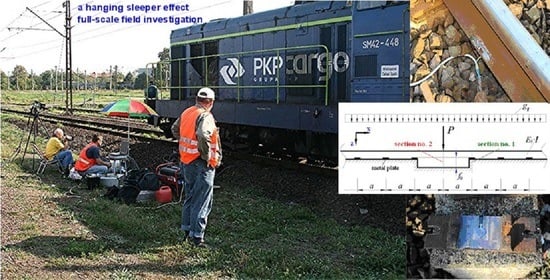
  • In the paper the author’s method, combining field research, measurements and simulation of an unfavorable phenomenon in the track (the effect of a hanging sleeper) and a computational analysis using the field research carried out, is presented.
  • The simulated short irregularity in the railway track (Figure 3) causes a significant change in the work of its individual elements. On the basis of the performed investigations and analyses, experimental relationships are obtained to describe the changes in the values of deflections and stresses (in the rail and sleeper). Such relationships can be utilized for the engineering interpretations and applications.
  • The influence of this irregularity (visible after the load is applied) was experimentally analyzed in the paper. It was observed that the induced irregularity, with an irregularity gap f0 in the track, significantly changes the work of the loaded elements of the railway track structure (increase in rail deflections was up to approximately 77% and the sleeper to 99%). A similar form of deformation in the track (vertical irregularities) arises during its operation.
  • For the case of a track deformation caused by a non-homogeneous foundation of the sleepers, the author created the intended irregularity with the given initial values of the wavelength of irregularity and its gap (Figure 3)—the effect of the hanging sleeper. In addition, one can conclude that:
    The influence of this irregularity is visible under the influence of the applied load (Figure 6);
    The proposed method of generating irregularity in the railway track (by placing non-deformable distance plates on the railway track and placing measuring sensors in the rail pad) allows the creation of the intended form with known initial values of length l0, and, above all, the desired irregularity gap f0 (Figure 3);
    It is a non-destructive method of causing irregularity, which does not damage the original contact between the rail and the sleeper with the foundation.
  • The presented methods are particularly useful in examining changes in track support and may be appropriate tools for assessing the work of loaded track elements during operation.

Funding

This research received no external funding.

Institutional Review Board Statement

Not applicable.

Informed Consent Statement

Not applicable.

Data Availability Statement

Accepted and complied with.

Acknowledgments

The author would like to thank the PKP Polish Railway Lines Poznan-Franowo for helping during the experimental setup and the site surveys. The research was financially supported by the Statutory Activity 0413/SBAD/5445, Poznan University of Technology, Faculty of Civil and Transport Engineering, lnstitute of Civil Engineering, Division of Bridges and Railway Engineering, 5 Piotrowo Street, 60-965 Poznan, Poland.

Conflicts of Interest

The author declares no conflict of interest.

References

  1. Abadi, T.; Le Pen, L.; Zervos, A.; Powrie, W. Improving the performance of railway tracks through ballast interventions. Proc. Inst. Mech. Eng. Part F J. Rail Rapid Transit 2018, 232, 337–355. [Google Scholar] [CrossRef]
  2. Sol-Sánchez, M.; Moreno-Navarro, F.; Rubio-Gámez, M.C. The use of elastic elements in railway tracks: A state of the art review. Constr. Build. Mater. 2015, 75, 293–305. [Google Scholar] [CrossRef]
  3. Abu Sayeed, M.; Shahin, M.A. Three-dimensional numerical modelling of ballasted railway track foundations for high-speed trains with special reference to critical speed. Transp. Geotech. 2016, 6, 55–65. [Google Scholar] [CrossRef] [Green Version]
  4. Liu, G.; Li, P.; Wang, P.; Liu, J.; Xiao, J.; Chen, R.; Wei, X. Study on structural health monitoring of vertical vibration of ballasted track in high-speed railway. J. Civ. Struct. Health Monit. 2021, 11, 451–463. [Google Scholar] [CrossRef]
  5. Bednarek, W.A. Analysis of static forces generated in-track on a railway sleeper resting on an elastic foundation due to structural imperfections using the PONTOS system. In Proceedings of the MATEC Web of Conferences, Krynica-Zdrój, Poland, 16–20 September 2018; EDP Sciences: Les Ulis, France, 2019; Volume 262, p. 6. [Google Scholar] [CrossRef]
  6. Milne, D.; Le Pen, L.; Watson, G.; Thompson, D.; William Powrie, W.; Hayward, M.; Morley, S. Monitoring and repair of isolated trackbed defects on a ballasted railway. Transp. Geotech. 2018, 17, 61–68. [Google Scholar] [CrossRef]
  7. Guerrieri, M.; Parla, G. A new high-efficiency procedure for aggregate gradation determination of the railway ballast by means image recognition method. Arch. Civ. Eng. 2013, LIX, 469–482. [Google Scholar] [CrossRef] [Green Version]
  8. Bednarek, W.A. Analysis of continuous welded rail track stability in vertical plane. Arch. Civ. Eng. 2006, LII, 105–125. [Google Scholar]
  9. Lim, N.-H.; Park, N.-H.; Kang, Y.-J. Stability of continuous welded rail track. Comput. Struct. 2003, 81, 2219–2236. [Google Scholar] [CrossRef]
  10. Jing, G.; Luo, Q.; Wang, Z.; Shen, Y. Micro-analysis of hanging sleeper dynamic interactions with ballast bed. J. Vibroeng. 2015, 17, 444–454. [Google Scholar]
  11. Ishida, M. The progress mechanism of track geometrical irregularity focusing on hanging sleepers. Int. J. Railw. Res. 2015, 2, 15–23. [Google Scholar]
  12. Lundqvist, A.; Dahlberg, T. Load impact on railway track due to unsupported sleepers. Proc. Inst. Mech. Eng. Part F J. Rail Rapid Transp. 2005, 219, 67–77. [Google Scholar] [CrossRef]
  13. Augustin, S.; Gudehus, G.; Huber, G.; Schüunemann, A. Numerical model and laboratory tests on settlement of ballast track. In System Dynamics and Long-Term Behaviour of Railway Vehicles, Track and Subgrade; Popp, K., Schiehlen, W., Eds.; Springer: Berlin/Heidelberg, Germany, 2003; pp. 317–336. [Google Scholar] [CrossRef]
  14. Grassie, S.L.; Cox, S.J. Dynamic response of railway track with unsupported sleepers. Proc. Inst. Mech. Eng. Part D Transp. Eng. 1985, 199, 123–135. [Google Scholar] [CrossRef]
  15. Yang, L.A.; Powrie, W.; Priest, J.A. Dynamic stress analysis of a ballasted railway track bed during train passage. J. Geotech. Geoenviron. Eng. 2009, 135, 680–689. [Google Scholar] [CrossRef]
  16. Egana, J.I.; Vinolas, J.; Seco, M. Investigation of the influence of rail pad stiffness on rail corrugation on a transit system. Wear 2006, 261, 216–224. [Google Scholar] [CrossRef]
  17. Arslan, M.A.; Kayabasi, O. 3-D Rail–Wheel contact analysis using FEA. Adv. Eng. Softw. 2012, 45, 325–331. [Google Scholar] [CrossRef]
  18. Karttunen, K. Influence of Rail, Wheel and Track Geometries on Wheel and Rail Degradation; Chalmers University of Technology: Göteborg, Sweden, 2015; ISBN 978-91-7597-203-9. ISSN 0346-718X. [Google Scholar]
  19. Larsson, D. A Study of the Track Degradation Process Related to Changes in Railway Traffic; Luleå University of Technology: Porsön, Sweden, 2004. [Google Scholar]
  20. Pombo, J.; Ambrósio, J.; Rereira, M.; Verardi, R.; Ariaudo, C.; Kuka, N. Influence of track conditions and wheel wear state on the loads imposed on the infrastructure by railway vehicles. Comput. Struct. 2011, 89, 1882–1894. [Google Scholar] [CrossRef]
  21. Remennikov, A.M.; Kaewunruen, S. A review of loading conditions for railway track structures due to train and track vertical interaction. Struct. Control Health Monit. 2007, 15, 207–234. [Google Scholar] [CrossRef]
  22. Bowe, C.J.; Mullarkey, T.P. Wheel-rail contact elements incorporating irregularities. Adv. Eng. Softw. 2005, 36, 827–837. [Google Scholar] [CrossRef]
  23. Grassie, S.L. Rail corrugation: Advances in measurement, understanding and treatment. Wear 2005, 258, 1224–1234. [Google Scholar] [CrossRef]
  24. Povilaitienė, I.; Laurinavičius, A. Reduction of external rail wearing on road curves. J. Civ. Eng. Manag. 2004, X, 123–130. [Google Scholar] [CrossRef]
  25. Iwnicki, S.D.; Bevan, A.J. Damage to Railway Wheels and Rails: A Review of the Causes, Prediction Methods, Reduction and Allocation of Costs. Int. J. Railw. Technol. 2012, 1, 121–146. [Google Scholar] [CrossRef]
  26. Dong, K.; Connolly, D.P.; Laghrouche, O.; Woodward, P.K.; Alves Costa, P. The stiffening of soft soils on railway line. Transp. Geotech. 2018, 17, 178–191. [Google Scholar] [CrossRef]
  27. Paixao, A.L.M. Transition Zones in Railway Tracks. An Expiremental and Numerical Study on the Structural Behaviour. Ph.D. Thesis, Faculdade de Engenharia Universidade do Porto (FEUP), Porto, Portugal, 2014. [Google Scholar]
  28. Varandas, J.N.; Hölscher, P.; Silva Manuel, A.G. Dynamic behaviour of railway tracks on transitions zones. Comput. Struct. 2011, 89, 1468–1479. [Google Scholar] [CrossRef]
  29. Dai, G.; Su, M. Full-scale field experimental investigation on the interfacial shear capacity of continuous slab track structure. Arch. Civ. Mech. Eng. 2016, 16, 485–493. [Google Scholar] [CrossRef]
  30. Kraśkiewicz, C.; Zbiciak, A.; Oleksiewicz, W.; Karwowski, W. Static and dynamic parameters of railway tracks retrofitted with under sleeper pads. Arch. Civ. Eng. 2018, LXIV, 187–201. [Google Scholar] [CrossRef] [Green Version]
  31. Liu, Y.M.; Yang, T.Y.; He, Z.; Li, J.Y. Analytical modeling of grinding process in rail profile correction considering grinding pattern. Arch. Civ. Mech. Eng. 2018, 18, 669–678. [Google Scholar] [CrossRef]
  32. Zaker, J.A.; Xia, H.; Fan, J.J. Dynamic response of train-track system to single rail irregularity. Lat. Am. J. Solids Struct. 2009, 6, 89–104. [Google Scholar]
  33. Available online: https://www.gom.com/en/products/high-precision-3d-metrology/pontos-live (accessed on 22 June 2021).
  34. Akas, A.Y.; Aksoydan, M. Transfer and stiffness matrix for Timoshenko beams on elastic foundations. ARI Bull. Istanb. Tech. Univ. 2004, 54, 1–15. [Google Scholar]
  35. Al-Azzawi, A.A.; Shaker, A.S. Finite difference analysis of curved deep beams on Winkler foundation. ARPN J. Eng. Appl. Sci. 2011, 6, 42–48. [Google Scholar]
  36. Dudzik, A.; Obara, P. Analiza Stateczności Belki Timoshenki Spoczywającej na Podłożu Sprężystym. Acta Sci. Pol. Archit. 2010, 9, 17–29. Available online: www.architectura.actapol.net/tom9/zeszyt1 (accessed on 26 April 2021).
  37. Kerr, A.D. On the vertical modulus in the standard railway track analyses. Rail Int. 1987, 11, 37–45. [Google Scholar]
  38. Vallabhan, C.V.G.; Das, Y.C. Parametric study of beams on elastic foundations. J. Eng. Mech. Div. 1988, 114, 2072–2082. [Google Scholar] [CrossRef]
  39. Eisenberger, M.; Bielak, J. Finite beams on infinite two-parameter elastic foundations. Comput. Struct. 1992, 42, 661–664. [Google Scholar] [CrossRef]
  40. Teodoru, I.-B.; Muşat, V. Beam Elements on Linear Variable Two-Parameter Elastic Foundation. Bul. Inst. Politeh. Din Iaşi Tomul. 2008, LIV(LVIII), 69–78. Available online: www.bipcons.ce.tuiasi.ro/Content/ArticleInformation.php?ArticleID=118 (accessed on 26 April 2021).
  41. Vlasov, V.Z.; Leont’ev, N.N. Beams, Plates, and Shells on Elastic Foundation; Israel Program for Scientific Translations: Jerusalem, Israel, 1966; pp. 1–94, (Translated from Russian). [Google Scholar]
  42. Teodoru, I.-B.; Muşat, V. The modified Vlasov foundation model: An attractive approach for beams resting on elastic supports. Electron. J. Geotech. Eng. 2010, 15, 1–13. Available online: www.ejge.com/2010/JourTOC15C.htm (accessed on 26 April 2021).
  43. Vallabhan, C.V.G.; Das, Y.C. Modified Vlasov model for beams on elastic foundations. J. Geotech. Eng. 1991, 117, 956–966. [Google Scholar] [CrossRef]
  44. Bednarek, W.A. Determination of foundation coefficients for a 2-parameter model on the basis of railway sleeper deflection. In Continuous Media with Microstructure 2; Springer International Publishing: Cham, Switzerland, 2016; pp. 325–341. ISBN 978-3-319-28239-8. [Google Scholar] [CrossRef]
  45. Eisenberger, M.; Yankelevsky, D.Z. Exact stiffness matrix for beams on elastic foundation. Comput. Struct. 1985, 21, 1355–1359. [Google Scholar] [CrossRef]
  46. Buczkowski, W. A solving of beams at variable stiffness by finite differences method. Architectura 2009, 8, 49–64. (In Polish) [Google Scholar]
Figure 1. Typical examples of imperfections arising in a railway track: (a) an irregularity (in consequence of a change in sleeper types); (b) variable support of the track structure along the railway track; (c) a rail corrugation [16]; (d) triple irregularities in the track (an example).
Energies 14 07477 g001
Figure 2. The under sleeper pads with fully covered bottom surface and partially covered bottom surface of the railway sleeper (under rail section) [2,30].
Energies 14 07477 g002
Figure 9. The rail stresses caused by induced irregularity in the railway track (the rides of locomotive’s succeeding axles): (a) measured by an extensometer in cross-section no. 2 (Figure 3); (b) measured by an extensometer in cross-section no. 1 (Figure 3).
Energies 14 07477 g009
Figure 11. The force transferred from the rail to the sleeper due to the induced irregularity in the railway track for the scheme from Figure 3 (the loads from the locomotive’s succeeding axles): (a) a measurement by a force sensor in cross-section no. 2 (a record on the force sensor); (b) a measurement by a force sensor in cross-section no. 1.
Energies 14 07477 g011aEnergies 14 07477 g011b
Figure 12. A dependence on the force transferred from the rail to the railway sleeper on the f0 value of irregularity induced in the railway track (the loads from the locomotive’s succeeding axles; the scheme from Figure 3—the site surveys): (a) the change of the force in section no. 2 from a force in section no. 2 (the succeeding axles); (b) the change of the force in section no. 1 from a force in section no. 2 (the succeeding axles); (c) the change of the force in section no. 1 from a force in section no. 1 (the succeeding axles); (d) the change of the force in section no. 2 from a force in section no. 1 (the succeeding axles).
Energies 14 07477 g012aEnergies 14 07477 g012b
Figure 13. Exemplary assumed simplified schemes for an analysis of a generated irregularity in track deflection for the considered section no. 2 of the track (Figure 3).
Energies 14 07477 g013
Figure 14. The railway sleeper assumed for a theoretical analysis (INBK-7 type).
Energies 14 07477 g014
Table 2. The assumed additional parameters for calculations.
The Rail 49E1 of the Analyzed Railway Track Is Divided into Elements:The Following Data is Used for the Railway Sleeper, Treated as a Timoshenko’s Beam:
  • Contacting with the foundation at a length l = 0.1625 [m],
  • Without contact with the foundation at a length l = 0.05 [m],
  • ES = 210 [GPa] and I49E1 = 1819 [cm4].
  • The element’s stiffness is calculated as a harmonic mean from the Formula (5.1) [46],
  • G = E b 2 × ( 1 + v ) = 0.43 × E b .   It   is   assumed   that :   ν = 1 6   and   E b = 35   [ G P a ] [5], κ = 1.2 ,   ζ = κ × E s × I G × A e l ,
  • A concrete sleeper compressed by force: S = 0309 [MN].
where: G—Kirchhoff’s module [GPa]; κ—shape coefficient of the cross-section; Ael—cross-sectional area of the element; G·Ael—shear beam stiffness.
Publisher’s Note: MDPI stays neutral with regard to jurisdictional claims in published maps and institutional affiliations.

