1. Introduction
The photoelectrochemical (PEC) water splitting system has been considered a promising pathway for generating eco-friendly hydrogen [
1,
2,
3]. In the PEC water splitting system, semiconductor photoelectrodes play a significant role because they produce electron-hole pairs by absorbing the sunlight, inducing water splitting reactions in the interface between the photoelectrode and water [
4,
5,
6]. The PEC performance of photoelectrodes is important for efficient hydrogen generation because it determines the solar-to-hydrogen (STH) efficiency of a PEC water splitting system. In addition, the stability of photoelectrodes is significant for sustainable hydrogen production due to the feasibility of the degradation in the water, resulting in the loss of PEC performances. Therefore, the development of efficient and durable photoelectrodes with low-cost materials is essential for a practical PEC water splitting system.
Cuprous oxide (Cu
2O) is a promising candidate material for efficient and durable photoelectrodes due to its band position, optical characteristic, non-toxicity, and abundancy [
7,
8,
9]. It is suitable for a PEC photocathode because it is a p-type semiconductor and its conduction band is more negative than the hydrogen evolution reaction (HER) potential. In addition, it has a band gap of 2 eV, facilitating the utilization of visible light up to a wavelength of 600 nm. Hence, the photocurrent density can be theoretically achieved up to −14.7 mA cm
−2 using Cu
2O as a PEC photoelectrode. It corresponds to a STH efficiency of 18%, which is higher than the standard one (10%) for the commercialization of a PEC water splitting system [
3,
10]. Although it is not stable in the water, it is avoidable by adopting the protection layer with the intrinsic stable materials [
11,
12]. The state-of-the-art Cu
2O photocathode based on a nanowire structure with a gallium oxide overlayer, titanium oxide (TiO
2) protection layer, and ruthenium oxide (RuO
x) HER catalysts shows a photocurrent density of −10 mA cm
−2 at HER potential and stability over 100 h [
13]. It is a considerable PEC performance with remarkable stability, however, it is limited to the lab scale Cu
2O photocathode below 1 cm
2.
Upscaling of photoelectrodes is inevitable for a practical PEC water splitting system because it facilitates the mass production of hydrogen. Nevertheless, the quite low PEC performance in a large-scale photoelectrode compared to the lab scale photoelectrode has remained an unsolved problem. It is mainly caused by the potential drop from the ohmic loss in a large-scale substrate [
14,
15,
16,
17]. To overcome this problem in the large-scale photoelectrode, few efforts on reducing the substrate ohmic loss have been reported. W.J. Lee et al. developed a large area, tungsten oxide photoanode-inserted silver (Ag) grid with an area of 130 cm
2 [
18]. It was demonstrated that the screen-printed Ag grid is effective in improving the conductivity of large area photoelectrodes. I.Y. Ahmet et al. introduced the electrodeposited nickel line to reduce the potential drop in the large scale (50 cm
2) bismuth vanadate photoanode [
19]. A. Vilanova et al. reported a 200-cm
2 PEC-photovolatic (PV) water splitting device based on the hematite (Fe
2O
3) photoanode [
20]. They fabricated the modular large scale Fe
2O
3 photoanode assembled with several pieces of small Fe
2O
3 photoanode, reducing the ohmic loss in a large scale photoelectrode. X. Xiao et al. developed a 60-cm
2 tantalum nitride photoanode on the metal titanium substrate, which has better conductivity compared to the transparent conductive substrate [
21]. However, to the best of our knowledge, the study on the reduction of ohmic loss in large-scale Cu
2O photocathode has still not been reported elsewhere, despite the Cu
2O photocathode being in the limelight for its efficient and durable PEC water splitting system.
In this work, a large-scale Cu2O photocathode with a metal grid structure was designed for reducing the ohmic loss of a large area of Cu2O photocathodes. The electrodeposited Cu2O photocathodes consisting of an aluminum doped zinc oxide (AZO) overlayer, TiO2 protection layer, and RuOx HER catalysts were prepared on the metal grid sputtered large-scale fluorine-doped tin oxide (FTO) substrate. Gold (Au) and copper (Cu) metal grid lines were introduced to reduce the ohmic loss in the large substrate and their effects on the PEC performance of large area Cu2O photocathode were analyzed. Finally, the Cu grid-embedded large scale Cu2O photocathode was tested in outdoor conditions under natural sun. It is the first outdoor demonstration of a PEC water splitting operation using large scale Cu2O photocathode with a metal grid structure. Therefore, it would be a worthwhile footprint for practical PEC water splitting using Cu2O photocathodes and it would provide valuable insights on the upscaling of PEC photoelectrodes toward the commercialization of a PEC water splitting system.
2. Materials and Methods
Prior to the fabrication of Cu
2O photocathode, the FTO coated glass substrate (TEC-15, G2E) was cleaned by successive ultrasonication processes for 10 min in acetone, ethanol, and distilled water, respectively. The substrate cleaning was completed by ultraviolet/ozone plasma treatment for 10 min to remove remained residues. Before the Cu
2O deposition, metal grid lines (Au or Cu grid lines) were sputtered on a cleaned FTO substrate by using the sputtering deposition system (DP-650, Alliance-Concept, Annecy, France) at room temperature. The thickness of the metal grid was fixed at 150 nm by adjusting the deposition time based on the deposition ratio of each metal. The dimension of metal grid lines with a width of 10 mm, a gap between each grid line of 50 mm was determined by the mask with Kapton tape. A sputtered chromium (Cr) interlayer with a thickness of 45 nm was inserted between the FTO substrate and the metal grid to improve the adhesion of metal grid onto the FTO substrate [
22].
Large scale Cu
2O photocathode was fabricated on the prepared FTO substrates with and without metal grid lines, following the fabrication process as reported previously [
23,
24,
25]. In brief, the Cu
2O films were deposited by the electrodeposition. A 3-nm thin Au film was sputtered for better Cu
2O deposition and hole extraction, before electrodeposition. The constant current density of −0.1 mA cm
−2 was applied in a lactate-stabilized copper sulfate aqueous solution (pH 12) with a platinum (Pt) mesh counter electrode during the Cu
2O electrodeposition. It was carried out for 50 min, which was a deposition time for the optimal PEC performance of electrodeposited Cu
2O photocathodes [
25]. A 20-nm thick AZO overlayer was deposited on the Cu
2O film to make a p-n junction for better charge separation. Sequentially, a 100-nm thick TiO
2 layer was deposited to protect the Cu
2O film. Both films were deposited by a thermal atomic layer deposition (Savannah 100, Cambridge Nanotech, Cambridge, USA). RuO
x HER catalysts were finally deposited by photodeposition, applying a constant current density of −28.3 μA cm
−2 for 15 min in a 1.3-mM potassium perruthenate (KRuO
4) solution under light illumination. After that, Ag contacts were deposited on edges of the FTO substrate for the efficient charge collection to the external connection. In detail, Ag paint (ElectroDAG 1415, Agar Scientific, Essex, UK) was brushed on the edges of the FTO substrate, and was dried at 80 °C for 30 min. The area of the large scale Cu
2O photocathodes was determined by masking epoxy (Loctite Hysol, Düsseldorf, Germany) as 25 cm
2 for the study on the grid effect and 50 cm
2 for the outdoor test, respectively.
Electrochemical characterizations were carried out using a standard three-electrode system with a working electrode, Pt mesh counter electrode, and silver/silver chloride (Ag/AgCl) reference electrode in the saturated potassium chloride. Measured data were obtained by a potentiostat (SP-200, Bio-Logic Science Instrument, Seyssinet-Pariset, France). The potential versus Ag/AgCl reference electrode was converted into a reverse hydrogen electrode (RHE) scale using the equation: VRHE = VAg/AgCl + 0.197 V + 0.059 V pH. The PEC performance of a large scale Cu2O photocathode was measured in a pH 5 aqueous solution consisting of 0.1 M of potassium phosphate monobasic (KH2PO4) and 0.5 M of sodium sulfate (Na2SO4) under light illumination with a scan rate of 10 mV s−1 and a scan direction from positive to negative potential. Chronoamperometry (CA) measurement was carried out at the HER potential (0 V versus RHE) under continuous light illumination for the stability test. The light source for the measurement of a 25 cm2 scaled Cu2O photocathode was a 100-W ozone free Xenon lamp equipped with an air mass (AM) 1.5 G filter (Oriel LCS-100, Newport, Irvine, USA). The light intensity was one sun illumination (100 mW cm−2) calibrated by a silicon diode. On the other hand, the light source for the measurement of a 50-cm2 scaled Cu2O photocathode was a home-made warm white LED array due to the limitation of lamp size. The light intensity was calibrated to the similar intensity of one sun illumination based on the current information from a silicon diode. Natural sun was a light source for the outdoor PEC operation, and its intensity was calculated using a silicon diode.
To evaluate the grid effect on the PEC performance, the partial PEC performance of large scale Cu2O photocathode was measured. For this measurement, a 25-cm2 scaled Cu2O photocathode with and without metal grid lines was divided into three parts (upper, middle, and bottom) with an area of 8.3 cm2 using a mask. In addition, the sheet resistance values of Cu2O photocathode with and without metal grid lines were compared by a 4-probe measurement system (Kiethley 2400, Tektronix, Beaverton, OR, USA). Morphology of a large scale Cu2O photocathode with metal grid lines was analyzed by a high-resolution scanning electron microscope (SEM, Zeiss Merlin, Oberkochen, Germany).
3. Results and Discussion
Figure 1 shows the PEC performance of small-scale (0.25 cm
2) and large-scale (25 cm
2) Cu
2O photocathodes with an AZO overlayer, TiO
2 protection layer, and RuO
x HER catalysts in a pH 5 aqueous solution under chopped one sun illumination. As shown in
Figure 1, the onset potential was approximately 0.5 V versus RHE and the photocurrent density reached up to −5.1 mA cm
−2 at HER potential (0 V versus RHE) in the small-scale Cu
2O photocathode. It is in good agreement with the previous report [
25]. On the other hand, the photocurrent density at HER potential was reduced to −1.5 mA cm
−2, while the onset potential was not changed in the large-scale Cu
2O photocathode. Interestingly, although the composition of Cu
2O photocathode was same, the photocurrent density was remarkably decreased when the area of photocathode was increased a hundred-fold. A large area substrate can affect the uniformity of the Cu
2O film or the charge transport in the Cu
2O photocathode. It influences the PEC performance of the Cu
2O photocathode, especially the photocurrent density. Non-homogeneous Cu
2O film plays a role as a recombination center, resulting in poor PEC performance [
24]. However, it was demonstrated that the electrodeposited Cu
2O film is quite homogenous even on the 50-cm
2 scaled large FTO substrate, with an approximate thickness of 280~300 nm (
Figure S1). Hence, the non-uniformity of Cu
2O film can be excluded from the reason for the decreased PEC performance in the large-scale Cu
2O photocathode. Therefore, the poor PEC performance of the large-scale Cu
2O photocathode is likely due to the ohmic loss by the prolonged charge transport in the large area substrate [
14,
15,
16,
17].
Metal grid lines were introduced to overcome this problem in the large-scale Cu
2O photocathode because they are a mature strategy for improving the charge transport in the large-scale dye-sensitized solar cells and perovskite solar cells [
26,
27,
28,
29].
Table 1 shows the reported conductivity of metals, which were considered as metal grid lines [
30,
31]. Ag was preferentially considered due to its high conductivity. However, most Ag grid lines peeled off during the electrodeposition of Cu
2O. Hence, Cu and Au were alternatively selected because they also have better conductivity compared to other metals, even though they are less conductive than Ag.
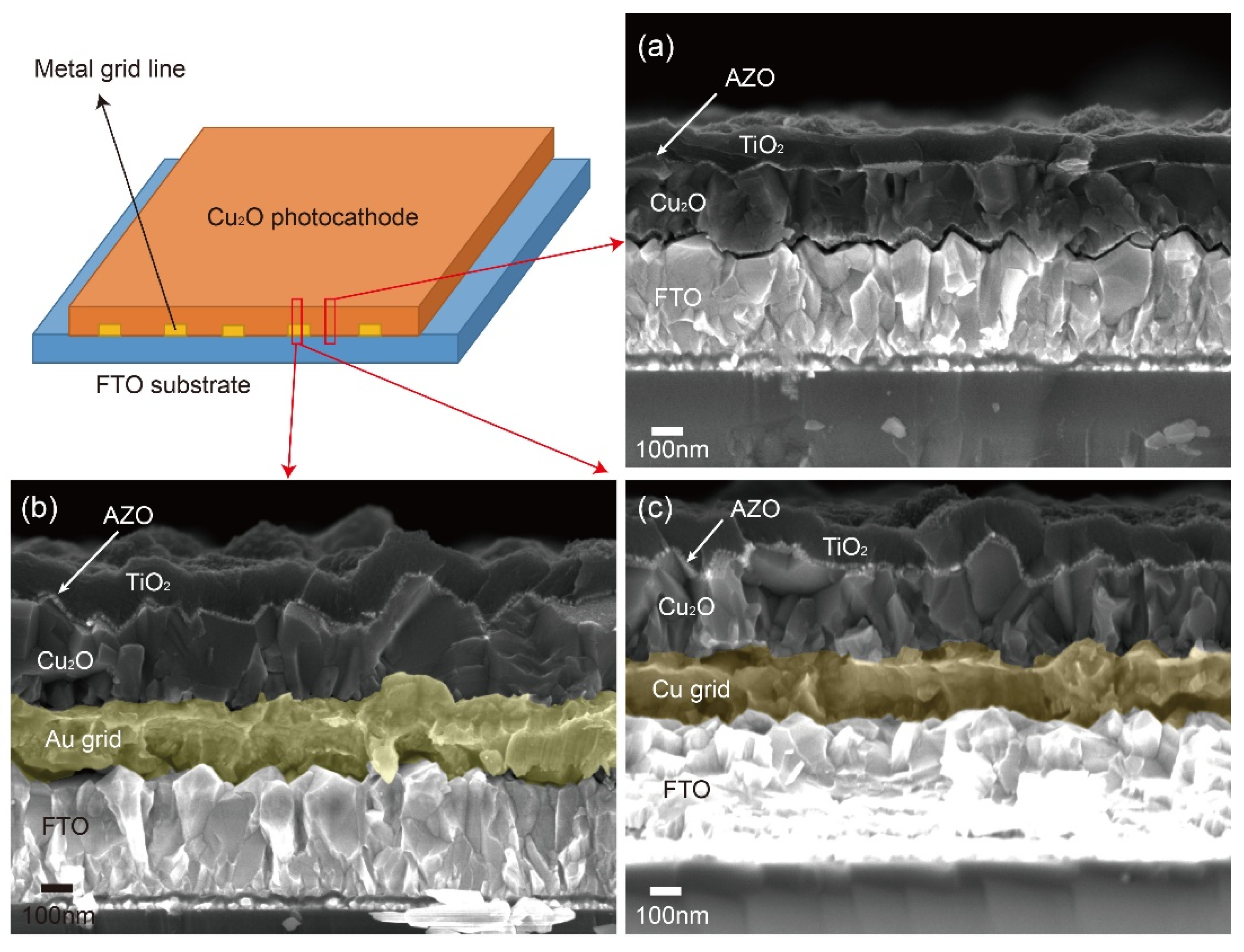
Figure 2 shows the schematic designs and photographs of 25-cm
2 scaled Cu
2O photocathodes with sputtered Au and Cu grid lines. Metal grid lines did not hinder the light absorption to the large scale Cu
2O photocathode because the Cu
2O film was electrodeposited on the metal grid lines (
Figure 2a) and the light was illuminated to the Cu
2O film side, not the FTO substrate side. It seems that the quality of Cu grid lines (
Figure 2c) was better than one of Au grid lines (
Figure 2b) in the large scale Cu
2O photocathode. Nevertheless, both thicknesses were almost the same at approximately 160 nm and their contacts with Cu
2O film were dense and well connected, as shown in
Figure 3b,c. In addition, the thicknesses of the Cu
2O film (260 nm), AZO overlayer (20 nm), and TiO
2 protection layer (100 nm) were almost the same in the part without the grid line (
Figure 3a), with the Au grid line (
Figure 3b), and Cu grid line (
Figure 3c), respectively. It means that all layers of the Cu
2O photocathode were homogenously deposited on the grid-embedded large scale substrate.
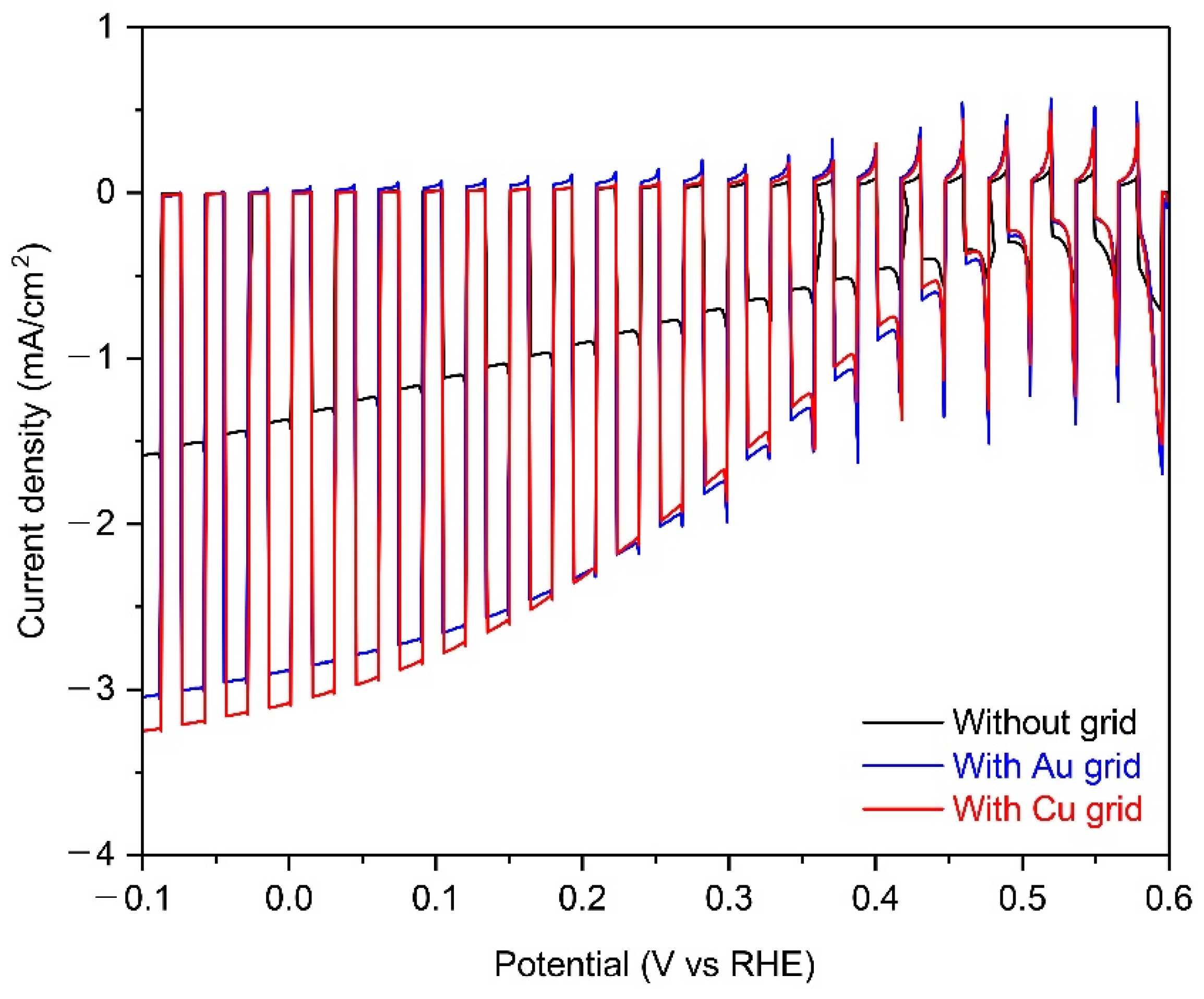
Figure 4 shows the PEC performance of 25-cm
2 scaled Cu
2O photocathodes without grid lines and with Au or Cu grid lines in a pH 5 aqueous solution under chopped one sun illumination. The photocurrent density at 0 V versus RHE of Cu
2O photocathode with metal grid lines were almost double than one of the Cu
2O photocathode without metal grid lines, while the onset potential was the same. It is likely due to the improved chare transport by the metal grid lines because other conditions of the Cu
2O photocathode were the same, as mentioned in
Figure 3. On the other hand, the improvement of photocurrent density in the Cu grid-embedded Cu
2O photocathode was slightly higher than one in the Au grid-embedded Cu
2O photocathode. It is mainly caused by the different charge transport capabilities of the two metals. Herein, the charge transport capability is affected by the inherent conductivity of metals because the width, length, and thickness of each grid lines are the same [
27]. As shown in
Table 1, the conductivity of Cu (5.96 × 10
7 S m
−1) is superior to one of Au (4.11 × 10
7 S m
−1), resulting in the further improved PEC performance using Cu grid lines. In addition, the quality of the Cu grid was better than the Au grid (
Figure 2b,c). Therefore, it was concluded that the Cu grid is more effective in improving the charge transport in the large-scale Cu
2O photocathode, compared to the Au grid.
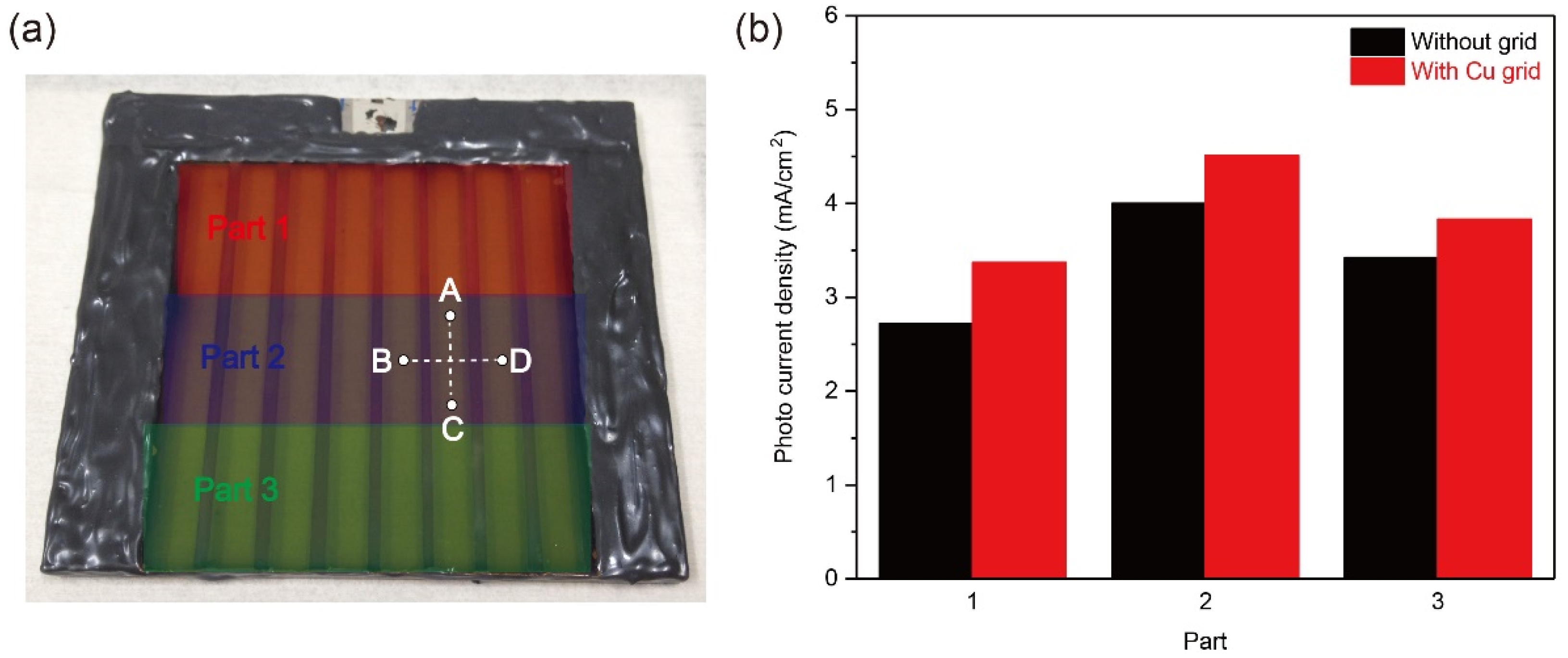
To evaluate the Cu grid effect on the large-scale Cu
2O photocathode, the partial PEC performance and the sheet resistance value of large-scale Cu
2O photocathodes without and with Cu grid lines were analyzed. Three parts with an active area of 8.3 cm
2 were divided for the partial PEC performance measurement, as illustrated in
Figure 5a (Part 1, 2, and 3). The measured area was exposed to light illumination, while other parts were covered by the mask during the PEC measurement.
Figure 5b shows the photocurrent densities of each part without and with Cu grid lines at 0 V versus RHE in a pH 5 aqueous solution under one sun illumination. All photocurrent densities were improved after introducing Cu grid lines, compared to the Cu
2O photocathode without Cu grid lines. It intuitively supports that the charge transport of all parts was improved by the Cu grid lines. On the other hand, the sheet resistance of the Cu
2O photocathode without and with Cu grid lines was measured. The charge flow was controlled in two directions, as shown in
Figure 5a: One direction is parallel to the grid lines (C → A) and the other direction is perpendicular to the grid lines (B → D). As shown in
Table 2, resistance values measured from two charge flow directions were reduced by introducing Cu grid lines. In particular, when the Cu grid lines were applied to the Cu
2O photocathode, the resistance value on the charge flow from C to A was largely reduced by approximately 86.2% (3.6 Ω → 0.5 Ω), while the resistance value on the charge flow from B to D was reduced by only 25% (3.6 Ω → 2.7 Ω). It is strong evidence on the improvement of charge transport to the electrical connector by the Cu grid lines. Hence, it was demonstrated that the Cu grid lines are effective to reduce the ohmic loss of large scale Cu
2O photocathode, leading to the improved PEC performance.
For the demonstration of a large-scale Cu
2O photocathode in an outdoor condition, a 50-cm
2 scaled Cu
2O photocathode with Cu metal grid lines were fabricated. Although the size of electrode was doubled, all compositions of Cu
2O photocathode were homogenously deposited on the substrate and the quality of Cu grid lines was good, as shown in
Figure S2. In addition, the sample was quite transparent (
Figure S2), which is suitable for the tandem water splitting system with a large-scale PEC photoanode or a PV module as a bottom absorber. However, in this case, the design of Cu grid lines should be optimized because grid lines restrict the light absorption to the bottom absorber.
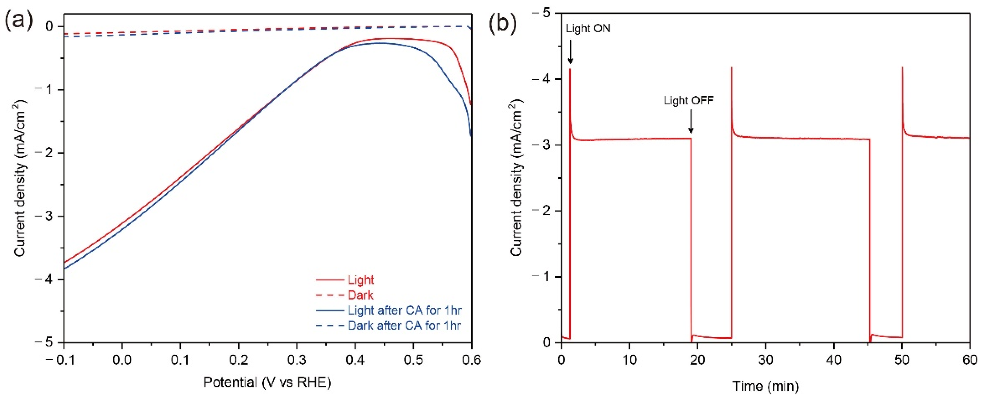
Figure 6 shows the PEC performance and stability of the Cu grid-embedded 50-cm
2 Cu
2O photocathode in a pH 5 aqueous solution under the continuous light from the warm white LED array with the similar intensity of one sun illumination before the outfield demonstration. The light from warm white LED array covers the visible light (
Figure S3), thus it is suitable for the PEC measurement of large-scale Cu
2O photocathodes. As shown in
Figure 6a, the photocurrent density reached up to −3.1 mA cm
−2, which was similar with one of the 25-cm
2 scaled Cu
2O photocathode with Cu grid lines. Moreover, it was maintained without any decreases during the PEC operation for 60 min (
Figure 6b). After the stability test, the PEC performance of a 50-cm
2 Cu
2O photocathode with Cu grid lines was remeasured to indirectly evaluate its stability. Surprisingly, it showed a similar PEC performance with the unchanged small dark current. It guarantees that there were no degradations on the Cu grid-embedded large-scale Cu
2O photocathode during the continuous PEC operation. In other words, the Cu grid line does not affect the stability of the large-scale Cu
2O photocathode.
The outdoor PEC operational demonstration of a 50-cm
2 Cu
2O photocathode with Cu grid lines was carried out in the late afternoon of autumn. The intensity of sunlight was 0.57 sun, which was calculated using the measured current density from the silicon diode. The container for the PEC demonstration was provided and designed by the University of Porto [
32].
Figure 7 shows the PEC performance of the Cu grid-embedded 50-cm
2 Cu
2O photocathode in a pH 5 aqueous solution under natural sun. The photocurrent density of reached up to −1.91 mA cm
−2 at 0 V versus RHE, while the onset potential was approximately 0.6 V versus RHE. It was observed that bubbles continuously came out from the surface of the Cu
2O photocathode during the continuous PEC operation at 0 V versus RHE (Movie S1). It means that the water splitting reaction occurred at the surface of the Cu grid-embedded large-scale Cu
2O photocathode. Although the gas chromatography measurement was not carried out due to the difficulty of its set up outside, it would be a significant cornerstone for the efforts on the upscaling of Cu
2O photocathodes.


