Article

CFD Simulation of Hydrogen Generation and Methane Combustion Inside a Water Splitting Membrane Reactor

1
Department of Thermal Science and Energy Engineering, University of Science and Technology of China, Hefei 230027, China
2
Collaborative Innovation Center of Chemistry for Energy Materials, Laboratory of Materials for Energy Conversion, Department of Materials Science and Engineering, University of Science and Technology of China, Hefei 230026, China
*
Author to whom correspondence should be addressed.
Energies 2021, 14(21), 7175; https://doi.org/10.3390/en14217175
Submission received: 20 September 2021 / Revised: 18 October 2021 / Accepted: 27 October 2021 / Published: 1 November 2021
(This article belongs to the Topic Hydrogen Energy Technologies)

Abstract

:
Hydrogen production from water splitting remains difficult due to the low equilibrium constant (e.g., Kp ≈ 2 × 10⁻⁸ at 900 °C). The coupling of methane combustion with water splitting in an oxygen transport membrane reactor can shift the water splitting equilibrium toward dissociation by instantaneously removing O2 from the product, enabling the continuous process of water splitting and continuous generation of hydrogen, and the heat required for water splitting can be largely compensated for by methane combustion. In this work, a CFD simulation model for the coupled membrane reactor was developed and validated. The effects of the sweep gas flow rate, methane content and inlet temperature on the reactor performance were investigated. It was found that coupling of methane combustion with water splitting could significantly improve the hydrogen generation capacity of the membrane reactor. Under certain conditions, the average hydrogen yield with methane combustion could increase threefold compared to methods that used no coupling of combustion. The methane conversion decreases while the hydrogen yield increases with the increase in sweep gas flow rate or methane content. Excessive methane is required to ensure the hydrogen yield of the reactor. Increasing the inlet temperature can increase the membrane temperature, methane conversion, oxygen permeation rate and hydrogen yield.

1. Introduction

As a clean, highly efficient and sustainable energy carrier, hydrogen is considered one of the most promising forms of alternative energy to conventional fossil fuels [1,2]. Under the increasingly severe situation of energy and environmental issues, the development of affordable, clean, and efficient hydrogen production technology is particularly important for hydrogen utilization [3]. Currently, hydrogen production methods can be broadly classified into three major categories based on the nature of their chemical processes and/or energy inputs: thermochemical, electrochemical, and biological methods [4]. Among these, thermochemical water splitting has attracted considerable attention because water is considered an ideal source due to its clean, abundant, and renewable characteristics [1,5]. However, the water splitting reaction for hydrogen generation is a thermodynamically limited reaction. The efficient hydrogen production from water ( 2 H 2 O     H 2 + O 2 ) remains difficult due to the low equilibrium constant, e.g., Kp ≈ 2 × 10⁻⁸ at 900 °C, and only low equilibrium concentrations of PO2 = 4.6 × 10⁻⁶ bar and PH2 = 9.2 × 10⁻⁶ bar are achieved [6]. Even at high temperatures, only a small amount of hydrogen can be obtained, e.g., the generated hydrogen concentration is only 0.1% at 1600 °C.
Recently, a technique of the oxygen transport membrane (OTM) reactor was developed for hydrogen production via water splitting. The OTMs are made of mixed ionic and electronic conducting materials that can simultaneously conduct electrons and oxygen ions. Thus, the membrane has a 100% selectivity to oxygen while it is impermeable to other gases; only oxygen can permeate through the membrane [7]. In a water splitting membrane reactor, one side of the membrane (defined as the feed side) is exposed to the water vapor, where water splits into oxygen and hydrogen at an elevated temperature. Inert gases (such as N2, He or Ar) or reactive gases (such as reducing gases: CO, syngas, or CH4) are introduced into the other side (defined as the sweep side) to take away or react with the permeated oxygen to form a low oxygen partial pressure on this side. Driven by the oxygen partial pressure difference between the two sides, oxygen can continuously transport from the feed side to the sweep side. Through the instantaneous removal of water decomposition products O2, the equilibrium of the water splitting reaction will be broken and shifted toward the decomposition into oxygen and hydrogen. Then, the continuous production of a substantial quantity of hydrogen can be achieved [2]. It is feasible to use the OTM reactor for water splitting to produce hydrogen. Park et al. [8] reported an experiment of using an OTM reactor based on the La0.7Sr0.3Cu0.2Fe0.8O3-δ (LSCuF−7328) membrane for hydrogen generation with water vapor fed into the feed side and coal gas (CO/CO2) fed into the sweep side. The coal gas consumed the permeated oxygen, thus improving the oxygen permeation rate and hydrogen generation (e.g., a hydrogen yield of 4.7 cm3/min·cm2 at 900 °C could be achieved). Zhu et al. [1] systematically investigated the behavior of water splitting in a La0.9Ca0.1FeO3-δ (LCF−91) OTM reactor under different reducing atmospheres (i.e., CO, H2/CO, and CH4). The results show that the LCF-91 membrane exhibits a favorable oxygen permeability and hydrogen production rates under reducing atmospheres (i.e., 6.17 × 10⁻⁸, 5.23 × 10⁻⁸ and 3.90 × 10⁻⁸ mol/cm2·s under CO, H2/CO and CH4, respectively). If the water splitting reaction is fast enough, then the oxygen permeation process will be the controlling step of the hydrogen production. The studies of Park et al. [8] on the La0.7Sr0.3Cu0.2Fe0.8O3-δ (LSCuF−7328) membrane reactor, Hong et al. [9] and Habib et al. [10] on the La0.1Sr0.9Co0.9Fe0.1O3-δ (LSCoF−1991) membrane reactor, Ben-Mansour et al. [11] on the Ba0.5Sr0.5Co0.8Fe0.2Ox (BSCoF−5582) membrane reactor, Jiang et al. [12] on the BaCoxFeyZr1-x-yO3-δ (BCoFZ) membrane reactor, Lee et al. [13] on La0.6Sr0.4Ti0.2Fe0.8O3-δ (LSTF−6428) membrane reactor, and Zhu et al. [1] on La0.9Ca0.1FeO3-δ (LCF−91) membrane reactor all show that, compared with inert gas, the use of reducing/reacting gas as a sweep gas can improve the oxygen permeability of the membrane reactor, thus leading to a higher hydrogen yield.
In recent years, researchers have proposed the concept of coupling water splitting with the partial oxidation of methane (POM) reaction, allowing the two reactions to proceed simultaneously in one apparatus [1,14,15,16,17,18]. The feed side is fed with water vapor while the sweep side is fed with methane. At 800–900 °C, the water splitting first occurs on the feed side; the product O2 permeates from the water splitting side to the sweep side through the OTM to provide the oxygen required for the POM reaction. A valuable advantage of this membrane reactor is that it can produce hydrogen and syngas simultaneously. In addition, POM is a slightly exothermic reaction, the heat released by the POM reaction can partially compensate for the heat required for water splitting. However, at a high temperature such as 800 °C, the enthalpy change for the water splitting is approximately +248 kJ/mol, and is only −23 kJ/mol for the POM reaction. Therefore, a large amount of heat needs to be provided to the reactor from the outside to facilitate the proceeding of water splitting. For this reason, if the methane combustion reaction is coupled with water splitting in an OTM reactor, more heat can be provided for the water splitting by the complete combustion of methane to further improve the hydrogen yield.
In this work, the La0.7Sr0.3Cu0.2Fe0.8O3-δ (LSCuF−7328), with a high oxygen permeability and appreciable stability, was selected as the membrane material, a CFD model for water splitting coupled with methane combustion in the LSCuF−7328 membrane reactor was developed and validated. The endothermic effect of the water splitting reaction was taken into account by adding an energy source term on the feed side. The contribution of this work is that the effect of the coupling of methane combustion on the water splitting reactor performance is analyzed and compared with the reactor without combustion. Furthermore, the effects of the sweep gas flow rate, the methane content and the inlet temperature on the reactor performance, such as the membrane temperature distribution, the oxygen permeation rate, the methane conversion and the hydrogen production rate were investigated.

2. Model

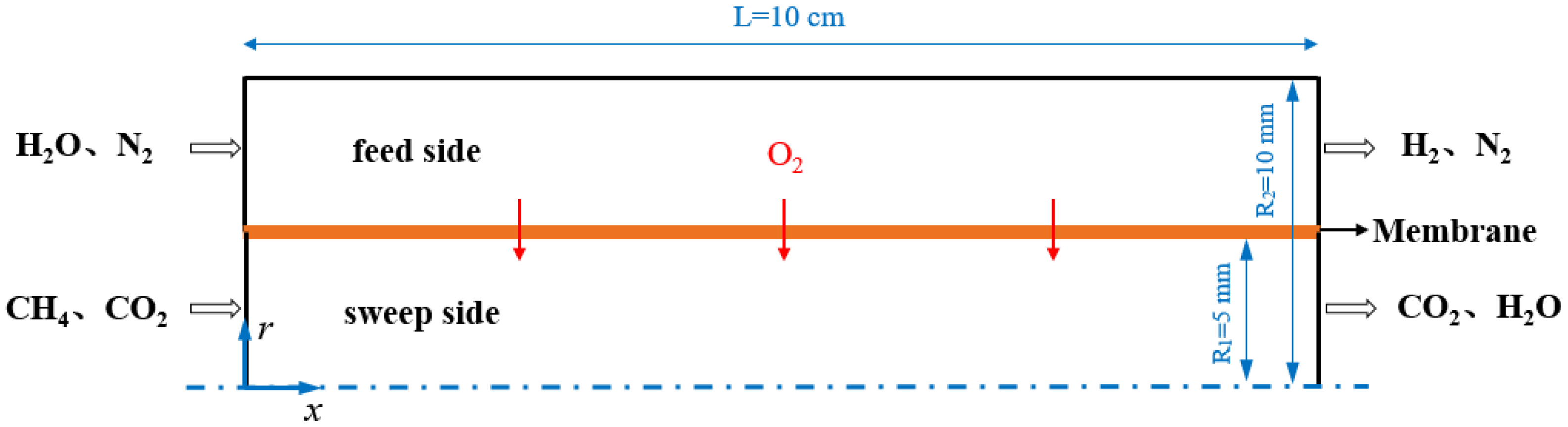
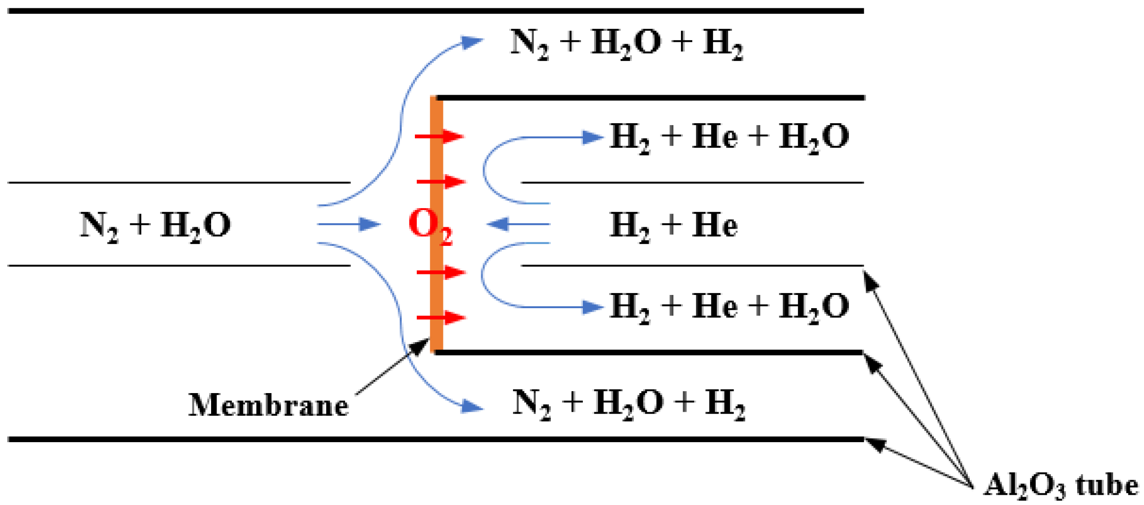
2.1. Descriptions of the Membrane Reactor

Figure 1 shows the schematic diagram of the 2D axisymmetric representation of the water splitting membrane reactor coupled with methane combustion, with x representing the axial direction and r representing the radial direction. The geometry consists of two concentric horizontal tubes with the outer tube made of quartz and the inner tube made of the LSCuF−7328 oxygen transport membrane. The reactor is divided into two zones by the membrane: a feed side and a sweep side. High-temperature water vapor in the mixture with N2 is fed into the feed side, while CH4 in mixture with CO2 as the sweep gas is introduced into the sweep side (i.e., the sweep gas is a mixture of CH4 and CO2). Both N2 and CO2 are used as the carrier gases. At an elevated temperature, oxygen and hydrogen are produced by a water splitting reaction on the feed side. Driven by the oxygen partial pressure differences across the membrane, oxygen permeates through the membrane from the feed side to the sweep side and then reacts with CH4. The permeated oxygen is consumed rapidly, the equilibrium of the water splitting reaction continues to move in the direction of generating hydrogen and oxygen, and then hydrogen is generated continuously.

2.2. Governing Equations

Due to the low velocity of the inlet gases, the flow is laminar and in a steady state at both the feed and sweep sides. The outer quartz tube of the reactor is assumed to be isothermal and impermeable. The permeation process of oxygen through the OTM is achieved by adding sink and source terms in the areas adjacent to the membrane surface [19]. That is, oxygen is allowed to disappear from the feed side through the sink term and reappear on the sweep side through the source term. The mathematic model describing the processes of the flow, heat and mass transfer, as well as reaction of the two-dimensional axisymmetric (x− and r−coordinates) reactor geometry, includes the following governing conservation equations [20]:
Continuity equation:
x ( ρ u ) + 1 r r ( r ρ v ) = S i
Momentum conservation equations:
x-momentum equation:
x ( ρ u u ) + 1 r r ( r ρ v u ) = p x + x ( μ u x ) + 1 r r ( r μ u r )
r-momentum equation:
x ( ρ u v ) + 1 r r ( r ρ v v ) = p r + x ( μ v x ) + 1 r r ( r μ v r )   μ v r 2
Energy conservation equation:
x ( ρ c p u T ) + 1 r r ( r ρ c p v T ) = x ( k T x ) + 1 r r ( r k T r ) + S h
Species balance equation:
x ( ρ u Y i ) + 1 r r ( r ρ v Y i ) = x ( ρ D i , m Y i x ) + 1 r r ( r ρ D i , m Y i r ) + S i   + R i
where u and v are the velocity components of the fluid in the x- and r-directions, respectively, p is the local pressure, T is the local temperature, ρ is the density of the fluid, μ is the dynamic viscosity of the fluid, k is the effective thermal conductivity, S h is the energy source term due to chemical reaction, R i is the production rate of species i (as the chemical reaction and calculation of R I requires the chemical kinetic mechanism discussed below), and Y i is the mass fraction of species i . The diffusion coefficient D i , m is determined by specifying the binary mass diffusion coefficient of the component i in the component j . The corresponding diffusion coefficient in the mixture can be calculated as follows [21]:
D i , m = 1 X i j , j i ( X i D i , j )
where X i is the mole fraction of the species i , D i , j is binary mass diffusion coefficient which can be calculated using the Chapman–Enskog formula on the basis of kinetic theory [22].
Since the research on the kinetic mechanism of the water splitting reaction in a membrane reactor is still insufficient, a mixture of H2 and O2 is adopted to substitute the water vapor fed to the feed side. A mass source term and an energy source term are added to simulate the water splitting and oxygen permeation process. The mass of hydrogen gradually increases on the feed side while the mass of oxygen gradually decreases on the feed side and increases on the sweep side; this process is simulated through the mass source or the sink term, i.e., S i (kg/m3·s). The value of S i is equal to zero except when i = O 2 or i = H 2 . The expression of S i is given as follows:
S i = { + J H 2 · A c e l l · MW H 2 V c e l l ,     at   feed   side J O 2 · A c e l l · MW O 2 V c e l l ,     at   feed   side + J O 2 · A c e l l · MW O 2 V c e l l ,     at   sweep   side
where J O 2 and J H 2 are the oxygen permeation rate (mol/m2·s) and hydrogen production rate (mol/m2·s), respectively; A c e l l and V c e l l are the area (m2) and volume (m3) of the cells, respectively, and MW O 2 and MW O 2 are the molecular weight of oxygen and hydrogen (kg/mol), respectively. The oxygen permeation model for the LSCuF−7328 membrane that combines surface exchange on the feed and sweep sides, and the bulk diffusion in terms of the oxygen partial pressures, is given as follows [23]:
J O 2 = k r k f ( P 2 0 . 5 P 1 0 . 5 ) 1 k f P 1 0 . 5 + 2 L D V + 1 k f P 2 0 . 5
where P 1 and P 2 are the oxygen partial pressures at the feed and sweep side, respectively, and L is the membrane thickness. The values of k f , k r , and D V are the forward and reverse surface exchange rate constant and the oxygen vacancy bulk diffusion coefficient, respectively, with the following expressions [7]:
k f = 6 . 23   ×   10 4 exp ( 27 , 300 / T )   ( m / atm 0 . 5 s )
k r = 2 . 91   ×   10 8 exp ( 29 , 000 / T )   ( mol / m 2 s )
D V = 1 . 58   ×   10 6 exp ( 8851 . 7 / T )   ( m 2 / s )
The research results of Wang et al. [24] and Lee at al. [13] both revealed that, based on the water splitting reaction and oxygen permeation process in a membrane reactor, the hydrogen production rate is twice the oxygen permeation rate:
J H 2 = 2   J O 2 = 2 · k r k f ( P 2 0 . 5 P 1 0 . 5 ) 1 k f P 1 0 . 5 + 2 L D V + 1 k f P 2 0 . 5
The endothermic process of water splitting is simulated through the energy source term on the feed side, which is given as follows:
S h = 2 · Δ H · J O 2 · A c e l l V c e l l
where S h is the energy source term (W/m3), representing the heat absorption rate of water. Δ H is the enthalpy of formation of the water vapor (kJ/mol), and its value can be fitted via the HSC software, which is given as follows:
Δ H = 243 . 33 + 1 . 30 T 0 . 5 0 . 16 T + 0 . 0087 T 1 . 5   0 . 00028 T 2 + 4 . 54 T 2 . 5 2 . 93 T 3
In this work, the discrete ordinates (DO) model is used to solve the radiative transfer equation (RTE) for modeling the solid and gas mixture radiation heat transfer. The RTE in the direction s is given as follows:
d I ( r , s ) d s + ( a + σ s ) I ( r , s ) = a n 2 σ T 4 π + σ s 4 π 0 4 π I ( r , s ) Φ ( s , s ) s Ω
where I is the radiation intensity, and r and s are the position and path length, respectively. The values of a and σ s are absorption and scattering coefficients, respectively; n is the refractive index. The DO model converts the RTE into an equation for radiation intensity in the spatial coordinates (x,y,z) [21]. The weighted sum of the gray gases model (WSGGM) is used to evaluate the absorption coefficient of the gases.
The laminar, finite-rate model is adopted to calculate the methane combustion reaction. The reaction rates calculated from the Arrhenius rate expressions appear as source terms in the species balance equation. In this simulation, a single-step kinetic reaction mechanism is used, and the kinetic equations are given as follows [25]:
CH 4 + 2 O 2     CO 2 + 2 H 2 O
R = k [ CH 4 ] n CH 4 [ O 2 ] n O 2
  k = A T β exp ( E a R T )
where R is the Arrhenius reaction rate; k is the reaction rate constant; A is the frequency factor and A = 2 . 119   ×   10 11 ; E a is the activation energy and E a = 2 . 027   ×   10 8   J / kmol , and n CH 4 and n O 2 take the value of 0.2 and 1.3, respectively.
The methane conversion can be calculated as follows:
X CH 4 = F CH 4 ,   inlet   F CH 4 ,   outlet F CH 4 ,   inlet
where X CH 4 is the methane conversion, and F CH 4 ,   inlet and   F CH 4 ,   outlet are the inlet and outlet flow rates of methane.

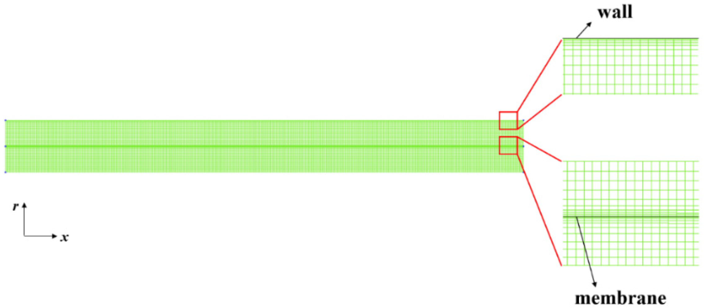
2.3. Geometry and Boundary Conditions

The internal radii of the quartz tube and the membrane tube are set as 10 and 5 mm, respectively. The tube length is 10 cm. The membrane thickness is 1 mm. The density and the thermal conductivity of the membrane are taken as 6000 kg/m3 and 4 W/(m·K), respectively [7]. The emissivity of the membrane and the quartz tube walls are set to 0.8 [7]. These parameters are summarized in Table 1.
The geometry is divided into two flow zones, one for the hydrogen generation side, the feed zone, and the other side, the sweep zone. The two zones are separated by a wall serving as the membrane. Each zone has inlet and outlet boundaries. The mass flow inlet conditions are specified at the inlet boundary of the feed and sweep zones, while the pressure outlet conditions are specified for the two outlet cross-sections. A mixture gas of H2, O2 and N2 with a fixed molar ratio of 0.4/0.2/0.4 is supplied to the feed side, and the mass flow rate of the feed gas is fixed at 5 × 10⁻⁶ kg/s. While CH4 in the mixture with CO2 is introduced to the sweep side with a varied composition and flow rate. The wall of the the quartz tube is assumed to be adiabatic. The pressures of the inlet gas streams are assumed to be 1 atm for the two sides. Table 2 gives the variation range of the boundary condition parameters in the subsequent parametric studies.
The effect of change in the sweep gas flow rate is investigated while keeping the mass ratio of CH4/CO2 at 0.2/0.8 and the inlet temperature of the two sides at 1073 K. In a similar fashion, the effect of change in the CH4/CO2 mass ratio is investigated while keeping the sweep gas flow rate at 1 × 10⁻⁷ kg/s and the inlet temperature at 1073 K. Lastly, the effect of the change in the inlet temperature is investigated while keeping the sweep gas flow rate at 1 × 10⁻⁷ kg/s and the CH4/CO2 mass ratio at 0.2/0.8. The sweep gas flow rate of 1 × 10⁻⁷ kg/s, the CH4/CO2 mass ratio of 0.2/0.8, and the inlet temperature of 1073 K are the base case values.

2.4. Solution Procedures

The commercial CFD software FLUENT is used to simulate the coupling process of hydrogen generation and methane combustion in the water splitting membrane reactor. Due to the symmetry nature of the reactor around its axis, the geometry is modelled as a two-dimensional axisymmetric unit. The segregated solver is used for solving the governing equations, while a steady state is considered. The Reynolds numbers in the feed side and the sweep side are approximately 12.37 and 2.90, respectively. Therefore, the laminar flow is considered. The energy model is used to solve the energy equation. The discrete ordinate model is considered for radiation. The incompressible ideal gas assumption is made for all the gases. The laminar finite-rate chemical kinetics model is used to simulate the volumetric reactions. The SIMPLE Pressure–Velocity coupling scheme is chosen. The Second Order Upwind discretization scheme is used for pressure, momentum, energy, species, and the discrete ordinate model. The convergence criteria for all the species, continuity, momentum, and energy residuals are set as 10−9.
Two numerical models are utilized in the present work. The first model is the water splitting reaction to produce hydrogen and oxygen permeation through the OTM using the set of Equations (7)–(14). These equations are defined in the FLUENT via a series of user-defined functions (UDFs) written in C++ language; the code is then compiled and connected to the FLUENT software. The second model in the present work is the chemical kinetics model of methane combustion (Equations (16)–(18)), which can be simulated by using the laminar finite-rate model in the FLUENT and be set directly in FLUENT panel using the default data from the FLUENT database. There are heat and mass transfers between the feed and sweep sides, which couple the two models. This coupling is achieved by adding the mass sink/source term in the continuity equation, as well as the species balance equation and the energy source in the energy conservation equation. In order to ensure the accuracy of the numerical solution, a grid independence test is carried out. The profile of the mesh distribution and refinement is given in Figure 2. As shown in the Figure 2, a structured mesh is used with 29,336 quadrilateral cells. Grid refinement is performed on the regions near the outer wall and the regions adjacent to each side of the membrane where the gradient is relatively high. In addition, the numerical model is validated with the available experimental data in the literature, as presented in the next section.

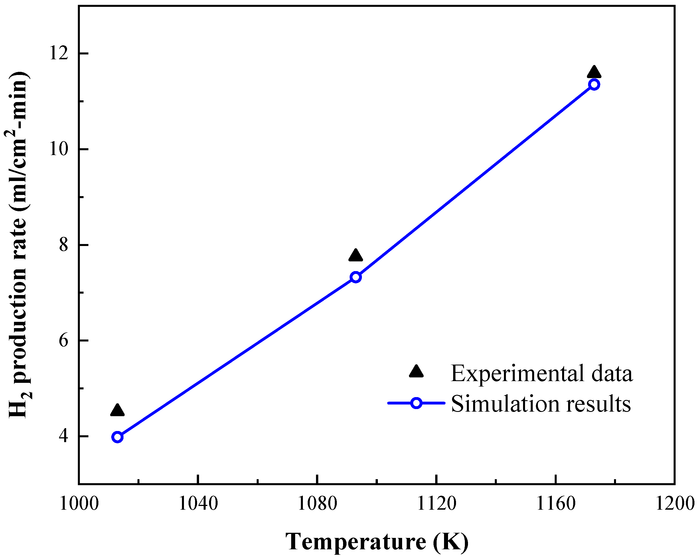
3. Validation of the Model

Due to the lack of experimental data fitted to the flow configuration described in the present work, a second model with the geometry used by Park et al. [8] was established to represent the experimental setup for the validation of the water splitting model. The simulation results of the second model were compared with the the experimental data by Park et al. The schematic diagram of the second model is given in Figure 3. As shown in this figure, a LSCuF−7328 membrane disk was affixed to one end of an Al2O3 tube, then they were placed inside a larger Al2O3 tube with one side of the membrane (defined as the feed side) exposed to the humidified nitrogen (N2/H2O = 0.51/0.49) and the other side (defined as the sweep side) exposed to a mixture of hydrogen and helium (H2/He = 0.8/0.2) [26]. The membrane thickness is 0.05 mm and the diameter of the membrane disk is 12 mm. The flow rate for both the feed and sweep gases was 150 mL/min [27]. The pressures of the inlet gas streams were 1 atm for the two sides. The numerical calculations were carried out with the reported experimental conditions, and a mixture of H2 and O2 was used to substitute the water vapor (N2/H2/O2 = 0.51/0.327/0.163) in the simulation. The comparison of the H2 production rate between the simulation results and experimental data is shown in Figure 4. It can be seen that the hydrogen production is enhanced as the temperature increases. This is because increasing the operating temperature can shift the equilibrium of the water splitting reaction to generate oxygen and hydrogen, and also lead to a reduction in the membrane resistance to oxygen permeation, thereby the amount of hydrogen generated increases. The simulation results are in good agreement with the experimental data. When the temperature is 1093 K, the maximum deviation between the simulation results of the hydrogen production rate and the experimental data is approximately 12%, which suggests that the simulation model is appropriate for the numerical investigation of the hydrogen generation process via water splitting in an oxygen transport membrane reactor.

4. Results and Discussion

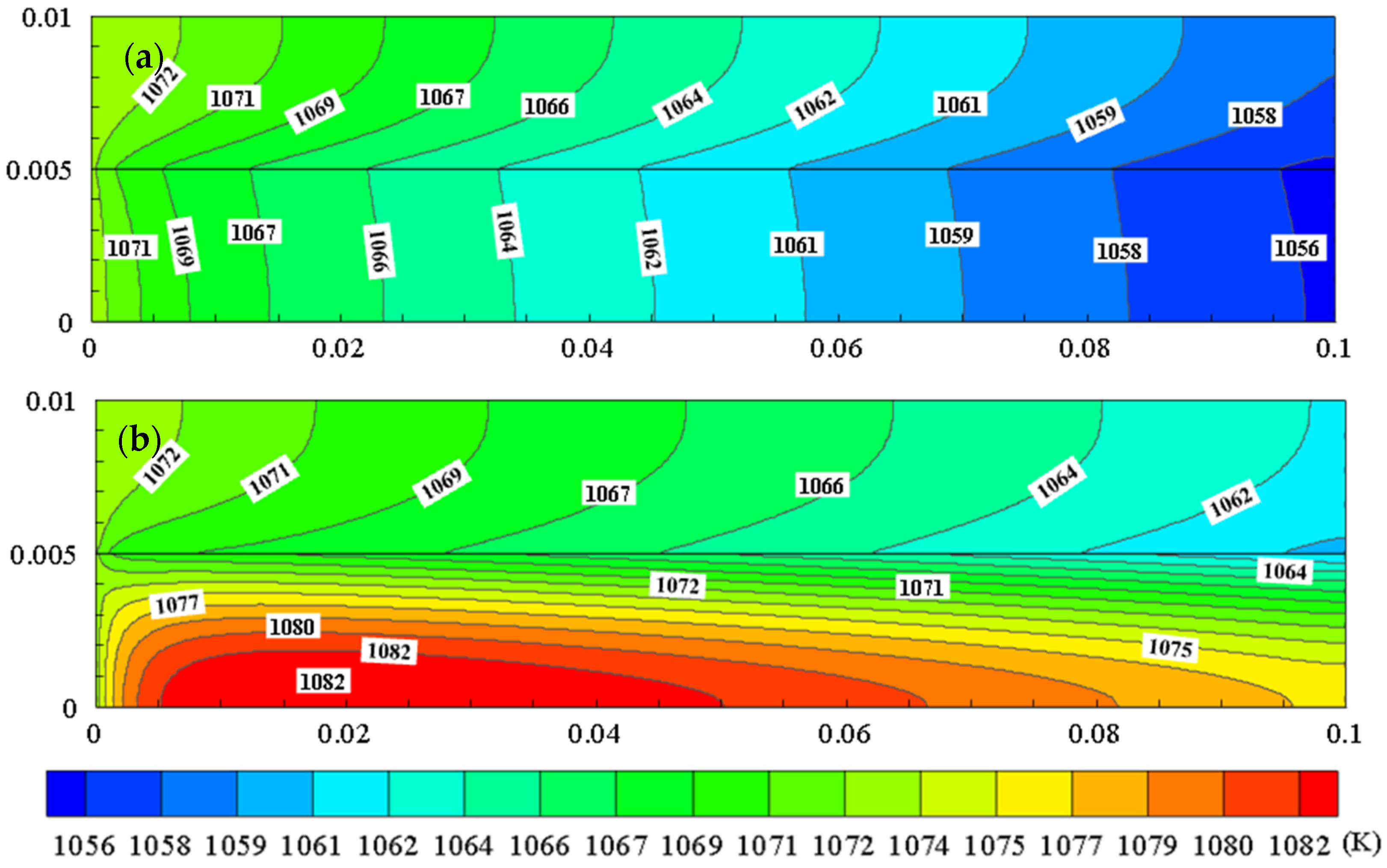
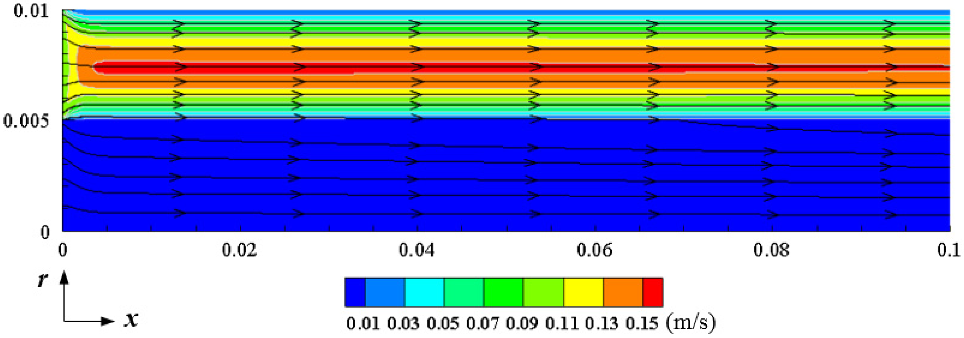
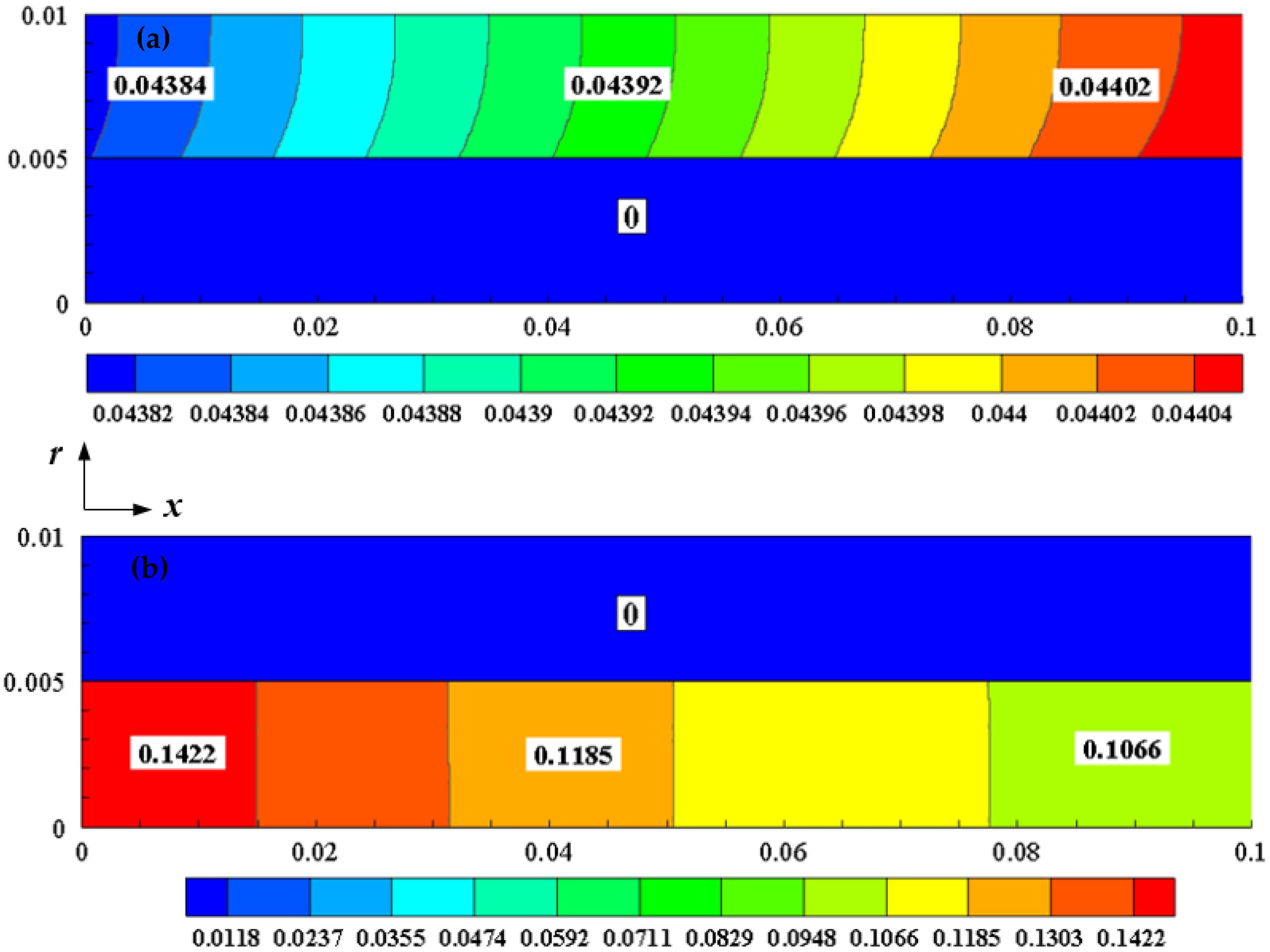
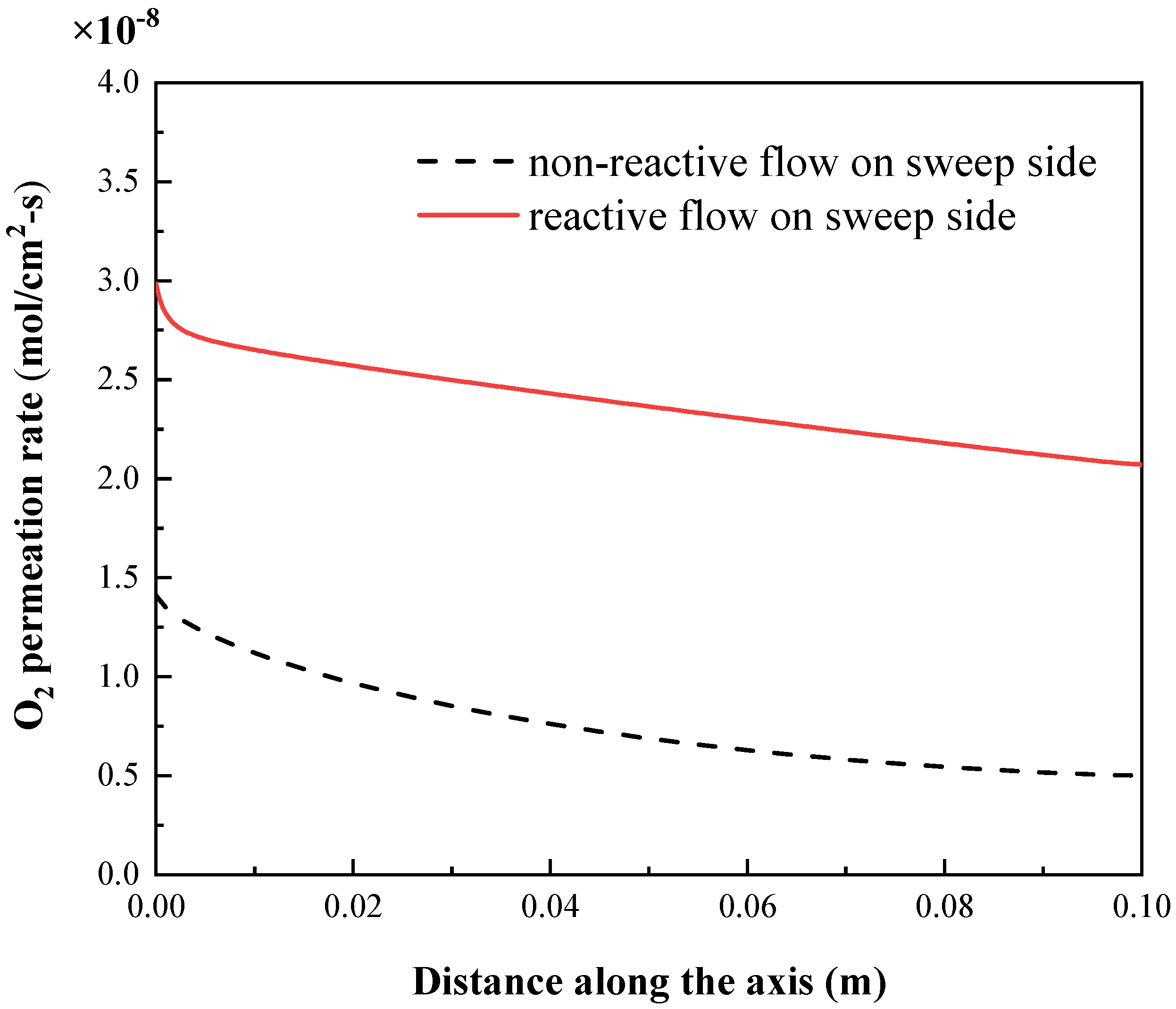
4.1. Comparison of Non−Reactive and Reactive Flow on Sweep Side

In this section, the results in terms of the temperature distribution and oxygen permeation rate under the non−reactive flow and reactive flow on the sweep side are compared. For the case of the non−reactive flow on the sweep side, CH4 is considered as an inert gas with no combustion reaction taking place on this side, the process only involves the water splitting and oxygen permeation. For the case of the reactive flow on the sweep side, all of the water splitting, oxygen permeation, and methane combustion occur in the membrane reactor. The two cases are under the same operating conditions taking the base case values of the boundary condition parameters described in Section 2.3.
The temperature contours of the membrane reactor for the two cases are depicted in Figure 5. It is found that when there is no methane combustion reaction on the sweep side in the radial direction, the closer to the OTM, the lower the temperature is. Additionally, the closer to the OTM, the larger the radial temperature gradient is on the feed side. Along the axis, the temperature gradually decreases from the inlet to the outlet. This is because the sweep gas continually takes away the oxygen across the membrane generated by the water splitting. The oxygen on the feed side is then continuously consumed, the water splitting equilibrium continues to move toward the direction of generating oxygen and hydrogen. Water splitting is a highly endothermic process, and the reaction mainly occurs in the area on the feed side adjacent to the membrane; therefore, the closer to the OTM, the lower the temperature is and the larger the radial temperature gradient is on the feed side. Due to the continuous endothermic reaction, the temperature gradually decreases along the length of the tube. When there is a methane combustion on the sweep side, in the radial direction, the closer to the OTM, the lower the temperature is due to the endothermic effect of the water splitting. The closer to the rotation axis, the higher the temperature is. Due to the exothermic methane combustion process, the temperature on the sweep side in the axial direction gradually rises and peaks at approximately 1/5 of the tube length. Then, the temperature gradually decreases due to the continuous permeation of low-temperature oxygen.
The flow pattern and velocity contour in the x−direction is provided in Figure 6. The contours of species concentrations (mass fraction of H2 and CH4) are given in Figure 7. It can be seen that the closer to the wall or the membrane, the larger the velocity gradient is. In the feed side, the mass fraction of H2 increases along the length of the tube due to water splitting, and the closer to the membrane, the higher the H2 concentration is. (Because a mixture of H2 and O2 is adopted to substitute the water vapor in this simulation, the concentration of H2 is not zero at the inlet of feed side.) In the sweep side, the mass fraction of CH4 decreases along the length of the tube due to the combustion reaction with O2, and the closer it is to the membrane, the lower the CH4 concentration.
Figure 8 shows the distribution of the oxygen permeation rate for the two cases. It can be seen that when there is no combustion, the oxygen permeation rate along the length of the tube gradually decreases from 1.41 × 10⁻⁸ to 0.5 × 10⁻⁸ mol/cm2·s. The maximum permeation occurs at the inlet of the sweep side. This is because there is no oxygen in the sweep side inlet that provides the maximum oxygen partial pressure difference, the driving force for the permeation. As the oxygen gradually permeates into the sweep side, the difference in the oxygen partial pressure between the two sides gradually decreases; therefore, the oxygen permeation rate decreases along the tube length. When there is a methane combustion reaction, the oxygen permeation rate decreases gradually along the length of the tube. A maximum value of 2.99 × 10⁻⁸ mol/cm2·s is obtained at the inlet, and the value at the outlet is about 2.07 × 10⁻⁸ mol/cm2·s, which is significantly higher than in the case of no methane combustion. On the one hand, methane consumes part of the oxygen during the combustion process, which reduces the oxygen partial pressure on the sweep side, thereby increasing the oxygen partial pressure difference between the two sides. On the other hand, the heat released by the methane combustion increases the temperature of the reactor, thereby reducing the oxygen permeation resistance of the membrane; therefore, the oxygen permeation rate is higher compared to the rate without combustion. Clearly, hydrogen generation is directly related to the oxygen permeation rate. Hence, the improvement in the oxygen permeation rate will directly enhance the hydrogen generation. The averaged hydrogen production rate without the methane combustion is 1.86 × 10⁻⁸ mol/cm2·s, and it is 5.63 × 10⁻⁸ mol/cm2·s with combustion, which is a rate approximately three times higher than that of the former. Therefore, the coupling of methane combustion and water splitting reaction can significantly improve the hydrogen production capacity of the membrane reactor.

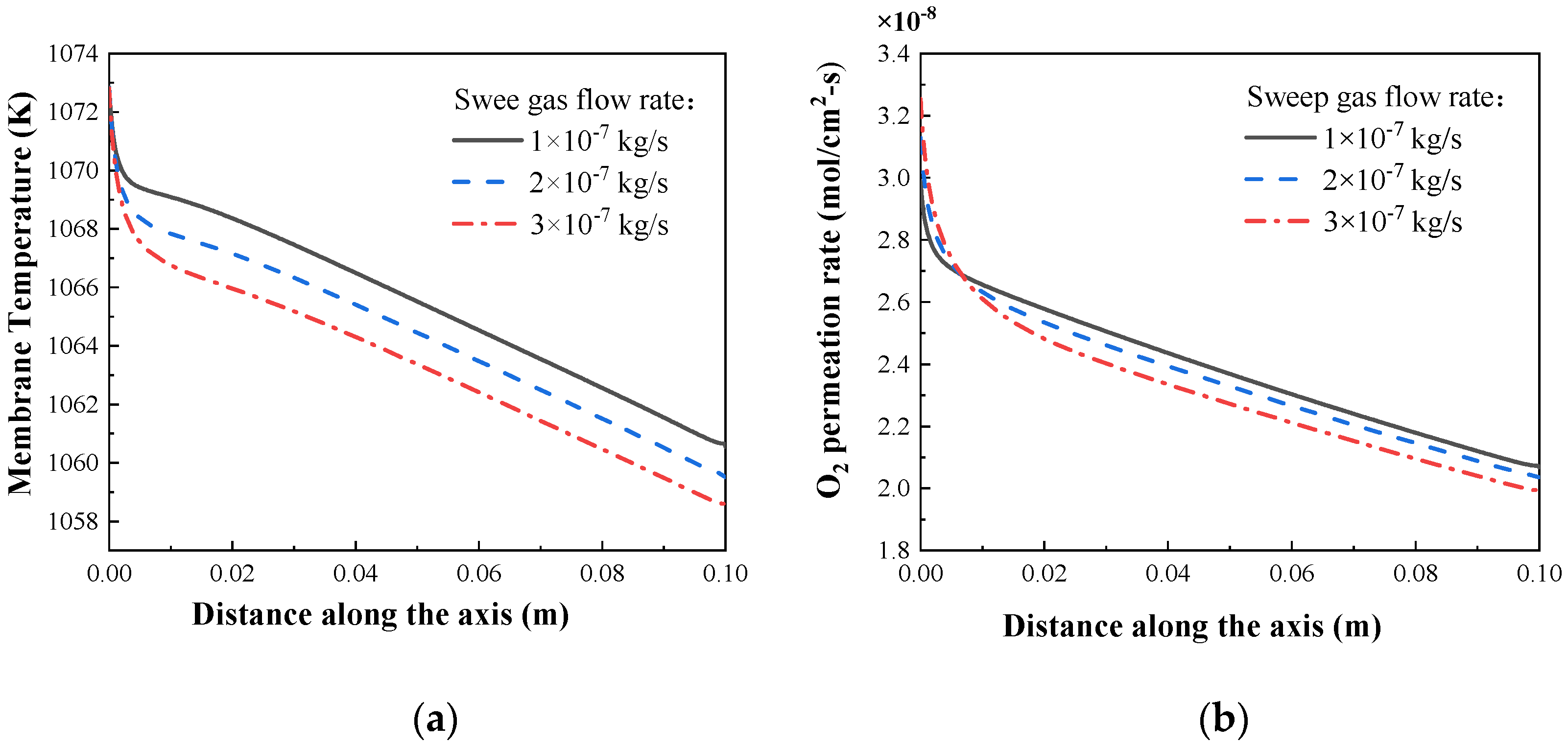
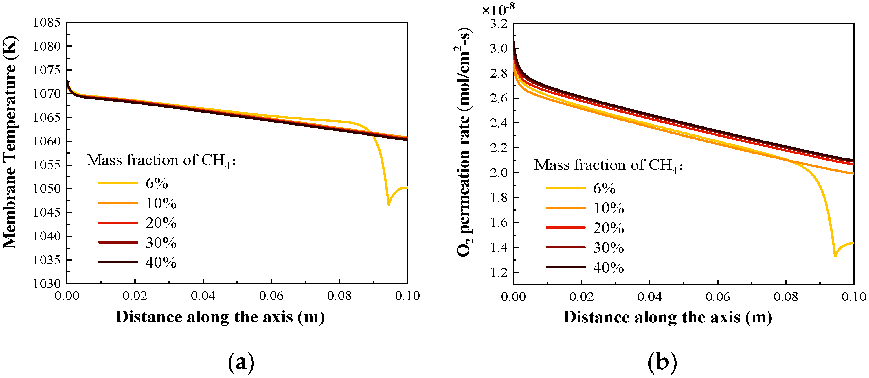
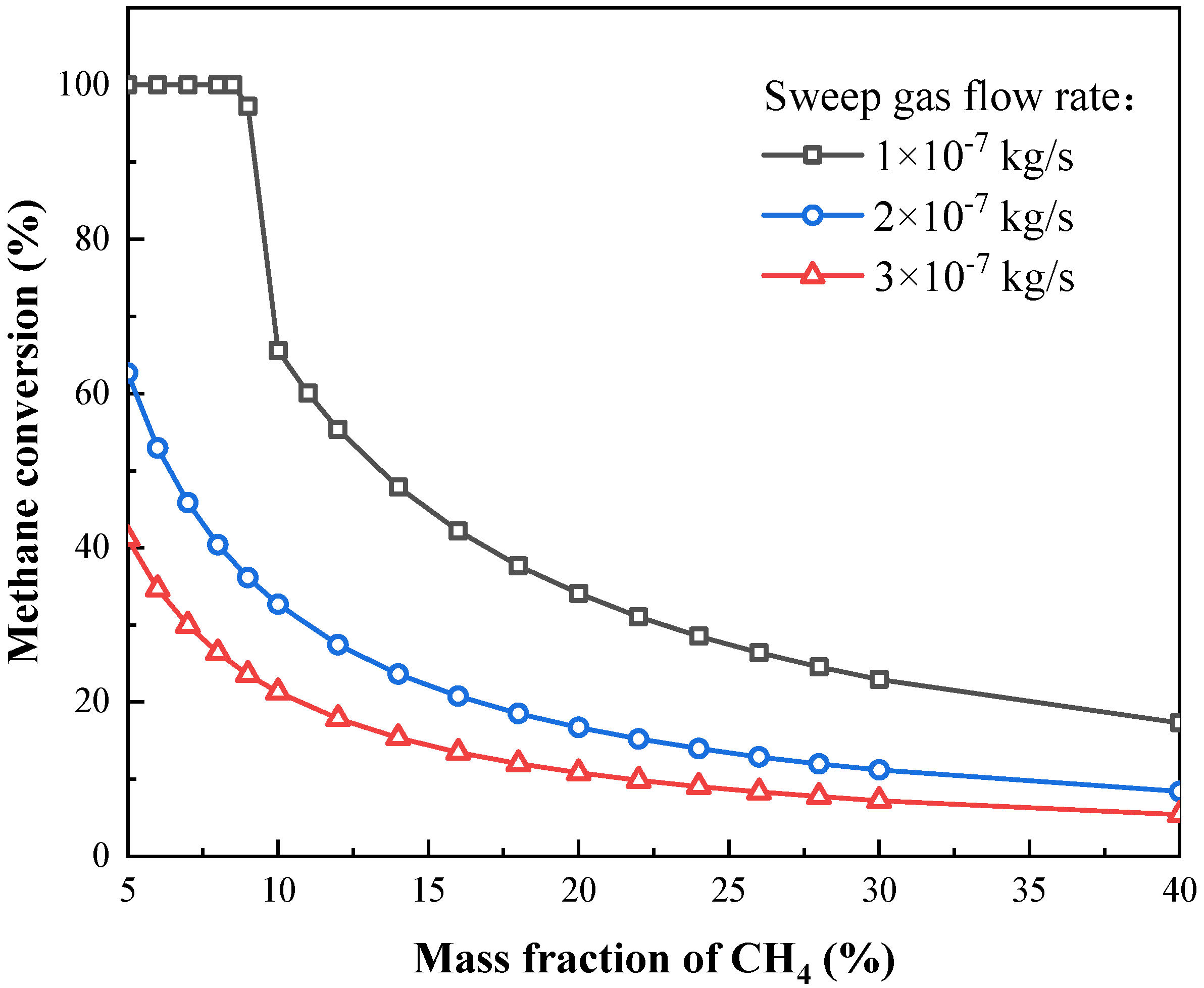
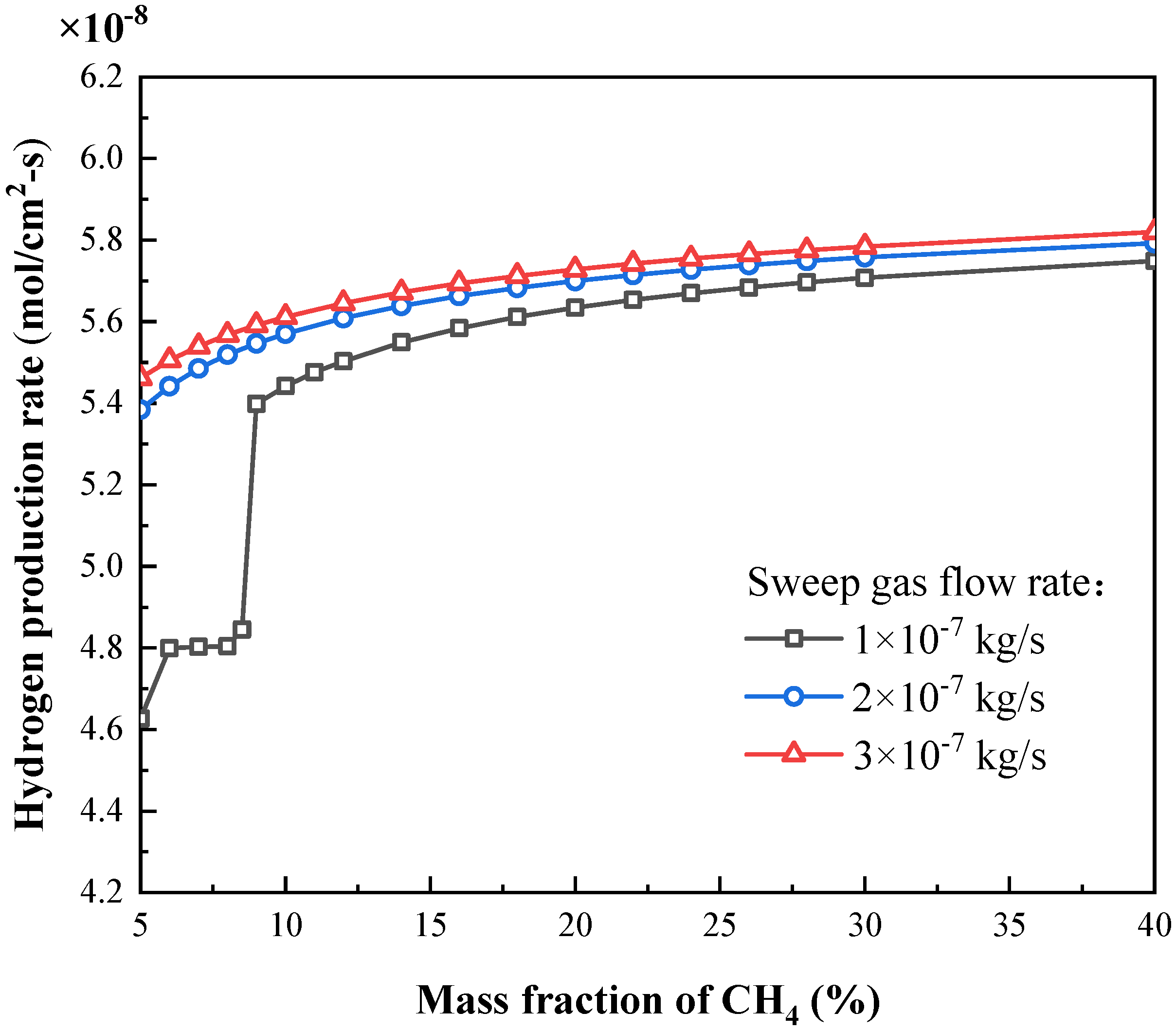
4.2. Effects of Sweep Gas Flow Rate and Fuel Composition

In this section, the effects of the sweep gas flow rate and fuel composition (i.e., methane content) are analyzed. The sweep gas (fuel) is a mixture of CH4 and CO2, where CO2 is used as a carrier gas to adjust the temperature.
Figure 9 shows the distributions of the membrane temperature and oxygen permeation rate along the axis at different sweep gas flow rates. It is found that the temperature of the OTM gradually decreases with the increase in the fuel flow rate. Along the tube length, the oxygen permeation rate first increases near the inlet and then decreases with the increase in the sweep gas flow rate. This is because, at the inlet, the amount of CH4 increases with the increasing sweep gas flow rate. Then, the amount of O2 consumed by CH4 increases, and thus the oxygen partial pressure difference between the two sides of the membrane increases. Therefore, the oxygen permeation flux first increases. However, as the oxygen permeating across the membrane increases, the equilibrium of the water splitting reaction accelerates toward the direction of generating oxygen and hydrogen. The reaction absorbs more heat and the membrane temperature decreases further. It takes 2 mol of H2O to produce 1 mol of O2, while only 0.5 mol of CH4 is required to consume 1 mol of oxygen. From a stoichiometric point of view, burning 1 mol of CH4 can promote the decomposition of 4 mol of H2O. However, according to the enthalpy changes in the water splitting and methane combustion reactions, e.g., at 1073 K, the enthalpy changes of these two reactions are 248.2 and −801.7 kJ/mol, respectively. It is found that the heat released by the combustion of 1 mol of methane is less than that absorbed by the decomposition of 4 mol of water vapor. Hence, the temperature in the reactor keeps decreasing with the proceeding of the reactions. After the inlet section, the influence of temperature on the oxygen permeation process is dominant, hence the oxygen permeation rate gradually decreases with the increase in the sweep gas flow rate thereafter.
Figure 10 presents the distribution of the membrane temperature and oxygen permeation rate along the axis at different methane mass fractions. When the methane content is low, such as 6% by mass, the membrane temperature reaches a minimum near the outlet and then increases slightly. At a low methane content, the methane is completely consumed with oxygen somewhere near the outlet. Due to the endothermic effect of water splitting on the other side, the membrane temperature drops to the lowest. Then, driven by the oxygen partial pressure difference between the two sides, the oxygen continues to permeate into the sweep side. At this time, the oxygen partial pressure in the sweep side begins to increase, and the partial pressure difference gradually decreases, and thus the oxygen permeation rate will decrease accordingly. Hence, the water splitting reaction starts to slow down, and the temperature rises slightly thereafter. When the methane content is high, due to the excessive amount of the gas in the fuel, methane cannot be exhausted in the reactor, hence there is no minimum peak in the membrane temperature. With the continuing increase in the methane content, the membrane temperature changes slightly. At a high methane content, the oxygen permeation rate also increases slightly with the increase in the methane mass fraction.
The change of methane conversion under different sweep gas flow rates and methane contents is presented in Figure 11. The methane conversion decreases with the increase in the sweep gas flow rate or methane content. At a sweep gas flow rate of 1 × 10⁻⁷ kg/s and methane mass fraction of less than 8.5%, the methane is completely consumed and the conversion is 100% due to the insufficient methane content. When the mass fraction exceeds 9%, the methane conversion begins to decrease due to the limited oxygen permeability of the membrane. When the mass fraction reaches 40%, the methane conversion decreases to 17.3%. When the sweep gas flow rate increases to 2 × 10⁻⁷ and 3 × 10⁻⁷ kg/s, and the methane content increases from 5% to 40%, the methane conversion decreases from 62.4% to 8.4% and from 41.2% to 5.4%, respectively. Since the methane conversion depends on the temperature and the amount of oxygen available for combustion, according to the above analysis, the membrane temperature decreases and the average oxygen permeation rate only has a slight increase. Hence, the methane conversion also decreases accordingly with the increase in the sweep gas flow rate. As the methane content increases, the oxygen permeation rate increases slightly, yet the increased amount of oxygen is not enough to consume the increased methane; therefore, the methane conversion also decreases.
Figure 12 shows the changes in the hydrogen production rate of the membrane reactor under different sweep gas flow rates and methane contents. It is found that the hydrogen production rate increases with the increase in the fuel flow rate and methane content. At a sweep gas flow rate of 1 × 10⁻⁷ kg/s and a methane mass fraction of less than 8.5%, the hydrogen production rate has a slight increase with the increase in methane content. When the methane content increases from 5% to 8.5%, the hydrogen production rate only increases from 4.63 × 10⁻⁸ to 4.80 × 10⁻⁸ mol/cm2·s. In this case, the amount of methane is insufficient, and the membrane temperature and oxygen permeation rate both show a low value, and thus the hydrogen production rate will be a very low value. As the mass fraction of methane increases from 8.5% to 9%, the hydrogen yield increases rapidly from 4.80 × 10⁻⁸ to 5.40 × 10⁻⁸ mol/cm2·s. As the methane content reaches 9%, it can be seen from Figure 11 that the methane content is similarly excessive; there is combustion reaction on the sweep side in the entire tube. Both the membrane temperature and oxygen permeation rate increase, hence the hydrogen production rate increases rapidly. After that, when the methane content increases to 40%, the hydrogen production rate only increases from 5.40 × 10⁻⁸ to 5.75 × 10⁻⁸ mol/cm2·s. That is to say, when the methane is excessive, the hydrogen production rate increases slowly with the increase in methane content. This is because the membrane temperature is almost unchanged at this time, and the oxygen permeation rate also increases slightly; therefore, the hydrogen production rate has a slight increase. When the methane is excessive, the hydrogen production rate also increases slightly with the increase in the sweep gas flow rate. When the flow rate increases from 1 × 10⁻⁷ kg/s to 2 × 10⁻⁷ and 3 × 10⁻⁷ kg/s and the methane content is 40%, the hydrogen production rate only increases from 5.75 × 10⁻⁸ to 5.79 × 10⁻⁸ and 5.82 × 10⁻⁸ mol/cm2·s, respectively. This is because at these flow rates, methane is excessive even when the mass fraction is 5%. Therefore, in order to ensure the hydrogen yield of the membrane reactor, the methane needs to be excessive. Additionally, due to the limited oxygen permeation capacity of the membrane reactor, when the methane is excessive, with continuous increase in the methane content or sweep gas flow rate, the hydrogen production rate only has a slight increase.

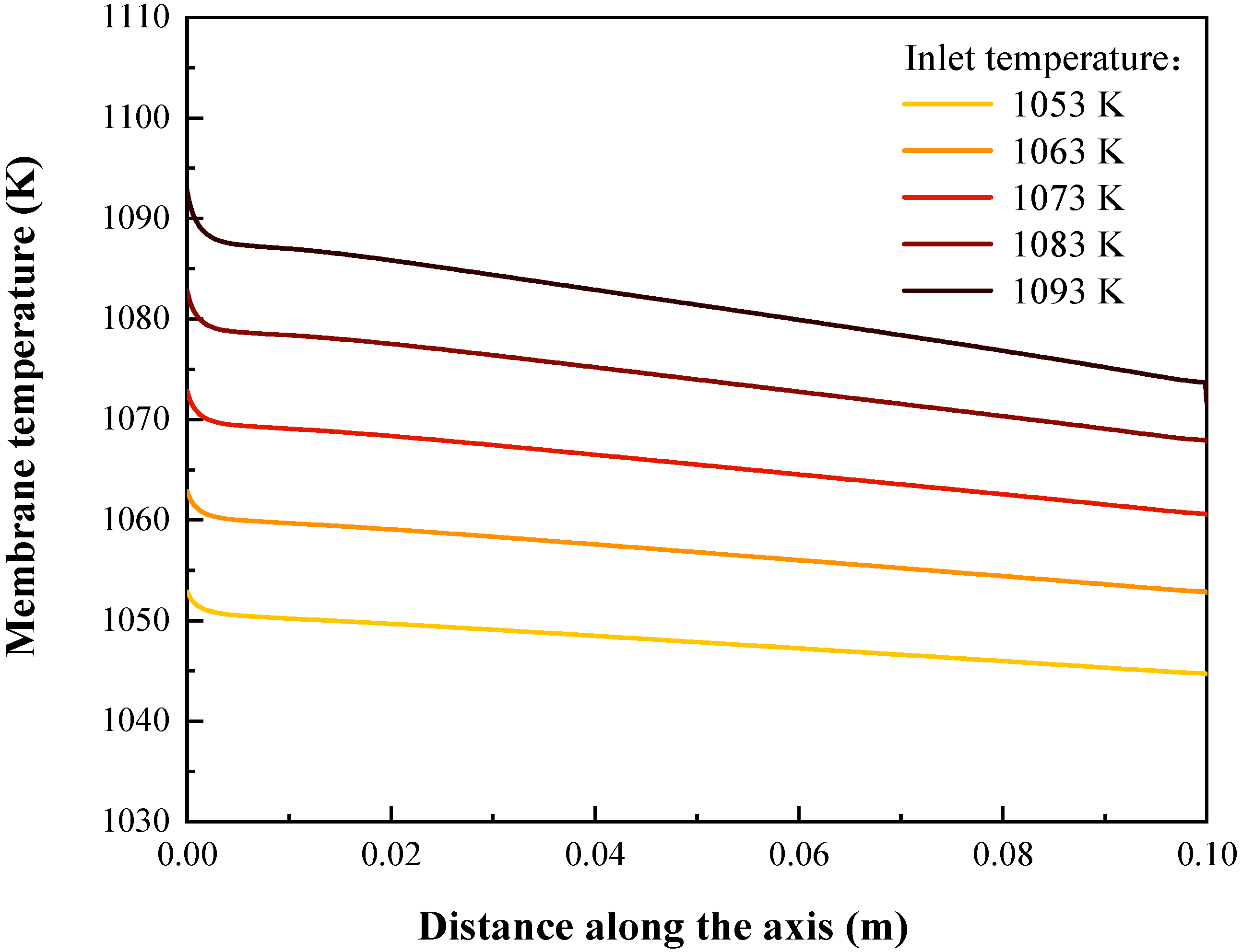
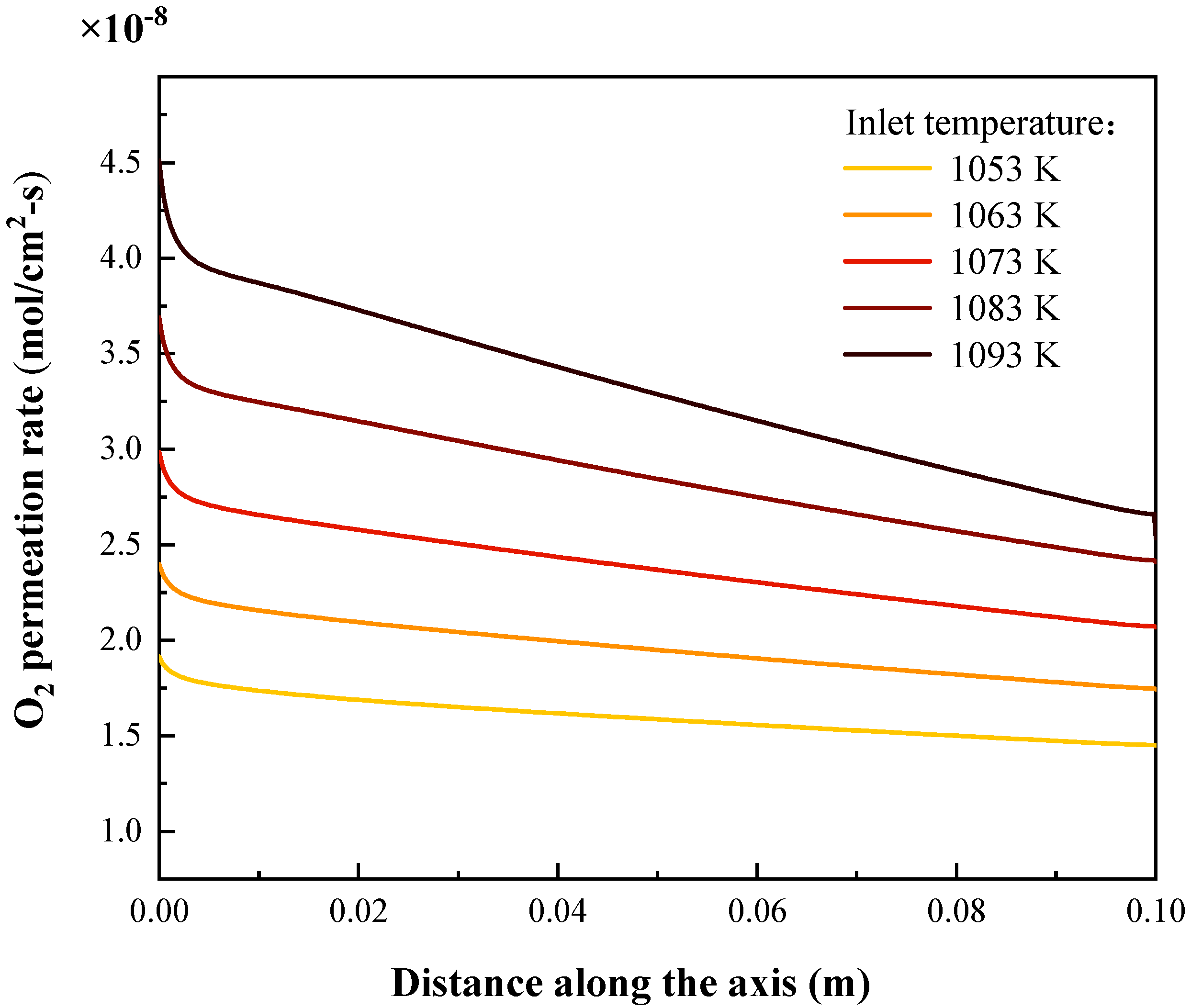
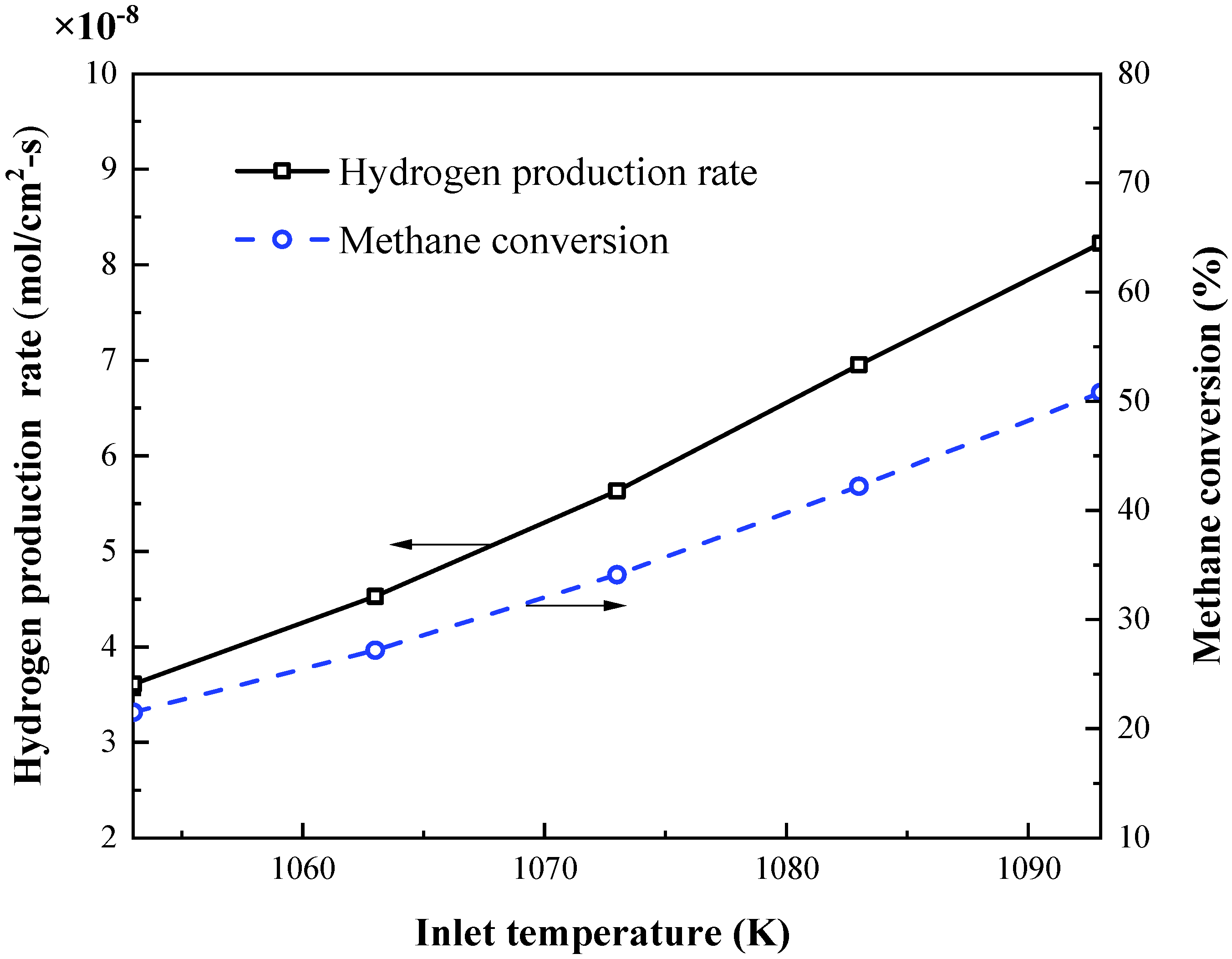
4.3. Effects of Inlet Temperature

In this section, the effects of the inlet gas temperature on the membrane temperature, the oxygen permeation rate, the hydrogen production rate, and the methane conversion are investigated. The inlet temperature of the sweep gas is the same as that of the feed gas.
Figure 13 shows the distribution of temperature along the axis at different inlet temperatures. It is found that as the reaction continues, the temperature of the OTM gradually decreases along the length of the tube. As the inlet temperature increases, the reaction rate of methane combustion increases, and the heat released by combustion also increases, hence the temperature of the membrane also increases. It is also found that the temperature difference between the reactor inlet and outlet increases as the inlet temperature increases. This is because the water splitting reaction is enhanced with the increase in the inlet temperature, and the heat absorbed by the reaction increases accordingly, hence the temperature of the membrane decreases more along the length of the tube.
Figure 14 shows the distribution of the oxygen permeation rate along the axis at different inlet temperatures. It can be seen that, as the inlet temperature increases, the oxygen permeation rate gradually increases due to the decrease in the oxygen permeation resistance. Along the axis, due to the decrease in the membrane temperature, the oxygen permeation rate gradually decreases. Additionally, the higher the inlet temperature is, the larger the difference in the oxygen permeation rate between the inlet and the outlet of the reactor. Figure 15 shows the hydrogen production rate, as well as the methane conversion rate, at different inlet temperatures. Since the temperature directly affects the oxygen permeation process, increasing the inlet temperature can consume more oxygen permeated from the feed side and enhance the water splitting reaction, and thus effectively increasing the hydrogen production rate. When the inlet temperature increases from 1053 to 1093 K, the hydrogen production rate increases from 3.61 × 10⁻⁸ to 8.23 × 10⁻⁸ mol/cm2·s, a 1.28-fold increase. In addition, the methane conversion also increases with the increase in the inlet temperature. When the inlet temperature increases from 1053 to 1093 K, the methane conversion increases from 21.5% to 50.8%.

5. Conclusions

A CFD simulation model for the coupled membrane reactor was developed by replacing the water vapor with a mixture of hydrogen and oxygen on the feed side, adding the energy source term on this side and adding a mass source term on both sides of the membrane, respectively, and the validity of the model was verified. The effects of the sweep gas flow rate, methane content and inlet temperature on the performance of membrane reactor were investigated when coupled with the methane combustion reaction. It is found that the coupling of methane combustion and water splitting can significantly improve the hydrogen generation capacity of the membrane reactor. Under certain conditions, the average hydrogen yield with methane combustion can be increased to three times, compared to the hydrogen yield without the methane combustion reaction. The methane conversion decreases with the increase in the sweep gas flow rate and methane content, while the trend of the hydrogen yield is opposite. In order to ensure the hydrogen yield of the membrane reactor, the methane needs to be excessive. Due to the limited oxygen permeability of the membrane reactor, when the methane is excessive, the hydrogen yield only increases slightly with the increase in the methane content or sweep gas flow rate. Increasing the inlet gas temperature can increase the membrane temperature, methane conversion, oxygen permeation rate and hydrogen yield.

Author Contributions

Conceptualization, T.Z. and C.C.; methodology, T.Z.; software, T.Z.; validation, T.Z.; investigation, T.Z.; writing—original draft preparation, T.Z.; writing—review and editing, T.Z. and H.Y.; visualization, T.Z.; supervision, H.Y. and C.C. All authors have read and agreed to the published version of the manuscript.

Funding

This research was funded by the National Natural Science Foundation of China, grant number U1832113.

Institutional Review Board Statement

Not applicable.

Informed Consent Statement

Not applicable.

Data Availability Statement

The data that support the findings of this study are available from the corresponding author upon reasonable request.

Conflicts of Interest

The authors declare no conflict of interest.

References

  1. Zhu, X.; Shi, C.Z.; Li, K.Z.; Zhai, K.; Wang, H.; Wei, Y.G.; Tian, D.; Zeng, C.H. Water splitting for hydrogen generation over lanthanum-calcium-iron perovskite-type membrane driven by reducing atmosphere. Int. J. Hydrogen Energy 2017, 42, 19776–19787. [Google Scholar] [CrossRef]
  2. Li, W.P.; Zhu, X.F.; Cao, Z.W.; Wang, W.P.; Yang, W.S. Mixed ionic-electronic conducting (MIEC) membranes for hydrogen production from water splitting. Int. J. Hydrogen Energy 2015, 40, 3452–3461. [Google Scholar] [CrossRef]
  3. Demirci, U.B.; Miele, P. Overview of the relative greenness of the main hydrogen production processes. J. Clean Prod. 2013, 52, 1–10. [Google Scholar] [CrossRef]
  4. Chaubey, R.; Sahu, S.; James, O.O.; Maity, S. A review on development of industrial processes and emerging techniques for production of hydrogen from renewable and sustainable sources. Renew. Sust. Energ. Rev. 2013, 23, 443–462. [Google Scholar] [CrossRef]
  5. Fang, W.; Steinbach, F.; Cao, Z.W.; Zhu, X.F.; Feldhoff, A. A highly efficient sandwich-like symmetrical dual-phase oxygen-transporting membrane reactor for hydrogen production by water splitting. Angew. Chem. Int. Ed. 2016, 55, 8648–8651. [Google Scholar] [CrossRef] [PubMed]
  6. Wei, Y.Y.; Yang, W.S.; Caro, J.; Wang, H.H. Dense ceramic oxygen permeable membranes and catalytic membrane reactors. Chem. Eng. J. 2013, 220, 185–203. [Google Scholar] [CrossRef]
  7. Nemitallah, M.A.; Habib, M.A.; Salaudeen, S.A.; Mansir, I. Hydrogen production, oxygen separation and syngas oxy-combustion inside a water splitting membrane reactor. Renew. Energ. 2017, 113, 221–234. [Google Scholar] [CrossRef]
  8. Park, C.Y.; Lee, T.H.; Dorris, S.E.; Balachandran, U. Hydrogen production from fossil and renewable sources using an oxygen transport membrane. Int. J. Hydrogen Energy 2010, 35, 4103–4110. [Google Scholar] [CrossRef]
  9. Hong, J.; Kirchen, P.; Ghoniem, A.F. Numerical simulation of ion transport membrane reactors: Oxygen permeation and transport and fuel conversion. J. Membr. Sci. 2012, 407, 71–85. [Google Scholar] [CrossRef]
  10. Habib, M.A.; Ahmed, P.; Ben-Mansour, R.; Badr, H.M.; Kirchen, P.; Ghoniem, A.F. Modeling of a combined ion transport and porous membrane reactor for oxy-combustion. J. Membr. Sci. 2013, 446, 230–243. [Google Scholar] [CrossRef]
  11. Ben-Mansour, R.; Habib, M.A.; Badr, H.M.; Nemitallah, M.A. Characteristics of oxy-fuel combustion in an oxygen transport reactor. Energ. Fuel. 2012, 26, 4599–4606. [Google Scholar] [CrossRef]
  12. Jiang, H.Q.; Liang, F.Y.; Czuprat, O.; Efimov, K.; Feldhoff, A.; Schirrmeister, S.; Schiestel, T.; Wang, H.H.; Caro, J. Hydrogen production by water dissociation in surface-modified BaCoxFeyZr1−x−yO3−δ hollow-fiber membrane reactor with improved oxygen permeation. Chem. Eur. J. 2010, 16, 7898–7903. [Google Scholar] [CrossRef]
  13. Lee, K.J.; Choe, Y.J.; Lee, J.S.; Hwang, H.J. Fabrication of a microtubular La0.6Sr0.4Ti0.2Fe0.8O3−δ membrane by electrophoretic deposition for hydrogen production. Adv. Mater. Sci. Eng. 2015, 2015, 505989. [Google Scholar] [CrossRef] [Green Version]
  14. Jiang, H.Q.; Wang, H.H.; Werth, S.; Schiestel, T.; Caro, J. Simultaneous production of hydrogen and synthesis gas by combining water splitting with partial oxidation of methane in a hollow-fiber membrane reactor. Angew. Chem. Int. Ed. 2008, 47, 9341–9344. [Google Scholar] [CrossRef]
  15. Jiang, H.Q.; Wang, H.H.; Liang, F.Y.; Werth, S.; Schirrmeister, S.; Schiestel, T.; Caro, J. Improved water dissociation and nitrous oxide decomposition by in situ oxygen removal in perovskite catalytic membrane reactor. Catal. Today 2010, 156, 187–190. [Google Scholar] [CrossRef]
  16. Wu, X.Y.; Ghoniem, A.F.; Uddi, M. Enhancing co-production of H2 and syngas via water splitting and POM on surface-modified oxygen permeable membranes. AIChE J. 2016, 62, 4427–4435. [Google Scholar] [CrossRef]
  17. Liang, W.Y.; Zhou, H.Y.; Caro, J.; Jiang, H.Q. Methane conversion to syngas and hydrogen in a dual phase Ce0.8Sm0.2O2-δ-Sr2Fe1.5Mo0.5O5+δ membrane reactor with improved stability. Int. J. Hydrogen Energy 2018, 43, 14478–14485. [Google Scholar] [CrossRef]
  18. Markov, A.A.; Merkulov, O.V.; Patrakeev, M.V.; Leonidov, I.A. Hydrogen and synthesis gas co-production on oxygen membranes of mixed conductor: Scale-sensitive features of the process. Int. J. Hydrogen Energy 2019, 44, 26807–26815. [Google Scholar] [CrossRef]
  19. Habib, M.A.; Salaudeen, S.A.; Nemitallah, M.A.; Ben-Mansour, R.; Mokheimer, E.M. Numerical investigation of syngas oxy-combustion inside a LSCF-6428 oxygen transport membrane reactor. Energy 2016, 96, 654–665. [Google Scholar] [CrossRef]
  20. Coltrin, M.E.; Glarborg, P. Chemically Reacting Flow: Theory and Practice; Wiley-Interscience: Hoboken, NJ, USA, 2003. [Google Scholar]
  21. Fluent, I. FLUENT 6.3 User’s Guide; Fluent Inc.: Lebanon, NH, USA, 2006. [Google Scholar]
  22. McGee, H.A. Molecular Engineering; McGraw-Hill: New York, NY, USA, 1991. [Google Scholar]
  23. Rui, Z.B.; Zhang, K.; Li, Y.; Lin, Y. Simulation of methane conversion to syngas in a membrane reactor: Part I A model including product oxidation. Int. J. Hydrogen Energy 2008, 33, 2246–2253. [Google Scholar] [CrossRef]
  24. Wang, H.; Gopalan, S.; Pal, U.B. Hydrogen generation and separation using Gd0.2Ce0.8O1.9δ−Gd0.08Sr0.88Ti0.95Al0.053O3±δ mixed ionic and electronic conducting membranes. Electrochim. Acta 2011, 56, 6989–6996. [Google Scholar] [CrossRef]
  25. Mancini, N.D.; Mitsos, A. Ion transport membrane reactors for oxy-combustion-Part II: Analysis and comparison of alternatives. Energy 2011, 36, 4721–4739. [Google Scholar] [CrossRef]
  26. Song, S.J.; Lee, T.; Wachsman, E.; Chen, L.; Dorris, S.; Balachandran, U. Defect structure and transport properties of Ni–SrCeO3− δ cermet for hydrogen separation membrane. J. Electrochem. Soc. 2005, 152, 125–129. [Google Scholar] [CrossRef]
  27. Lee, T.; Dorris, S.; Balachandran, U. Thin film preparation and hydrogen pumping characteristics of BaCe0.8Y0.2O3−δ. Solid State Ion. 2005, 176, 1479–1484. [Google Scholar] [CrossRef]
Figure 1. Schematic diagram of 2D axisymmetric representation of the coupled membrane reactor.
Energies 14 07175 g001
Figure 2. Profile of mesh distribution and refinement.
Energies 14 07175 g002
Figure 3. Schematic diagram of the second model used for validation.
Energies 14 07175 g003
Figure 4. Comparison of H2 production rate between simulation results and experimental data.
Energies 14 07175 g004
Figure 5. Temperature (K) contours under: (a) non−reactive and (b) reactive flow on sweep side (x/r = 0.4).
Energies 14 07175 g005
Figure 6. Flow pattern and velocity contour in x−direction under reactive flow (x/r = 0.4).
Energies 14 07175 g006
Figure 7. Contours of species concentrations under reactive flow: (a) mass fraction of H2; (b) mass fraction of CH4; (x/r = 0.4).
Energies 14 07175 g007
Figure 8. Distribution of O2 permeation rate under non−reactive and reactive flow on sweep side.
Energies 14 07175 g008
Figure 9. Effects of sweep gas flow rate on: (a) membrane temperature; (b) oxygen permeation rate.
Energies 14 07175 g009
Figure 10. Effects of methane content on: (a) membrane temperature; (b) oxygen permeation rate.
Energies 14 07175 g010
Figure 11. Methane conversion at different sweep gas flow rate and methane content.
Energies 14 07175 g011
Figure 12. Hydrogen production rate at different sweep gas flow rates and methane contents.
Energies 14 07175 g012
Figure 13. Effect of inlet temperature on membrane temperature.
Energies 14 07175 g013
Figure 14. Effect of inlet temperature on oxygen permeation rate.
Energies 14 07175 g014
Figure 15. Effects of inlet temperature on hydrogen production rate and methane conversion.
Energies 14 07175 g015
Table 1. Composition, dimensions, and physical parameters of membrane reactor.
Oxygen transport membraneLa0.7Sr0.3Cu0.2Fe0.8O3-δ (LSCuF−7328)
Effective length of membrane reactor10 cm
Internal radii of quartz tube10 cm
Internal radii of membrane tube5 cm
Thickness of membrane1 cm
Density of membrane6000 kg/m3
Thermal conductivity of membrane4 W/(m·K)
Emissivity of membrane and quartz tube0.8
Table 2. Variation range of boundary condition parameters in parametric studies.
Sweep Gas Flow Rate (kg/s)CH4/CO2 Mass RatioInlet Temperature (K)
--1053
1 × 10⁻⁷-1063
2 × 10−70.05/0.95~0.4/0.61073
3 × 10⁻⁷-1083
--1093
Publisher’s Note: MDPI stays neutral with regard to jurisdictional claims in published maps and institutional affiliations.

