Article

Numerical Study on the Influence of Vortex Generator Arrangement on Heat Transfer Enhancement of Oil-Cooled Motor

1
College of Civil Engineering, Tongji University, Shanghai 200092, China
2
School of Mechanical and Power Engineering, East China University of Science and Technology, Shanghai 200237, China
*
Authors to whom correspondence should be addressed.
These authors contributed equally to this work and should be considered co-first authors.
Energies 2021, 14(21), 6870; https://doi.org/10.3390/en14216870
Submission received: 25 September 2021 / Revised: 16 October 2021 / Accepted: 17 October 2021 / Published: 20 October 2021
(This article belongs to the Special Issue Numerical Heat Transfer and Fluid Flow 2021)

Abstract

:
At present, vortex generators have been extensively used in radiators to improve the overall heat transfer performance. However, there is no research on the effect of vortex generators on the ends of motor coils. Meanwhile, the current research mainly concentrates on the attack angle, shape and size, and lacks a detailed study on the transverse and longitudinal distance and arrangement of vortex generators. In this paper, the improved dimensionless number R is used as the key index to evaluate the overall performance of enhanced heat transfer. Firstly, the influence of the attack angle on heat transfer enhancement is discussed through a single pair of rectangular vortex generators, and the results demonstrate that the vortex generator with a 45° attack angle is superior. On this basis, we compare the effects of different longitudinal distances (2 h, 4 h, and 6 h, h meaning the height of vortex generator) on enhanced heat transfer under four distribution modes: Flow-Up (FU), Flow-Down (FU), Flow-Up-Down (FUD), Flow-Down-UP (FDU). Thereafter, the performances of different transverse distances (0.25 h, 0.5 h, and 0.75 h) of the vortex generators are numerically simulated. When comparing the longitudinal distances, FD with a longitudinal distance of 4 h (FD-4 h) performs well when the Reynolds number is less than 4000, and FU with a longitudinal distance of 4 h (FU-4 h) performs better when the Reynolds number is greater than 4000. Similarly, in the comparison of transverse distances, FD-4 h still performs well when the Reynolds number is less than 4000, and FU with a longitudinal distance of 4 h and transverse distance of 0.5 h (FU-4 h–0.5 h) is more prominent when the Reynolds number is greater than 4000.

Graphical Abstract

1. Introduction

The motor is widely used in ship, municipal, electric power, port handling, and other fields, with broad development prospects and considerable market capacity. In recent years, with the upgrading of power system requirements, the traditional motor with low efficiency and low power to weight ratio has been unable to meet the market demand, which has prompted the need for the research and development of new oil-cooled motors with high efficiency, high power density, low vibration and noise, and strong overload capacity [1,2]. During operation, the motor will produce immense heat, which will reduce the operating efficiency of the motor. In order to ensure the efficient operation of the motor, a heat exchanger is often used to enhance heat transfer and cool the motor. Fluid mediums in heat exchangers are diverse, and the oil phase is widely used because of its superior heat exchange effect, low cost, and long service life [3]. However, when the motor is compact, there will still be areas with a high temperature in the motor after the oil phase heat exchange [4,5]. For instance, in an oil-cooled motor, the temperature at the end of the coil outlet is higher than that of the iron core section, so further improving the heat transfer effect at the end of the coil outlet can enhance the performance of the whole motor [6,7,8]. Three ways are acknowledged to enhance heat transfer: increasing heat transfer area, increasing average temperature difference, and increasing the heat transfer coefficient [9]. According to the characteristics of coil oil cooling, the feasible heat transfer enhancement method of the coil end can be analyzed, and the vortex generator can be used to increase the heat transfer coefficient [10].
As a passive heat transfer enhancement technology, the vortex generator can produce vortexes to effectively improve the heat transfer rate of the heat transfer system. Because of its economy and convenience, it has attracted extensive attention in recent years. When it was initially proposed, it was mainly used in the field of aerodynamics [11]. Later, Johnson and Joubert [12] studied the heat transfer enhancement effect of the delta wing vortex generator on the air of the heat exchanger, which initiated the application of the vortex generator in the field of heat exchangers. Chai et al. [13] investigated the improvement of heat exchanger performance via the installation of vortex generators, based on the mechanism of the longitudinal vortex destroying the growth of the boundary layer, increasing the turbulence intensity, and producing secondary fluid flow on the heat transfer surface. There are various structures of vortex generators, such as rectangular wing, triangular wing, trapezoidal wing, cylindrical trapezoidal wing, cylindrical triangular wing, cylindrical rectangular wing, and so on [14,15,16,17]. Promvonge et al. [18] studied the influence of the vortex generator, combined with a fin and airfoil, on the heat transfer and drag characteristics of the flow passage under the condition of uniform heat flow boundary. The results showed that the heat transfer efficiency and friction loss of the fluid with the fin and airfoil vortex generator were higher than those with a smooth channel. Chen et al. [19] optimized the aspect ratio of the fluid channel and the height of the vortex generator. The results showed that, in a fluid channel with a large aspect ratio, the heat transfer performance could be enhanced while reducing the pressure loss. So far, many scholars have done a lot of research on the size and attack angle of vortex generators [20,21,22,23,24,25]. Wijayanta et al. [26] used the k - ε turbulence model to explore the heat transfer and pressure drop characteristics of vortex generators with various attack angles, and found that the maximum increases in Nusselt number and friction coefficient are 269% and 10.1 times higher than those of smooth tubes, respectively. Zhang et al. [27,28] explored the best combination of length, width, and longitudinal distance of the vortex generator, and its total efficiency was 7.2% higher than that without the vortex generator. Ebrahimi et al. [29,30] studied the heat transfer and fluid characteristics in the laminar flow channel installed with the vortex generator. It was noted that the channel of the vortex generator had higher efficiency, the friction coefficient increased by 2–25%, and the Nusselt number increased by 4–30%.
So far, the application of the vortex generator to enhance heat transfer has mainly been used in the heat exchanger, and air is primarily used as the fluid medium. In addition, the current research on the heat transfer of the vortex generator mainly focuses on the attack angle, size, and shape. However, only a few studies roughly explore the influence of the longitudinal distribution mode of the vortex generator on heat transfer, while there is a lack of detailed and orderly analysis and research on the specific longitudinal and transverse distribution mode of the vortex generator. Therefore, it is of great significance to study the arrangement of the vortex generator on the coil in the motor with oil as the fluid medium. With the help of computational fluid dynamics (CFD) software, the effect of different distribution types of the vortex generator on the heat transfer effect can be simulated, and the temperature change at the end of the coil and the pressure loss before and after the installation of the vortex generator can be analyzed. At the same time, the best distribution type can be obtained, and the mechanism of heat transfer enhancement by turbulence at the end of the coil can be revealed. Thus, through these explorations, this paper can provide a feasible idea for the design and application of the motor in industrial manufacturing.

2. Materials and Methods
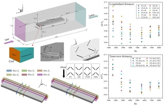
2.1. Physical Model

As shown in Figure 1a, a three-dimensional rectangular fluid channel is built on the basis of the rectangular coil. The length of the fluid channel is 888 mm , while the height and width of the inlet and outlet are 245 mm . Besides, the length, width, and height of the rectangular coil are 365 mm , 85 mm , and 20 mm respectively, and the distance from the rectangular coil to the inlet and outlet is 261.5 mm , and the distance to the upper and lower boundaries is 112.5 mm . Moreover, as illustrated in Figure 1b, the rectangular coil is composed of copper wire surrounded by a 0.5 mm thick insulating layer.
Figure 1c shows the detailed data of the vortex generator. The length and width of vortex generators are 30 mm , 1 mm respectively, while the height, which is defined as h , of the vortex generator, is 7.5 mm . Furthermore, the attack angle of the vortex generator is defined as α , and the distance between each pair of wings is 15 mm . As presented in Figure 1d, when investigating the best arrangement of the vortex generator, the longitudinal distance between two adjacent vortex generators is x , while the transverse distance is defined as y . Additionally, besides the variety of the longitudinal and transverse distance, four different vortex generator distribution modes are shown in Figure 1e, which are specified as Flow-Up (FU), Flow-Down (FD), Flow-Up-Down (FUD), Flow-Down-UP (FDU). It is worth noting that when investigating the influence of vortex generator arrangement on heat transfer performance, this paper first explores x = 2 h , 4 h , 6 h and four different distribution modes to obtain a better longitudinal distance and distribution mode. On this basis, y = 0.25 h , 0.5 h , 0.75 h are discussed to explore the influence of the transverse distance of vortex generator on heat transfer. Based on the above results, a relatively better heat transfer arrangement can be obtained.
When discussing and analyzing the effect of vortex generator arrangement on heat transfer, there are six different slices in X and Z directions, specified as Slice X 1 , Slice X 2 , Slice X 3 , Slice Z 1 , Slice Z 2 , Slice Z 3 . The X coordinates of Slice X 1 , X 2 , and X 3 were −40 mm , −10 mm , and 20 mm separately, while the Z coordinates of Slice Z 1 , Z 2 , and Z 3 were 10 mm , 25 mm , and 42.5 mm respectively. On this foundation, the straight line 3.75 mm above the coil is selected on the slice to obtain the temperature data to explore the uniformity of temperature distribution. Since only one pair of vortex generators are used to discover the change of attack angle, while two pairs of vortex generators are used to explore the distance and arrangement, the position of the slice relative to the vortex generator changes slightly, which can be observed in Figure 1f,g.

2.2. Materials

Table 1 illustrates the materials and properties of all parts of the physical models [31,32].

2.3. Governing Equations

No. 25# transformer oil is used as the working fluid, due to its good viscosity temperature property. Considering that the temperature change in the whole fluid domain is very small, the viscosity of oil is assumed to be constant. As pointed out by Chai et al. [13], the standard k - ε turbulence model is the most widely used and validated model, so the standard k - ε turbulence model is used as the mathematical model for numerical simulation, the near-wall treatment is enhanced wall treatment, and the governing equations include continuity equation, momentum equation, and energy equation, which are expressed as follows:
Continuity equation:
x i ( ρ o u i ) = 0
Momentum equation:
t ( ρ o u i ) + x w ( ρ o u i u w ) = x w ( μ λ o u i x w ρ o u i u w ¯ ) p x i
Energy equation:
x t ( ρ o T ) + x i ( ρ o u i T ) = x i ( λ o C p T x i ρ o u i T ¯ )
k equation:
t ( ρ o k ) + x i ( ρ o k u i ) = x w μ + μ t σ k k x w + G ρ o ε
ε equation:
t ( ρ o ε ) + x i ( ρ o ε u i ) = x w μ + μ t σ ε ε x w + C 1 ε k G C 2 ρ o ε 2 k

2.4. Boundary Conditions

As shown in Table 2, the inlet boundary is the velocity inlet with a speed range of 0.04 to 0.2 m / s , the outlet is the pressure outlet, and the relative pressure is 0. For the no-slip wall conditions used for the wall, the specific material properties can be referred to in Table 1.

2.5. Simulation Method and Initial Conditions

The commercial software FLUENT 17.1 is used to simulate the heat transfer process, and the finite volume method is used as the governing equation. The simple algorithm is used to realize the coupling between pressure and velocity. The second order upwind scheme is used for the momentum and energy equations. The convergence residuals of the velocity dependent equation and the energy dependent equation are less than 10 6 . The initial conditions are heating capacity of 392,857 w / m 3 , the initial temperature of 303 K .

3. Grid Independence Test

As illustrated in Figure 2a, all models calculated in this paper use hexahedral mesh. When figuring out the grid near the wall, it is necessary to take the thickness of the boundary layer into account, thus the use of the dimensionless number Y plus is required for characterization [33]. When calculating the grid spacing of the first layer, Y plus = 1 is taken to obtain the grid spacing of the first layer. After the grid spacing of the first layer is determined as 0.02 mm, it is extended outward in the proportion of 1.1 ratio. Before the numerical simulation, the grid independence is analyzed with five grid numbers, i.e., 262 × 10 4 , 421 × 10 4 , 596 × 10 4 , 685 × 10 4 , and 799 × 10 4 . From Figure 2b, it can be observed that with the increase of the number of grids, the growth of N u and f gradually decreases. Besides, it can be seen from Figure 2c that the maximum temperature of copper wire decreases and the Δ P increases with the increase in grid number. When the number of grids is greater than 685 × 10 4 , the N u , f , maximum temperature, Δ P change little, and when the number of grids changes from 685 × 10 4 to 799 × 10 4 , the relative change rates are less than 0.3%. Therefore, considering the accuracy and calculation time, a grid number of 685 × 10 4 is adopted in the present study.

4. Results and Discussions

4.1. Parameter Definition

The Nusselt number ( N u ), Reynolds number ( Re ), Prandtl number ( Pr ), Colburn factor ( j ), and friction factor ( f ) are employed to describe the thermal and flow characteristics of the oil channel and are defined as
N u = h c D λ o
Re = ρ o u D μ
Pr = C p μ λ o
j = N u Re Pr 1 3
f = 2 Δ P D ρ o u 2 L
where Δ P is the pressure drop between the inlet and outlet of the test model.
In order to evaluate the overall performance considering both maximum temperature and fluid characteristics, the dimensionless number R , is improved in the study based on Zhou’s [14] research. The R is defined as
R = T 0 T 1 × j j 0 f f 0
where T 0 represents the maximum temperature of the coil without vortex generators, while T 1 represents the maximum temperature of the coil with different dislocations of vortex generators. Based on the dimensionless number R , the larger R is, the better the comprehensive performance will be.

4.2. Verification of Numerical Results

Since the numerical model of the smooth channel proposed in this paper is similar to the physical models presented by Ma et al. [34] and Zhou et al. [14], the N u , f of the numerical model and the experimental model are compared to verify the reliability of the numerical model. As is found in Figure 3a, the Nusselt numbers are in reasonable conformity with two correlations from Ma et al. and Zhou et al., with average deviations of 9.5% and 10.8%, respectively. Similarly, according to Figure 3b, the friction factors of the simulation results are in reasonable agreement with Ma and Zhou’s results, with average differences of 26.9% and 16.9%, separately. Therefore, it is credible that the numerical model and solution method in this study are reliable.

4.3. Effect of Attack Angle of the Vortex Generator

Four different attack angles of vortex generators are used to explore the best choice, the four models differ only in the attack angle, and the other control conditions are consistent. By comparing the performance of the R of vortex generator under four different attack angles of 15 ° , 30 ° , 45 ° , and 60 ° , a better attack angle can be obtained. Figure 4a shows the change of the R of vortex generators with different attack angles in the process of Re increasing. It can be seen that the R is very close when the attack angles are 30 ° and 45 ° , and both of them are better than 15 ° and 60 ° attack angles, which is similar to the law obtained by Lotfi et al. [35] and Gholami et al. [36] when studying the attack angles of vortex generators in the past. Considering that the maximum temperature has a greater impact on oil-cooled motors, when the R of different types have the same performance, the vortex generator with a lower maximum temperature is used for calculation and discussion. In order to more widely explore the effect of the vortex generator on the coil end heat transfer, we introduce the thermal enhancement factor Δ T T 0 , where Δ T represents the difference between the maximum temperature of the channel with vortex generator and the maximum temperature of the channel without vortex generator, and T 0 represents the maximum temperature of the channel without vortex generator. As presented in Figure 4b, the thermal enhancement factor Δ T T 0 of the 45 ° attack angle is higher than that of the 30 ° attack angle. Therefore, the 45 ° attack angle vortex generator is selected as the basis for subsequent exploration.
When the iterative error is less than 10 - 5 and the maximum temperature does not change, the calculation is considered to be completed, and the data required for temperatures, velocities, and slices are extracted and analyzed. Under steady state conditions, Figure 5 shows pictures of a smooth channel without vortex generator at Re = 3993, Figure 5a shows the streamline diagram at 3.75 mm above the coil. Corresponding to this is the temperature contour diagram shown in Figure 5b. Moreover, Figure 5c,d shows the point line diagrams of the temperatures of different points extracted from the slices in the X and Z directions, respectively. Figure 6 shows pictures of the channel after installing a pair of vortex generators with an attack angle of 45 degrees. In Figure 6a,b, it can be seen that the region with low velocity in the streamline diagram shows higher temperature in the temperature contour diagram. Comparing with Figure 5a,b, due to the addition of vortex generator, two vortexes are formed behind the vortex generator, and the velocity at the two vortexes is higher than that in the adjacent region to a certain extent; therefore, this area shows lower temperature in the temperature contour diagram. However, by observing Figure 6c,d, since the thermal conductivity of the solid is significantly higher than that of the oil phase, the temperature of the vortex generator is higher than that of the oil phase on the same section, so the temperature of the vortex generator increases obviously at the place where the vortex generator is placed. In the middle of the two wings of the vortex generator and the area where the fluid flows through the vortex generator, the heat dissipation is accelerated due to the generation of the vortex, and the temperature is significantly lower than that in Figure 5c,d.

4.4. Effect of Longitudinal Distance of the Vortex Generator

After selecting 45 ° as the better attack angle of the vortex generator, the best longitudinal distance and distribution mode are explored. In this part, two winglets of the vortex generator are symmetrically distributed, with a total of 12 different cases. Figure 7a–d shows the variation of the R of vortex generators with FU, FD, FUD, and FDU distribution modes at different longitudinal distances at different Re . Through comparing the performance of the R , it can be concluded that in the three distributions of FU, FD, and FUD, the performance of longitudinal distance of 4 h is better than that of 2 h and 6 h . Especially in the two cases of FU and FD, the performance of the longitudinal distance of 4 h is significantly better than that of 2 h and 6 h at small Re . However, in the case of FDU distribution, the performance of longitudinal distance of 4 h is similar to that of 6 h . Therefore, as shown in Figure 7e, comparing the five cases of FU- 4 h , FD- 4 h , FUD- 4 h , FDU- 4 h , and FDU- 6 h , the conclusion that when the Re is less than 4000, the comprehensive performance of FD- 4 h is the best, while when the Re is greater than 4000, FU- 4 h has a slight advantage over other cases can be summarized. Besides, according to Figure 8, it can be concluded that the thermal enhancement factor Δ T T 0 of FD- 4 h performs more prominent when the Re < 4000, while the FU- 4 h tends to be better when the Re > 4000, and the overall thermal performance can be improved by up to 10.2%.
Figure 9 and Figure 10 show pictures of FD- 4 h and FU- 4 h . By observing Figure 9a and Figure 10a, four vortexes are formed behind the vortex generator due to the installation of two pairs of vortex generators at this time. In FD- 4 h , the vortexes are created at the contracted two wings of the vortex generator and develop towards the center of the vortex generator, while in FU- 4 h , the vortexes are formed at the expanded two wings of the vortex generator and develop towards both sides of the vortex generator. Through analyzing Figure 9c,d and Figure 10c,d, it can be found that, in FD- 4 h , the flow velocity at the center of the vortex generator is relatively slow and the temperature is high, while in the vicinity of the center, due to the formation of the vortex, more energy loss and temperature drop are generated, whereas in FU- 4 h , the flow velocity at both sides of the vortex generator is relatively slow and the temperature is high, and the vortexes generated near both sides speeds up the heat dissipation and reduces the temperature. Moreover, due to the change of flow mode, the position of the highest temperature point on the section also changes. There are two symmetrical peaks in Slice Z 1 in Figure 10d, while the two peaks in Figure 9d are asymmetrical.

4.5. Effect of Transverse Distance of the Vortex Generator

Through the above research results, eight transverse distributions are explored based on FD- 4 h and FU- 4 h . Figure 11a,b illustrates the change of the R of FD- 4 h and FU- 4 h with different transverse distances under different Re . According to Figure 11a, compared with other transverse distances, FD- 4 h without transverse distance still performs best, while in Figure 11b, FU- 4 h - 0.5 h has slight advantages. Therefore, as shown in Figure 11c, by comparing FD- 4 h and FU- 4 h - 0.5 h , the results can be conducted that when the Re is less than 4000, the comprehensive performance of FD- 4 h is better, while when the Re is greater than 4000, the effect of FU- 4 h - 0.5 h is better than other situations. Furthermore, from Figure 12, the conclusion that when the Re < 4000, the thermal enhancement factor Δ T T 0 of FD- 4 h still performs better, while when the Re > 4000, the FU- 4 h - 0.5 h tends to have some gradual preponderance.
Since the FD- 4 h situation has been analyzed above, there will be no more details here, and only the FU- 4 h - 0.5 h situation will be discussed. Figure 13a shows the flow line diagram of FU- 4 h - 0.5 h , from which it can be found that the flow line in the center of the vortex generator is no longer a straight line, but a curve with secondary disturbance on the left side of the second pair of vortex generators. In addition, the vortexes generated on the right side of the two pairs of vortex generators have a superposition effect, which impacts the heat transfer effect. The temperature contour diagram of Figure 13b and the slice diagrams of Figure 13c,d verify the analysis of the streamline in Figure 13a, the lower temperatures at the left wing of the second pair of vortex generators and the rear area of the second pair of vortex generators can be obtained. In addition, compared with Figure 10, due to the influence of transverse distance, the maximum temperature in Slice X 2 in Figure 13c is no longer symmetrically distributed, but the temperature is higher on one side and lower on the other.

5. Conclusions

Equipped with vortex generators, the coil end aims to solve the local overheating of the oil-cooled motor, so as to increase the efficiency of the oil-cooled motor. The oil phase is used as the coolant in the fluid domain. Firstly, the numerical model is verified and compared with the experimental data in the references. On this basis, the improved dimensionless number R is used to optimize the attack angle, longitudinal distance, and transverse distance of the vortex generator. The main conclusions are shown below:
  • Compared with the vortex generators with attack angles of 15 ° and 60 ° , the vortex generators with attack angles of 30 ° and 45 ° have better enhanced heat transfer effect. The performances of 30 ° and 45 ° attack angles are almost the same. Nevertheless, from the point of view of the maximum temperature, the effect of the 45 ° vortex generator is better than that of the 30 ° vortex generator.
  • The effect of vortex generator with the longitudinal distance of 4 h is better than that of 2 h and 6 h . When the Reynolds number is less than 4000, the enhanced heat transfer performance of FD with a longitudinal distance of 4 h (FD- 4 h ) is more prominent, and when the Reynolds number is greater than 4000, the performance of FU with a longitudinal distance of 4 h (FU- 4 h ) is superior.
  • Through the numerical simulation of the transverse distance of FU- 4 h and FD- 4 h , it can be concluded that, when the Reynolds number is less than 4000, the enhanced heat transfer performance of FD- 4 h is extraordinary, and when the Reynolds number is greater than 4000, the improved heat transfer performance of FU with a longitudinal distance of 4 h and transverse distance of 0.5 h (FU- 4 h - 0.5 h ) is better.

Author Contributions

Conceptualization, J.Z. and B.Z.; methodology, J.Z. and B.Z.; software, J.Z., S.Y. and B.Z.; validation, J.Z. and B.Z.; formal analysis, J.Z. and B.Z.; investigation, J.Z. and B.Z.; resources, B.Z., S.Y. and X.F.; data curation, J.Z. and B.Z.; writing—original draft preparation, J.Z.; writing—review and editing, J.Z., B.Z., S.Y. and X.F.; visualization, J.Z.; supervision, X.F.; project administration, X.F.; funding acquisition, X.F. All authors have read and agreed to the published version of the manuscript.

Funding

This research was funded by the National Natural Science Foundation of China, grant number 51879191.

Institutional Review Board Statement

Not applicable.

Informed Consent Statement

Not applicable.

Data Availability Statement

The datasets used and analyzed during the current study are available from the corresponding author on reasonable request.

Acknowledgments

Not applicable.

Conflicts of Interest

The authors declare no conflict of interest.

Nomenclature

N u Nusselt number
Re Reynolds number
Pr Prandtl number
j Colburn factor
j 0 Colburn factor of smooth channel
f Darcy friction factor
f 0 Darcy friction factor of smooth channel
h c Convective heat transfer coefficient ( Wm 2 K 1 )
D Hydraulic diameter ( mm )
u Fluid velocity ( m / s )
C p Specific heat capacity ( Jkg 1 K 1 )
P Pressure ( Pa )
t Time ( s )
T Temperature ( K )
X , Y , Z Cartesian coordinates
G Turbulence generation term
C 1 , C 2 Constant number
k Turbulent kinetic energy
Greek letters
λ Thermal conductivity ( Wm 1 K 1 )
λ o Oil Thermal conductivity ( Wm 1 K 1 )
ρ Density ( kg / m 3 )
ρ o Oil density ( kg / m 3 )
μ Dynamic viscosity
ε Turbulent Dissipation Rate
μ t Turbulent viscosity coefficient
σ k , σ ε Constant number
Subscripts
i , w i , w = 1, 2, and 3, respectively, represent the components along the X , Y and Z axes

References

  1. Gundabattini, E.; Mystkowski, A.; Idzkowski, A.; Singh, R.R.; Solomon, D.G. Thermal Mapping of a High-Speed Electric Motor Used for Traction Applications and Analysis of Various Cooling Methods-A Review. Energies 2021, 14, 1472. [Google Scholar] [CrossRef]
  2. Divakaran, A.M.; Hamilton, D.; Manjunatha, K.N.; Minakshi, M. Design, Development and Thermal Analysis of Reusable Li-Ion Battery Module for Future Mobile and Stationary Applications. Energies 2020, 13, 1477. [Google Scholar] [CrossRef] [Green Version]
  3. Ha, T.; Han, N.G.; Kim, M.S.; Rho, K.H.; Kim, D.K. Experimental Study on Behavior of Coolants, Particularly the Oil-Cooling Method, in Electric Vehicle Motors Using Hairpin Winding. Energies 2021, 14, 956. [Google Scholar] [CrossRef]
  4. Guo, F.L.; Zhang, C.N. Oil-Cooling Method of the Permanent Magnet Synchronous Motor for Electric Vehicle. Energies 2019, 12, 2984. [Google Scholar] [CrossRef] [Green Version]
  5. Lehmann, R.; Petuchow, A.; Moullion, M.; Kunzler, M.; Windel, C.; Gauterin, F. Fluid Choice Based on Thermal Model and Performance Testing for Direct Cooled Electric Drive. Energies 2020, 13, 5867. [Google Scholar] [CrossRef]
  6. Srinivasan, C.; Yang, X.; Schlautman, J.; Wang, D.; Gangaraj, S. Conjugate Heat Transfer CFD Analysis of an Oil Cooled Automotive Electrical Motor. SAE Int. J. Adv. Curr. Pract. Mobil. 2020, 2, 1741–1753. [Google Scholar] [CrossRef]
  7. Davin, T.; Pelle, J.; Harmand, S.; Yu, R. Experimental study of oil cooling systems for electric motors. Appl. Therm. Eng. 2015, 75, 1–13. [Google Scholar] [CrossRef]
  8. Saadi, M.S.; Ismail, M.; Fotowat, S.; Quaiyum, M.; Fartaj, A. Study of Motor Oil Cooling at Low Reynolds Number in Multi- Port Narrow Channels. SAE Int. J. Engines 2013, 6, 1287–1298. [Google Scholar] [CrossRef] [Green Version]
  9. Liu, S.; Sakr, M. A comprehensive review on passive heat transfer enhancements in pipe exchangers. Renew. Sust. Energy Rev. 2013, 19, 64–81. [Google Scholar] [CrossRef]
  10. He, Y.L.; Zhang, Y.W. Advances and Outlooks of Heat Transfer Enhancement by Longitudinal Vortex Generators. Adv. Heat. Transfer. 2012, 44, 119–185. [Google Scholar] [CrossRef] [Green Version]
  11. Schubauer, G.B.; Spangenberg, W.G. Forced mixing in boundary layers. J. Fluid Mech. 1960, 8, 10–32. [Google Scholar] [CrossRef]
  12. Johnson, T.; Joubert, P. The Influence of Vortex Generators on the Drag and Heat Transfer From a Circular Cylinder Normal to an Airstream. J. Heat Transf. 1969, 91, 1969. [Google Scholar] [CrossRef]
  13. Chai, L.; Tassou, S.A. A Review of Airside Heat Transfer Augmentation with Vortex Generators on Heat Transfer Surface. Energies 2018, 11, 2737. [Google Scholar] [CrossRef] [Green Version]
  14. Zhou, G.B.; Feng, Z.Z. Experimental investigations of heat transfer enhancement by plane and curved winglet type vortex generators with punched holes. Int. J. Therm. Sci. 2014, 78, 26–35. [Google Scholar] [CrossRef]
  15. Wu, J.M.; Tao, W.Q. Effect of longitudinal vortex generator on heat transfer in rectangular channels. Appl. Therm. Eng. 2012, 37, 67–72. [Google Scholar] [CrossRef]
  16. Aris, M.S.; McGlen, R.; Owen, I.; Sutcliffe, C.J. An experimental investigation into the deployment of 3-D, finned wing and shape memory alloy vortex generators in a forced air convection heat pipe fin stack. Appl. Therm. Eng. 2011, 31, 2230–2240. [Google Scholar] [CrossRef] [Green Version]
  17. Wu, J.M.; Tao, W.Q. Numerical study on laminar convection heat transfer in a rectangular channel with longitudinal vortex generator. Part A: Verification of field synergy principle. Int. J. Heat Mass. Trans. 2008, 51, 1179–1191. [Google Scholar] [CrossRef]
  18. Promvonge, P.; Chompookham, T.; Kwankaomeng, S.; Thianpong, C. Enhanced heat transfer in a triangular ribbed channel with longitudinal vortex generators. Energy Convers. Manag. 2010, 51, 1242–1249. [Google Scholar] [CrossRef]
  19. Chen, C.; Teng, J.T.; Cheng, C.H.; Jin, S.P.; Huang, S.Y.; Liu, C.; Lee, M.T.; Pan, H.H.; Greif, R. A study on fluid flow and heat transfer in rectangular microchannels with various longitudinal vortex generators. Int. J. Heat Mass. Trans. 2014, 69, 203–214. [Google Scholar] [CrossRef]
  20. Saha, P.; Biswas, G.; Sarkar, S. Comparison of winglet-type vortex generators periodically deployed in a plate-fin heat exchanger—A synergy based analysis. Int. J. Heat Mass. Trans. 2014, 74, 292–305. [Google Scholar] [CrossRef]
  21. Sinha, A.; Raman, K.A.; Chattopadhyay, H.; Biswas, G. Effects of different orientations of winglet arrays on the performance of plate-fin heat exchangers. Int. J. Heat Mass. Trans. 2013, 57, 202–214. [Google Scholar] [CrossRef]
  22. Min, C.H.; Qi, C.Y.; Kong, X.F.; Dong, J.F. Experimental study of rectangular channel with modified rectangular longitudinal vortex generators. Int. J. Heat Mass. Trans. 2010, 53, 3023–3029. [Google Scholar] [CrossRef]
  23. Eiamsa-ard, S.; Wongcharee, K.; Eiamsa-ard, P.; Thianpong, C. Heat transfer enhancement in a tube using delta-winglet twisted tape inserts. Appl. Therm. Eng. 2010, 30, 310–318. [Google Scholar] [CrossRef]
  24. Tian, L.T.; He, Y.L.; Lei, Y.G.; Tao, W.Q. Numerical study of fluid flow and heat transfer in a flat-plate channel with longitudinal vortex generators by applying field synergy principle analysis. Int. Commun. Heat Mass. 2009, 36, 111–120. [Google Scholar] [CrossRef]
  25. Kim, E.; Yang, J.S. An experimental study of heat transfer characteristics of a pair of longitudinal vortices using color capturing technique. Int. J. Heat Mass. Trans. 2002, 45, 3349–3356. [Google Scholar] [CrossRef]
  26. Wijayanta, A.T.; Aziz, M.; Kariya, K.; Miyara, A. Numerical Study of Heat Transfer Enhancement of Internal Flow Using Double-Sided Delta-Winglet Tape Insert. Energies 2018, 11, 3170. [Google Scholar] [CrossRef] [Green Version]
  27. Zhang, J.F.; Jia, L.; Yang, W.W.; Taler, J.; Oclon, P. Numerical analysis and parametric optimization on flow and heat transfer of a microchannel with longitudinal vortex generators. Int. J. Therm. Sci. 2019, 141, 211–221. [Google Scholar] [CrossRef]
  28. Zhang, J.F.; Wang, J.S.; Sun, J. Principles and Characteristics of Heat Transfer Enhancement on Small-scale Vortex Generators. Energy Conserv. Technol. 2006, 24, 399–401. [Google Scholar]
  29. Ebrahimi, A.; Rikhtegar, F.; Sabaghan, A.; Roohi, E. Heat transfer and entropy generation in a microchannel with longitudinal vortex generators using nanofluids. Energy 2016, 101, 190–201. [Google Scholar] [CrossRef]
  30. Ebrahimi, A.; Roohi, E.; Kheradmand, S. Numerical study of liquid flow and heat transfer in rectangular microchannel with longitudinal vortex generators. Appl. Therm. Eng. 2015, 78, 576–583. [Google Scholar] [CrossRef] [Green Version]
  31. Minakshi, M.; Blackford, M.; Ionescu, M. Characterization of alkaline-earth oxide additions to the MnO2 cathode in an aqueous secondary battery. J. Alloys Compd. 2011, 509, 5974–5980. [Google Scholar] [CrossRef] [Green Version]
  32. Wickramaarachchi, K.; Sundaram, M.M.; Henry, D.J.; Gao, X.P. Alginate Biopolymer Effect on the Electrodeposition of Manganese Dioxide on Electrodes for Supercapacitors. ACS Appl. Energy Mater. 2021, 4, 7040–7051. [Google Scholar] [CrossRef]
  33. Pugachev, A.O.; Ravikovich, Y.A.; Savin, L.A. Flow structure in a short chamber of a labyrinth seal with a backward-facing step. Comput. Fluids 2015, 114, 39–47. [Google Scholar] [CrossRef]
  34. Ma, J.; Huang, Y.P.; Huang, J.; Wang, Y.L.; Wang, Q.W. Experimental investigations on single-phase heat transfer enhancement with longitudinal vortices in narrow rectangular channel. Nucl. Eng. Des. 2010, 240, 92–102. [Google Scholar] [CrossRef]
  35. Lotfi, B.; Sunden, B.; Wang, Q.W. An investigation of the thermo-hydraulic performance of the smooth wavy fin-and-elliptical tube heat exchangers utilizing new type vortex generators. Appl. Energ 2016, 162, 1282–1302. [Google Scholar] [CrossRef]
  36. Gholami, A.A.; Wahid, M.A.; Mohammed, H.A. Heat transfer enhancement and pressure drop for fin-and-tube compact heat exchangers with wavy rectangular winglet-type vortex generators. Int. Commun. Heat Mass. 2014, 54, 132–140. [Google Scholar] [CrossRef]
Figure 1. (a) Diagrams of a channel with coil and vortex generators, (b) specific graph of the coil, (c,d) specific graphs of vortex generator, (e) four different distribution types, (f,g) slice diagrams in X and Z directions.
Energies 14 06870 g001
Figure 2. (a) Representative grids in numerical simulation, (b,c) grid independence test results.
Energies 14 06870 g002
Figure 3. Validation of numerical results (a) N u , (b) f .
Energies 14 06870 g003
Figure 4. Performance of (a) R and (b) thermal enhancement factor Δ T T 0 at different Re .
Energies 14 06870 g004
Figure 5. Diagrams of smooth channel under steady state conditions: (a) streamline diagram, (b) contour diagram of temperature, (c) slice temperature diagram in X direction, (d) slice temperature diagram in Z direction.
Energies 14 06870 g005
Figure 6. Diagrams of channel with 45 ° attack angle vortex generator under steady state conditions: (a) streamline diagram, (b) temperature contour diagram, (c) slice temperature diagram in X direction, (d) slice temperature diagram in Z direction.
Energies 14 06870 g006
Figure 7. Performance of R at different longitudinal distances (2 h, 4 h, and 6 h) and distribution modes, (a) FU; (b)FD; (c) FUD; (d) FDU and (e) relatively better distribution mode.
Energies 14 06870 g007
Figure 8. Performance of thermal enhancement factor Δ T T 0 at different Re .
Energies 14 06870 g008
Figure 9. Diagrams of FD- 4 h under steady state conditions: (a) streamline diagram, (b) temperature contour diagram, (c) slice temperature diagram in X direction, (d) slice temperature diagram in Z direction.
Energies 14 06870 g009
Figure 10. Diagrams of FU- 4 h under steady state conditions: (a) streamline diagram, (b) temperature contour diagram, (c) slice temperature diagram in X direction, (d) slice temperature diagram in Z direction.
Energies 14 06870 g010
Figure 11. Performance of R at different transverse distances (0.25 h, 0.5 h, and 0.75 h) and distribution modes, (a) FD-4h; (b) FU-4h; (c) relatively better distribution mode.
Energies 14 06870 g011
Figure 12. Performance of thermal enhancement factor Δ T T 0 at different Re .
Energies 14 06870 g012
Figure 13. Diagrams of FU- 4 h - 0.5 h under steady state conditions, (a) streamline diagram, (b) temperature contour diagram, (c) slice temperature diagram in X direction, (d) slice temperature diagram in Z direction.
Energies 14 06870 g013
Table 1. Materials and properties.
ModelsMaterials ρ   ( kgm 3 ) C p   ( Jkg 1 k 1 ) λ   ( wm 1 k 1 ) μ   ( kgm 1 s 1 )
Copper wireCopper8978381387.6-
Insulating layerPolymer11901.050.2-
Vortex generatorEpoxy12005502-
FluidOil87520930.1350.008
Table 2. Boundary conditions.
Boundary ConditionsMethodsValues
InletVelocity inlet0.04–0.2 m / s
OutletPressure outlet0 Pa
WallNo slip-
Publisher’s Note: MDPI stays neutral with regard to jurisdictional claims in published maps and institutional affiliations.

