Article

Control of WPT Transmitter Coils for Power Distribution to Two Receiver Coils without Feedback

1
Department of AI Convergence Network, Ajou University, Suwon 16499, Korea
2
Electronics and Telecommunications Research Institute, Daejeon 34129, Korea
3
Electronic Engineering, Hanyang University, Seoul 04763, Korea
4
Department of Electrical and Computer Engineering, Ajou University, Suwon 16499, Korea
*
Author to whom correspondence should be addressed.
Energies 2021, 14(20), 6828; https://doi.org/10.3390/en14206828
Submission received: 31 July 2021 / Revised: 17 September 2021 / Accepted: 14 October 2021 / Published: 19 October 2021
(This article belongs to the Special Issue Next Generation Wireless Charging System for Mobile Devices)

Abstract

:
This paper proposes the algorithm to control the current ratio of the transmitting (Tx) coils for proper power distribution to the two receiving (Rx) coils in wireless power transfer (WPT) system. The proposed algorithm assumes that each Rx coil appears at different times to consider the situation where multiple users request power transmission as practically as possible. That is, suppose the second Rx coil enters the charging space later than the first Rx coil. When each coil enters the charging space, only the Tx coil is used to obtain the value required for calculation. Using the obtained result, the optimized Tx coil current is calculated by the proposed algorithm and proper power distribution to both Rx coils is achieved. Three Tx coils and two Rx coils are constructed using the ANSYS MAXWELL simulation tool. As a result of applying the proposed algorithm, it was confirmed that a similar level of power was transmitted between 40∼60%, respectively. The sum of the power transmitted to the two Rx coils also appeared as more than 75%.

Graphical Abstract

1. Introduction

Wireless power transfer (WPT) system is used in various fields such as medical devices, vehicles, and mobile devices [1,2,3,4,5,6]. To make a sufficient charging area, a WPT system is constructed using a multiple transmitting (Tx) coil. In the case of a system with a single receiving (Rx) coil, the main concerns are a method of considering the misalignment between the Tx coil and the Rx coil, wireless charging in a three-dimensional space, and maximization of power transmission efficiency (PTE) [5,7,8]. It has already been shown that to transmit power to a single Rx coil with maximum efficiency, the current of the Tx coil must be set as the ratio of the coupling coefficient between the Tx and Rx coils [9,10]. Recently, the number of devices that need to be charged is increasing. For this reason, studies on the WPT system with multiple Rx coils have become more important.
For charging multiple Rx coils simultaneously, proper distribution of power is required. The power distribution has been performed by controlling the excitation of the Tx coil using a complex algorithm or by using an additional circuit or multiple channels [11,12,13,14]. In [11], a weight factor for received power is determined for each Rx coil, and the algorithm is designed to find the Tx coil current that maximizes the sum of the received powers. At a Tx-Rx coil distance of 20 cm, the PTE of 34% is achieved, and each received power also changes according to the change in weight factor, but the level of change is not linear with the weight, so improvement for the algorithm is needed. In [12], the Tx coil current was calculated using the target power of each of the two Rx coils, and as a result of simulation at a Tx-Rx distance of 5 cm, PTE of 60% was achieved. However, for the practical charging situation, a more detailed algorithm is needed, and the PTE needs to be improved. In [13] by adding a f-bridge inverter to the Tx circuit, the power distribution is achieved using a multifrequency modulation method. An experiment was conducted using three Rx coils with different resonant frequencies, and PTE of 65∼85% is achieved at a Tx-Rx distance of 2.3 cm. In [14], the power distribution is achieved by adding a half-bridge converter with various operating frequencies to the Tx circuit. The experiment was conducted using two Rx coils, and PTE of 71∼80% is achieved at a Tx-Rx distance of 5 cm. The above two methods using multifrequency are very useful in situations where different types of electronic products need to be charged. For example, there is a situation in which power transmission is needed in parking lots with various types of vehicles such as electric vehicles and electric bicycles. Since they will have different charging specifications, the above method is suitable for charging multiple devices. However, the simultaneous power transmission method for products with similar charging specifications should also be considered.
In many practical cases, a fair power distribution to each Rx coil is much more important than maximizing the sum of the power transmitted to all Rx coils. Therefore, the Tx coil control algorithm should be designed considering this situation as much as possible. However, most of the latest research trends for WPT systems using multiple Tx and Rx coils are focused on maximizing PTE and designing magnetic fields for free-positioning [15,16,17,18]. In other words, studies on an algorithm for fairly distributing power to multiple Rx coils are lacking. For designing an algorithm, the values such as the impedance and the mutual inductance between the coils are needed [19,20]. It is common to exchange information using communication between the Tx and Rx ends in this case. If the algorithm can operate without feedback from the Rx coil, it has the advantage of lowering the complexity of the system and making it easier to apply that algorithm to the WPT system. However, other previous studies have not presented a fair power distribution to each Rx coil without feedback.
In this paper, we propose a Tx coil control algorithm considering the situation where multiple users request power transmission at the same time and there is no communication between Tx and Rx. The proposed algorithm is designed so that power can be delivered fairly to multiple users and the overall PTE is not reduced too much at the same time. To implement the algorithm, the max-min optimization method in [21] is applied to the proposed algorithm. Using the simulation tool ANSYS MAXWELL, the proposed algorithm is applied to the two Rx coils and the results are confirmed. Compared with Katabi’s algorithm [19], the proposed algorithm has some loss in sum of PTE, but it is possible to achieve a sum of PTE of more than 75%. The proposed algorithm has a higher performance compared to another reference that proposes an algorithm that considers power distribution [12], which achieves more than 60% of the sum of PTE at the same distance with our simulation (5 cm) between Tx and Rx coils.
This paper is organized as follows. Section 2 analyzes the WPT system from the circuit point of view and provides the basic equations for voltage, current and matrix configuration in the multiple Tx and Rx system. Also, the simulation scenario considering the actual charging situation and proposed algorithm are described. Section 3 shows the results of the simulation. Section 4 is the conclusion.

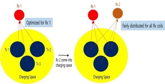
2. Description of System Architecture and Proposed Scenario

2.1. System Architecture

Figure 1 shows a WPT system with multiple Tx and Rx coils. We set up the system with three Tx coils and two Rx coils. To ignore the terms about self-inductance and capacitance at Tx and Rx coils, the proposed WPT system uses the magnetic resonance technique [22]. That is j ω L T x + 1 j ω C T x = 0 for Tx coil, and j ω L R x + 1 j ω C R x = 0 for Rx coil, where L T x ( L R x ) and C T x ( C R x ) denote the self inductance and capacitance for Tx and Rx coil, and ω means a resonant frequency in which Tx and Rx coils are tuned.

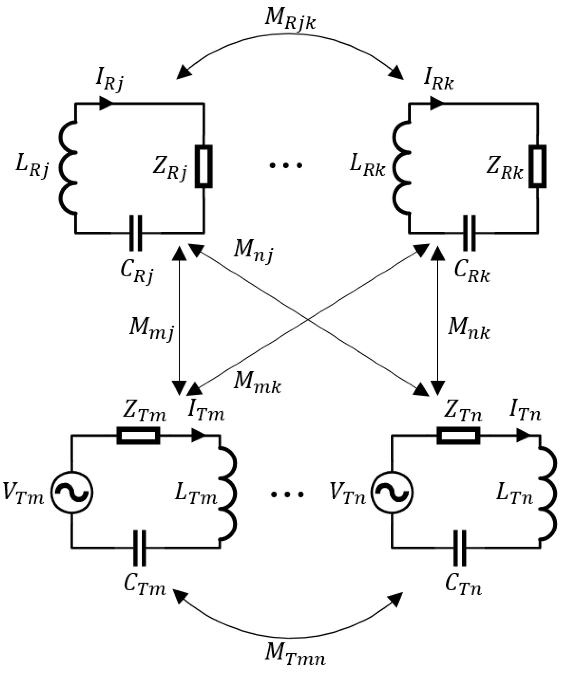
2.2. Circuit Equation

According to Kirchhoffs voltage and current law, the circuit of the WPT system can be expressed as follows:
Z R j I R j + v j j ω M R j v I R v from the other Rx coils = m j ω M m j I T m from the Tx coils
V T m = Z T m I T m + n m j ω M T m n I T n from the other Tx coils j j ω M m j I R j from the Rx coils
where V, I, and Z are the AC voltage, current, and impedance, respectively. The subscripts T and R mean the Tx and Rx. M T , M R , M mean mutual inductance between Tx–Tx, Rx–Rx, Tx–Rx respectively. To make the calculation easier, we express the above Equation (1) and (2) as matrix operation as follows:
i R = j ω Z R 1 M i T = H i T
V T = Z T + ω 2 M T Z R 1 M i T = Z T + Ψ i T
The definition of each vector and matrix is given in Table 1.

2.3. Problem Formulation and Simulation
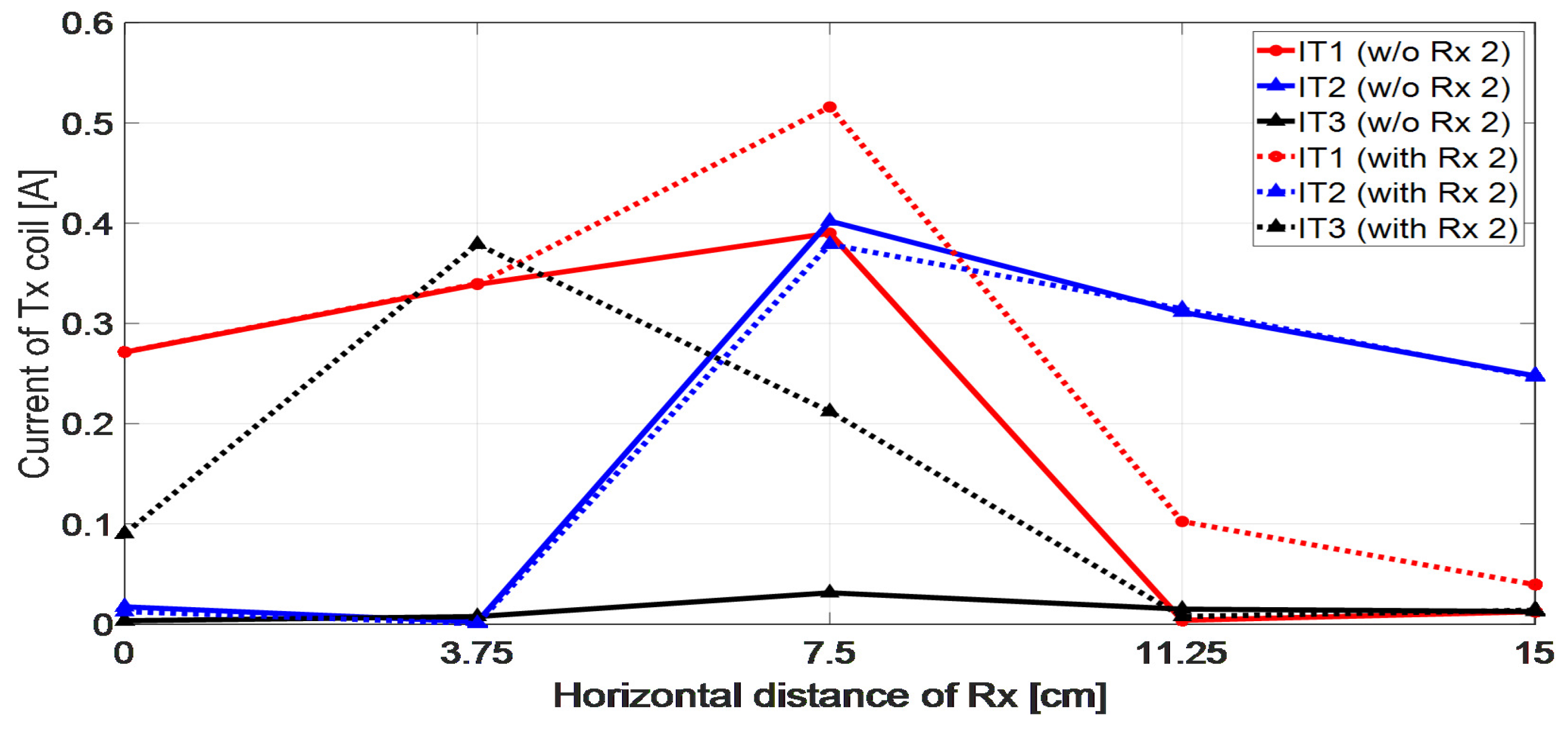
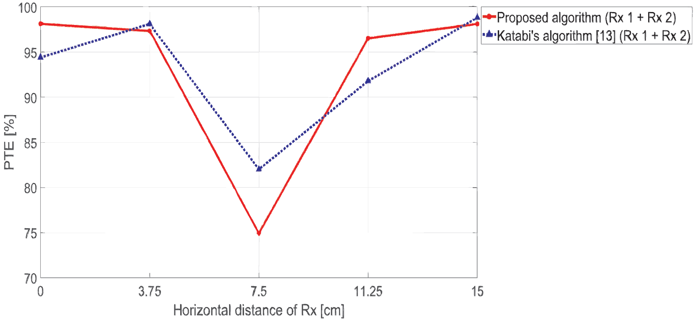
The charging scenario includes the following assumptions. First, the capacitance in each Rx coil is chosen to cancel the inductance of the Rx coil at the resonant frequency for magnetic resonance ( j ω L + 1 j ω C = 0 ) . Second, the mutual inductance between the Rx coils is very small as in the case of a system using a very small coil, so ω 2 M R i j 2 0 ( i j k ) . Third, each Rx coil comes into the charging space at different times as shown in Figure 2.
To calculate the voltages of Tx coil, Ψ is should be known. However, it is hard to estimate the H accurately without feedback from Rx coils because Z R 1 and M are included in it. In the proposed scenario, Ψ is calculated by applying n-th linearly independent voltage sets and measuring the currents of Tx coils as follows:
Ψ = v T 1 , , v T n i T 1 , , i T n 1 Z T
Because the impedance of Tx and the mutual inductance between Tx coils can be measured when the Tx coils are constructed, Z T is already known. As a result, Ψ can be estimated using only Tx coils [20]. In the case of a system with two Rx coils, Ψ ( o n l y R x 1 ) can be obtained as in Equation (5) when the first Rx coil comes into the charging space. Then, the eigenvector corresponding to the maximum eigenvalue of the ( Ψ ) can be calculated. It becomes the optimal Tx coil current vector i T for one Rx coil [20]. When the optimal solution is calculated, the Tx circuit should periodically measure the current i T flowing in the Tx coil. If a new Rx coil appears in the charging space, the calculated i T and the current flowing through the Tx coil are different, and a new solution must be calculated. When the second Rx coil comes, Ψ can be obtained for two Rx coils. Then, if ω 2 M R i j 2 0 is satisfied, Ψ ( o n l y R x 2 ) can be calculated as follows:
Ψ ( o n l y R x 2 ) Ψ Ψ ( o n l y R x 1 )
In Katabi’s algorithm [19], the eigenvector corresponding to the greatest eigenvalue of ( Ψ ) is used as the optimal solution. However, each eigenvector is orthogonal because the ( Ψ ) is positive semi-definitive matrix. Thus, Katabi’s algorithm has a problem that most power is concentrated in only one Rx coil. Therefore, in the proposed algorithm, the optimal Tx coil current is constructed as follows:
i T o p t i m a l = α 1 e ( 1 ) + α 2 e ( 2 ) = [ e ( 1 ) | e ( 2 ) ] α 1 α 2 = U α α i C
where e ( i ) means the eigenvector corresponding to the greatest eigenvalue of Ψ ( o n l y R x i ) , and α is the weight factor. With the condition ω 2 M R i j 2 0 and using Equation (3), (6) and (7), PTE can be calculated as follows:
P T E = P R P T = i T H Ψ i T i T H R T i T = i k α H U H Ψ ( o n l y R x i ) U α α H U H R T U α
where R T means diagonal matrix with the resistance of the Tx coils. Using the fact that the PTE consists of Ψ ( o n l y R x i ) , this paper proposes an algorithm that can prevent the power from being concentrated to one Rx coil. Thus, the main goal in this paper is to find the optimal α that satisfies the following:
max α min i [ k ] α H A i α α H B α A i = U H Ψ ( o n l y R x i ) U B = U H R T U
Equation (9) can be relaxed as follows [21,23]:
max α , λ i , Q i min i [ k ] { λ i } η i K A i 1 2 α λ i Q i B 1 2 α 2 2 λ i = α H A i α α H B α Q i H Q i = I n
in which η > 0 determines the weight of the penalty term added to the original problem (9). The proposed algorithm calculates the optimal solution i T of Equation (10) using the iteration method [21]. The result of the proposed algorithm is confirmed by ANSYS MAXWELL 3-D electromagnetic field simulator. The simulation model is represented in Figure 3.
For the simulation, three Tx coils with an inner diameter of 10 cm are arranged at intervals of 15 cm in the horizontal direction, and two Rx coils with an inner diameter of 5 cm are arranged at intervals of 15 cm in the horizontal direction. The distance between Tx and Rx is 5 cm. To validate the proposed algorithm at various positions on the charging space, the algorithm was applied by moving the Rx coil from the position in the left to the right in Figure 3.

3. Results

Table 2 shows the mutual inductance between the Tx coil and the Rx 1 when the position of Rx 1 is moved 5 times by 3.75 cm in the horizontal direction as shown in Figure 3. M i j represents the mutual inductance between the i-th Tx coil and the j-th Rx coil, and these values cannot be known without communication between the Tx and Rx coil. However, the Ψ ( o n l y R x 1 ) obtained as in Equation (5) can be used instead of the mutual inductance. As in the [20], the eigenvector corresponding to the maximum eigenvalue of ( Ψ ( o n l y R x 1 ) ) is calculated as shown in Table 3. Comparing Table 2 and Table 3, it can be seen that when the eigenvector of Table 3 is multiplied by a constant value, it becomes equal to the ratio of the mutual inductance of Table 2. Therefore, the optimal solution when there is only one Rx coil can be calculated using ( Ψ ( o n l y R x 1 ) ) .
After that, when Rx 2 comes into the charging space, the proposed algorithm should be applied to distribute power. To do this, the Tx side should know the existence of Rx 2. As the proposed algorithm operates without communication, it is challenging to detect Rx 2. In the proposed algorithm, Rx 2 can be detected by periodically measuring the currents of the Tx coils. When Rx 2 comes into the charging space while applying the optimal Tx coil current for Rx 1, the current in the Tx coil flows differently from the optimal solution for Rx 1. The optimal solution for Rx 1 is calculated based on Ψ ( o n l y R x 1 ) , but as Rx 2 comes into the charging space, Ψ ( o n l y R x 1 ) has been changed to Ψ in Equation (6). Therefore, if the Tx side remembers the optimal solution for Rx 1, it can detect the presence of Rx 2 by sensing the current change of the Tx coils, and apply the proposed algorithm to enable power distribution. When Rx 2 appears, the current change in the Tx coil is shown in Figure 4. As shown in the figure, there are always changes with the values among I T 1 , I T 2 , and I T 3 . Sensing such a change of the current of Tx coils, the new Rx coil can be detected without any communication.
Table 4 shows the mutual inductance between the Tx and Rx coils when Rx 2 comes into the charging space. Compared with Table 2, the values of M 11 , M 21 , and M 31 are hardly affected by the presence of Rx 2. Considering the actual charging situation, the devices that need to be charged are spaced by a certain distance from each other. For example, electric vehicles in a parking lot will be spaced apart from each other, and electronic products on charging pads will also be placed in random positions away from each other. In other words, Rx coils that are far apart have little influence on each other, so the approximation used in Equation (6) becomes valid.
Figure 5 shows how power is distributed to each Rx coil when the proposed algorithm is applied. For comparison, Katabi’s algorithm [19] is analyzed and applied to the same simulation to confirm the result. Katabi’s group in MIT proposed an algorithm that can transmit power with maximum efficiency without feedback to multiple Rx coils. Since Katabi’s algorithm does not consider power distribution, it is suitable for checking the power distribution performance of proposed algorithm. As a result, the power is properly distributed between 40∼60% to the two Rx coils as the Rx coil moves as shown in Figure 3. It can be seen that the power is well distributed among the multiple Rx coils. The result of Katabi’s algorithm (dashed line) has a very large difference in PTE for the two Rx coils, except for the 7.5 cm position. On the contrary, using the proposed algorithm, the PTE difference between the two Rx coil is relatively small with all Rx coils position. The case where the horizontal distance of the Rx coil is 7.5 cm is as shown in the Figure 6.
In this case, power is equally distributed to both Rx coils, since both Rx coils have almost the same mutual inductance with the Tx coils.
Figure 7 represents the sum of the PTE of all Rx coils when the two algorithms are applied. Compared with Katabi’s algorithm, the proposed algorithm has some loss in the sum of PTE, but it is possible to achieve a sum of PTE of more than 75%. The proposed algorithm has a higher performance compared to another reference that proposes an algorithm that considers power distribution [12], which achieves more than 60% of the sum of PTE at the same distance with our simulation (5 cm) between Tx and Rx coils.

4. Conclusions

A Tx coil control algorithm that considers the situation where multiple users request fair power transmission at the same time and there is no communication between Tx and Rx is proposed. The proposed algorithm is applied to a simulation model in which three Tx coils and two Rx coils are spaced by a distance of 5 cm. As a result of the simulation, it is confirmed that power can be distributed to each Rx coil with an efficiency of 40∼60% for any change in the position of the Rx coil. The total PTE for the two Rx coils maintained more than 75%. In many practical cases, a fair power distribution to each Rx coil is much more important than maximizing the sum of the power transmitted to all Rx coils. In our work, we compared the proposed method with the results of Katabi’s algorithm to show the performance of our algorithm for a fair power distribution without feedback. The proposed algorithm can be easily extended to more Rx coils and it presents some potentials in tackling conditions where the Rx coils have a small size or are incapable of communication with Tx coils.

Author Contributions

The present work was conducted in cooperation with all authors. J.H. and S.P. analyzed the problem and performed numerous simulations; S.-W.K., I.-K.C., S.H. and Y.B.P. contributed to the conceptualization and validation. All authors have read and agreed to the published version of the manuscript.

Funding

This research received no external funding.

Acknowledgments

This was supported by Electronics and Telecommunications Research Institute (ETRI) grant funded by the Korean government. [21ZH1140, Study on 3D communication technology for hyper-connectivity].

Conflicts of Interest

The authors declare no conflict of interest.

Nomenclature

Indexes
RRx coil indexes
TTx coil indexes
Parameters
i T i Current of i-th Tx coil
i R i Current of i-th Rx coil
v T i Voltage of i-th Tx coil
v R i Voltage of i-th Rx coil
Z T i Impedance of i-th Tx coil
Z R i Impedance of i-th Rx coil
M i j Mutual inductance between i-th Tx coil and j-th Rx coil
M T i j Mutual inductance between i-th Tx coil and j-th Tx coil
M R i j Mutual inductance between i-th Rx coil and j-th Rx coil
ω resonant frequency
e eigenvector
α weight factor

References

  1. Zhang, H.; Gao, S.P.; Ngo, T.; Wu, W.; Guo, Y.X. Wireless power transfer antenna alignment using intermodulation for two-tone powered implantable medical devices. IEEE Trans. Microw. Theory Tech. 2019, 67, 1708–1716. [Google Scholar] [CrossRef]
  2. Yan, Z.; Song, B.; Zhang, Y.; Zhang, K.; Mao, Z.; Hu, Y. A rotation-free wireless power transfer system with stable output power and efficiency for autonomous underwater vehicles. IEEE Trans. Power Electron. 2018, 34, 4005–4008. [Google Scholar] [CrossRef]
  3. Park, J.H.; Kim, J.H.; Shin, Y.J.; Park, B.J.; Kim, W.S.; Cheong, S.J.; Ahn, S.Y. Toroidal-Shaped Coils for a Wireless Power Transfer System for an Unmanned Aerial Vehicle. J. Electromagn. Eng. Sci. 2019, 19, 48–55. [Google Scholar] [CrossRef]
  4. Kim, Y.W.; Boo, S.H.; Kim, G.Y.; Kim, N.Y.; Son, L.B. Wireless Power Transfer Efficiency Formula Applicable in Near and Far Fields. J. Electromagn. Eng. Sci. 2019, 19, 239–244. [Google Scholar] [CrossRef]
  5. Lee, H.W.; Boo, S.H.; Kim, G.Y.; Lee, B.S. Optimization of Excitation Magnitudes and Phases for Maximum Efficiencies in a MISO Wireless Power Transfer System. J. Electromagn. Eng. Sci. 2020, 20, 16–22. [Google Scholar] [CrossRef] [Green Version]
  6. Kim, G.Y.; Son, L.B. Design of Wireless Power and Information Transfer Systems Considering Figure of Merit for Information. J. Electromagn. Eng. Sci. 2020, 20, 241–247. [Google Scholar] [CrossRef]
  7. Dan, H.; Chao, Y.; Xu, G.; Liu, Z.; Han, H.; Su, M.; Sun, Y. An Extremum Seeking Algorithm based on Square Wave for Three-Dimensional Wireless Power Transfer System to Achieve Maximum Power Transmission. IEEE Trans. Ind. Appl. 2021. Available online: https://ieeexplore.ieee.org/document/9496216 (accessed on 16 September 2021).
  8. Yan, Z.; Yang, B.; Liu, H.; Chen, C.; Waqas, M.; Mai, R.; He, Z. Efficiency improvement of wireless power transfer based on multitransmitter system. IEEE Trans. Power Electron. 2020, 35, 9011–9023. [Google Scholar] [CrossRef]
  9. Huh, S.; Ahn, D. Two-transmitter wireless power transfer with optimal activation and current selection of transmitters. IEEE Trans. Power Electron. 2017, 33, 4957–4967. [Google Scholar] [CrossRef]
  10. Jadidian, J.; Katabi, D. Magnetic MIMO: How to charge your phone in your pocket. In Proceedings of the 20th Annual International Conference on Mobile Computing and Networking, Maui, HI, USA, 7–11 September 2014; pp. 495–506. [Google Scholar]
  11. Cao, G.; Zhou, H.; Zhang, H.; Xu, J.; Yang, P.; Li, X.Y. Requirement-driven magnetic beamforming for mimo wireless power transfer optimization. In Proceedings of the 2018 15th Annual IEEE International Conference on Sensing, Communication, and Networking (SECON), Hong Kong, China, 11–13 June 2018; pp. 1–9. [Google Scholar]
  12. Gao, T.; Wang, X.; Jiang, L.; Hou, J.; Yang, Y. Research on power distribution in multiple-input multiple-output magnetic coupling resonance wireless power transfer system. Electr. Eng. 2021, 1–8. [Google Scholar]
  13. Qi, C.; Huang, S.; Chen, X.; Wang, P. Multi-Frequency Modulation to Achieve an Individual and Continuous Power Distribution for Simultaneous MR-WPT System with an Inverter. IEEE Trans. Power Electron. 2021, 36, 12440–12455. [Google Scholar] [CrossRef]
  14. Huang, Y.; Liu, C.; Xiao, Y.; Liu, S. Separate power allocation and control method based on multiple power channels for wireless power transfer. IEEE Trans. Power Electron. 2020, 35, 9046–9056. [Google Scholar] [CrossRef]
  15. Lee, S.B.; Kim, M.; Jang, I.G. Determination of the Optimal Resonant Condition for Multireceiver Wireless Power Transfer Systems Considering the Transfer Efficiency and Different Rated Powers with Altered Coupling Effects. IEEE J. Emerg. Sel. Top. Power Electron. 2020, 9, 2384–2393. [Google Scholar] [CrossRef]
  16. Le-Huu, H.; Seo, C. Dual-Band Free-Positioning Transmitting Coil for Multiple-Receiver Wireless Power Transfer. IEEE Access 2021, 9, 107298–107308. [Google Scholar] [CrossRef]
  17. Xie, X.; Xie, C.; Li, L. Wireless power transfer to multiple loads over a long distance with load-independent constant-current or constant-voltage output. IEEE Trans. Transp. Electrif. 2020, 6, 935–947. [Google Scholar] [CrossRef]
  18. Park, S.; Choi, W. Transmitter Current Control and Receiver Coil Selection in Magnetic MIMO Power Transfer Systems. IEEE Wirel. Commun. Lett. 2020, 9, 1782–1785. [Google Scholar] [CrossRef]
  19. Shi, L.; Kabelac, Z.; Katabi, D.; Perreault, D. Wireless power hotspot that charges all of your devices. In Proceedings of the 21st Annual International Conference on Mobile Computing and Networking, Paris, France, 7–11 September 2015; pp. 2–13. [Google Scholar]
  20. Shi, L. Orientation-Indepedent Wireless Charging of Multiple Mobile Devices at a Distance. Ph.D. Thesis, Massachusetts Institute of Technology, Cambridge, MA, USA, 2016. [Google Scholar]
  21. Gharanjik, A.; Soltanalian, M.; Shankar, M.R.B.; Ottersten, B. Grab-n-Pull: A max-min fractional quadratic programming framework with applications in signal and information processing. Signal Process. 2019, 160, 1–12. [Google Scholar] [CrossRef]
  22. Kurs, A.; Karalis, A.; Moffatt, R.; Joannopoulos, J.D.; Fisher, P.; Soljačić, M. Wireless power transfer via strongly coupled magnetic resonances. Science 2007, 317, 83–86. [Google Scholar] [CrossRef] [PubMed] [Green Version]
  23. Karipidis, E.; Sidiropoulos, N.D.; Luo, Z.Q. Quality of Service and Max-Min Fair Transmit Beamforming to Multiple Cochannel Multicast Groups. IEEE Trans. Signal Process. 2008, 56, 1268–1279. [Google Scholar] [CrossRef] [Green Version]
Figure 1. The configuration of n × k WPT system.
Energies 14 06828 g001
Figure 2. Proposed charging scenario. Rx 1 comes into the charging space first, then Rx 2 comes.
Energies 14 06828 g002
Figure 3. Simulation model using Tx coils with an inner diameter of 10 cm and Rx coils with an inner diameter of 5 cm.
Energies 14 06828 g003
Figure 4. The current change of the Tx coil when the Rx 2 comes into the charging space.
Energies 14 06828 g004
Figure 5. PTE results for each Rx coil. Proposed algorithm vs. Katabi’s algorithm.
Energies 14 06828 g005
Figure 6. Rx coil position: 7.5 cm. Both Rx coils have almost the same mutual inductance with the Tx coils.
Energies 14 06828 g006
Figure 7. The sum of PTE results for all Rx coil. Proposed algorithm vs. Katabi’s algorithm.
Energies 14 06828 g007
Table 1. The definition of vector and matrix.
TermDefinitionExplanation
i T , i R i T 1 , , i T n T Current of Tx, Rx coil
i R 1 , , i R k T
v T , v R v T 1 , , v T n T Voltage of Tx, Rx coil
v R 1 , , v R k T
Z T , Z R Z T 1 j ω M T 12 j ω M T 1 n j ω M T 21 Z T 2 j ω M T 2 n j ω M T n 1 j ω M T n 2 Z T n Impedance of Tx, Rx coil
Z R 1 j ω M R 12 j ω M R 1 k j ω M R 21 Z R 2 j ω M R 2 k j ω M R k 1 j ω M R k 2 Z R k
M M 11 M 21 M n 1 M 1 k M 2 k M n k Mutual inductance between Tx and Rx coil
M T , M R M T 11 M T 21 M T n 1 M T 1 n M T 2 n M T n n Mutual inductance between Tx(Rx) and Tx(Rx) coil
M R 11 M R 21 M R k 1 M R 1 k M R 2 k M R k k
Table 2. Simulation Results of mutual inductance when there is only Rx 1 on charging space.
Horizontally Moved 0 cm3.75 cm7.5 cm11.25 cm15 cm
M 11 [nH]2920.342345.96985.830.71−159.06
M 21 [nH]−184.61−15.451016.212550.123195.03
M 31 [nH]−35.98−52.2−78.85−121.65−161.19
Table 3. Eigenvector corresponding to maximum eigenvalue of ( Ψ ) when there is only Rx 1 on charging space.
Horizontally Moved 0 cm3.75 cm7.5 cm11.25 cm15 cm
e 0.998 0.063 0.012 1 0.007 0.022 0.695 0.717 0.056 0.012 0.999 0.048 0.05 0.998 0.05
Table 4. Simulation Results of mutual inductance when there are both Rx coils on charging space.
Horizontally Moved 0 cm3.75 cm7.5 cm11.25 cm15 cm
M 11 [nH]2920.072345.97984.51104.03−159.26
M 21 [nH]−183.41−14.771017.272374.553198.45
M 31 [nH]−36−52.24−78.84−114.82−160.78
M 12 [nH]−158.61−120.63−78.47−54.79−35.85
M 22 [nH]3198.892565.541035.4669.36−181.91
M 32 [nH]−161.7222.52969.292177.212919.35
Publisher’s Note: MDPI stays neutral with regard to jurisdictional claims in published maps and institutional affiliations.

