Article

Heat Transfer Effect on Micro Gas Turbine Performance for Solar Power Applications

Department of Mechanical Engineering and Aeronautics, University of London, Northampton Square, London EC1V 0HB, UK
*
Author to whom correspondence should be addressed.
Energies 2021, 14(20), 6745; https://doi.org/10.3390/en14206745
Submission received: 28 September 2021 / Revised: 12 October 2021 / Accepted: 13 October 2021 / Published: 16 October 2021
(This article belongs to the Collection Women in Thermal Management)

Abstract

:
This paper presents an experimentally validated computational study of heat transfer within a compact recuperated Brayton cycle microturbine. Compact microturbine designs are necessary for certain applications, such as solar dish concentrated power systems, to ensure a robust rotodynamic behaviour over the wide operating envelope. This study aims at studying the heat transfer within a 6 kWe micro gas turbine to provide a better understanding of the effect of heat transfer on its components’ performance. This paper also investigates the effect of thermal losses on the gas turbine performance as a part of a solar dish micro gas turbine system and its implications on increasing the size and the cost of such system. Steady-state conjugate heat transfer analyses were performed at different speeds and expansion ratios to include a wide range of operating conditions. The analyses were extended to examine the effects of insulating the microturbine on its thermodynamic cycle efficiency and rated power output. The results show that insulating the microturbine reduces the thermal losses from the turbine side by approximately 11% without affecting the compressor’s performance. Nonetheless, the heat losses still impose a significant impact on the microturbine performance, where these losses lead to an efficiency drop of 7.1% and a net output power drop of 6.6% at the design point conditions.

1. Introduction

Microgeneration power systems are gaining popularity as a result of increasing interest in the distributed power generation and the stricter emission standards [1]. Recuperated Brayton cycle Micro Gas Turbines (MGTs) (to be referred to in this paper as ‘microturbines’, or MGT) are reliable machines and have the flexibility to be operated using a wide range of fuels. They can also be integrated in renewable energy systems, such as solar dish microturbine systems, and combined heat and power systems, such as domestic boilers [2]. These characteristics give microturbines the potential to play a vital role in the power generation sector in the transition to zero net carbon dioxide emissions and for the longer term. Despite this, microturbines occupy a narrow place in the power generation sector globally because of their low conversion efficiency [3,4] and high capital cost. This low efficiency stems from miniaturising the turbomachinery components, which results in significantly lower aerodynamic efficiency than their larger counter parts. The aerodynamic efficiency penalty originates from the smaller blade heights, machining tolerances, larger clearance gaps to blade height ratios and the effect of operating at low Reynolds numbers. The latter results in a higher skin friction and larger heat transfer losses.
On another aspect, miniaturising the turbomachinery components requires operating at higher speeds, which leads to a close proximity between the spinning components to eliminate shaft resonant frequencies from the operating envelope [5]. More specifically, the hot turbine in such machines will be closer to the compressor, bearings and high-speed generator, which increases the risk of parts failure and leads to large power output losses due to the need for high cooling of the microturbine components [6,7,8].
Verstraete et al. [9] numerically investigated the influence of heat transferred from the turbine on the compressor performance for an assumed overhung design of an MGT. In their study, they eliminated the components of the MGT except for the impellers of the turbine and compressor. They found that the heat transferred to the compressor reduces its efficiency by around 1% compared with its adiabatic efficiency.
Park et al. [6] conducted a conjugate heat transfer analysis on a 1 kWe MGT to study the heat transfer and temperature distribution within its components. They also studied the effects of using different insulating materials on the turbine (hot side) on the temperature distribution along the MGT. They reported that using a lower conductivity insulator does not have a significant effect on the temperature distribution across the MGT body. Moreover, they found that the use of higher conductivity materials in the turbine casing was more beneficial as this leads to more heat rejection to the ambient atmosphere, leading to safer operation.
Using 1D loss correlations, Verstraete et al. [10] studied the effect of heat transfer on the performance of centrifugal compressors with impeller tip diameters ranging between 40 and 200 mm. The study revealed that the compressor loses 9% of its efficiency for 10% heat addition (ratio of heat addition to impeller’s adiabatic work). This drop in the efficiency was found to be irrelevant to the size of the impeller while it increases significantly with lowering the impeller’s rotational speed. In a more recent study, Verstraete et al. [11] examined the impact of heat transfer on a 1 kWe MGT similar to the one cited in Reference. In this study, the authors used a reduced order lumped capacitance heat transfer network method to evaluate the heat transfer within the MGT. To simplify their model, the authors excluded the generator and the recuperator from the analysis. By evaluating the discrepancy between the turbine and compressor’s power output and inputs, they found a drop of 40 W when the heat transfer is considered.
Most of the previous studies were confined to investigating the effects of heat transfer from the turbine on the compressor performance. These studies were mostly influenced by the work performed on turbocharger components, based on the assumption that turbochargers and MGTs are similar machines. However, this assumption is inadequate as it neglects the fact that MGTs are required to generate power and they include an electric machine, which needs to operate safely along the operating line, in particular for compact designs when all components are in close proximity. None of the previous studies have conducted an analysis to estimate the effect of heat losses from the turbine (hot side) on the power output of the MGT. Furthermore, most of the studies in the literature lack validation with representative experimental data. Therefore, this study is devoted to investigating for the first time the heat transfer within a compact MGT designed and built for a solar dish power system. The system has a power rating of 6 kWe and has been experimentally tested using a purpose-built test rig at City, University of London, which provides the necessary data for model validation. The analysis is performed at different operating conditions to study the heat transfer effect on the MGT at the design and off conditions. This study aims at improving the accuracy of predicting the performance and the power output of such system, which has an impact on the overall design of a solar powered microturbine system, including the sizing of the solar receiver and its cost and control strategy. This work also evaluates the effect of insulating the MGT housing on the thermal losses, in an effort to reduce the effect of heat transfer on the MGT performance.

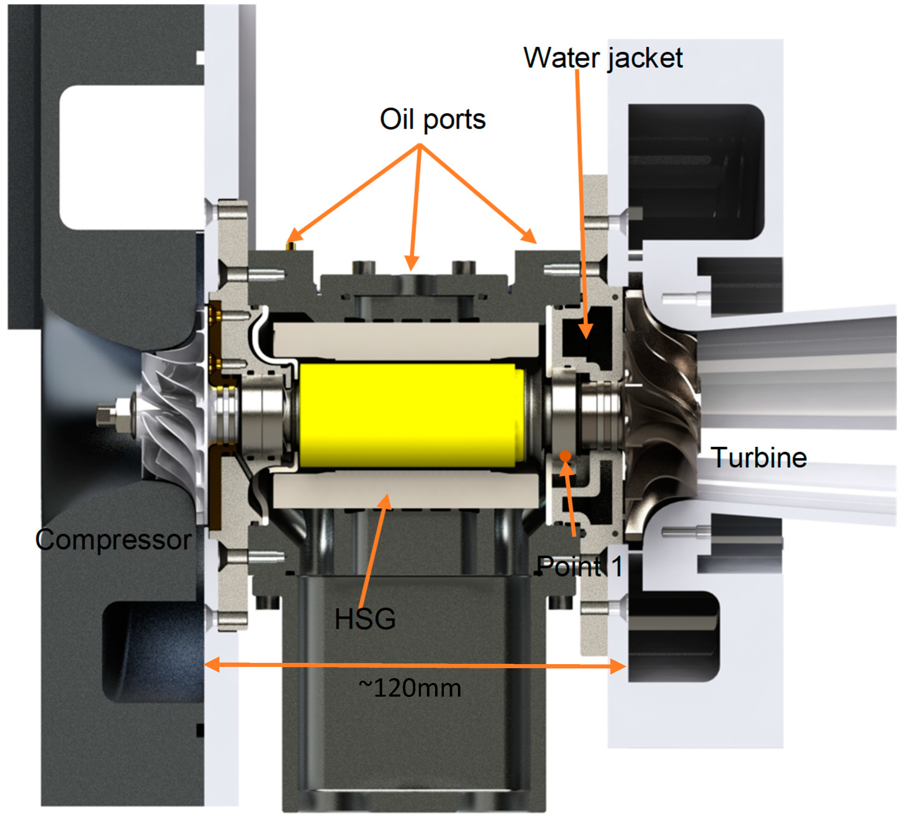
2. Microturbine under Study

Figure 1 shows a cutaway of the MGT under study. The MGT was designed and built at City, University of London, to fit a solar dish system for the “Optimised Micro Gas Turbine for Solar Power” (OMSoP) [12] project. The MGT was designed to generate 6 kWe, which requires the electrical machine to rotate at 130,000 rpm at the design point. One of the main features of concentrated solar power (CSP) systems is that they operate across a wide range of thermal power inputs due to the wide variation and fluctuations in the direct normal irradiance (DNI) of the sun. For this reason, one of the main design constraints for the MGT was the rotordynamic stability of the spinning shaft across the operating speed range (namely 100–150 krpm); in other words, the shaft should not have critical speeds within the operating window. Three different shaft-bearing arrangements (cantilevered turbine and compressor, high speed generator (HSG) between turbine and compressor and two coupled shafts arrangements) were investigated in previously published research by one of the authors [5] to determine the most suitable layout for the MGT components. Figure 2 shows the critical speed lines for each arrangement across a range of shaft bearing stiffnesses. The estimated stiffness for the ball bearings chosen for this application ranges between 30 and 40 kN/mm, depending on the preloading applied. Based on these results, the HSG between the turbine and compressor arrangement was chosen to provide the best opportunity for achieving rotordynamic stability during operation.
Nonetheless, placing the HSG between the turbine and compressor penalises performance due to the increased cooling requirements. Thus, the motivation in the current study is to evaluate the thermal losses within the MGT and study their effects on its performance in order to explore methods to reduce the impact of the compact design on thermodynamic performance.
As Figure 1 shows, the machine consists of a central body to which two flanged bearing housings are bolted that provide a mounting for the compressor and turbine volutes. The central shaft of the MGT holds both the magnetic rotor sleeve of the HSG and the two impellers. The components material and thermal conductivities are listed in Table 1.

Cooling Requirements for the MGT

At the design point, the compressor draws ambient air at 25 °C, which is then pressurised at a pressure ratio of 3. The compressed air then passes through the heat exchanger, and the solar receiver is to be heated to 800 °C before it enters the turbine. Further details of the solar dish system can be found in Reference [1]. At the design conditions, and due to the close proximity between the turbine, the bearings and the HSG (Figure 1), it is very difficult to run the MGT without cooling the bearings and the HSG. For this reason, two cooling arrangements were used. To cool the turbine side bearing, and to insulate and protect the HSG stator, a water jacket was designed to fit the back face of the turbine rotor and contain the bearing outer race to ensure efficient cooling (Figure 1). For the second cooling arrangement, oil was used to cool the HSG and to lubricate and contribute to cooling the bearings.
The central oil feed supplies the stator cooling jacket, which is formed from annular grooves cutting into the main body of the HSG casing. The other two oil parts are fed to a groove around the outer race of the bearings where what is known as H1 bearings have been specified to be used in this MGT. These have oil feed holes drilled through the raceway and allow oil to be injected into the heart of the ball/raceway contact area and thus give the maximum cooling effect. Oil from all sources is conveyed by internal passages to the collection trough fitted to the underside of the machine.

3. Numerical Study

In this study, conjugate heat transfer analyses were conducted on the whole assembly of the MGT, which will allow the evaluation of the heat transfer from the working fluid through the solid parts of the MGT to the cooling water, lubricating oil and ambient air.
The computational domain consists of fluid and solid domains. There are four fluid domains, namely the turbine flow path, cooling water, lubrication oil and the compressor flow path. The solid domain consists of all the MGT solid parts.
CFD analyses were completed using ANSYS CFX 2019.R2 utilising the Reynolds-Averaged Navier–Stokes (RANS) solver, which uses a finite volume formulation to solve the flow equations. CFX also allows to define solid regions where the conduction heat transfer equations can be solved simultaneously. Within the solid regions, the equation of energy conservation is used to calculate the heat transport due to conduction.
ANSYS workbench 2019.R2 was used to generate unstructured meshes for the fluid and solid domains. To ensure that the solution is a mesh refinement independent, a grid independence study was performed for the fluid and solid domains separately. For the fluid domains, the flow rates and the absolute velocities of the flow at the inlet and discharge were compared for five grids with different densities. Meanwhile, for the solid domain, a fixed wall temperature was applied to the turbine rotor surface and the heat flux through the compressor impeller surface were compared for the different grid. The mesh densities used for each domain are the ones that resulted in an error less than 1% in the examined values compared to the results generated by the finest grids. As a result of the grid independence study, the final mesh statistics are listed in Table 2.
The current analysis aims to evaluate the heat transfer within the MGT at the design point operating conditions. Table 3 lists the boundary conditions for all the components, which were then used to initialise the setup for the heat transfer calculations.
At the inlet sections of all the fluid domains, the Reynolds number calculation suggested the flow to be turbulent; therefore, the flow was assigned to be turbulent in the setup. The Shear Stress Transport (SST) turbulence model was used as it had previously shown a good agreement with the experimental data for radial turbines [15,16]. The analysis was repeated for three different bounding wall setups. In the first simulation, the MGT was considered to run without both cooling and heat transfer to the ambient. For this case, the MGT casing walls were set to adiabatic boundary condition and the cooling fluids were eliminated from the setup. For the second simulation, cooling was considered but the heat transfer to the surroundings was ignored by keeping MGT casing walls as adiabatic. In the last simulation, the MGT was considered to run with cooling and heat transfer to the surroundings. To calculate the heat loss to the surroundings, it was necessary to estimate the average convection heat transfer coefficient (h) for the surfaces of the MGT. As the outer surface of the MGT is in direct contact with the surrounding air, the walls lose heat to the air primarily via free convection. As shown in Figure 1, the walls of the MGT are either cylindrical or flat surfaces normal to the axis of rotation. With this arrangement, h ¯ can be calculated using Equation (1) [17] for the flat surfaces and Equation (2) [17] for the cylindrical surfaces:
h ¯ = N u ¯ f k L = [ 0.68 + 0.387 R a L 1 / 6 [ 1 + ( 0.492 P r ) 9 / 16 ] 4 / 9 ] k L
h ¯ = N u ¯ c y k D = [ 0.6 + 0.387 R a D 1 / 6 [ 1 + ( 0.559 P r ) 9 / 16 ] 8 / 27 ] k D
where N u ¯ is the average Nusselt number for both flat and cylindrical surfaces, k is the thermal conductivity of the fluid, P r is Prandtl number, L is the length of the flat surface and D is the cylinder diameter. Finally, R a is Rayleigh number, which is calculated as follows [18]:
R a = g β ( T s T ) X 3 ν α
where g is the gravitational acceleration, β is the thermal expansion coefficient of the fluid, X is the surface characteristic length (for the flat plate is the length L and for the cylinder is the diameter D), ν is the kinematic viscosity, α is the thermal diffusivity, and T s and T are the surface and the surrounding air temperatures, respectively. All thermo-physical properties used in Equations (1)–(3) are determined at the film temperature T f = ( T s T ) / 2 . With the ambient air temperature known, the only remaining parameter required to calculate h ¯ is the surface temperature of the MGT. The surface temperature of the MGT components was estimated from the thermal images taken during testing the machine, which will be discussed in Section 5.

4. Test Rig

A test rig has been developed to experimentally evaluate the performance of the MGT at different design conditions and to estimate the heat transfer losses occurring during operation. The test results in this work will be used to evaluate the heat transfer coefficient at the surface of the MGT and to validate the numerical methodology used in this paper. Future publications will show a detailed analysis of the MGT experimental investigations. The test rig and the MGT are illustrated in Figure 3. To perform this test, the MGT was run using the electric drive up to a certain speed at which the compressor can generate sufficient flow to run the electric heater safely. An electric heater with a maximum capacity of 40 kWe was used to raise the temperature of air before entering the turbine. A heater was chosen instead of a combustor to mimic the solar receiver behaviour as it runs on air and no fuel combustion products were added to the working fluid. The Supervisory Control and Data Acquisitions (SCADA) system based on LabVIEW software and National Instruments™ hardware were used in the test rig. The output power of the heater was controlled using a voltage signal generator in the SCADA system, which provides control over the turbine inlet temperature (TIT). Whilst the drive was used to run the MGT, the generated power from the turbine was used to aid the drive by providing part of the centrifugal compressor load.

Temperature Measurements

As stated earlier, this experiment aims to evaluate the heat transfer coefficient at the MGT external walls and to provide experimental data for model validation. This requires knowledge of the temperature distribution along those surfaces. For this purpose, a thermal imaging camera was considered as a suitable option; a Flir A325 Infrared (IR) camera was used in the test. The camera is equipped with an 18 mm focal length lens, and it has a spatial resolution of 320 × 240 pixels and a thermal sensitivity of 0.05 °C.
As the MGT components were machined out of aluminium and stainless steel, which have a very low emissivity, it was necessary to coat the MGT with a high emissivity thermal spray to enable the camera to correctly detect the temperature of the surfaces. The spray emissivity was evaluated using a similar method used by Tanda et al. [16]. The results of the IR camera were calibrated using the in-situ calibration procedure reported by Martiny et al. [17]. This method relies on the comparison between the thermal images and a reference temperature, which should be taken simultaneously at a steady-state condition. In this test, the reference temperatures were taken using pre-calibrated thermocouples attached at six different positions on the MGT surface. The measurements from the thermocouples and the camera were logged to a computer synchronously. As we calibrated the thermal images with the thermocouple measurements, which have an uncertainty of ±1 °C, the thermal image measurements were considered to be of the same range of uncertainty as the thermocouples, despite their higher accuracy.
For the purpose of validating the numerical method, the temperature of the cooling fluids was measured at the inlet and outlet manifolds. Moreover, the metal temperature, 1.5 mm away from the turbine bearing outer race, was measured (see point 1 in Figure 1).
The initial calculations for the cooling fluid temperatures and bearing casing temperature revealed that the maximum temperature is below 100 °C, and therefore, all the temperature measurements were made using T-type thermocouples. This type offers the highest accuracy among the common thermocouples and its response time is small. The accuracy of the thermocouples used in the test is ±1 °C. The cooling fluid temperatures were taken at the inlet and discharge manifold where a bare wire thermocouple was inserted at the supply and discharge ports. For the metal temperature around the turbine bearing, another bare wire thermocouple was inserted into the hole drilled at point 1.
All the measurements were logged to a computer through a National Instruments (NI) 9211 Data Acquisition (DAQ) module. This module has four channels and an integrated circuit for cold junction compensation. This module has a high accuracy in reading the temperature (±0.02 °C) when it operates at room temperature (23 °C). All the thermocouples were calibrated using a dry block calibrator, the calibration data were implemented in the software and the final reading was displayed to monitor the measurements during the test. The test interface was designed to give the flexibility to save the measured data to an excel sheet at any desired point.

5. Validation of the Numerical Model

The first step in validating the numerical method was to evaluate the heat transfer coefficients on the outer walls of the MGT that are used in the CFD boundary conditions. Figure 4a shows the thermal image acquired after running the MGT close to the design point turbine inlet temperature for approximately 30 min (for the test conditions refer to Table 4).
Based on this temperature distribution, Equations (1) and (2) were used to calculate the walls’ convection heat transfer coefficients (see Table 5). With this known, the CFD analyses have been performed to validate the numerical method at the same operating conditions listed in Table 4. The results from the experiment and the CFD (Table 6) show a good match where the CFD values fall within or close to the uncertainty range of the measurements. This gives confidence in using the proposed method to conduct the thermal analyses in this study.

6. Results and Discussion

Having validated the numerical model, the heat transfer analysis was applied to a range of operating scenarios of interest.

6.1. MGT with Different Cooling Arrangement

As mentioned in Section 3, the heat transfer analysis was conducted for three different MGT cooling arrangements. Figure 5a–c shows the temperature contours along a cross-section (refer to Figure 5d) through the MGT body for the considered cases. In the first case (Figure 5a), the cooling water and oil have been eliminated from the analysis. The temperature distribution in this case shows the extent of the effect of heat transferred from the turbine to the rest of the MGT parts.
With this design, the power loss is not of any importance as the maximum allowable operating temperature for the MGT parts are exceeded by a huge margin. For example, the maximum allowable bearing temperature is 393 K, while with no cooling, the temperature reaches 600 K. Similarly, the maximum operating temperature of the HSG is 423 K; therefore, reaching a temperature close to 600 K will cause demagnetisation of its permanent magnet, which means electric generator failure. The high temperatures of the MGT components resulting from the absence of cooling makes this design impractical. Thus, to realise a practical (working) design for the MGT with the current architecture, adding cooling to the HSG and the bearings is essential.
With cooling in place, the possibility of insulating the MGT to prevent further energy loss to the ambient was explored. Figure 5b,c shows the temperature distribution for the cases of insulated and non-insulated MGTs, respectively. In both cases, the addition of the cooling water jacket and the cooling oil prevents overheating of the bearings and the HSG components. It is also noticeable that adding the insulation does not cause a significant rise in temperature of the MGT components compared to the case where no insulation was added. On the other hand, adding insulation preserves 400 W of thermal power from being dissipated to the surroundings. To understand why the shaft temperature was not affected, the heat fluxes through all the solid faces of the turbine housing have been calculated. The results show that the heat flux through the turbine rotor is the lowest and forms a negligible part of the total heat flux. Most of the heat is transferred through the back face of the turbine housing and is dissipated by the cooling water and oil. The lower heat flux through the rotor is due to the high thermal resistance of the rotor shaft compared to the low thermal resistance for the turbine casing. Similar observations have been previously reported by Verstraete et al. [9]. This explains why adding the insulation did not cause a noticeable rise in the shaft temperature, which also means that the heat transferred to the compressor wheel will not be affected when insulation is applied. To confirm this, the difference in heat flux passing through the compressor impeller was compared for the insulated and non-insulated cases and this was found to be almost constant.
Despite the amount of thermal power saved by using insulation, a large amount of this power is still dissipated by the cooling fluids. Therefore, to correctly evaluate the performance of the MGT turbomachinery, heat transfer should be properly accounted for in performance calculations. The effects of thermal losses on the performance of the microturbine are discussed in the next section.

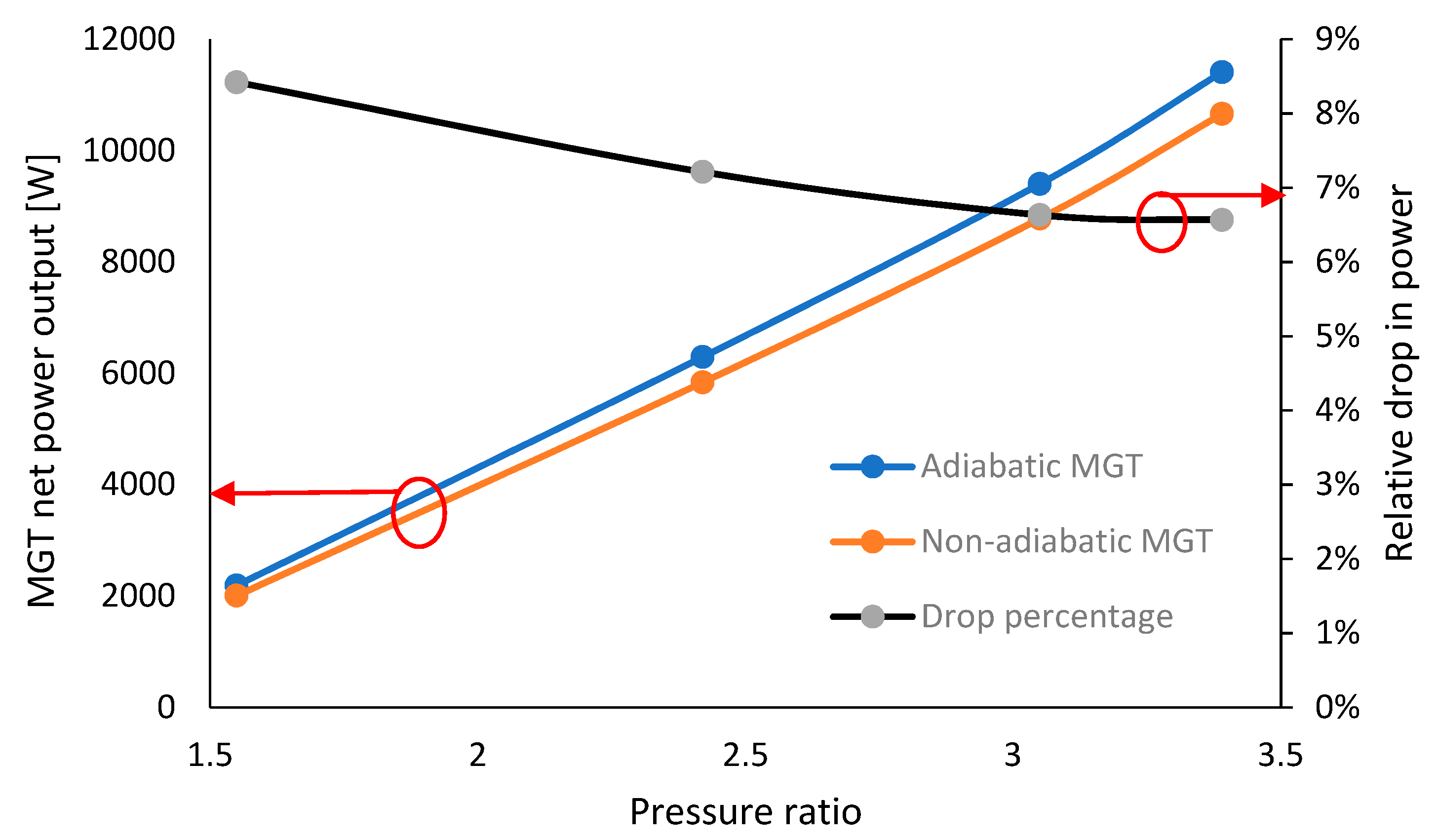
6.2. Gas Turbine Performance

To explain the effect of heat transfer in the compressor and turbine on the thermodynamic cycle performance, a simple Brayton cycle is used. Figure 6a shows the temperature–entropy (T-S) diagram for a simple cycle gas turbine operating adiabatically. Actual compression and expansion processes compared to the ideal (isentropic processes) are shown. The compressor operates between the states 1 and 2a and the turbine between 3 and 4a. With this configuration, the efficiency of the gas turbine cycle (1-2a-3-4a-1) is given by Equation (4):
η g t _ a d = specific   work   output   specific   input   power = ( T 3 T 4 a ) ( T 2 a T 1 ) ( T 3 T 2 a )
Obviously, the gas turbine efficiency is strongly affected by the state of working fluid at the turbine and compressor’s inlet and discharge, respectively. On the other hand, if heat transfer is taken into account within the MGT, the thermal losses will lead to a change in the boundary conditions for both the turbine and compressor, as shown in Figure 6b. The actual path for the gas turbine is 1-2a-2h-3-3h-4h-1, and the efficiency of the MGT is given by:
η g t _ d i a = specific   work   output   specific   input   power = ( T 3 h T 4 h ) ( T 2 a T 1 ) ( T 3 T 2 h )
where the subscript h indicates the state after considering heat loss.
Different studies have been conducted to investigate how heat transfer affects turbine and compressor performance in different applications. To determine the compressor and turbine efficiencies, researchers used different approaches based on the heat transfer mechanism within the bodies of the machines. One of the most common methods is to correct the isentropic efficiency definition by modifying the actual power term by taking the amount of heat loss into account. This method is based on two main assumptions. Firstly, the compression and expansion both occur adiabatically. Secondly, the heat gain or loss happens before and after the compression and expansion, respectively [19]. In the current study, this method has been used to calculate the non-adiabatic cycle conditions.
Prior to evaluating the non-adiabatic performance of the gas turbine, the thermal analysis has been performed at different operating conditions to evaluate the thermal losses along the operating line of the engine. As a single shaft engine, the operating line is defined along the best efficiency line on the compressor map, which normally matches that of the turbine. The full maps for the turbine and compressor were previously published by the authors [1]. Table 7 summarises the chosen operating conditions of the MGT at the chosen operating points.
The results of the analysis (refer to Table 8) reveals that most of the heat loss occurs in the volutes for both the turbine and compressor. On the compressor side, the temperature of the air at the impeller eye is atmospheric, which is lower than that of the impeller surface. This results in heat transfer from the impeller to the air. As the compressed air moves towards the impeller discharge, its temperature rises and exceeds the impeller surface temperature. Therefore, the heat flux changes its direction.
This explains the low heat transfer rate through the impeller. On the other hand, the air temperature within the volute is higher than that of the casing surface, and therefore the air rejects heat to the cooled generator casing. This heat rejection from the compressor casing occurs in turbochargers when operated at high rotational speeds [19]. For the turbine side, the results are discussed in Section 6.1.
With the heat transfer results obtained, it is now possible to evaluate the non-adiabatic MGT cycle parameters and therefore the efficiency and power output. By referring to Figure 6b, it is evident that the compressor and the turbine will be running adiabatically between the points 1–2a and 3h–4h as all the heat transfer happens at the volute where no shaft work occurs. Therefore, the adiabatic maps can be used to evaluate the fluid conditions at 2a and 4h. The temperatures at point 2h and 4h can be evaluated by imposing the temperature drop that results from heat loss in the volutes from the adiabatic temperatures at the points 2a and 3.
Figure 7 and Figure 8 present the MGT efficiency and net power output for adiabatic and non-adiabatic conditions, respectively. It is clear that the thermal losses have a significant impact on the MGT performance, where the efficiency drops by 7.1% and the output power drops by 6.6% at the design point conditions. This drop would have a significant impact on solar powered gas turbines, as this drop has to be compensated by increasing the solar thermal input to the cycle to achieve the same power output; in reality, this means a larger solar receiver would be required.
For the current 6 kWe solar dish system, the increment in the dish area due to thermal losses will be 5.3%, which means increasing the cost of the dish by 6.5%. This results in a larger land occupancy and higher price for the system as the dish contributes to two-thirds of the system’s cost [20]. Moreover, the results indicate higher losses when moving further from the design point. For solar powered gas turbines, this causes more complications since a solar MGT system will not always operate at the design point due to variations in the solar irradiance.

7. Conclusions

This paper presents the results of a thermal analysis for a 6 kWe micro gas turbine. The analysis firstly investigated the feasibility of insulating the MGT casing. The results showed that at the design point, insulating the engine casing could save up to 400 W of thermal energy from being dissipated to the surroundings without affecting the compressor’s performance.
By evaluating the heat flux through the different parts of the turbine, it was revealed that most of the thermal losses occur within the volute while the amount of heat lost through the rotor is negligible. This implies that the heat loss does not affect the expansion through the rotor, but instead it shifts the turbine operating point to a lower temperature, which results in a reduced power output.
In a similar manner, the heat flux through the compressor impeller is found to be negligible, while most of the rejected heat from the compressed air occurs after the fluid leaves the impeller through the volute walls. This means the heat losses within the compressor do not affect the compression work needed, instead they affect the amount of heat needed to raise the air temperature to reach the desired turbine inlet temperature.
The MGT efficiency and net power output for adiabatic and non-adiabatic conditions have been compared. The results have shown that at the design point, heat losses within the MGT lead to a 7.1% relative drop in efficiency and a 6.6% drop in the output power. These values indicate the significance of heat transfer losses on the MGT performance. In the case where the MGT serves as the power unit in a solar system, this drop has to be compensated by increasing the solar thermal input to the cycle to achieve the same power output. The required increase in the dish area has been estimated to be 5.3%, which corresponds to increasing the cost of the dish by 6.5%.

Author Contributions

Conceptualisation, M.A.K.; data curation, M.A.K.; formal analysis, M.A.K.; funding acquisition, J.A.-Z. and A.I.S.; investigation, M.A.K.; methodology, M.A.K.; project administration, Mohsen Ghavami, J.A.-Z. and A.I.S.; resources, A.I.S.; software, M.A.K. and M.G.; supervision, J.A.-Z. and A.I.S.; validation, M.A.K.; writing—original draft, M.A.K.; writing—review and editing, M.A.K., M.G., J.A.-Z. and A.I.S. All authors have read and agreed to the published version of the manuscript.

Funding

This research was part of the SolGATS (Concentrated Solar Power Micro Gas Turbine with Thermal Energy Storage (https://researchcentres.city.ac.uk/thermo-fluids/solgats. Accessed on 12 October 2021) project which is funded by Innovate UK and Ministry of Science and Technology of the People’s Republic of China, grant number 102879.

Institutional Review Board Statement

Not applicable.

Informed Consent Statement

Not applicable.

Conflicts of Interest

The authors declare that they have no known competing financial interests or personal relationships that could have appeared to influence the work reported in this paper.

Nomenclature

Letters
h ¯ Average heat transfer coefficient (W/m2.K)
k Thermal conductivity (W/m.K)
N u ¯ Average Nusselt number
P r Prandtl number
L Length of flat surface (m)
D Diameter of the cylinder (m)
R a Rayleigh number
T Temperature (K)
g Gravitational acceleration (m/s2)
β Thermal expansion coefficient (1/K)
X Surface characteristic length
Greeks
ν Kinematic viscosity (m2/s)
α Thermal diffusivity (m2/s)
Subscripts
1Compressor inlet
2Compressor discharge
3Turbine inlet
4Turbine discharge
a, adAdiabatic state
h, diaNon-adiabatic state
s Surface
Free stream fluid
f Film
g t Gas turbine
Abbreviations
CFDComputational Fluid Dynamics
CSPConcentrated Solar Power
DNIDirect Normal Irradiance
HSGHigh Speed Generator
MGTMicro Gas Turbine
RANSReynolds-Average Navier–Stokes
SSTShear Stress Transport

References

  1. Khader, M. Development of a Micro Gas Turbine for Concentrated Solar Power Applications. Ph.D. Thesis, Department of Mechanical Engineering and Aeronautics, University of London, London, UK, 2017. [Google Scholar]
  2. Pilavachi, P.A. Mini- and Micro-gas Turbines for Combined Heat and Power. Appl. Therm. Eng. 2002, 22, 2003–2014. [Google Scholar] [CrossRef]
  3. Rodgers, C. Some Effects of Size on the Performances of Small Gas Turbines. In Proceedings of the ASME TurboExpo, Atlanta, GA, USA, 16–19 June 2003. [Google Scholar]
  4. Hamilton, S.L. The Handbook of Microturbine Generators; Pennwell: Tulsa, OK, USA, 2003. [Google Scholar]
  5. Arroyo, A.; Mclorn, M.; Sayma, A.; Fabian, M.; White, M. Rotor-Dynamics of Different Shaft Configurations for A 6 kW Micro Gas Turbine for Concentrated Solar Power. In Proceedings of the ASME Turbo Expo, Seoul, Korea, 13–17 June 2016. [Google Scholar]
  6. Park, J.S.; Park, S.; Kim, K.M.; Choi, B.S.; Cho, H.H. Effect of the Thermal Insulation on Generator and Micro Gas Turbine System. Energy 2013, 59, 581–589. [Google Scholar] [CrossRef]
  7. van den Braembussche, R.A. Micro Gas Turbines—A Short Survey of Design Problems. NATO Publ. 2012, 3, 18. [Google Scholar]
  8. Gong, Y.; Sirakov, B.T.; Epsten, A.H.; Tan, C.S. Aerothermodynamics of Micro-Turbomachinery. In Proceedings of the ASME Turbo Expo, Vienna, Austria, 14–17 June 2004. [Google Scholar]
  9. Verstraete, T.; Alsalihi, Z.; van den Braembussche, R.A. Numerical Study of the Heat Transfer in Micro Gas Turbines. J. Turbomach. 2007, 129, 835–841. [Google Scholar] [CrossRef]
  10. Verstraete, D.; Hewakuruppu, Y. Impact of Heat Transfer on Centrifugal Compressors of Micro Turbines. In Proceedings of the ASME International Mechanical Engineering Congress & Exposition, Houston, TX, USA, 9–15 November 2012. [Google Scholar]
  11. Verstraete, D.; Bowkett, C. Impact of Heat Transfer on the Performance of Micro Gas Turbines. Appl. Energy 2015, 138, 445–449. [Google Scholar] [CrossRef]
  12. Sayma, I. Optimised Microturbine Solar Power system, City, Univerisity of London, 2013. Available online: https://omsop.serverdata.net/Pages/Home.aspx (accessed on 18 February 2021).
  13. Lampros, K. Electron Beam Melting of Titanium Aluminides: Process Development and Material Properties Optimisation; University of Sheffield: Sheffield, UK, 2017. [Google Scholar]
  14. A. Materials. Alloys Specifications. AZO Meterials. Available online: https://www.azom.com/properties.aspx?ArticleID=863 (accessed on 4 August 2020).
  15. Tanda, G.; Marelli, S.; Marmorato, G.; Capobianco, M. An Experimental Investigation of Internal Heat Transfer in an Automotive Turbocharger Compressor. Appl. Energy 2017, 531–539. [Google Scholar] [CrossRef]
  16. Martiny, M.; Schiele, R.; Gritsch, M.; Schulz, A.; Witting, S. In Situ Calibration for Quantitative Infrared Thermography. Quant. Infrared Thermogr. 1996. [Google Scholar] [CrossRef]
  17. Romagnolia; Manivannana, A.; Rajoob, S.; Chiongb, M.S.; Feneleyc, A.; Pesiridisc, A.; Martinez-Botasd, R.F. A Review of Heat Transfer in Turbochargers. Renew. Sustain. Energy Rev. 2017, 79, 1442–1460. [Google Scholar] [CrossRef] [Green Version]
  18. Incropera, F.P. Fundamentals of Heat and Mass Transfer; John Wiley: Hoboken, NJ, USA, 2011. [Google Scholar]
  19. Shaaban, S.; Seume, J. Impact of Turbocharger Non-Adiabatic Operation on Engine Volumetric Efficiency and Turbo Lag. Int. J. Rotating Mach. 2011, 2012, 11. [Google Scholar] [CrossRef] [Green Version]
  20. Ghavami, M. Cycle Analysis and Optimisation of Micro Gas Turbines for Concentrated Solar Power; City, University of London: London, UK, 2017. [Google Scholar]
Figure 1. Cutaway of City University of London’s 6 kWe MGT showing its components and indicating the distance between the turbine and compressor.
Energies 14 06745 g001
Figure 2. Critical speed maps for three different MGT layouts: (a) cantilever turbine and compressor, (b) two coupled shafts for turbocomponents and HSG (c) HSG between turbine and compressor.
Energies 14 06745 g002
Figure 3. (a) MGT test rig installed at City, University of London, and (b) the gas turbine used in the test with the main components pointed out.
Energies 14 06745 g003
Figure 4. (a) Thermal image of MGT during test used to calculate the convective heat transfer coefficients of the wall sections. (b) MGT after coating.
Energies 14 06745 g004
Figure 5. (ac) MGT temperature profiles for the cases: no cooling used, with cooling oil and water used but no heat transfer to ambient allowed and with cooling oil and water and heat transfer to ambient allowed (d) Measurement section.
Energies 14 06745 g005
Figure 6. T-S diagram for gas turbine operating on an (a) adiabatic cycle and (b) non-adiabatic cycle.
Energies 14 06745 g006
Figure 7. MGT adiabatic and non-adiabatic efficiency at different operating conditions and the relative drop in efficiency when considering heat transfer in the calculations.
Energies 14 06745 g007
Figure 8. MGT net power output at different operating conditions considering an adiabatic and non-adiabatic run and the relative drop in power when considering heat transfer in the calculations.
Energies 14 06745 g008
Table 1. MGT components material properties.
ComponentMaterialThermal Conductivity (w/m·k)
Turbine rotorGamma-Titanium Aluminide17 [13]
Turbine volute and Water jacket casingStainless steel 31614 [14]
HSG casingAluminum alloy 6063-T6209 [14]
HSG Rotor and statorSteel/copper~100
Compressor impeller and Compressor VoluteAluminum alloy 6063-T6209 [14]
Table 2. Mesh statistics for the MGT components.
ComponentNodes
Turbine fluid domain609019
Compressor fluid domain653915
Cooling water fluid domain153500
Cooling oil fluid domain98000
MGT solid domain906770
Table 3. MGT components’ boundary conditions.
Boundary ConditionValueComponent
Inlet total pressure2.92 (bar)Turbine
Inlet total Temperature1073 (K)
Outlet static pressure1 (bar)
Mass flow rate0.09 (kg/s)
Inlet total pressure1.01325 (bar)Compressor
Inlet total Temperature295 (K)
Outlet total pressure3.04 (bar)
Mass flow rate0.09 (kg/s)
Inlet total Temperature283 (K)Cooling water
Outlet static pressure1.01325 (atm)
Mass flow rate0.0417 (kg/s)
Inlet total pressure2 (bar)Cooling oil
Inlet total Temperature293 (K)
Outlet static pressure1.01325 (bar)
Mass flow rate0.0176 (kg/s)
Table 4. MGT components’ boundary conditions.
Boundary ConditionValueComponent
Inlet total pressure1.33 (bar)Turbine
Inlet total Temperature1023 (K)
Outlet static pressure1 (bar)
Mass flow rate0.03 (kg/s)
Inlet total pressure1.01325 (bar)Compressor
Inlet total Temperature295 (K)
Outlet total pressure1.332 (bar)
Mass flow rate0.03 (kg/s)
Inlet total Temperature283.5 (K)Cooling water
Outlet static pressure1.01325 (atm)
Mass flow rate0.0417 (kg/s)
Inlet total pressure2 (bar)Cooling oil
Inlet total Temperature309 (K)
Outlet static pressure1.01325 (atm)
Mass flow rate0.0176 (kg/s)
Table 5. MGT external wall free convection heat transfer coefficient calculations.
Turbine VoluteCompressor VoluteHSG Casing
Average heat transfer coefficient ( h ¯ ) (W/m2·K)7.84.75.3
Table 6. Comparison between the CFD and test rig results at the validation point.
Temp. Measurement LocationTest Rig Results (±1 K)CFD Results (K)% Difference between CFD and Test
Cooling oil discharge316.25315.450.25%
Cooling water discharge288.35289.650.45%
Point 1 (1.5 mm from bearing outer race)297.91299.950.68%
Table 7. Heat loss in the turbine and compressor.
Flow Rate (kg/s)Pressure RatioRotational Speed (krpm)T1 (K)T3 (K)
0.10453.391402951073
0.08953.05130
0.0682.42115
0.041.5580
Table 8. Heat loss in the turbine and compressor (all units in Watt).
Turbine Heat LossTurbine Volute Loss Turbine Rotor Loss Compressor Loss Compressor Volute Loss Compressor Impeller Loss
3475.9341560.9−338.6−3390.4
3128.65306761.65−287.4−2880.6
2794273361−229.2−2311.8
2171.4210962.4−69.5−71.62.1
Publisher’s Note: MDPI stays neutral with regard to jurisdictional claims in published maps and institutional affiliations.

