
Details on the Hydrothermal Characteristics within a Solar-Channel Heat-Exchanger Provided with Staggered T-Shaped Baffles

 , , , ,
Abstract
:1. Introduction
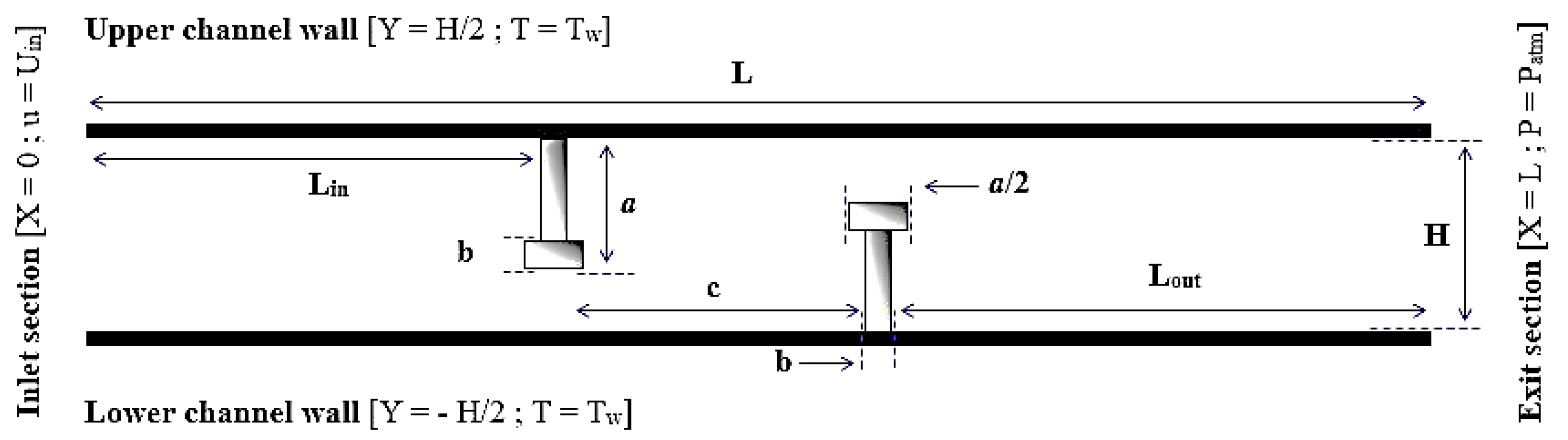
2. Problem under Inspection
3. Mathematical Tools
3.1. Considerations
3.2. Turbulence Model
3.2.1. k-Equation
3.2.2. ε-Equation
3.3. Governing Parameters
3.3.1. Reynolds Number
3.3.2. Friction Factor
3.3.3. Heat Transfer
3.4. Experimental Correlations
3.4.1. Petukhov Correlation
3.4.2. Dittus–Boelter Correlation
3.5. Thermal Enhancement Factor (TEF)
4. Computational Details
4.1. Numerical Methods
4.2. Mesh Dependency Tests
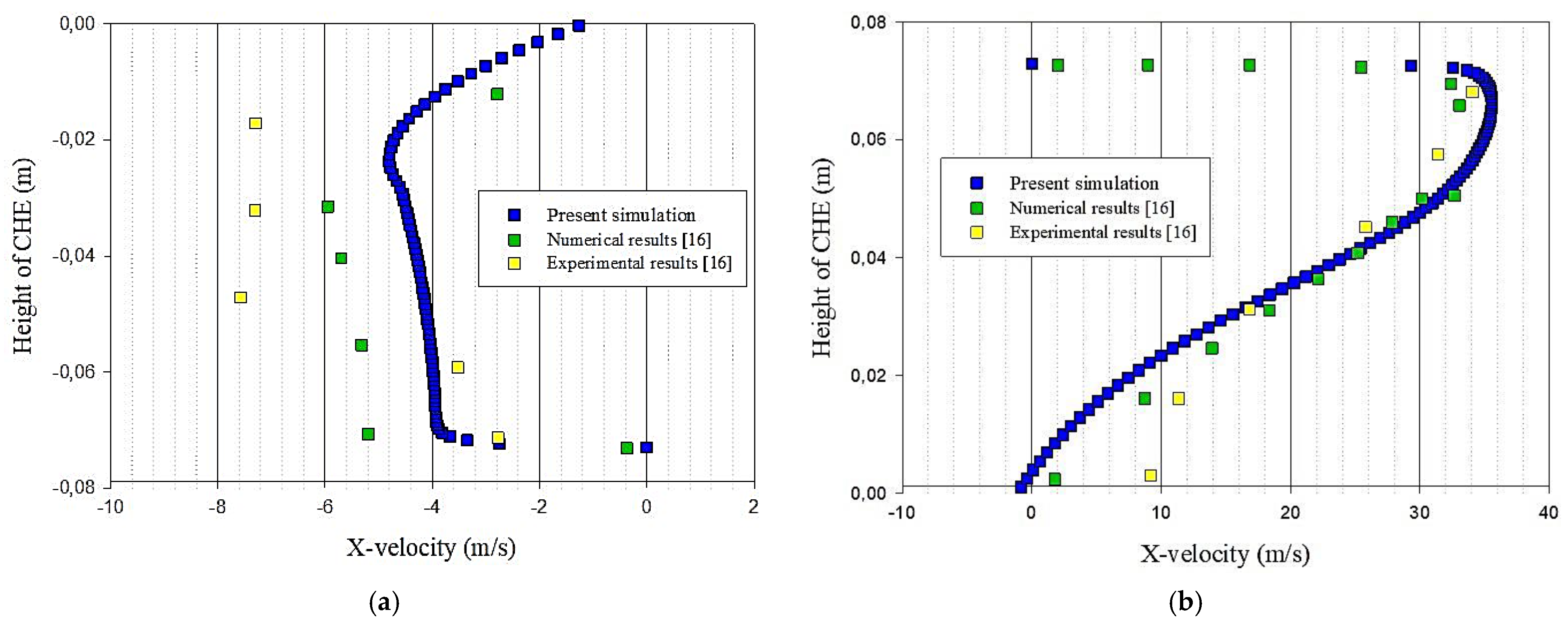
4.3. Validation of the Model
5. Findings and Analysis
6. Conclusions
- (1)
- At the VG level, the wall effect is augmented due to the reduction of the passage area of flows, which is estimated here to be 55%, resulting thus in a considerable resistance to the movement of fluid particles.
- (2)
- The 2nd T-shaped VG generates a considerable movement of the fluid particles in the vertical direction, which increases the reattachment length of the separated flows.
- (3)
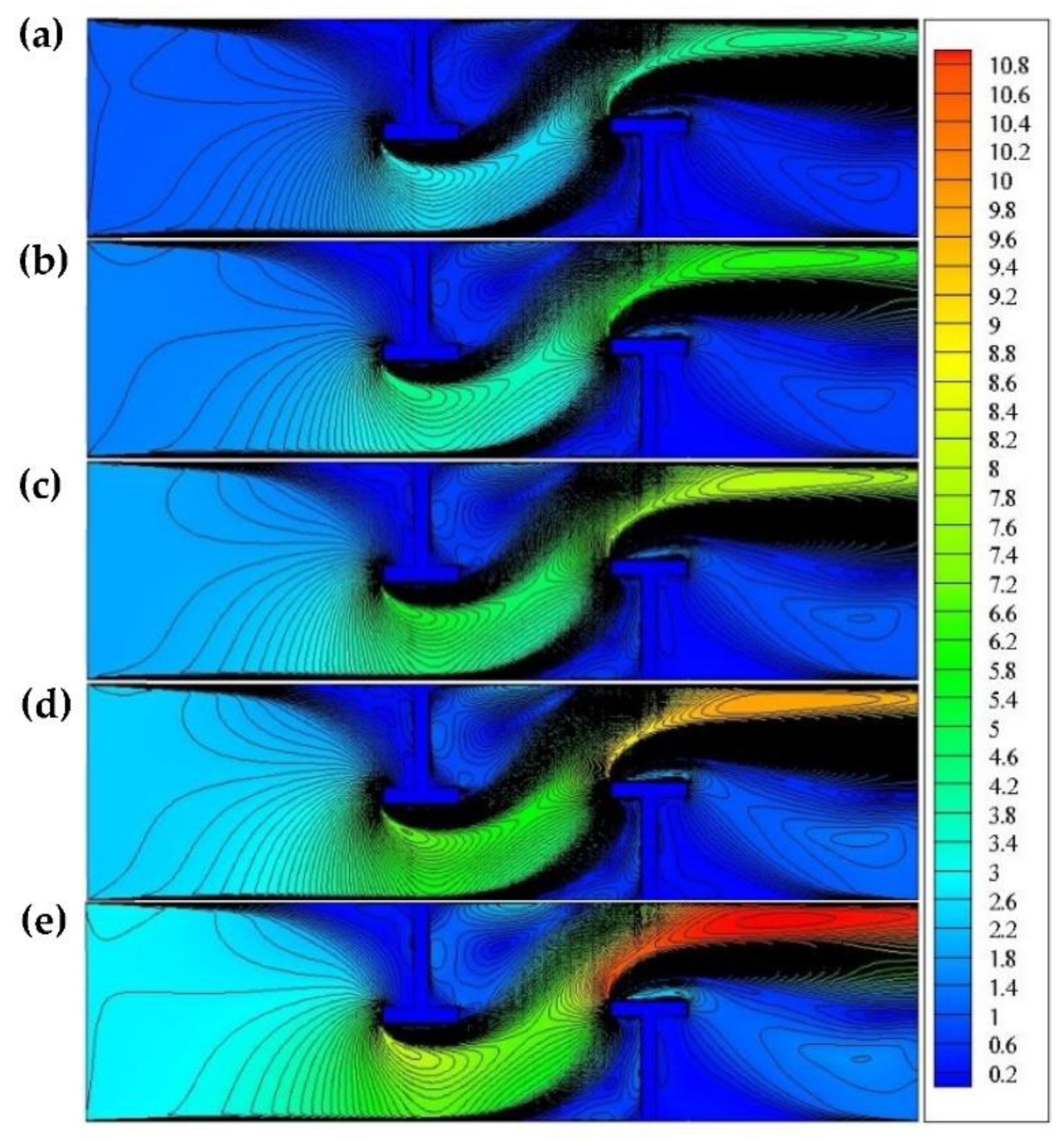
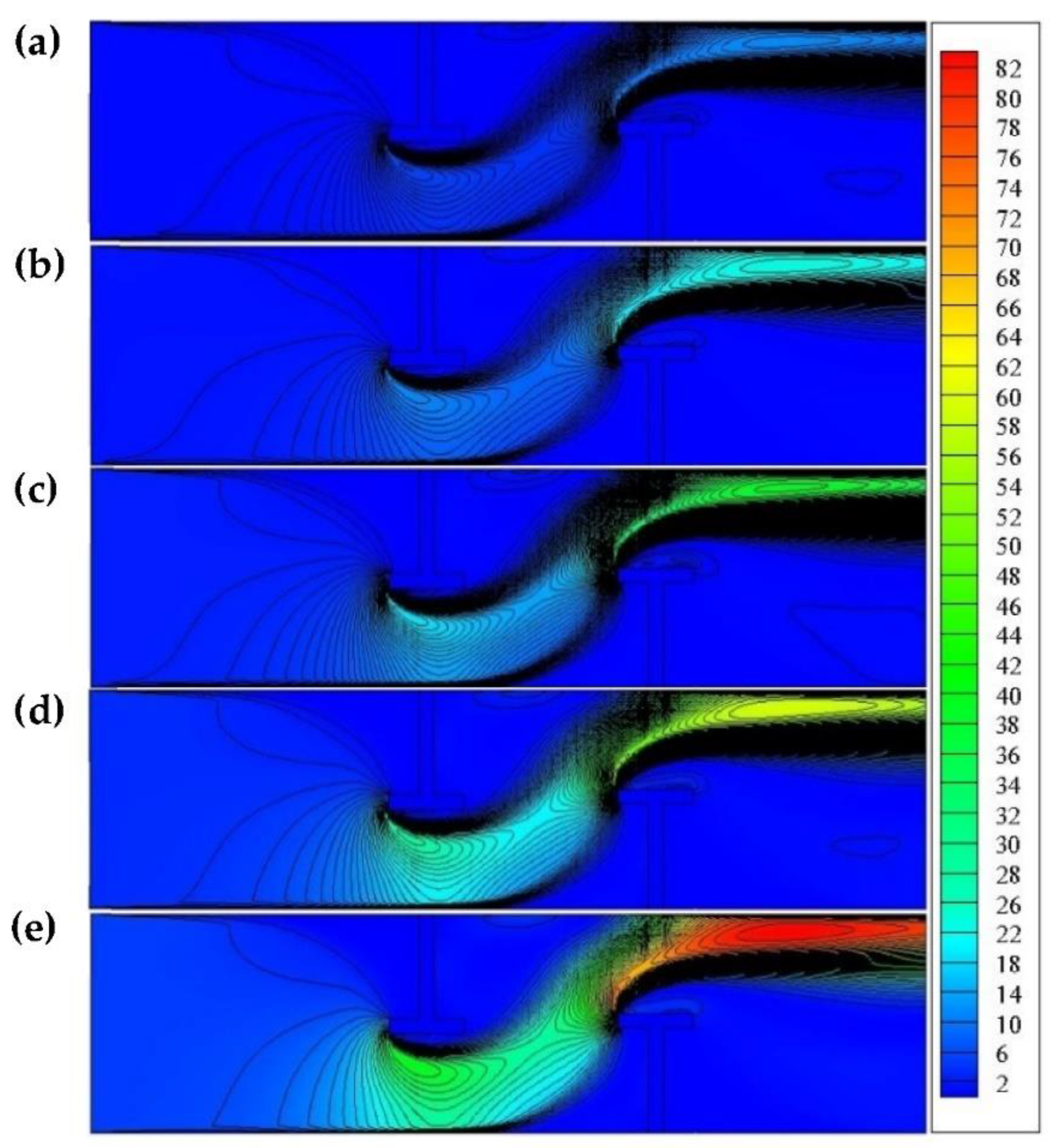
- The thermal distribution is highly dependent on the flow structures within the CHE. Since the fluid agitation yields an enhanced mixing, it allows thus an excellent heat transfer. The heat transfer process starts just after the 1st VG. Furthermore, and compared with the unbaffled CHE, high amounts of the temperature are observed in the recirculation cells that are formed in the area downstream of the T-VGs. In this recirculation region, a poor heat transfer process is occurring.
- (4)
- The most considerable rates of thermal transfer are obtained with high Re, which results from the intensified mixing of fluid particles through the formation of recirculation cells and the interaction with the walls of the T-baffles and the channel.
- (5)
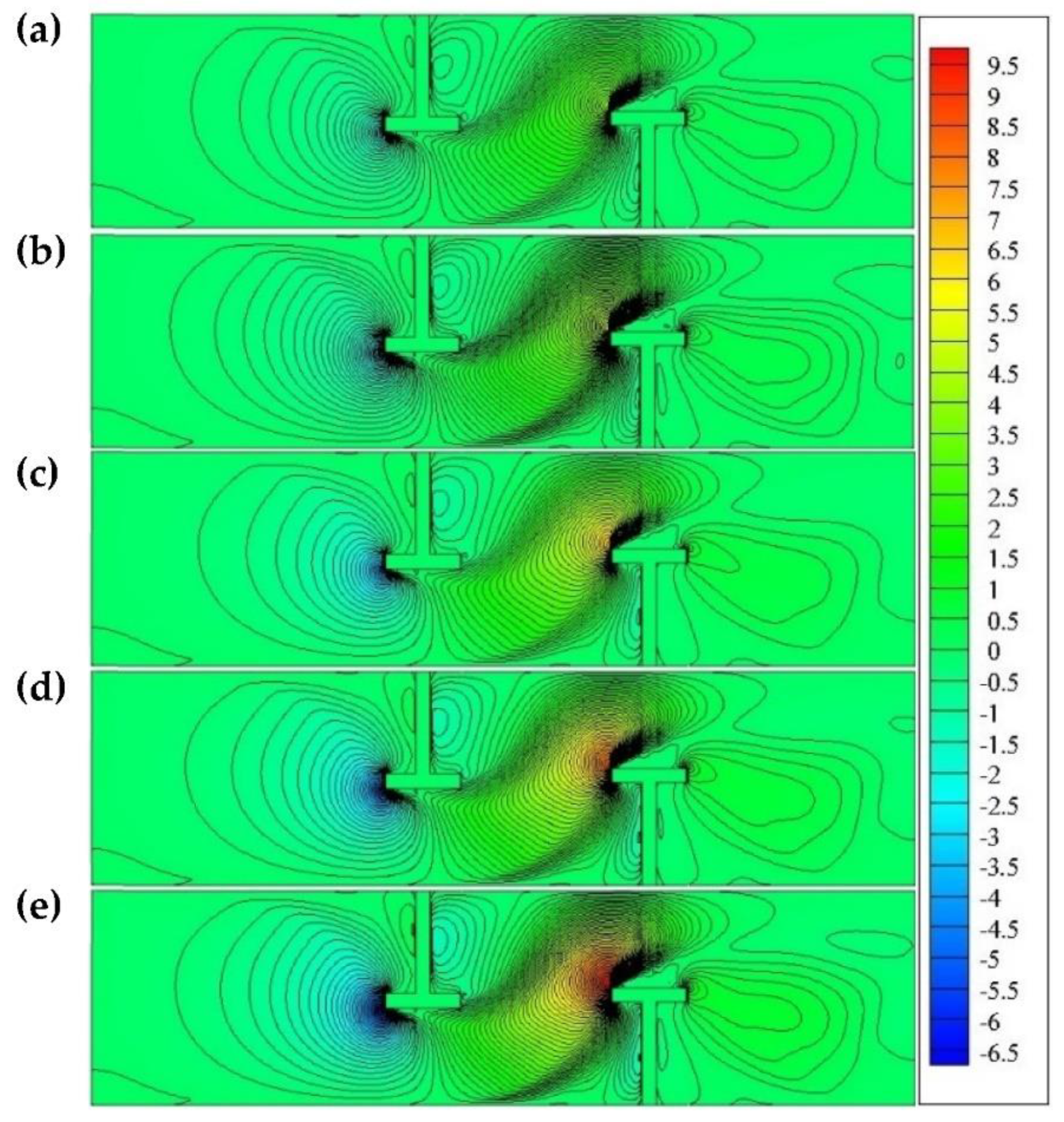
- The T-baffles with intense flow rates yield negative turbulent speeds and intensify the fluid agitation, which improves the thermal exchange rates.
- (6)
- The highest amounts of Cf/f0 are shown in the unbaffled zone closed to the channel exit. These significant amounts correspond to the considerable pressure losses that are yielded by the abrupt change in the airflows at the level of the 2nd baffle.
- (7)
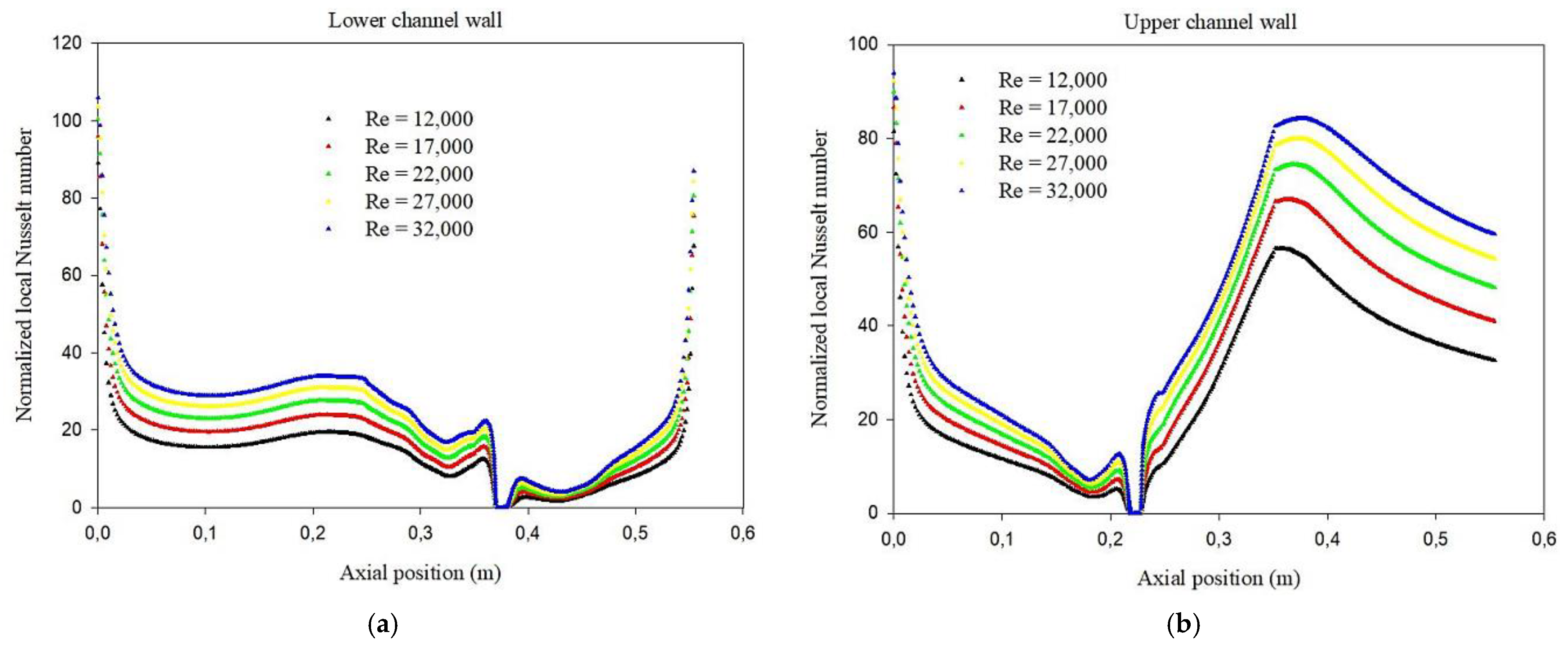
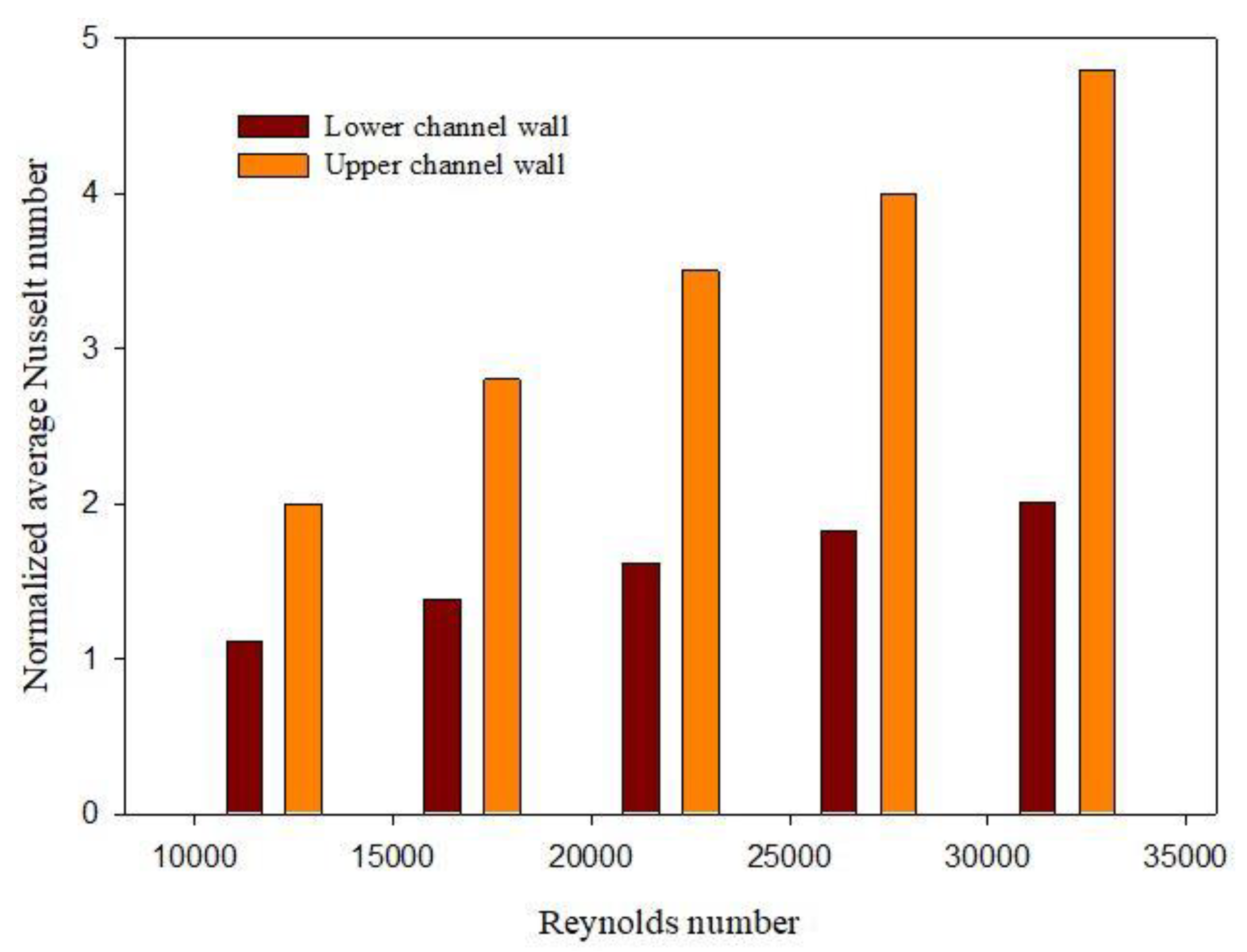
- The most significant values of Nu and f are observed on the upper surface of the exchanger, due to the highest temperature and speed gradients in this area.
- (8)
- The achieved performance has been compared to that of several previous studies. Among all the VGs reported and investigated, the best improvement factor is obtained with the new tested obstacles, i.e., T-shaped VGs.
Author Contributions
Funding
Institutional Review Board Statement
Informed Consent Statement
Data Availability Statement
Acknowledgments
Conflicts of Interest
References
- Zhang, L.; Cui, X.; Lu, Z.; Miao, C.Y.; Jui, L.W. A novel spiral channel with the growing waviness on the sidewalls for compact high-efficiency heat exchanger. Appl. Energy 2021, 299, 117332. [Google Scholar] [CrossRef]
- Xu, Y.; Cui, G.; Han, X.; Xiao, Y.; Zhang, G. Optimization route arrangement: New concept to achieve high efficiency and quality in heat exchanger network synthesis. Int. J. Heat Mass Transf. 2021, 178, 121622. [Google Scholar] [CrossRef]
- Ahmad, H.; Sakhri, N.; Menni, Y.; Omri, M.; Ameur, H. Experimental study of the efficiency of earth-to-air heat exchangers: Effect of the presence of external fans. Case Stud. Therm. Eng. 2021, 28, 101461. [Google Scholar] [CrossRef]
- Menni, Y.; Azzi, A.; Chamkha, A.J. Enhancement of convective heat transfer in smooth air channels with wall-mounted obstacles in the flow path. J. Therm. Anal. Calorim. 2019, 135, 1951–1976. [Google Scholar] [CrossRef]
- Awais, M.; Bhuiyan, A.A. Heat transfer enhancement using different types of vortex generators (VGs): A review on experimental and numerical activities. Therm. Sci. Eng. Prog. 2018, 5, 524–545. [Google Scholar] [CrossRef]
- Menni, Y.; Azzi, A.; Chamkha, A. A review of solar energy collectors: Models and applications. J. Appl. Comput. Mech. 2018, 4, 375–401. [Google Scholar]
- Chen, D.; Zhang, R.; Cao, X.; Chen, L.; Fan, X. Numerical investigation on performance improvement of latent heat exchanger with sextant helical baffles. Int. J. Heat Mass Transf. 2021, 178, 121606. [Google Scholar] [CrossRef]
- Cao, X.; Zhang, R.; Chen, D.; Chen, L.; Du, T.; Yu, H. Performance investigation and multi-objective optimization of helical baffle heat exchangers based on thermodynamic and economic analyses. Int. J. Heat Mass Transf. 2021, 176, 121489. [Google Scholar] [CrossRef]
- Salhi, J.E.; Zarrouk, T.; Salhi, N. Numerical study of the thermo-energy of a tubular heat exchanger with longitudinal baffles. Mater. Today Proc. 2021, 45, 7306–7313. [Google Scholar] [CrossRef]
- Patankar, S.V.; Liu, C.H.; Sparrow, E.M. Fully developed flow and heat transfer in ducts having streamwise-periodic variations of cross-sectional area. ASME J. Heat Transf. 1977, 99, 180–186. [Google Scholar] [CrossRef]
- Kelkar, K.M.; Patankar, S.V. Numerical prediction of flow and heat transfer in a parallel plate channel with staggered fins. ASME J. Heat Transf. 1987, 109, 25–30. [Google Scholar] [CrossRef]
- Bazdidi-Tehrani, F.; Naderi-Abadi, M. Numerical Analysis of Laminar Heat Transfer in Entrance Region of a Horizontal Channel with Transverse fins. Int. Commun. Heat Mass Transf. 2004, 31, 211–220. [Google Scholar] [CrossRef]
- Tsay, Y.L.; Chang, T.S.; Cheng, J.C. Heat transfer enhancement of backward-facing step flow in a channel by using baffle installed on the channel wall. Acta Mech. 2005, 174, 63–76. [Google Scholar] [CrossRef]
- Pirouz, M.M.; Farhadi, M.; Sedighi, K.; Nemati, H.; Fattahi, E. Lattice Boltzmann simulation of conjugate heat transfer in a rectangular channel with wall-mounted obstacles. Sci. Iran. 2011, 8, 213–221. [Google Scholar] [CrossRef] [Green Version]
- Siddiqui, M.H.K. Heat transfer augmentation in a heat exchanger tube using a baffle. Int. J. Heat Fluid Flow 2007, 28, 318–328. [Google Scholar]
- Demartini, L.C.; Vielmo, H.A.; Möller, S.V. Numeric and experimental analysis of the turbulent flow through a channel with baffle plates. J. Braz. Soc. Mech. Sci. Eng. 2004, 26, 153–159. [Google Scholar] [CrossRef] [Green Version]
- Gajusingh, S.T.; Shaikh, N.; Siddiqui, K. Influence of a rectangular baffle on the downstream flow structure. Exp. Therm. Fluid Sci. 2010, 34, 590–602. [Google Scholar] [CrossRef]
- Sakhri, N.; Draoui, B.; Menni, Y. Experimental study of earth to air heat exchanger performance in arid region. First step: In-situ measurement of ground vertical temperature profile for different depths. J. Adv. Res. Fluid Mech. Therm. Sci. 2019, 56, 183–194. [Google Scholar]
- Sakhri, N.; Moussaoui, A.; Menni, Y.; Sadeghzadeh, M.; Ahmadi, M.H. New passive thermal comfort system using three renewable energies: Wind catcher, solar chimney and earth to air heat exchanger integrated to real-scale test room in arid region (experimental study). Int. J. Energy Res. 2021, 45, 2177–2194. [Google Scholar] [CrossRef]
- Sakhri, N.; Menni, Y.; Chamkha, A.J. Heating capacity of an earth to air heat exchanger in arid regions—Experimental investigation. J. Appl. Comput. Mech. 2021. [Google Scholar] [CrossRef]
- Chamkha, A.J.; Menni, Y. Hydrogen flow over a detached v-shaped rib in a rectangular channel. Math. Model. Eng. Probl. 2020, 7, 178–186. [Google Scholar] [CrossRef]
- Boursas, A.; Salmi, M.; Lorenzini, G.; Ahmad, H.; Menni, Y.; Fridja, D. Enhanced heat transfer by oil/multi-walled carbon nano-tubes nanofluid. Ann. Chim.-Sci. Matériaux 2021, 45, 93–103. [Google Scholar] [CrossRef]
- Chekchek, B.; Salmi, M.; Boursas, A.; Lorenzini, G.; Ahmad, H.; Menni, Y.; Ameur, H.; Merrah, M.; Fridja, D. Experimental study of the efficiency of a solar water heater construction from recycled plastic bottles. Int. J. Des. Nat. Ecodynamics 2021, 16, 121–126. [Google Scholar] [CrossRef]
- Hadidi, N.; Rebhi, R.; Bennacer, R.; Menni, Y.; Ameur, H.; Lorenzini, G.; Gepreel, K.A.; Ahmad, H. Thermosolutal natural convection across an inclined square enclosure partially filled with a porous medium. Results Phys. 2021, 21, 103821. [Google Scholar] [CrossRef]
- Menni, Y.; Ameur, H.; Yao, S.W.; Amraoui, M.A.; Inc, M.; Lorenzini, G.; Ahmad, H. Computational fluid dynamic simulations and heat transfer characteristic comparisons of various arc-baffled channels. Open Phys. 2021, 19, 51–60. [Google Scholar] [CrossRef]
- Salmi, M.; Boursas, A.; Mederreg, D.; Lorenzini, G.; Ahmad, H.; Menni, Y.; Ameur, H.; Maoudj, R. Improved heat transfer in w-baffled air-heat exchangers with upper-inlet and lower-exit. Math. Model. Eng. Probl. 2021, 8, 1–9. [Google Scholar] [CrossRef]
- Dutta, P.; Hossain, A. Internal cooling augmentation in rectangular channel using two inclined baffles. Int. J. Heat Fluid Flow 2005, 26, 223–232. [Google Scholar] [CrossRef]
- Sahel, D.; Ameur, H.; Benzeguir, R.; Kamla, Y. Enhancement of heat transfer in a rectangular channel with perforated baffles. Appl. Therm. Eng. 2016, 101, 156–164. [Google Scholar] [CrossRef]
- Yang, Y.T.; Hwang, C.Z. Calculation of turbulent flow and heat transfer in a porous-baffled channel. Int. J. Heat Mass Transf. 2003, 46, 771–780. [Google Scholar] [CrossRef]
- Yilmaz, M. The effect of inlet flow baffles on heat transfer. Int. Commun. Heat Mass Transf. 2003, 30, 1169–1178. [Google Scholar] [CrossRef]
- Guerroudj, N.; Kahalerras, H. Mixed convection in a channel provided with heated porous blocks of various shapes. Energy Convers. Manag. 2010, 51, 505–517. [Google Scholar] [CrossRef]
- Sripattanapipat, S.; Promvonge, P. Numerical analysis of laminar heat transfer in a channel with diamond-shaped baffles. Int. Commun. Heat Mass Transf. 2009, 36, 32–38. [Google Scholar] [CrossRef]
- Zhang, J.F.; He, Y.L.; Tao, W.Q. 3D numerical simulation on shell-and-tube heat exchangers with middle-overlapped helical baffles and continuous baffles—Part I: Numerical model and results of whole heat exchanger with middle-overlapped helical baffles. Int. J. Heat Mass Transf. 2009, 52, 5371–5380. [Google Scholar] [CrossRef]
- Nanan, K.; Thianpong, C.; Pimsarn, M.; Chuwattanakul, V.; Eiamsaard, S. Flow and thermal mechanisms in a heat exchanger tube inserted with twisted cross-baffle turbulators. Appl. Therm. Eng. 2017, 114, 130–147. [Google Scholar] [CrossRef]
- Bekele, A.; Mishra, M.; Dutta, S. Effects of delta-shaped obstacles on the thermal performance of solar air heater. Adv. Mech. Eng. 2011, 3, 103502. [Google Scholar] [CrossRef] [Green Version]
- Zhou, G.; Ye, Q. Experimental investigations of thermal and flow characteristics of curved trapezoidal winglet type vortex generators. Appl. Therm. Eng. 2012, 37, 241–248. [Google Scholar] [CrossRef]
- Menni, Y.; Chamkha, A.J.; Zidani, C.; Benyoucef, B. Study of air flow around flat and arc-shaped baffles in shell-and-tube heat exchangers. Math. Model. Eng. Probl. 2019, 6, 77–84. [Google Scholar] [CrossRef]
- Dong, C.; Zhou, X.F.; Dong, R.; Zheng, Y.Q.; Chen, Y.P.; Hu, G.L.; Xu, Y.S.; Zhang, Z.G.; Guo, W.W. An analysis of performance on trisection helical baffles heat exchangers with diverse inclination angles and baffle structures. Chem. Eng. Res. Des. 2017, 121, 421–430. [Google Scholar] [CrossRef]
- Skullong, S.; Thianpong, C.; Jayranaiwachira, N.; Promvonge, P. Experimental and numerical heat transfer investigation in turbulent square-duct flow through oblique horseshoe baffles. Chem. Eng. Process. Process. Intensif. 2016, 99, 58–71. [Google Scholar] [CrossRef]
- Bopche, S.B.; Tandale, M.S. Experimental investigations on heat transfer and frictional characteristics of a turbulator roughened solar air heater duct. Int. J. Heat Mass Transf. 2009, 52, 2834–2848. [Google Scholar] [CrossRef]
- Menni, Y.; Chamkha, A.J.; Zidani, C.; Benyoucef, B. Baffle orientation and geometry effects on turbulent heat transfer of a constant property incompressible fluid flow inside a rectangular channel. Int. J. Numer. Methods Heat Fluid Flow 2020, 30, 3027–3052. [Google Scholar] [CrossRef]
- Menni, Y.; Azzi, A.; Chamkha, A.J.; Harmand, S. Effect of wall-mounted V-baffle position in a turbulent flow through a channel: Analysis of best configuration for optimal heat transfer. Int. J. Numer. Methods Heat Fluid Flow 2019, 29, 3908–3937. [Google Scholar] [CrossRef]
- Chamoli, S.; Thakur, N.S. Correlations for solar air heater duct with V-shaped perforated baffles as roughness elements on absorber plate. Int. J. Sustain. Energy 2016, 35, 1–20. [Google Scholar] [CrossRef]
- Jedsadaratanachai, W.; Boonloi, A. Effects of blockage ratio and pitch ratio on thermal performance in a square channel with 30° double V-baffles. Case Stud. Therm. Eng. 2014, 4, 118–128. [Google Scholar] [CrossRef] [Green Version]
- Kumar, A.; Bhagoria, J.L.; Sarviya, R.M. Heat transfer and friction correlations for artificially roughened solar air heater duct with discrete W-shaped ribs. Energy Convers. Manag. 2009, 50, 2106–2117. [Google Scholar] [CrossRef]
- Sriromreun, P.; Thianpong, C.; Promvonge, P. Experimental and numerical study on heat transfer enhancement in a channel with Z-shaped baffles. Int. Commun. Heat Mass Transf. 2012, 39, 945–952. [Google Scholar] [CrossRef]
- Petukhov, B.S. Heat transfer and friction in turbulent pipe flow with variable physical properties. Adv. Heat Transf. 1970, 6, 503–564. [Google Scholar]
- Dittus, F.W.; Boelter, L.M.K. Heat transfer in automobile radiators of the tubular type. Int. Commun. Heat Mass Transf. 1985, 12, 3–22. [Google Scholar] [CrossRef]
- Patankar, S.V. Numerical Heat Transfer and Fluid Flow; McGraw-Hill: New York, NY, USA, 1980. [Google Scholar]
- Leonard, B.P.; Mokhtari, S. Ultra-Sharp Nonoscillatory Convection Schemes for High-Speed Steady Multidimensional Flow. NASA TM 1-2568; NASA Lewis Research Center: Cleveland, OH, USA, 1990. [Google Scholar]
- Menni, Y.; Azzi, A.; Chamkha, A.J. Modeling and analysis of solar air channels with attachments of different shapes. Int. J. Numer. Methods Heat Fluid Flow 2019, 29, 1815–1845. [Google Scholar] [CrossRef]
- Menni, Y.; Azzi, A. Design and performance evaluation of air solar channels with diverse baffle structures. Comput. Therm. Sci. 2018, 10, 225–249. [Google Scholar] [CrossRef]


| Mesh | 95 × 35 | 120 × 45 | 145 × 55 | 170 × 65 | 195 × 75 | 220 × 85 | 245 × 95 | 370 × 1145 (reference) |
| Nu | 210.56 | 212.128 | 214.592 | 218.624 | 219.52 | 222.096 | 223.216 | 224 |
Publisher’s Note: MDPI stays neutral with regard to jurisdictional claims in published maps and institutional affiliations. |
© 2021 by the authors. Licensee MDPI, Basel, Switzerland. This article is an open access article distributed under the terms and conditions of the Creative Commons Attribution (CC BY) license (https://creativecommons.org/licenses/by/4.0/).
Share and Cite
Medjahed, D.M.; Ameur, H.; Rebhi, R.; Inc, M.; Ahmad, H.; Menni, Y.; Lorenzini, G.; Bayones, F.S.; Aldhabani, M. Details on the Hydrothermal Characteristics within a Solar-Channel Heat-Exchanger Provided with Staggered T-Shaped Baffles. Energies 2021, 14, 6698. https://doi.org/10.3390/en14206698
Medjahed DM, Ameur H, Rebhi R, Inc M, Ahmad H, Menni Y, Lorenzini G, Bayones FS, Aldhabani M. Details on the Hydrothermal Characteristics within a Solar-Channel Heat-Exchanger Provided with Staggered T-Shaped Baffles. Energies. 2021; 14(20):6698. https://doi.org/10.3390/en14206698
Chicago/Turabian StyleMedjahed, Driss Meddah, Houari Ameur, Redha Rebhi, Mustafa Inc, Hijaz Ahmad, Younes Menni, Giulio Lorenzini, Fatimah S. Bayones, and Musaad Aldhabani. 2021. "Details on the Hydrothermal Characteristics within a Solar-Channel Heat-Exchanger Provided with Staggered T-Shaped Baffles" Energies 14, no. 20: 6698. https://doi.org/10.3390/en14206698