Article

Investigation of the Performances of a Diesel Engine Operating on Blended and Emulsified Biofuels from Rapeseed Oil

by
Vladimir Anatolyevich Markov
1,
Bowen Sa
1,*,
Sergey Nikolaevich Devyanin
2,
Anatoly Anatolyevich Zherdev
1,
Pablo Ramon Vallejo Maldonado
3,
Sergey Anatolyevich Zykov
2,
Aleksandr Dmitrievich Denisov
4 and
Hewage Chithral Ambawatte
5
1
Power Engineering Faculty, Bauman Moscow State Technical University, 105005 Moscow, Russia
2
Department of Tractors and Automobiles, Moscow Timiryazev Agricultural Academy, Russian State Agrarian University, 127550 Moscow, Russia
3
Department of Mechanical and Instrumental Engineering, Academy of Engineering, Peoples’ Friendship University of Russia, 117198 Moscow, Russia
4
Department of Mechanical Engineering and Computer-Aided Design Systems, Kolomna Institute (Branch), Moscow Polytechnic University, 107023 Moscow, Russia
5
Department of Mechanical and Manufacturing Engineering, Faculty of Engineering, University of Ruhuna, Galle 80000, Sri Lanka
*
Author to whom correspondence should be addressed.
Energies 2021, 14(20), 6661; https://doi.org/10.3390/en14206661
Submission received: 20 September 2021 / Revised: 6 October 2021 / Accepted: 10 October 2021 / Published: 14 October 2021
(This article belongs to the Special Issue Advanced Engine Technologies and Fuels)

Abstract

:
The article discusses the possibility of using blended biofuels from rapeseed oil (RO) as fuel for a diesel engine. RO blended diesel fuel (DF) and emulsified multicomponent biofuels have been investigated. Fuel physicochemical properties have been analyzed. Experimental tests of a diesel engine D-245 in the operating conditions of the external characteristic curve and the 13-mode test cycle have been conducted to investigate the effect of these fuels on engine performances. CFD simulations of the nozzle inner flow were performed for DF and ethanol-emulsified RO. The possibility of a significant improvement in brake thermal efficiency of the engine has been noted. The efficiency of using blended biofuels from RO as a motor fuel for diesel engines has been evaluated based on the experimental test results. It was shown that in comparison with the presence of RO in emulsified multicomponent biofuel, the presence of water has a more significant effect on NOx emission reduction. The content of RO and the content of water in the investigated emulsified fuels have a comparable influence on exhaust smoke reduction. Nozzle inner flow simulations show that the emulsification of RO changes its flow behaviors and cavitation regime.

1. Introduction

Given the growing problem of global warming and increasingly stringent emissions regulations, a number of measures must be taken to reduce emissions of carbon dioxide (CO2) and emissions of pollutant substances. For thermal engine systems, these can be achieved by enhancing engine thermal efficiency and using renewable carbon-free fuels and carbon-neutral fuels. The use of renewable fuels also solves the gradual depletion of fossil fuel reserves and the rise in prices for oil and oil products. Under these conditions, using renewable fuels in transport, agriculture, and other sectors of the economy becomes necessary and economically justified [1,2,3]. Renewable fuels are fuels obtained from renewable energy resources of plant origin, the raw material reserves of which are practically unlimited [4,5]. These fuels include synthetic biofuels obtained from plant mass [6,7], bioalcohol fuels [8,9], fuels produced from vegetable oils [10,11], and gaseous biofuels—biogas, syngas produced from the gasification of municipal solid waste, food and wood industry waste, agricultural waste, etc. [12,13].
The fuels produced from vegetable oils are considered promising biofuels for compression ignition (CI) engine applications [10,11,14]. Attributed to the similarity of physical and chemical properties between vegetable-oil-based biofuels and petroleum diesel fuel (DF), vegetable-oil-based biofuels can be used to fuel CI engines without almost any engine modification [15,16]. There are mainly two approaches to use vegetable oils: their direct use (straight vegetable oil—SVO) and their transesterification to fatty acid methyl or ethyl esters—vegetable oil biodiesels (VOB). Compared with petroleum DF, SVO, and VOB have lower sulfur content, higher oxygen content, and density but higher viscosity and lower vaporability and heating value [17,18]. In comparison with SVO, the transesterification of vegetable oils can produce biodiesels with decreased viscosity, enhanced evaporation properties, and increased cetane number and heating value due to shortening molecular chains [19,20]. In addition, VOB was found to have more chemical reactivity than DF through porous sphere experiments [21]. On the other hand, the high economic and environmental costs of vegetable oil transesterification weaken the competitiveness of VOB and hinder the replacement of petroleum DF [22,23]. Vegetable oils can be directly used in CI engines, particularly in the agricultural sector, where vegetable oils can be obtained easily, and even no additional transportation is required. Besides, the use of SVO can avoid energetic costs related to transesterification [24]. Fuels based on rapeseed oil (RO) are considered one of the best substitutes for petroleum DF [25,26,27]. Currently, more than 100 million tons of various vegetable oils are produced annually in the world. RO accounts for about a quarter of the total volume of produced vegetable oils [28]. Moreover, for the production of motor fuels, technical, low-grade, expired, and wasted deep-frying vegetable oils can be used [2].
However, SVO is very difficult to use as an individual fuel because of its high viscosity, bad evaporation, and low flammability [16,18]. High viscosity and bad evaporation of vegetable oils deteriorate the quality of fuel injection, atomization, and fuel-air mixture formation, resulting in reduced combustion efficiency [29,30]. Coke and deposition formation in fuel injector systems is intensified, and carbon deposition in the combustion chamber is observed due to the high viscosity and density of vegetable oils when they are used in diesel engines [31,32]. Despite the problems that arise during the operation of diesel engines fueled with vegetable oils, studies on vegetable-oil-based biofuels continue. Different methods are used to decrease the viscosity of vegetable-oil-based biofuels. The first is to blend vegetable oils with low viscosity fuels, mainly with petroleum DF [15,25,27,33,34]. Qi D.H. et al. [27] experimentally investigated the effect of rapeseed oil (RO) blended DF on combustion and emissions characteristics of a 2-cylinder agricultural diesel engine at an engine speed of 1500 rpm. The blended fuel with RO volume fraction less than 20% has a viscosity and density close to those of DF. Compared with DF, the blended fuel almost showed identical peak in-cylinder pressure and heat release rate at high engine loads but higher emissions of HC, CO, and soot. The emission of NOx for the blended fuel is lower than that for DF at low engine loads. Labecki L. et al. [25] investigated the effect of RO content in DF-RO blend on the performance of a 4-cylinder direct injection diesel engine at a constant load of 2.7 bar BMEP at an engine speed of 2000 rpm. Increasing the volume fraction of RO leads to a reduction in NOx emission but an increase in soot emission. The soot emission can be significantly reduced by optimizing the injection timing for the blended fuel and increasing the injection pressures. As a result, the blended fuel with 30% RO showed an additional reduction in NOx emission by 22% under a soot level equivalent to that of DF. Agarwal D. et al. [33] blended different non-edible vegetable oils with DF in different proportions and tested them on a single-cylinder diesel engine at an engine speed of 1500 rpm. It is found that the performance and emission parameters of different blended fuels were very close to those of DF. In comparison with DF, all blended fuels with mahua oil and rice bran oil showed reduced smoke density at high engine loads. The smoke density of all the linseed-oil blended DF is lower than that of DF except for 50% linseed oil. Based on experimental data Dey P. and Ray S. [15] adopted a response surface approach to optimize the fraction of waste vegetable oil in its blend with diesel fuel for fueling a diesel engine at an engine speed of 1500 rpm. It is found that under an engine torque of 14.72 N∙m, in comparison with DF, the CO emission and NOx emission for a blend of 50% waste vegetable oil and 50% DF decreased by 14.3% and 15.0%, respectively, but the HC emission increased by 8.3% and thermal efficiency decreased by 2.0%. In any case, SVO blended DF shows higher brake specific fuel consumption (BSFC) compared with DF under the same engine load due to the relatively low heating value of SVO. The performance and emissions of SVO blended DF fall between net SVO and neat DF.
The second method for decreasing the viscosity of vegetable oil-based biofuels is to preheat fuel before its injection into the combustion chamber [35,36,37,38]. Chauhan B. et al. [37] studied the influence of fuel inlet temperature of Jatropha oil on the performance of a single-cylinder diesel engine at a constant engine speed. With increasing the temperature of Jatropha oil, the brake thermal efficiency (BTE) of the engine was increased, the emissions of CO, HC, and soot were reduced, but the emission of NOx was increased due to increased combustion temperature caused by improved fuel atomization and evaporation. Wu D. et al. [38] investigated the impact of preheating on the performance and emission of a CI engine generator fueled with Croton megalocarpus oil (CMO). It is found that compared with no-heating CMO, preheating CMO up to 90 °C increased BTE at low engine loads and significantly reduced particle emission to a level equivalent to that of DF. The combination of these two methods has also been investigated [39,40,41]. Senththur Prabu [40] experimentally investigated a single-cylinder DI-diesel engine running on petroleum DF and preheated blends of DF and palm oil (PO) at a constant speed of 1500 rpm under different loads. The volume fraction of PO was 20%, 30%, and 40%. It has been shown that preheated blends of DF and PO showed better performance and emission characteristics compared with DF. An improvement in emission indicators—emissions of NOx, CO, and HC and exhaust smoke was noted. A mixture of 80% DF and 20% PO is most preferred. The lowest emission performance was further improved when 20% of n-butanol was added to this mixture. Linseed oil was blended with petroleum DF in the amount of 50% and 70% by volume and was tested in an air-cooled four-stroke single-cylinder diesel engine [42]. These blended fuels were preheated to reduce their viscosity. In order to improve the flammability of the blended fuels, the parts of the combustion chamber were coated with a ceramic material with low thermal conductivity. Plasma spraying was used for the coating. It has been found that the preheating process lowers the viscosity of linseed oil, as well as reduces fuel consumption, and the coating process has a positive effect on toxic emissions—exhaust gas smoke, CO, and HC emissions. In order to implement fuel preheating, the engine must be modified. Besides, according to the results presented in [35], it is needed to preheat rapeseed oil up to 95 °C to decrease the viscosity of rapeseed oil to 9 mm2/s. The same viscosity value can be achieved by blending rapeseed oil with 80% of petroleum DF at 20 °C (see Figure 1) without any engine modification necessary.
Emulsified biofuels, emulsions of vegetable oils with water, alcohols, and other alternative fuels, are also being investigated [43,44,45,46,47]. The emulsion fuel shows enhanced fuel spray atomization attributed to microexplosion induced by the high difference of boiling point between water/alcohol and base fuel [48]. The high superheat of water/alcohol in the fuel droplet makes water/alcohol explode violently, resulting in the formation of fine children droplets. The enhanced atomization attributed to microexplosion improves the quality of fuel-air mixture formation and reduces emissions. Ling and Wang [43] studied the performances of a transport diesel engine fueled with emulsified diesel fuels containing 10% and 15% water with 1% of monoethylene glycol as an auxiliary emulsifier. By using an emulsion containing 15% water, the emissions of NOx, CO, and soot decreased by 26.9%, 45.9%, and 18.8%, respectively. At the same time, the engine brake torque decreased by 15.72%. Neat honge oil, emulsified honge oil, and preheated honge oil (up to 90 °C) were simultaneously tested in a single-cylinder diesel engine under different engine loads [44]. At the same engine load, both emulsification and preheating produced higher BTE and lower emissions of soot and HC, while the maximum BTE and lowest emissions of soot and HC were achieved for emulsified honge oil. The emissions of CO and NOx after emulsifying or preheating honge oil increased under all engine loads. The performance of waste vegetable oil and its emulsion was experimentally compared on a single-cylinder direct injection (DI) diesel engine [45]. The emulsion was prepared with ethanol and surfactant—Span 80. Compared with neat waste vegetable oil, engine performance improvement and emission reduction by using emulsion were obtained only at high engine loads. Various multicomponent emulsions are considered as engine fuels [49,50,51]. The performance and emission characteristics of palm oil-DF blend emulsified with butanol have been studied on a DI diesel engine at a constant speed of 1500 rpm [49]. In fuel emulsions, the volume fraction of DF was 50%, and the volume fraction of palm oil was 35–45%. It is noted that attributed to the relatively low viscosity of DF and butanol and relatively high calorific value of DF, the emulsion fuel had a lower viscosity and higher calorific value compared with net palm oil, and the viscosity of fuel emulsion containing 15% butanol was close to that of DF. Engine tests show that the increase of butanol volume fraction led to an increase in BTE, a reduction in CO, NOx, and soot emissions, but an increase in HC emission. Besides, the emissions of NOx and soot for fuel emulsion are lower than those for DF at almost all of the engine loads. Contradictory results were achieved for ternary emulsified fuels containing 70% DF, 10% butanol, and 30% SVO on a four-cylinder turbocharged DI diesel engine at full load [50]. As SVO, six different non-edible vegetable oils were considered. An increase in NOx emission was noted for all of the emulsified fuels in comparison with DF. Qi D.H. et al. [51] investigated the performance of ethanol emulsified palm oil-DF blends with different component contents (30% palm oil + 10% ethanol, 40% palm oil + 10% ethanol, and 30% palm oil + 30% ethanol) in a common rail DI engine with a double injection strategy. Ternary emulsified fuels showed slightly higher NOx emissions than DF at all load range due to synthetic effect of the application of pilot injection and the better volatility of ethanol. The former provides a high-temperature environment, in which, due to the presence of ethanol, the ternary emulsified fuels are evaporated more quickly and mixed with air more homogeneously and promptly, resulting in more abrupt combustion and higher in-cylinder pressure and temperature. On the other hand, the use of these ternary emulsified fuels led to a significant reduction of particulate matter (PM) emissions as a consequence of the high oxygen content in fuel, promoting particle oxidation, and less multi-ring aromatic hydrocarbons in fuel, providing fewer precursors for particle nucleation. In emulsion drops, microexplosion does not always take place; partial atomization—puffing might occur under certain conditions [52,53]. The occurrence of microexplosion or puffing in a droplet of water-emulsified biofuel depends on temperature, size, and the position of water inside the droplet [52]. The study performed by Shen S. et al. [53] shows that the deactivation of surfactant is a prerequisite condition for occurring microexplosion in a droplet of water-in-oil emulsified fuel droplet accelerates the coalescence of water dispersed in the fuel droplet; otherwise, puffing occurs. Therefore, the effect of fuel emulsification on engine thermal performance and emission depends largely on engine load, injection timing, components of fuel emulsion, and preparation method of emulsion.
Based on the literature analysis presented above, a significant number of published works are devoted to the research of diesel engines operating on blended and emulsified fuels, and the use of biofuels obtained with the use of vegetable oils can significantly improve emission characteristics of diesel engines adapted to work on these fuels. However, at the same time, the issues of comparative analysis of exhaust emission characteristics of diesel engines operating on blended biofuels with vegetable oil and emulsified multicomponent biofuels are insufficiently studied.
This study aims to conduct a comparative analysis of the effect of using DF-RO blends and multicomponent emulsified fuels with RO based on a turbocharged 4-stroke 4-cylinder diesel engine D-245 that is equipped with a combustion chamber that is conducive to the combustion of low volatile fuels. The novelty and practical significance of the present study are to comparatively evaluate the effect of the components of multicomponent emulsified fuels on engine performance, emission, and fuel injection characteristics. At the same time, different multicomponent emulsified fuels are considered—emulsions of DF, RO, water, and ethanol. To the author’s knowledge, there is no comparative analysis of the efficiency of using these multicomponent emulsified fuels. In the first research stage, the diesel engine D-245 was fueled and tested with petroleum DF and DF-RO blends with different RO content, and the impact of RO content on the thermal and emission performance of the engine was analyzed. In the second research stage, the engine performance for water-emulsified DF-RO blends was investigated. In the third research stage, a comparative analysis of the engine performance of DF-RO blends and water-emulsified DF-RO blends was performed. In addition, the influence of emulsified fuels on engine performance and emissions is usually analyzed from the point of view of fuel spray atomization and combustion. However, the quality of these processes is predetermined by the flow characteristics inside the injector nozzle, mainly by flow parameters at the nozzle outlet, on which fuel properties have a significant impact. Therefore, it is meaningful to study and analyze the flow behaviors of emulsified fuel inside the injector nozzle. To the author’s knowledge, the emulsification of RO with ethanol provides additional potentials to improve the performance of diesel engines in comparison with the use of an emulsion of RO and water. In addition, in comparison with RO and DF, ethanol and water both have high saturation pressure and low viscosity (ethanol and water have close viscosity). Based on these, in the fourth research stage, the flow behaviors of ethanol-emulsified RO inside the injector nozzle of the investigated diesel engine D-245 were studied and compared with DF by a CFD approach.

2. Materials and Methods

2.1. Properties of Vegetable Oils and Blended Biofuels

Petroleum DF used in the study is a summer grade produced in accordance with Russian GOST 305-2013. RO in a volumetric content of 20%, 40%, and 60% was added into DF. The obtained DF-RO blends are denoted as Rx, and x is the percentage of RO by volume. Some physicochemical properties of DF, RO, and DF-RO blends have been given in Table 1 [16,54]. These data indicate that in terms of fuel properties, RO is closer to DF rather than to gasoline. RO has relatively high density and viscosity and poor volatility. Therefore, the use of RO is possible only in compression ignition engines, which are less sensitive to fuel properties. Moreover, given the aftermentioned property differences between petroleum DF and RO, RO is usually blended with DF to be used as a motor fuel [25].
The main components of vegetable oils are fatty acids—high molecular weight oxygenated hydrocarbon-based compounds [55]. Therefore, all vegetable oils are flammable and can be used as motor fuels for diesel engines. This is facilitated by the relatively low thermal stability of vegetable oils and the acceptable temperature of their self-ignition, equal to tsi = 280–320 °C and only slightly higher than the self-ignition temperature of DF (tsi = 230–300 °C). In this case, the cetane number of different vegetable oils usually varies from 33 to 36, which is comparable to the cetane number of DF (40–55).
A feature of vegetable oils is oxygen atoms in their composition (8–12%). This leads to a decrease in their calorific value. Thus, the lower calorific value of RO is 37.3 MJ/kg versus 42.5 MJ/kg for DF that practically does not contain oxygen. However, the presence of oxygen in vegetable oils lowers their combustion temperatures in diesel engines and significantly improves the emission performance of fuels based on them.
The data presented in Table 1 indicate that vegetable oils have markedly different physicochemical properties from DF. Therefore, in diesel engines, not only “pure” oils are used, but also their blends with DF. Methyl and ethyl esters obtained from vegetable oils are used as an independent fuel or as a bioadditive to DF. But the most simple and attractive method is the use of blends of vegetable oils and DF.
One of the main problems arising under the operation of a diesel engine fueled with RO is the high viscosity of RO. According to the viscosity-temperature characteristics of petroleum DF, RO, and their blends in Figure 1, at a normal temperature of 20 °C, the viscosity of RO is an order of magnitude higher than that of DF, such as νf = 75 mm2/s for RO and νf = 3.8 mm2/s for DF. However, with an increase in temperature, the viscosity of RO rapidly decreases: at t = 40 °C, its viscosity decreases by half—to νf = 36 mm2/s, and at t = 70 °C—to νf = 17.5 mm2/s. In addition, DF-RO blends have a significantly lower viscosity. The viscosity of R20 is 9 mm2/s at a temperature of 20 °C. At a temperature of 40 °C that is typical for the conditions of diesel fuel injection systems, the viscosity of R20 decreases to 5 mm2/s, which is comparable with the viscosity of petroleum DF (by GOST 305-2013, the viscosity of DF grade L is 3–6 mm2/s). Therefore, it is advisable to use DF-RO blends, which have acceptable physicochemical properties. This allows them to be burned in a diesel engine without making any changes to its design.
The use of biofuels can significantly improve emission characteristics of diesel engines—reducing the emissions of soot (particulate matter) and nitrogen oxides (NOx). However, at the same time, the decrease in NOx emissions is relatively small. Additional reductions in the emissions of soot and NOx can be achieved by adding water to the biofuels, such as biofuel emulsification with water, which simultaneously reduces NOx emissions and exhaust smoke [56]. In this regard, it seems appropriate to use water-emulsified biofuels. In the study, two multicomponent emulsions have been prepared and tested. At first, RO was emulsified with 30% of water by volume, and a preliminary emulsion (70% RO + 30% water) was prepared using an emulsifying device. The operating principle of the emulsifying device is based on mixing emulsion components with the help of the high-frequency vibration of a rod with movable disks placed on it. The rod is connected to the armature of an electromagnetic motor. In order to obtain a stable emulsion, a surfactant—urea alkenyl succinimide was added into the emulsion by a mass fraction of no more than 0.5%. The surfactant was produced according to a Russian technical condition No. 38.1011039-85. A detailed description of the emulsifying device and the preparation procedure has been given in our previous work [46]. Afterward, the preliminary emulsion was blended with DF at two different volume ratios: 1:2 and 3:4. It is worth noting that the preliminary emulsion and DF can be mixed well with a simple mechanical mixing method. Eventually, emulsion No. 1 was composed of 67% DF, 23% RO, and 10% water and was denoted as R23W10; emulsion No. 2 had 57% DF, 30% RO, and 13% water and was denoted as R30W13. Their properties have been given in Table 1. It can be seen that the inclusion of water reduces the viscosity of the DF-RO blend.

2.2. Experimental Setup

In order to assess the performances of a transport diesel engine fueled with the investigated blended biofuels, the research was carried out on a turbocharged 4-stroke 4-cylinder diesel engine D-245 (Minsk Motor Plant, Minsk, Belarus). This diesel engine is used for tractors, light-duty trucks, and buses. Some specifics of the diesel engine D-245 are given in Table 2. In this diesel engine, the fuel-air mixture is formed by combining space atomization with film evaporation, i.e., by injecting part of the fuel jet on the hot side wall of the combustion chamber adjacent to the bowl throat (Figure 2). This makes it possible to ensure stable ignition of RO and DF-RO blends, which differ from DF in worse flammability (low cetane number).
The diesel engine was tested in the operating conditions of the external characteristic curve and also in the 13-mode steady-state test cycle of ECE Regulation No. 49. The distribution of operation points in the 13-mode test cycle was given in Figure 3. Modes No. 6 and No. 8 are the operating conditions of maximum torque and maximum power. During tests, the injection advance angle and the position of the fuel injection pump control rack are fixed. The main measurement equipment used and measurement errors have been given in Table 3.
In order to determine whether the diesel engine meets the requirements of current emission regulations for harmful substances in the exhaust gases—NOx, CO, unburned HC, and exhaust smoke opacity, the experiment procedure comprises a single determination of the specified harmful substances in exhaust gases and the calculation of specific emission mass of these substances.
The engine performance and emission indicators were calculated based on the measured data. The brake-specific fuel consumption (BSFC) and brake thermal efficiency (BTE) were calculated based on measured hourly fuel consumption Gf and engine brake power Ne [55]:
BSFC = 1000 G f / N e
BTE = 3600 / H U g e ,
where HU is the lower calorific value of fuel, MJ/kg. Based on the measured data of NOx, CO, and HC emissions and with using generally accepted methods [55], the integral specific mass emissions of these regulated harmful substances over the 13 modes were calculated. In the evaluation of the integral toxicity of the exhaust gas at the 13-mode test cycle, the concentrations of harmful substances in the exhaust gas (CNOx, CCO, CHC) under various operating modes were determined, and their hourly mass emissions (ENOx, ECO, EHC) were calculated. The integral brake-specific nitrogen oxides (IBSNOx), integral brake-specific carbon monoxide (IBSCO), and integral brake-specific hydrocarbons (IBSHC) were calculated by using the following formulas [55]:
IBSNOx = i = 1 13 E NOx ,   i K i / i = 1 13 N e ,   i K i ;
IBSCO = i = 1 13 E CO ,   i K i / i = 1 13 N e ,   i K i ;
IBSHC = i = 1 13 E HC ,   i K i / i = 1 13 N e ,   i K i ,
where Ki is the weighting factor, reflecting the time-share of the i-th operating mode as shown in Figure 3. The integral fuel consumption at the 13-mode cycle was assessed by the average brake-specific fuel consumption (ABSFC) and average brake thermal efficiency (ABTE), calculated by the following formulas [55]:
ABSFC = i = 1 13 G f ,   i K i / i = 1 13 N e ,   i K i ;
ABTE = 3600 / H U g e _ a v e ,
where Gf, i is the hourly fuel consumption in the i-th operating mode.

2.3. Numerical Models for Nozzle Inner Flow Simulation

When emulsified fuels are used in diesel fuel injection systems, the characteristic of the working process taking place in diesel engines, including the flow process in injector nozzles, could be changed. The best results are achieved when diesel engines operate on emulsified fuels containing volatile liquids—ethanol, methanol, dimethyl ether, etc.
The works [57,58] are devoted to modeling the fuel flow in the flow passage of diesel injector nozzles. In this case, as a rule, the flow of DF in injector nozzles is being investigated. At the same time, studies of the flow parameters of the emulsified fuel are of certain interest. In order to assess the flow behavior and turbulent degree of this kind of fuel in the flow passage of the injector nozzle, a numerical study of the parameters of such a flow was carried out. In simulating the flow of emulsified biofuel in a diesel injector nozzle, an injector typed FDM-22 (Noginsk Fuel Equipment Plant, Russian) equipped with a valve-covered five-hole nozzle No. 171.07.00 (Altai Precision Products Plant, Moscow, Russian) was investigated. Some parameters of the investigated nozzle have been listed in Table 4. Given the symmetry of the investigated nozzle, 1/5 sector of the nozzle with one hole was used in the simulation to save the calculation time. The constructed mesh for 1/5 sector of the nozzle is presented in Figure 4. Steady flows inside the nozzle at a maximum needle lift were simulated for DF, RO, and an emulsified fuel containing 70 vol.% RO and 30 vol.% ethanol (R70E30). The diameter of ethanol droplets in the emulsion is 50 μm. Some physicochemical properties that dominate the flow characteristics and are used for simulation are given in Table 5. The pressure in the nozzle inlet was set to 51.5 MPa, corresponding to the injection pressure when the fuel injection system of the diesel engine D-245 runs at the rated operating condition. Two backpressures at the nozzle outlet were used. The first is 0.1 MPa (injection into the atmosphere). The second backpressure is 8.878 MPa, which corresponds to the pressure in the combustion chamber of the diesel engine D-245 at the moment of injection start. This pressure was determined in the software Diesel-RK developed by prof. Kuleshov A.S. (Bauman Moscow State Technical University) [59]. The fuel temperature in the nozzle is almost constant under the investigated pressure conditions since the flow velocity in the nozzle is relatively high relative to the heat transfer rate. The fuel temperature is set to 40 °C, corresponding to the fuel temperature at the injector’s inlet at the rapid operating condition of the investigated diesel engine. Given the insignificant injection pressure, the fuel compressibility was not included in the simulation. At 40 °C, with increasing the liquid pressure from 8.878 MPa to 51.5 MPa, the density of DF increases by 2.45%, and the dynamic viscosity of DF increases by 5.69%. Preliminary calculation showed that the difference in mass flow rate with and without considering the fuel compressibility was less than 0.3%.
The nozzle inner flow simulations of DF, RO, and R70E30 were performed in the software Ansys Fluent. The cavitation generated inside the nozzle has a significant effect on the fuel flow inside the nozzle and subsequent breakup in the combustion chamber. In the study, the cavitating flow within the nozzle is modeled with a multiphase equilibrium model—the mixture model. All phases have the same local pressure. Given the density difference of components in the emulsion, the slip between phases is taken into account. The momentum equations are solved for the mixture phase:
t ρ m u m + ρ m u m u m = p + μ m + μ τ u m + T u m q = 1 N α q ρ q u d r , q u d r , q ;
where ρm, u m , μm are the density, velocity, and viscosity of the mixture phase, respectively; μτ is the turbulent viscosity; N is the number of phases; αq, ρq, u d r , q are the volume fraction, density, and drift velocity of the phase q, respectively. The properties and velocity of the mixture phase are expressed as:
ρ m = q = 1 N α q ρ q ;   μ m = q = 1 N α q ρ q μ q ;   u m = q = 1 N α q ρ q u q ,
where μq and u q are the molecular viscosity and velocity of the phase q. In the simulation of DF flow, the liquid of DF is taken as the primary phase, and bubbles of DF generated during cavitation are taken as the secondary phase. For the simulation of R70E30, the primary phase is the liquid of rapeseed oil, and ethanol droplets and cavitation bubbles are the secondary phases. Since the mass transfer process between phases happens only during cavitation, the mass conservation equations for the mixture phase and vapor phase v can be expressed as follows:
ρ m t + ρ m u m = 0 ;
t α v ρ v + α v ρ v u v = R v
Rv is the mass transfer rate due to cavitation and is modeled with the Schnerr-Sauer cavitation model [60] derived from the Rayleigh-Plesset equation for one bubble with neglecting the terms of surface tension, shear stress, and second-order:
R v = ρ v ρ l ρ m 4 π 3 n b α v 1 / 3 1 α v 4 / 3 2 3 p v p ρ l 1 / 2 ,   for   p v     p ;
R v = C c o n d ρ v ρ l ρ m 4 π 3 n b α v 1 / 3 1 α v 4 / 3 2 3 p v p ρ l 1 / 2 ,   for   p v   >   p ,
where nb is the density number of cavitation bubbles, and Ccond is a constant of bubble condensation. It is worth noting that ρl is liquid density, which is the density of DF in DF simulation and is the density of RO-ethanol mixture in R70E30 simulation. The mass conservation equations are closed with q = 1 N α q ρ q = 1 . The drift velocity of the phase q −  u d r , q is calculated from the relative velocity of secondary phases q, k to the primary phase p −  u q p , u k p and is expressed by the formula:
u d r , q = u q p k = 1 N α k ρ k u k p / ρ m
The relative velocity of secondary phase q to the primary phase p is calculated by the following formula:
u q p = ρ q d q 2 18 μ q f e 1 ρ m ρ q a ,
where dq is the particle size of the phase q (ethanol droplet diameter or cavitation bubble diameter) and fe is the drag function. In the study, a drag function from the Schiller and Naumann model [61] is used:
f e = 1 + 0.15 R e 0.687 ,   for   R e     1000 ;
f e = 0.0183 R e ,   for   R e   >   1000
Re is Reynolds number calculated by the phase particle size. The momentum equations are closed by the turbulent viscosity calculated from turbulent kinetic energy and turbulent dissipation rate, which are modeled with a turbulent model based on based on Reynolds-averaged Navier–Stokes equations —realizable k-model incorporated with enhanced wall treatment [62]. The validation of the numerical models adapted has been given in our previous works [63,64].

3. Results

3.1. The Performances of the Diesel Engine Fueled with DF-RO Blends

At the first stage of research, the diesel engine D-245 was tested on pure DF and DF-RO blends. The engine thermal and emission performances and the RO content effect were analyzed and discussed in this subsection.
Figure 5 shows the engine performances for DF and R20 in the operating conditions of the external characteristic curve. At full loads (corresponding to the position of fuel injection pump control rack at the maximum fuel supply) with different engine speeds, in comparison with DF, R20 has more brake torque (Me) and brake power (Ne) due to the increased hourly fuel consumption for R20. This can be explained by two factors. Firstly, R20 has a higher density (see Table 1). In addition, although RO possesses high viscosity, the cavitation generated inside the injector nozzle has a significant effect on the fuel flow efficiency. Inside the injector nozzle, RO is very difficult to cavitation due to its very low saturation pressure. Unlike RO, DF is relatively prone to cavitation, which reduces the flow coefficient through the injector nozzle, especially at high injection pressures (corresponding to full loads for the investigated diesel engine). The formation of cavitation in the injector nozzle of the investigated diesel engine has been verified, and the difference in flow characteristics between DF and RO has been detailedly analyzed in Section 3.4. The higher density and relatively less cavitation of the DF-RO blend result in its higher mass flow rate compared with DF at full engine loads. In comparison with pure DF, the BSFC for R20 increased from 225.8 to 231.8 g/kW·h in the maximum torque mode with an engine speed of 1500 rpm and increased from 249.0 to 255.1 g/kW·h in the maximum power mode with an engine speed of 2400 rpm (see Figure 5 and Table 6). The increase in the BSFC is mainly caused by the relatively low calorific value of RO. The same results have been reported in [22,23]. The BTE of the diesel engine was almost the same for these two fuels (see Table 6). The relatively higher oxygen content of the DF-RO blend contributes to its lower exhaust smoke almost at all engine speeds. In comparison with DF, the exhaust smoke opacity for R20 reduced from 25% to 16% on the Hartridge scale in the maximum torque mode and from 11% to 8% on the Hartridge scale in the maximum power mode.
Figure 6 shows the hourly fuel consumption and the emission parameters of the investigated diesel engine at the 13-mode test cycle. When the diesel engine was switched from pure DF to R20, an increase in the hourly fuel consumption Gf was noted (Figure 6a). Moreover, this tendency is more pronounced in full load modes.
At the idle speed of 850 rpm, substituting R20 for pure DF led to a decrease in the concentration of NOx in the exhaust gas CNOx from 200 ppm to 180 ppm (Figure 6b). In operating modes of medium loads, a noticeable increase in CNOx was noted. Further, in the operating mode with n = 1500 rpm and Me = 260–275 N⋅m, CNOx increased from 850 ppm to 955 ppm. At full loads, the use of R20 was not accompanied by a significant change in CNOx. In comparison with DF, CNOx for R20 decreased from 800 ppm to 770 ppm in the maximum torque mode with an engine speed of 1500 rpm and increased from 650 ppm to 675 ppm in the maximum power mode with an engine speed of 2400 rpm. At idle and low loads, R20 has lower NOx emissions. This is mainly due to the low calorific value of RO, as well as its high viscosity and low volatility, which leads to a decrease in the peak in-cylinder temperature, suppressing the formation of NOx. For the fuel injection system of the investigated diesel engine, the fuel injection pressure increases with the increase of engine load. Under conditions of high injection pressure difference (high flow velocity in the injector nozzle), the effect of viscosity on the discharge coefficient (flow efficiency) becomes weaker attributed to the small thickness of near-wall boundary layers. Moreover, since RO has a higher density and is more difficult to cavitation, the fuel delivery of blended fuel R20 is higher than that of DF at high loads (Figure 6a). Compared with DF, more R20 is injected into the combustion chamber, which compensates for the lower calorific value of R20. In addition, the higher engine load, as well as higher boost ratio, result in higher in-cylinder temperature, thus reducing the adverse effects of high viscosity and low volatility of RO. Eventually, as a result of the combined influence of these factors, at high loads, R20 has a higher peak in-cylinder temperature than DF, accordingly, higher NOx emissions. In the maximum power mode, the NOx emission of R20 is lower than that of DF. This may be because that in this operating condition of a high-frequency cycle, more R20 is injected into the combustion chamber, forming more locally enriched mixtures, the combustion rate of R20 is slower, and the combustion duration of R20 is longer. The higher degree of incomplete combustion of R20 is also verified by its increased CO emissions (Figure 6c). These results are in accordance with the conclusions reported in [27,29,36,65].
When the diesel engine was switched to blended biofuel, R2O, the greatest increase in the concentration of CO in the exhaust gas CCO was observed in the idle with an engine speed of 850 rpm and in the mode with the minimum load (Me = 38–39 N⋅m) and an engine speed of 1500 rpm (Figure 6c). In these operating modes, CCO increased by 1.6 times. In operating modes with high loads (Me > 280 N⋅m) with an engine speed of 1500 rpm, higher CCO was noted for pure DF. When the diesel engine was switched from DF to R20, CCO decreased from 602 ppm to 550 ppm in the maximum torque mode with an engine speed of 1500 rpm but increased from 215 ppm to 280 ppm in the maximum power mode with an engine speed of 2400 rpm. Higher CO emission for R20 is mainly because of poor atomization and nonuniform mixture resulting from high viscosity and low volatility of RO. In addition, in terms of fuel delivery per cycle, more R20 is injected into the engine cylinder, especially in the maximum power mode (see Figure 6a), which also leads to forming fuel-rich zones, increasing the production of CO. On the other hand, in the maximum torque mode, high in-cylinder temperature enhances the quality of fuel atomization and mixture formation, which in combination with high oxygen content in R20 contributes to better combustion efficiency and lower CO emission. The same results have been reported in [27,34,42,65].
The effect of fuel type on unburned HC emissions was more significant for all operating modes with an engine speed of 2400 rpm and the idle mode with an engine speed of 850 rpm (Figure 6d). In these modes, substituting R20 for pure DF contributed to a decrease in the concentration of HC in the exhaust gas CCHx by 1.5–2.0 times. In comparison with pure DF, HC emission CCHx for R20 reduced from 280 ppm to 180 ppm in the maximum torque mode with an engine speed of 1500 rpm and reduced from 273 ppm to 143 ppm in the maximum power mode with an engine speed of 2400 rpm. Lower HC emission of R20 is mainly attributed to the higher O/H ratio in R20 compared with DF. The same results have been achieved in [21,26,34,36].
Based on the data presented in Figure 5 and Figure 6 and with using the method described in Section 2.2, the ABSFC, ABTE, and the integral brake-specific mass emissions (IBSNOx, IBSCO, and IBSHC) over the 13 modes have been calculated and presented in Table 6.
The data in Table 6 confirm the possibility of a noticeable improvement of the emission characteristics of the diesel engine D-245 when it is switched from pure DF to a blended biofuel—R20. When the diesel engine was fueled with R20 instead of pure DF at the 13-mode test cycle, the IBSHC decreased from 1.519 to 0.965 g/kW∙h, i.e., by 36.5%, the IBSNOx decreased from 7.442 to 7.159 g/kW·h, i.e., by 3.8%. In contrast, the IBSCO for R20 increased from 3.482 to 3.814 g/kW.h, i.e., by 9.5% in comparison with pure DF.
The presented test results of the diesel engine D-245 were obtained when the engine was fueled with a blended biofuel—R20. However, it is interesting to analyze the influence of the composition of blended biofuel on engine performance. Evaluation of this effect makes it possible to optimize the composition of blended biofuel to achieve the best engine performance. For this purpose, an experimental study of the diesel engine running on pure DF and blended biofuels containing 20–60% RO was carried out. The results have been shown in Figure 7 and summarized in Table 6.
Figure 7a,b show the performances of the diesel engine D-245 fueled with the blended biofuels in two operating modes (n = 1500 ppm and 2400 rpm) of the external characteristic curve with keeping the fuel injection pump control rack at a constant position for maximum fuel supply. As shown in Figure 7a, an increase in the RO content from 0% to 20% leads to a noticeable increase in the hourly fuel consumption Gf and brake torque Me. With a further increase in the RO content from 20% to 60%, the parameters Gf and Me change insignificantly. This is because that the increase in the RO content increases the viscosity of the blended biofuel, which reduces the fuel flow efficiency in the fuel injection system and deteriorates the quality of fuel atomization and mixture formation. The excess air ratio α weakly depends on the RO content over the entire range of its variation. It can be explained that the increased mass of the fuel injected into the cylinder leads to higher combustion temperature, correspondingly, higher exhaust gas temperature, which improves the boost ratio with an increased charge mass.
The relationships of BSFC ge, BTE ηe, and the exhaust smoke opacity Kx with the RO content in DF-RO blends have been shown in Figure 7b and Table 6. In the maximum power mode with an engine speed of 2400 rpm, the increase in the RO content from 0% to 60% led to an increase in BSFC ge from 249.0 to 265.1 g/kW∙h due to reduced caloric value and a decrease in exhaust smoke opacity Kx from 11.0% to 8.0% on the Hartridge scale as a consequence of increased oxygen content. Thus, the use of DF-RO blends made it possible to significantly reduce the exhaust smoke opacity. With increasing the RO content, the efficiency of the combustion process practically did not change. The changes of BTE ηe did not exceed 1.5% for different RO content. This is the result of a combination of the following two factors. On the one hand, an increase in the RO content leads to an increase in the oxygen content in the blended biofuel, which contributes to enhancing combustion efficiency. On the other hand, the blended biofuel with higher RO content has a higher viscosity and lower volatility, which results in poor atomization and evaporation, produces locally too rich mixtures, and consequently leads to incomplete combustion and low combustion efficiency.
The characteristics of the integral brake-specific mass emissions of harmful substances at the 13-mode test cycle (IBSNOx, IBSCO, and IBSHC) have been presented in Figure 7c and Table 5. These results confirmed the possibility of a noticeable improvement in the emission characteristics of the investigated diesel engine when blended biofuels were used. Their use makes it possible to reduce the emissions of the most significant toxic substance from exhaust gases—nitrogen oxides NOx, as well as unburned hydrocarbons HC. The increase of the RO content in DF-RO blends from 0% to 60% led to a decrease in IBSNOx from 7.442 to 6.597 g/kW∙h, i.e., by 11.4%, mainly attributed to the reduced peak in-cylinder temperature in low loads. The increase of the RO content from 0% to 60% reduced IBSHC from 1.519 to 1.075 g/kW∙h, i.e., by 29.2%. Moreover, a 0.949 g/kW∙h reduction in IBSHC was noted at a RO content of 40%. This is the result of a combination of increased oxygen content and deteriorated mixture formation due to increased viscosity and lower volatility. The increase of the RO content from 0 to 60% led to an increase in IBSCO from 3.482 to 3.772 g/kW∙h, i.e., by 8.3%. Moreover, the maximum emission of carbon monoxide IBSCO = 3.880 g/kW∙h was noted at a RO content of 40%.
Based on the above experimental results, the optimal proportion of RO in the blended biofuel is 20–30%, which combines a little reduction in fuel economy performance and better emission performance. Moreover, this can give the highest brake torque at the full loads with engine speeds of 1500 ppm and 2400 rpm, i.e., best dynamic performance.

3.2. The Performances of the Diesel Engine Fueled with Emulsified Multicomponent Biofuels Based on RO

The experimental results of the investigated diesel engine presented above have shown the possibility of optimizing the composition of blended biofuel, taking into account the minimization of fuel consumption, emissions of harmful substances, and dominant operating modes. It is also advisable to implement measures to improve the quality of fuel injection, atomization, and fuel-air mixture formation processes when the diesel engine runs on vegetable oils and vegetable oil-based fuels. Such measures include fuel emulsification—the use of emulsions of the considered blended biofuels with water. When these emulsions are injected into the combustion chamber of the diesel engine with elevated temperatures, rapid (explosive) evaporation of water from fuel droplets is noted, which leads to additional turbulence of fuel jets, an improvement in the quality of the mixture formation process, more complete combustion of fuel, and an improvement in emission characteristics [55].
In order to assess these characteristics of diesel engines operating on emulsified multicomponent biofuels, experimental studies of the investigated diesel engine were performed for pure DF and two emulsified fuels: R23W10 and R30W13. The diesel engine was tested in the operating conditions of the external characteristic curve and at the 13-mode test cycle. With using the measured experimental data, the averaged engine performance and emission indicators over the 13-modes have been calculated. The hourly fuel consumption of DF and emulsified multicomponent biofuels and the brake torque of the diesel engine running on these fuels in the maximum power and maximum torque modes have been given in Table 7. Figure 8 shows the BTE and BSFC in the maximum power and maximum torque modes and their average values over the 13 modes. The emission indicators (IBSNOx, IBSCO, and IBSHC over the 13 modes and exhaust smoke in the maximum power and maximum torque modes) have been presented in Figure 9.
As shown in Table 7, it is not surprising that the emulsified DF-RO blends have lower engine brake torque mainly due to their relatively lower calorific value compared with DF. The lower calorific value for the emulsified DF-RO blends caused increased BSFC, as shown in Figure 9. It is worth noting that water is not combustible, and the increase in water content leads to a decrease in the engine brake torque and an increase in BSFC.
The data presented in Figure 8 confirms that the water-emulsified DF-RO blends can improve the emission characteristics of the diesel engine. Significant reductions in soot emission (exhaust smoke opacity Kx) and NOx emission (IBSNOx), which are most toxic [66], have been observed. Besides, the increase in the water content in the emulsified DF-RO blend decreased the soot and NOx emissions. Although the IBSCO for both the emulsified DF-RO blends was less than for DF, the increase in the water content led to an increase in IBSCO. Unlike CO emission, both the emulsified DF-RO blends showed higher HC emission (IBSHC), but the increase in the water content suppressed the HC emission.
In comparison with R30W13, R23W10 shows a better combination of fuel economy and emission improvements. In comparison with DF, the IBSNOx for R23W10 reduced by 16% (from 6.610 to 5.552 g/kW∙h) at the 13-mode test cycle and the exhaust smoke reduced by 44.6% (from 28.0% to 15.5%) in the maximum torque mode and by 53.1% (from 16.0% to 7.5%) in the maximum power mode. At the same time, the ABTE at the 13-mode test cycle was enhanced by 9.7% (from 0.341 to 0.374) (see Figure 9). The increased BTE indicates that the emulsified DF-RO blend has a higher combustion efficiency.
The enhancement of combustion efficiency and the reduction in exhaust smoke for the emulsified DF-RO blends are attributed to the occurrence of microexplosions at elevated temperatures induced by the significantly low boiling point of water compared with DF and RO. The droplets of the emulsified DF-RO blends contain a number of water inclusions, moving chaotically. The high superheat of water caused by high temperature in the combustion chamber makes water explode violently, breaking up fuel droplets into fine children droplets and resulting in microturbulization of the fuel-air mixture [48,52]. Eventually, the quality of fuel atomization and fuel-air mixture formation processes is enhanced, which in turn leads to more complete combustion, decreasing fuel consumption and soot formation. Moreover, the distribution of a number of water vapors in the combustion chamber suppresses fuel pyrolysis in the zones with a lack of oxygen at high temperatures and promotes the gasification of carbon formed previously, which can contribute to additional reduction in soot formation.
In comparison with DF, water possesses high evaporation heat. For example, the evaporation heat of water at 100 °C is 2260 kJ/kg, and the evaporation heat of water of DF is 220–300 kJ/kg at the same temperature. Therefore, the evaporation of water decreases the temperature in the combustion chamber, which suppresses the thermal formation of NOx. The increase in HC emissions can be easily eliminated by installing a catalytic converter in the diesel exhaust system, which effectively cleans the exhaust gas from CO and unburned HC.

3.3. Comparative Analysis of the Performances of the Diesel Engine Fueled with DF-RO Blends and Emulsified Multicomponent Biofuels

The experimental results of blended and emulsified biofuels presented in Section 3.1 and Section 3.2 were conducted at different times of the year and at different settings of the diesel engine control parameters. Comparative analysis of these experimental data is difficult. In this regard, the diesel engine was additionally tested on petroleum DF with the addition of 10, 20, and 30 vol% RO in order to obtain performance indicators of the diesel engine under the same settings of the diesel engine control parameters.
In order to evaluate the effect of the presence of water in the emulsified DF-RO blends on the emission characteristics of the diesel engine, a comparative analysis of the experimental data obtained for DF-RO blends and emulsified DF-RO blends has been performed. The IBSNOx at the 13 mode test cycle and the exhaust smoke opacity in the rated operating mode (maximum power) for DF-RO blends and emulsified DF-RO blends have been given in Figure 10. It can be seen that both RO and water in the emulsified multicomponent fuels contribute to NOx emission reduction. The addition of 30% RO to DF led to a decrease in IBSNOx by 6.4% (from 6.610 to 6.186 g/kW∙h) due to the low calorific value, high viscosity, and low volatility of RO, which decreases the peak in-cylinder temperature. In comparison with DF, the emulsified DF-RO blend—R3OW13 showed a decrease in IBSNOx by 16.0% (from 6.610 to 5.552 g/kW∙h) attributed to combustion temperature reduction caused by the high evaporation heat of water. Therefore, the presence of water in an emulsified multicomponent biofuel has a more significant effect on NOx emission reduction compared with the presence of RO.
Unlike NOx emission reduction, the difference between water and RO in exhaust smoke reduction is relatively small. As shown in Figure 10, in the maximum power mode, the exhaust smoke opacity for DF was 16%. At the same time, the exhaust smoke opacity for R30 was 12%, i.e., reduced by 25% compared with DF due to the enhanced soot oxidation by the oxygen contribution from RO, and the exhaust smoke opacity for R30W13 was 7.5%, i.e., reduced by 53.1% compared with DF due to the enhanced combustion efficiency by the microexplosion of emulsion droplets. Therefore, the contents of RO and water in R30W13 have a comparable effect on exhaust smoke reduction.

3.4. Nozzle Inner Flow of Emulsified Biofuel

As shown in the experimental results described above, the transition of engine fueling from DF to emulsified fuels changes hourly fuel consumption, i.e., fuel mass injected into the combustion chamber. This is related to the flow characteristics of different fuels in the injection systems. In order to analyze the effect of fuel emulsification on flow characteristics, flow simulation of DF, RO, and ethanol-emulsified RO-R70E30 in the injector nozzle was performed.
Emulsification of vegetable oils varies their physical properties that predetermine the quality of fuel injection and atomization processes. Compared with petroleum DF, ethanol-emulsified RO-R70E30 has higher density and viscosity and contains an easily evaporating component—ethanol (see Table 5). These variations in the physical properties of R70E30 change its hydraulic characteristics inside nozzles of traditional diesel injectors. Nozzle inner flow simulations for DF, RO, and R70E30 have been performed under an injection pressure of 51.5 MPa and two different backpressure of 0.1 MPa and 8.9 MPa. The calculated mass flow rate (MFR) and discharge coefficient (CD) for these fuels have been listed in Table 8. Compared with net RO, the emulsification of RO with ethanol decreases the MFR mainly due to decreased density. The emulsification of RO with ethanol decreases the CD as a result of the cavitation generated inside the nozzle hole because ethanol has a high saturation vapor pressure (see Table 5). Compared with DF, R70E30 has higher MFR and lower CD under all of the investigated pressure conditions, mainly resulting from the relatively high density and viscosity R70E30 has. With decreasing the backpressure from 8.9 MPa to 0.1 MPa, the CD for DF and R70E30 is significantly reduced by 8.8% and 7.3%, respectively, but the CD for RO is kept unchanged. This is related to these fuels’ flow characteristics within the nozzle, especially cavitation generated within the nozzle hole.
In order to analyze the flow characteristics of different fuels inside the nozzle, a uniaxial coordinate system is used. The original point of the coordinate system coincides with the center of the inlet cross-section of the hole, and the coordinate axis of the coordinate system is along the hole axis and is denoted as lp. Thus, the value lp = 0 mm corresponds to the hole inlet, and the value lp = 1.1 mm corresponds to the hole outlet. Based on the original data of simulation results, the following flow parameters averaged over each cross-section of the nozzle hole have been calculated: axial velocity, volume fraction (VF) of each phase, and turbulent kinetic energy (TKE).
Figure 11a shows the axial velocity averaged over the cross-section of the nozzle hole. The fuel flow velocity significantly increases during entrancing to the nozzle hole and then decreases downstream. This can be explained by the formation of a recirculation region in the upper side of the hole resulting from a sharp change of velocity direction (see Figure 12), which reduces local pressure and effective flow area. Besides, when the local pressure is lower than the fuel saturation pressure, fuel cavitation is induced. The evolution and transportation of fuel vapors lead to an additional reduction of effective flow area. The generation of cavitation at the entrance to the nozzle hole is verified by the averaged VF of fuel vapors in the hole cross-section as plotted in Figure 11b and the distribution of VF of fuel vapor in the longitudinal section of the nozzle hole as presented in Figure 13. It can also be seen from Figure 11a that in each cross-section of the nozzle hole, DF has the highest averaged axial velocity under all of the investigated pressure conditions, and the averaged axial velocity of R70E30 is always more than that of RO. This can be explained by the following reasons. At first, DF possesses the lowest viscosity (see Table 5). In addition, as shown in Figure 11b and Figure 13, intensive cavitation is observed for DF under all of the investigated pressure conditions because the saturation vapor pressure of DF is relatively high compare with RO (the saturation vapor pressure of RO at 40 °C is almost zero), and only ethanol droplets in R70E30 are possible to evaporate, although ethanol is more prone to evaporate (with a higher saturation vapor pressure). These factors result in the highest velocity for DF within the nozzle hole and at the hole outlet. The reduced viscosity after RO emulsification with ethanol and the formation of cavitation vapors of ethanol in the nozzle hole contributes to that in comparison with RO, R70E30 has a higher flow velocity within the nozzle hole and at the hole outlet. At backpressure of 0.1 MPa, supercavitation occurs for DF and R70E30 (the cavitation zone develops to the hole outlet) and causes a significant reduction in the effective flow area, resulting in decreased CD (see Table 8). Increasing back pressure inhibits the development of cavitation. For net RO, the CD does not change with decreasing backpressure due to the absence of cavitation. These results are in agreement with the effect of backpressure on nozzle inner flow reported in [57,58,67].
The turbulence intensity of the fuel jet has a significant effect on spray development. High turbulence of the fuel flow at the nozzle hole outlet accelerates the spray breakup and enhances the fuel-air mixing. Figure 14 shows the TKE averaged over the cross-section of the nozzle hole for DF, RO, and R70E30. Similar to the change characteristic of axial velocity, a sharp increase in the TKE is observed at the entrance to the nozzle hole due to a sharp change in the flow direction, a sudden narrowing of the flow area, the appearance of vortices, and the generation of cavitation bubbles. At the same time, high TKE is observed for the fuel with high viscosity. The TKE generated at the entrance to the nozzle hole dissipates gradually downstream of the nozzle hole. An exception is found for DF under backpressure of 8.9 MPa, in which the TKE is obviously increased downstream of the nozzle hole at lp = 0.8~1.1 mm (near the hole outlet). This is explained that the high backpressure suppresses cavitation development and causes condensation of cavitation bubbles (see Figure 11b and Figure 13b). Downstream of the cavitation zone, vortices are formed by the expansion of the fuel flow (see Figure 12), which increases the TKE. This is verified by the distribution of TKE within the nozzle hole presented in Figure 15. It is noted that two strong turbulent cores are found for DF in the nozzle hole. The first core is located at the entrance to the hole, and the second core occurs where the fuel flow expands. The generation of TKE induced by cavitation zone collapse has also been reported in [68,69]. In comparison with DF, for R70E30, the turbulent core formed after the cavitation zone is connected with the turbulent core at the entrance to the hole and is far away from the hole outlet, and the generated TKE dissipates gradually downstream of the nozzle hole. Eventually, at a back pressure of 8.9 MPa, the maximum TKE at the hole outlet is achieved for DF. Although RO has more TKE at the entrance to the hole, R70E30 has more TKE at the hole outlet compared with RO attributed to the generated TKE after the cavitation zone. Unlike the results at high backpressure, at a back pressure of 0.1 MPa, the maximum TKE at the hole outlet is achieved for RO, and DF has the lowest TKE.
In general, the emulsification of RO with ethanol changes its hydraulic characteristics in the nozzle hole. The emulsification of RO with ethanol increases the injection velocity, enhances the TKE at the nozzle hole outlet at backpressure of 8.9 MPa but decreases the TKE at the nozzle hole outlet at backpressure of 0.1 MPa. The MFR decreases after RO emulsification due to density decrease and cavitation formation, and the CD reduces as a result of cavitation formation. In comparison with DF, the emulsified biofuel—R70E30 has lower injection velocity and CD but higher MFR. The TKE at the nozzle hole outlet for R70E30 is less than that for DF backpressure of 8.9 MPa but more than that for DF at backpressure of 0.1 MPa. These flow behaviors of DF and emulsified biofuel within the injector nozzle imply the presence of differences in the characteristics of subsequent processes of fuel atomization, mixture formation, and combustion. The existing differences in the distributions of the energy characteristics of the flows of the investigated fuels will undoubtedly have an impact on the indicators of fuel efficiency and exhaust gas toxicity of a diesel engine running on these fuels. However, it should be noted that the relatively lower injection velocity of the emulsified biofuel and less TKE at the nozzle hole outlet (under high backpressure) for the emulsified biofuel with respect to DF can be partly compensated by additional turbulization of the emulsified biofuel jets due to the low evaporation temperature of ethanol, which causes quick evaporation of the ethanol droplets and contributes to better atomization of the emulsified biofuel.

4. Conclusions

Comparative analysis of using DF-RO blends and different multicomponent emulsified biofuels with RO was performed. Engine performance and emission tests were carried out in a diesel engine D-245. Flow characteristics of DF, RO, and ethanol emulsified RO were numerically investigated in the injector nozzle of the investigated diesel engine. The following conclusions can be drawn.
In general, the performed experimental studies confirmed the possibility and efficiency of using water-emulsified DF-RO blends in transport diesel engines. Furthermore, fueling of the diesel engine D-245 with these emulsions made it possible to increase the BTE and improve the emission characteristics. Fuel emulsification not only provided better emission performance but also made the properties of biofuels more similar to those of petroleum DF. In particular, the addition of water to the DF-RO blend reduces the fuel viscosity, which, in turn, improves the quality of fuel injection, atomization, fuel-air mixture formation, and subsequent combustion processes.
The presence of water and RO can significantly improve the emission characteristics of the diesel engine. During the tests of the diesel engine, a decrease in emissions of the most significant toxic substances from exhaust gases—NOx and exhaust smoke—was noted. Moreover, in comparison with RO, the water contained in the emulsified DF-RO blends has a more significant effect on NOx emission reduction. The contents of RO and water have a comparable effect on exhaust smoke reduction.
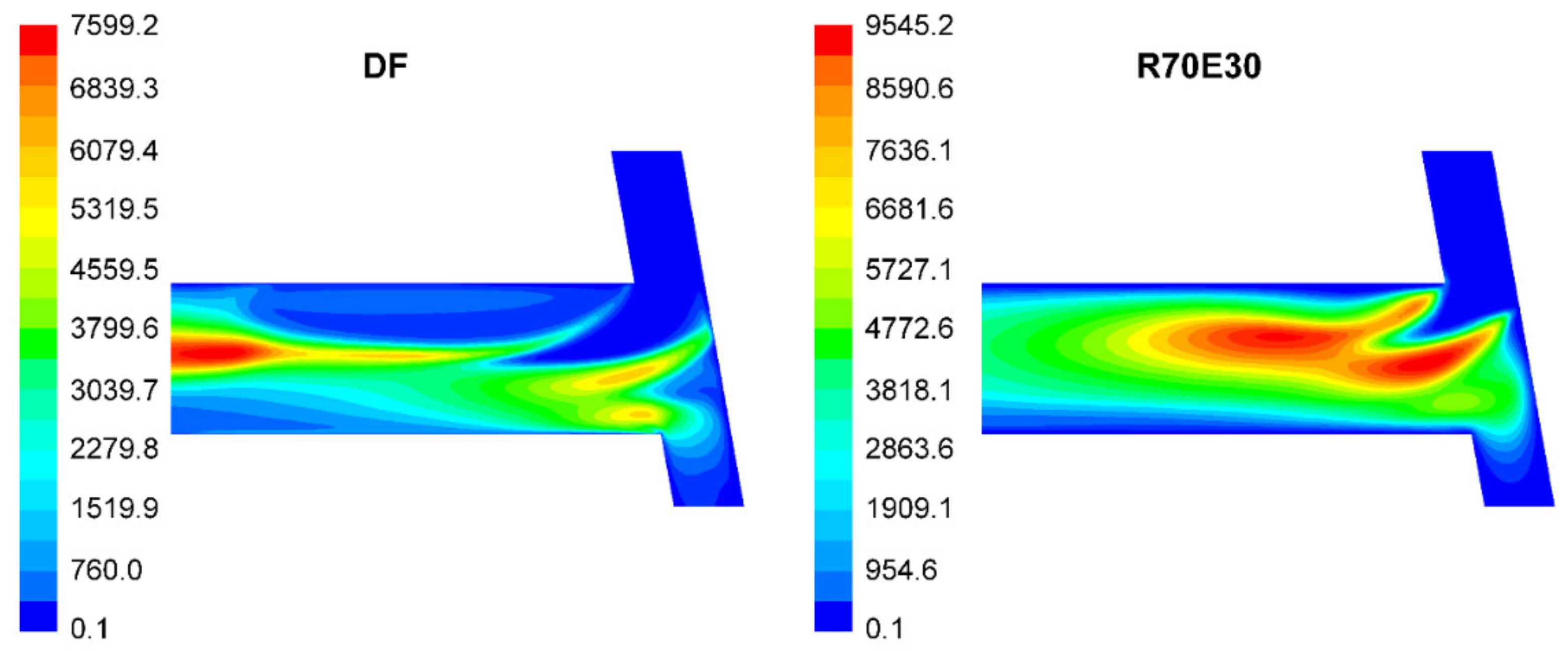
The emulsification of RO with ethanol changes its properties and cavitation regime in the injector nozzle, which significantly impacts the flow parameters in the injector nozzle. Compared with RO, R70E30 has a higher injection velocity but lower FMR and CD. In comparison with DF, R70E30 has higher FMR but lower injection velocity and CD. At backpressure of 0.1 MPa, the TKE at the nozzle hole outlet for R70E30 is more than that for DF. At backpressure of 8.9 MPa, DF has the most TKE at the nozzle hole outlet attributed to the two turbulent cores formed in the nozzle hole.
It should also be noted that the adaptation of engines to work on multicomponent biofuels solves the problem of using local raw materials as a motor fuel. So, in agricultural complexes specializing in animal husbandry, an excess of vegetable oils is formed in the production of oil cake for animal feed. These excessed vegetable oils can be used as a component of motor fuel. This allows the complex use of agricultural products and simplifies the fueling of vehicles and agricultural machinery.

Author Contributions

Conceptualization, V.A.M.; methodology, V.A.M. and S.N.D.; software, B.S.; validation, S.N.D., A.A.Z. and P.R.V.M.; formal analysis, V.A.M. and A.A.Z.; investigation, B.S., S.N.D., P.R.V.M. and S.A.Z.; resources, V.A.M. and A.A.Z.; data curation, A.D.D. and H.C.A.; writing—original draft preparation, P.R.V.M. and H.C.A.; writing—review and editing, V.A.M. and B.S.; visualization, B.S.; supervision, V.A.M.; project administration, S.A.Z. All authors have read and agreed to the published version of the manuscript.

Funding

This research received no external funding.

Data Availability Statement

Data sharing not applicable.

Conflicts of Interest

The authors declare no conflict of interest.

Abbreviations

ABSFCaverage brake-specific fuel consumption
ABTEaverage brake thermal efficiency
BSFCbrake-specific fuel consumption
BTEbrake thermal efficiency
DFdiesel fuel
MFRmass flow rate
IBSCOintegral brake-specific carbon monoxide
IBSHCintegral brake-specific hydrocarbons
IBSNOxintegral brake-specific nitrogen oxides
ROrapeseed oil
R1090% DF + 10% RO
R2080% DF + 20% RO
R3070% DF + 30% RO
R4060% DF + 40% RO
R6040% DF + 60% RO
R23W1057% DF + 23% RO + 10% water
R30W1357% DF + 23% RO + 10% water
R70E3070% RO + 30% ethanol
SVOstraight vegetable oil
TKEturbulent kinetic energy
VFvolume fraction
VOBvegetable oil biodiesel

References

  1. Gül, T.; Kypreos, S.; Turton, H.; Barreto, L. An energy-economic scenario analysis of alternative fuels for personal transport using the Global Multi-regional MARKAL model (GMM). Energy 2009, 34, 1423–1437. [Google Scholar] [CrossRef]
  2. Refaat, A.A. Different techniques for the production of biodiesel from waste vegetable oil. Int. J. Environ. Sci. Technol. 2010, 7, 183–213. [Google Scholar] [CrossRef] [Green Version]
  3. Thiyagarajan, S.; Geo, V.E.; Martin, L.J.; Nagalingam, B. Combined effect of fuel-design and after-treatment system on reduction of local and global emissions from CI engine. Environ. Technol. 2019, 40, 2802–2812. [Google Scholar] [CrossRef] [PubMed]
  4. Agarwal, A.K. Biofuels (alcohols and biodiesel) applications as fuels for internal combustion engines. Prog. Energy Combust. Sci. 2007, 33, 233–271. [Google Scholar] [CrossRef]
  5. Oh, Y.K.; Hwang, K.R.; Kim, C.; Kim, J.R.; Lee, J.S. Recent developments and key barriers to advanced biofuels: A short review. Bioresour. Technol. 2018, 257, 320–333. [Google Scholar] [CrossRef] [PubMed]
  6. Karthikeyan, S.; Prathima, A.; Periyasamy, M.; Mahendran, G. Assessment of the use of Codium Decorticafum [Green seaweed] biodiesel and pyrolytic waste tires oil blends in CI engine. Mater. Today Proc. 2020, 33, 4224–4227. [Google Scholar] [CrossRef]
  7. Shepel, O.; Matijošius, J.; Rimkus, A.; Duda, K.; Mikulski, M. Research of parameters of a compression ignition engine using various fuel mixtures of hydrotreated vegetable oil (Hvo) and fatty acid esters (fae). Energies 2021, 14, 3077. [Google Scholar] [CrossRef]
  8. Park, S.H.; Cha, J.; Lee, C.S. Impact of biodiesel in bioethanol blended diesel on the engine performance and emissions characteristics in compression ignition engine. Appl. Energy 2012, 99, 334–343. [Google Scholar] [CrossRef]
  9. Kumar, H.; Sarma, A.K.; Kumar, P. A novel approach to study the effect of cetane improver on performance, combustion and emission characteristics of a CI engine fuelled with E20 (diesel—bioethanol) blend. Sustain. Chem. Pharm. 2019, 14, 100185. [Google Scholar] [CrossRef]
  10. Ashraful, A.M.; Masjuki, H.H.; Kalam, M.A.; Rizwanul Fattah, I.M.; Imtenan, S.; Shahir, S.A.; Mobarak, H.M. Production and comparison of fuel properties, engine performance, and emission characteristics of biodiesel from various non-edible vegetable oils: A review. Energy Convers. Manag. 2014, 80, 202–228. [Google Scholar] [CrossRef]
  11. Agarwal, A.K.; Shrivastava, A.; Prasad, R.K. Evaluation of toxic potential of particulates emitted from Jatropha biodiesel fuelled engine. Renew. Energy 2016, 99, 564–572. [Google Scholar] [CrossRef]
  12. Khayum, N.; Anbarasu, S.; Murugan, S. Optimization of fuel injection parameters and compression ratio of a biogas fueled diesel engine using methyl esters of waste cooking oil as a pilot fuel. Energy 2021, 221, 119865. [Google Scholar] [CrossRef]
  13. Das, S.; Kashyap, D.; Bora, B.J.; Kalita, P.; Kulkarni, V. Thermo-economic optimization of a biogas-diesel dual fuel engine as remote power generating unit using response surface methodology. Therm. Sci. Eng. Prog. 2021, 24, 100935. [Google Scholar] [CrossRef]
  14. Aguado-Deblas, L.; Estevez, R.; Hidalgo-Carrillo, J.; Bautista, F.M.; Luna, C.; Calero, J.; Posadillo, A.; Romero, A.A.; Luna, D. Outlook for direct use of sunflower and castor oils as biofuels in compression ignition diesel engines, being part of diesel/ethyl acetate/straight vegetable oil triple blends. Energies 2020, 13, 4836. [Google Scholar] [CrossRef]
  15. Dey, P.; Ray, S. Optimization of Waste Vegetable Oil–Diesel Blends for Engine Performance: A Response Surface Approach. Arab. J. Sci. Eng. 2020, 45, 7725–7739. [Google Scholar] [CrossRef]
  16. Markov, V.; Kamaltdinov, V.; Devyanin, S.; Sa, B.; Zherdev, A.; Furman, V. Investigation of the Influence of Different Vegetable Oils as a Component of Blended Biofuel on Performance and Emission Characteristics of a Diesel Engine for Agricultural Machinery and Commercial Vehicles. Resource 2021, 10, 74. [Google Scholar] [CrossRef]
  17. Mirhashemi, F.S.; Sadrnia, H. NOX emissions of compression ignition engines fueled with various biodiesel blends: A review. J. Energy Inst. 2020, 93, 129–151. [Google Scholar] [CrossRef]
  18. Che Mat, S.; Idroas, M.Y.; Hamid, M.F.; Zainal, Z.A. Performance and emissions of straight vegetable oils and its blends as a fuel in diesel engine: A review. Renew. Sustain. Energy Rev. 2018, 82, 808–823. [Google Scholar] [CrossRef]
  19. Ndiaye, P.M.; Tavares, F.W.; Dalmolin, I.; Dariva, C.; Oliveira, D.; Oliveira, J.V. Vapor Pressure Data of Soybean Oil, Castor Oil, and Their Fatty Acid Ethyl Ester Derivatives. J. Chem. Eng. Data 2005, 50, 330–333. [Google Scholar] [CrossRef]
  20. Demirbas, A. Relationships derived from physical properties of vegetable oil and biodiesel fuels. Fuel 2008, 87, 1743–1748. [Google Scholar] [CrossRef]
  21. Das, M.; Sarkar, M.; Datta, A.; Santra, A.K. An experimental study on the combustion, performance and emission characteristics of a diesel engine fuelled with diesel-castor oil biodiesel blends. Renew. Energy 2018, 119, 174–184. [Google Scholar] [CrossRef]
  22. Dey, P.; Ray, S. Comparative analysis of waste vegetable oil versus transesterified waste vegetable oil in diesel blend as alternative fuels for compression ignition engine. Clean Technol. Environ. Policy 2020, 22, 1517–1530. [Google Scholar] [CrossRef]
  23. Costa, M.; Marchitto, L.; Piazzullo, D.; Prati, M.V. Comparison between the energetic and environmental performance of a combined heat and power unit fueled with diesel and waste vegetable oil: An experimental and numerical study. Renew. Energy 2021, 168, 791–805. [Google Scholar] [CrossRef]
  24. Aguado-Deblas, L.; Hidalgo-Carrillo, J.; Bautista, F.M.; Luna, D.; Luna, C.; Calero, J.; Posadillo, A.; Romero, A.A.; Estevez, R. Diethyl ether as an oxygenated additive for fossil diesel/vegetable oil blends: Evaluation of performance and emission quality of triple blends on a diesel engine. Energies 2020, 13, 1542. [Google Scholar] [CrossRef] [Green Version]
  25. Labecki, L.; Cairns, A.; Xia, J.; Megaritis, A.; Zhao, H.; Ganippa, L.C. Combustion and emission of rapeseed oil blends in diesel engine. Appl. Energy 2012, 95, 139–146. [Google Scholar] [CrossRef]
  26. Raman, L.A.; Deepanraj, B.; Rajakumar, S.; Sivasubramanian, V. Experimental investigation on performance, combustion and emission analysis of a direct injection diesel engine fuelled with rapeseed oil biodiesel. Fuel 2019, 246, 69–74. [Google Scholar] [CrossRef]
  27. Qi, D.H.; Lee, C.F.; Jia, C.C.; Wang, P.P.; Wu, S.T. Experimental investigations of combustion and emission characteristics of rapeseed oil–diesel blends in a two cylinder agricultural diesel engine. Energy Convers. Manag. 2014, 77, 227–232. [Google Scholar] [CrossRef]
  28. Consumption of Vegetable Oils Worldwide from 2013/2014 to 2020/2021. Available online: https://www.statista.com/statistics/263937/vegetable-oils-global-consumption/ (accessed on 5 June 2021).
  29. Patel, C.; Tiwari, N.; Agarwal, A.K. Experimental investigations of Soyabean and Rapeseed SVO and biodiesels on engine noise, vibrations, and engine characteristics. Fuel 2019, 238, 86–97. [Google Scholar] [CrossRef]
  30. Deshmukh, D.; Madan Mohan, A.; Anand, T.N.C.; Ravikrishna, R. V Spray characterization of straight vegetable oils at high injection pressures. Fuel 2012, 97, 879–883. [Google Scholar] [CrossRef]
  31. Jain, N.L.; Soni, S.L.; Poonia, M.P.; Sharma, D.; Srivastava, A.K.; Jain, H. A durability study of a compression ignition engine operating with Thumba (Citrullus colocyntis) vegetable oil. Environ. Sci. Pollut. Res. 2019, 26, 8992–9004. [Google Scholar] [CrossRef]
  32. Hoang, A.T.; Le, V.V.; Pham, V.V.; Tham, B.C. An investigation of deposit formation in the injector, spray characteristics, and performance of a diesel engine fueled with preheated vegetable oil and diesel fuel. Energy Sources Part A Recover. Util. Environ. Eff. 2019, 41, 2882–2894. [Google Scholar] [CrossRef]
  33. Agarwal, D.; Kumar, L.; Agarwal, A.K. Performance evaluation of a vegetable oil fuelled compression ignition engine. Renew. Energy 2008, 33, 1147–1156. [Google Scholar] [CrossRef]
  34. Agarwal, A.K.; Dhar, A. Experimental investigations of performance, emission and combustion characteristics of Karanja oil blends fuelled DICI engine. Renew. Energy 2013, 52, 283–291. [Google Scholar] [CrossRef]
  35. Esteban, B.; Riba, J.R.; Baquero, G.; Rius, A.; Puig, R. Temperature dependence of density and viscosity of vegetable oils. Biomass Bioenergy 2012, 42, 164–171. [Google Scholar] [CrossRef] [Green Version]
  36. Yilmaz, N.; Morton, B. Effects of preheating vegetable oils on performance and emission characteristics of two diesel engines. Biomass Bioenergy 2011, 35, 2028–2033. [Google Scholar] [CrossRef]
  37. Chauhan, B.S.; Kumar, N.; Du Jun, Y.; Lee, K.B. Performance and emission study of preheated Jatropha oil on medium capacity diesel engine. Energy 2010, 35, 2484–2492. [Google Scholar] [CrossRef]
  38. Wu, D.; Yu, H.; Harvey, A.; Roskilly, A.P. Micro distributed energy system driven with preheated Croton megalocarpus oil—A performance and particulate emission study. Appl. Energy 2013, 112, 1383–1392. [Google Scholar] [CrossRef]
  39. Jain, N.L.; Soni, S.L.; Poonia, M.P.; Sharma, D.; Srivastava, A.K.; Jain, H. Performance and emission characteristics of preheated and blended thumba vegetable oil in a compression ignition engine. Appl. Therm. Eng. 2017, 113, 970–979. [Google Scholar] [CrossRef]
  40. Senthur Prabu, S.; Asokan, M.A.; Prathiba, S.; Ahmed, S.; Puthean, G. Effect of additives on performance, combustion and emission behavior of preheated palm oil/diesel blends in DI diesel engine. Renew. Energy 2018, 122, 196–205. [Google Scholar] [CrossRef]
  41. Hazar, H.; Aydin, H. Performance and emission evaluation of a CI engine fueled with preheated raw rapeseed oil (RRO)-diesel blends. Appl. Energy 2010, 87, 786–790. [Google Scholar] [CrossRef]
  42. Hazar, H.; Sevinc, H. Investigation of the effects of pre-heated linseed oil on performance and exhaust emission at a coated diesel engine. Renew. Energy 2019, 130, 961–967. [Google Scholar] [CrossRef]
  43. Lin, C.Y.; Wang, K.H. The fuel properties of three-phase emulsions as an alternative fuel for diesel engines. Fuel 2003, 82, 1367–1375. [Google Scholar] [CrossRef]
  44. Rao, N.D.; Premkumar, B.S.; Yohan, M. Study of Use of Different Methods of Using Vegetable Oil as Fuel for Compression Ignition Engine. Glob. J. Res. Eng. Mech. Mech. Eng. 2012, 12, 8–16. [Google Scholar]
  45. Kumar, M.S.; Jaikumar, M. A comprehensive study on performance, emission and combustion behavior of a compression ignition engine fuelled with WCO (waste cooking oil) emulsion as fuel. J. Energy Inst. 2014, 87, 263–271. [Google Scholar] [CrossRef]
  46. Markov, V.A.; Kamaltdinov, V.G.; Savastenko, A.A. Use of Rapeseed Oil and Water Emulsion as Diesel Fuel. In Proceedings of the 2019 International Science and Technology Conference “EastConf”, Vladivostok, Russia, 1–2 March 2019; pp. 1–5. [Google Scholar] [CrossRef]
  47. Čedík, J.; Pexa, M.; Holúbek, M.; Aleš, Z.; Pražan, R.; Kuchar, P. Effect of Diesel Fuel-Coconut Oil-Butanol Blends on Operational Parameters of Diesel Engine. Energies 2020, 13, 3796. [Google Scholar] [CrossRef]
  48. Ochoterena, R.; Lif, A.; Nydén, M.; Andersson, S.; Denbratt, I. Optical studies of spray development and combustion of water-in-diesel emulsion and microemulsion fuels. Fuel 2010, 89, 122–132. [Google Scholar] [CrossRef]
  49. Sharon, H.; Jai Shiva Ram, P.; Jenis Fernando, K.; Murali, S.; Muthusamy, R. Fueling a stationary direct injection diesel engine with diesel-used palm oil-butanol blends—An experimental study. Energy Convers. Manag. 2013, 73, 95–105. [Google Scholar] [CrossRef]
  50. Atmanli, A.; Ileri, E.; Yuksel, B.; Yilmaz, N. Extensive analyses of diesel-vegetable oil-n-butanol ternary blends in a diesel engine. Appl. Energy 2015, 145, 155–162. [Google Scholar] [CrossRef]
  51. Qi, D.; Ma, L.; Chen, R.; Jin, X.; Xie, M. Effects of EGR rate on the combustion and emission characteristics of diesel-palm oil-ethanol ternary blends used in a CRDI diesel engine with double injection strategy. Appl. Therm. Eng. 2021, 199. [Google Scholar] [CrossRef]
  52. Moussa, O.; Tarlet, D.; Massoli, P.; Bellettre, J. Investigation on the conditions leading to the micro-explosion of emulsified fuel droplet using two colors LIF method. Exp. Therm. Fluid Sci. 2020, 116, 110106. [Google Scholar] [CrossRef]
  53. Shen, S.; Sun, K.; Che, Z.; Wang, T.; Jia, M.; Cai, J. Mechanism of micro-explosion of water-in-oil emulsified fuel droplet and its effect on soot generation. Energy 2020, 191, 116488. [Google Scholar] [CrossRef]
  54. Markov, V.A.; Kamaltdinov, V.G.; Denisov, A.D.; Bykovskaja, L.I. Multicomponent Emulsified Biofuels for Transport Diesel Engines. J. Phys. Conf. Ser. 2019, 1260, 52021. [Google Scholar] [CrossRef]
  55. Markov, V.A.; Devyanin, S.N.; Semenov, V.G.; Bagrov, V.V.; Zykov, S.A. Motor Fuels Manufactured from Vegetable Oils; Lambert Academic Publishing: Riga, Latvia, 2019. [Google Scholar]
  56. Liang, Y.; Shu, G.; Wei, H.; Zhang, W. Effect of oxygen enriched combustion and water-diesel emulsion on the performance and emissions of turbocharged diesel engine. Energy Convers. Manag. 2013, 73, 69–77. [Google Scholar] [CrossRef]
  57. Agarwal, A.K.; Som, S.; Shukla, P.C.; Goyal, H.; Longman, D. In-nozzle flow and spray characteristics for mineral diesel, Karanja, and Jatropha biodiesels. Appl. Energy 2015, 156, 138–148. [Google Scholar] [CrossRef] [Green Version]
  58. Qiu, T.; Song, X.; Lei, Y.; Dai, H.; Cao, C.; Xu, H.; Feng, X. Effect of back pressure on nozzle inner flow in fuel injector. Fuel 2016, 173, 79–89. [Google Scholar] [CrossRef]
  59. Kuleshov, A.; Kozlov, A.V.; Mahkamov, K. Self-Ignition Delay Prediction in PCCI Direct Injection Diesel Engines Using Multi-Zone Spray Combustion Model and Detailed Chemistry; SAE Technical Paper 2010-01-1960; SAE Publications: Warrendale, PE, USA, 2010. [Google Scholar] [CrossRef] [Green Version]
  60. Schnerr, G.H.; Sauer, J. Physical and Numerical Modeling of Unsteady Cavitation Dynamics. In Proceedings of the 4th International Conference on Multiphase Flow, New Orleans, LA, USA, 27 May–1 June 2001; pp. 1–12. [Google Scholar]
  61. Schiller, L.; Naumann, Z. A drag coefficient correlation. Z. Ver. Deutsch. Ing. 1935, 77, 318–320. [Google Scholar]
  62. Goldberg, U.; Peroomian, O.; Chakravarthy, S. A Wall-Distance-Free k-ε Model with Enhanced Near-Wall Treatment. J. Fluids Eng. 1998, 120, 457–462. [Google Scholar] [CrossRef]
  63. Sa, B.; Klyus, O.; Markov, V.; Kamaltdinov, V. A numerical study of the effect of spiral counter grooves on a needle on flow turbulence in a diesel injector. Fuel 2021, 290, 120013. [Google Scholar] [CrossRef]
  64. Sa, B.; Markov, V.; Liu, Y.; Kamaltdinov, V.; Qiao, W. Numerical investigation of the effect of multi-walled carbon nanotube additive on nozzle flow and spray behaviors of diesel fuel. Fuel 2021, 290, 119802. [Google Scholar] [CrossRef]
  65. Karabektas, M.; Ergen, G.; Hosoz, M. Effects of the blends containing low ratios of alternative fuels on the performance and emission characteristics of a diesel engine. Fuel 2013, 112, 537–541. [Google Scholar] [CrossRef]
  66. Reşitoğlu, I.A.; Altinişik, K.; Keskin, A. The pollutant emissions from diesel-engine vehicles and exhaust aftertreatment systems. Clean Technol. Environ. Policy 2015, 17, 15–27. [Google Scholar] [CrossRef] [Green Version]
  67. Taghavifar, H. Numerical characterization of transient two-phase flow of nozzle under the impact of diesel fuel temperature and injector backpressure. J. Brazilian Soc. Mech. Sci. Eng. 2020, 42, 1–12. [Google Scholar] [CrossRef]
  68. Sou, A.; Hosokawa, S.; Tomiyama, A. Effects of cavitation in a nozzle on liquid jet atomization. Int. J. Heat Mass Transf. 2007, 50, 3575–3582. [Google Scholar] [CrossRef] [Green Version]
  69. Jin, W. Cavitation generation and inhibition. I. Dominant mechanism of turbulent kinetic energy for cavitation evolution. AIP Adv. 2021, 11, 65028. [Google Scholar] [CrossRef]
Figure 1. Viscosity-temperature characteristics of RO, DF, and DF-RO blends.
Energies 14 06661 g001
Figure 2. Schematic of the combustion chamber and the injector arrangement of the diesel engine D-245. (Length unit is mm.).
Energies 14 06661 g002
Figure 3. Distribution of operation points in the 13-mode steady-state test cycle ECE R49 for vehicle diesel engine. The percentage near each mode is the mode time-share (weighting factor). Red color—full load; green color—part load; orange color—idle.
Energies 14 06661 g003
Figure 4. Mesh model of the investigated nozzle (partial enlargements are shown on the right).
Energies 14 06661 g004
Figure 5. Dependence of brake power Ne, brake torque Me, hourly fuel consumption Gf, excess air ratio α, exhaust smoke opacity Kx, and BSFC ge on the engine speed n of the diesel engine D-245 in the operating conditions of the external characteristic curve for pure DF and R20.
Energies 14 06661 g005
Figure 6. Dependence of hourly fuel consumption Gf (a), volumetric concentrations of nitrogen oxides CNOx (b), carbon monoxide CCO (c), and hydrocarbons CHC (d) in the exhaust gas on the engine speed and brake torque Me for pure DF and R20.
Energies 14 06661 g006aEnergies 14 06661 g006b
Figure 7. The hourly fuel consumption Gf, brake torque Me, excess air ratio α (a), BSFC ge, BTE ηe and exhaust gas smoke Kx (b) for the blended biofuels with different RO content in the operating conditions of the external characteristic curve and the integral brake-specific mass emissions of nitrogen oxides (IBSNOx), carbon monoxide (IBSCO), and hydrocarbons (IBSHC) over the 13 modes (c).
Energies 14 06661 g007
Figure 8. IBSNOx, IBSCO, and IBSHC for DF and emulsified multicomponent biofuels at the 13-mode test cycle (a) and exhaust smoke opacity Kx on the Hartridge scale in the maximum power (Nmax) and maximum torque (Mmax) modes (b).
Energies 14 06661 g008
Figure 9. BTE ηe (a) and BSFC ge (b) for DF and emulsified multicomponent biofuels in the maximum power (Nmax) and maximum torque (Mmax) modes and at the 13-mode test cycle.
Energies 14 06661 g009
Figure 10. IBSNOx over the 13 modes and the exhaust smoke opacity KX in the maximum power mode for DF-RO blend with different RO content (a) and for emulsified DF-RO blend with different water content (b).
Energies 14 06661 g010
Figure 11. Change of axial velocity (a) and phase VF (b) of DF, RO, and R70E30 averaged over the cross-section of the nozzle hole along the hole axis under backpressures of 0.1 and 8.9 MPa.
Energies 14 06661 g011
Figure 12. Distribution of velocity vector of DF in the longitudinal section of the nozzle hole at backpressure of 8.9 MPa.
Energies 14 06661 g012
Figure 13. Distribution of VF of fuel vapors in the longitudinal section of the nozzle hole at two backpressures: (a)—0.1 MPa; (b)—8.9 MPa.
Energies 14 06661 g013
Figure 14. Averaged turbulent kinetic energy (TKE) for DF and R70E30 in cross-section of the nozzle hole along the hole axis under backpressures of 0.1 and 8.9 MPa.
Energies 14 06661 g014
Figure 15. Distribution of TKE (m2/s2) in the longitudinal section of the nozzle hole at backpressure of 8.9 MPa.
Energies 14 06661 g015
Table 1. Physicochemical properties of DF, RO, DF-RO blends, and water-emulsified DF-RO blends [16,54].
Physicochemical PropertiesFuel Type
DFROR20R40R60R23W10R30W13
Density (20 °C), kg/m3830916848865882866.6877.7
Kinematic viscosity (20 °C), mm2/s3.875.09.019.030.08.49.5
Surface tension (20 °C), 10−3 N/m27.133.2-----
Lower calorific value, MJ/kg42.537.341.540.439.436.7535.07
Cetane number4536-----
Flashpoint, °C250318-----
Cloud point, °C−25−9-----
Pour point, °C−35−20-----
Theoretical air-fuel ratio14.312.514.013.613.212.4611.92
Element content, wet% (percentage by weight)
C86.877.084.782.780.774.470.9
H12.612.012.512.312.212.312.2
O0.411.02.74.97.013.216.8
S0.20.0020.160.120.080.130.11
Coking capacity of 10% residue, wet%0.20.4-----
Note: “-”—properties were not determined.
Table 2. Engine specifics.
ParameterValue
Engine typeFour-stroke, in-line, diesel
Number of cylinders (i)4
Cylinder diameter/piston stroke, mm/mm110/125
Engine displacement, L4.32
Compression ratio16.0
Turbocharging systemTurbocharger TKR-6 (Borisov Plant of Automotive Units)
Fuel-air mixing method Space atomization with film evaporation
Rated speed, rpm2400
Rated power, kW80
Power per unit capacity, kW/L18.5
Valve mechanismOverhead valve mechanism
Cooling systemWater, forced circulation
Lubricating systemForced, with splashing
Fuel pumpGear type
Fuel injection systemPump-line-nozzle injection system
High-pressure fuel pump (HPFP)In-line type PP4M10U1f from Motorpal with all-mode centrifugal regulator
Plunger diameter of HPFP, mm 10
Stroke of plunger of HPFP, mm10
Length of high-pressure fuel pipe, mm 540
InjectorsInjector FDM-22 with valve-covered five-hole nozzle
Initial Pressure of injection, MPa21.5
Table 3. Measurement equipment and measurement errors.
IndicatorsMeasurement EquipmentMeasurement Errors
Brake torquedynamometer DS-1036-4U±5 N∙m in 0–500 N∙m
Engine speedspeedometer on flywheel±5 rpm in 0–5000 rpm
Fuel consumptionfuel flowmeter ±0.1 kg/h in 0–40 kg/h
Exhaust smokeMK-3 smoke meter ±1% in 0–100%
NOxSAE-7532 Gas Analyzer±10 ppm in 1000–4000 ppm
COSAE-7532 Gas Analyzer±10 ppm in 0–2000 ppm
HCSAE-7532 Gas Analyzer±10 ppm in 0–2000 ppm
Table 4. Injector nozzle specifics.
Nozzle Hole
Diameter, mm
Nozzle Hole
Length, mm
Nozzle Hole NumberMaximum Lift, mm
0.341.150.32
Table 5. Properties of DF, RO, and ethanol.
Fuel TypeDensity at 40 °C, kg/m3Viscosity at 40 °C, mm2/sSurface Tension at 40 °C, mN/mSaturation Pressure at 40 °C, kPa
DF822.72.426.44.8
RO914.636.032.30
Ethanol782.21.120.618.0
Table 6. Performances of the diesel engine D-245 running on pure DF and DF-RO blends in the operating conditions of the external characteristic curve and 13-mode test cycle.
Engine PerformanceThe Volume Content of RO, %
0204060
BSFC, g/kW·h249.0/225.8255.1/231.8258.1/239.8265.1/243.1
BTE0.340/0.3750.340/0.3740.345/0.3720.345/0.376
Exhaust smoke opacity KX, % on Hartridge scale11.0/25.08.0/16.57.0/13.08.0/11.0
ABSFC over the 13 modes ge_ave, g/kW∙h247.20254.38259.40272.23
ABTE over the 13 modes ηe_ave0.3430.3410.3430.336
IBSNOx over the 13 modes, g/kW·h7.4427.1597.0316.597
IBSCO over the 13 modes, g/kW·h3.4823.8143.8803.772
IBSHC over the 13 modes, g/kW·h1.5190.9650.9491.075
Note: In the first three rows, the engine indicators are given for the operating conditions of the external characteristic curve (the numerator—for the maximum power mode, the denominator—for the maximum torque mode).
Table 7. Hourly fuel consumption and engine brake torque for DF and emulsified multicomponent biofuels in the maximum power (Nmax) and maximum torque (Mmax) modes.
Fuel TypeHourly Fuel Consumption Gf, kg/hBrake Torque Me, N∙m
NmaxMmaxNmaxMmax
DF17.4212.25271355
R23W1018.0712.01254327
R30W1317.9712.20238315
Table 8. Calculated MFR and CD for DF, RO, and R70E30.
BackpressureFuel TypeMFR, g/sCD
0.1 MPaDF14.420.52
RO16.580.56
R70E3014.580.51
8.9 MPaDF14.390.57
RO14.960.56
R70E3014.560.55
Publisher’s Note: MDPI stays neutral with regard to jurisdictional claims in published maps and institutional affiliations.

