Article

Development and Performance Study of Temperature and Humidity Regulator in Baby Incubator Using Fuzzy-PID Hybrid Controller

1
Department of Electrical Engineering, Faculty of Engineering, Universitas Sultan Ageng Tirtayasa, Serang 42435, Indonesia
2
Smart Control for Multi-Agent (SCEMA), Universitas Sultan Ageng Tirtayasa, Banten 42435, Indonesia
3
Computer Science Program, Faculty of Natural Science and Mathematics, Universitas Negeri Jakarta, Jakarta 13220, Indonesia
4
Department of Electrical Engineering, California Polytechnic State University, San Luis Obispo, CA 93407, USA
*
Author to whom correspondence should be addressed.
Energies 2021, 14(20), 6505; https://doi.org/10.3390/en14206505
Submission received: 6 July 2021 / Revised: 20 September 2021 / Accepted: 29 September 2021 / Published: 11 October 2021

Abstract

:
Technological developments in the health sector for the safety of neonates are essential. Such efforts are needed to curb the increase in premature infant mortality cases caused by bacteria, asphyxia, infections, and poor management of facility equipment. Furthermore, preterm and other at-risk babies have low ability to regulate temperature and produce body heat as characterized by their dry skin conditions; hence, the need for baby incubators. For their operation, these baby incubators provide strict regulated energy change that is influenced by heat transfer caused by the surrounding atmospheric temperature and humidity. This paper presents the design, construction, and performance study of a proposed Fuzzy-PID hybrid control system for regulating temperature and humidity in a baby incubator. To accomplish its goal, the proposed controller must be able to distribute heat and maintain humidity in the incubator under fluctuating atmospheric conditions to keep the baby’s body warm. Performance tests of the proposed hybrid controller were conducted by comparing temperature and humidity outputs in the baby incubator against predetermined expected values. Results show that the proposed controller is able to successfully achieve and maintain the temperature and humidity set points. Further examination also suggests that the proposed Fuzzy-PID hybrid control offers an improved overall system response performance compared to the PID controller.

1. Introduction

Premature infant deaths are caused by several reasons including infection, asphyxia, and poor facility management [1], with most occurring in under-developed and developing countries [2]. Furthermore, these unfortunate incidents the first month after birth occur mainly due to negligence in maintaining temperature and humidity in baby incubator as well as baby’s blood oxygen level. In low-income and developing countries, such negligence stems from staff shortage and the declining quality of medical equipment used in hospitals [3]. To address the issue with maintaining the temperature and humidity in a baby incubator; thus, enhancing the quality of the critical medical equipment, a control system that can regulate heat transfer in the incubator is needed. Since heat transfer signifies a change in atmospheric temperature and relative humidity in a place or room [4] [5,6,7]; hence, the ability to maintain and control the amount of heat transfer in baby incubator is very important. One method of achieving this was presented in [8], where sustainable renewable energy based incubators employed a hybrid technique that combined the fuzzy Type-II interval, AHP-TOPSIS with MEA-MLSSVM.
In general, temperature changes all throughout the day [9]. This poses a problem to a baby incubator since its inside temperature must have a normal threshold of about 33 °C to 35 °C with the relative humidity of about 40 to 60% to maintain the stability of a baby’s body temperature and humidity [10,11]. Under such varying temperature, the incubator must therefore be designed to keep its inside temperature warm so that the baby feels comfortable and stays healthy [12]. Such a control can be achieved by implementing the PID control and/or Fuzzy control employing micro-devices to respond to environmental conditions [13]. An example where a combined Fuzzy-Logic PI (F-PI) system was utilized with the Fuzzy-Logic based Sliding Mode Controller for DC-link voltage and Proportional Resonant using Resonant Harmonic Compensator (RHC) is reported in [14]. Another example used fuzzy adaptive backstepping control (F-A-BC) on ocean current turbines in real-time [15], while [16] described the LQR Multivariable PID control system that incorporated state feedback algorithm to find state vector error. Overall, tests of Fuzzy Logic control performance demonstrate the ability to keep the maximum overshoot and the average signal error below 5% [17,18]. Fuzzy-Logic control system is known for its ability to simplify functions and rules, thereby significantly decreasing computation time and memory storage [19]. This advantage fits well with temperature and humidity control system for heating, ventilating, and air-conditioning where Fuzzy-Logic Control (FLC) could provide the convergence and balance properties of the environmental conditions [20]. The FLC system further shows good performance in environmental monitoring for baby care and safety, occupant privacy and family safety [21]. For the baby incubator, the principle and function of each component consist of an adjustable variable light, anti-stray lamp, adjustable accuracy instrument and heat preservation function. The relationship between the ambient and the target temperatures as well as the fluctuation of the incubator temperature can be adjusted as desired [22]. Several other studies on incubator control exist in animals and humans. In poultry, the temperature control system monitors the state of the incubator, automatically changing the incubator’s temperature to that suitable for egg hatching.
All elements were controlled using a programmable integrated circuit (PIC), which is a microcontroller that can process data from sensors and execute control elements to change the condition of the incubator system [23,24]. Moreover, [25] reported a bio-environmental control zone for poultry embryo incubation using infrared heating in which a PID controller maintained a stable air temperature of 34 °C in the incubator.
The design of temperature and humidity controllers for infant incubators has been investigated utilizing various methods such as On-Off, PI, PID, and Fuzzy Logic. In addition, a baby incubator monitoring system to record baby’s condition data into the computer was performed in [26]. The remote monitoring especially for chronic disease patients is important, since it can significantly improve individual’s quality of life, help maintain patients’ independence, prevent further infection, and yields a cost-effective tool [27]. Furthermore, the monitoring system could be used to collect baby’s perceived data and to send emergency notices to a doctor or a nurse [28], while having the ability to control rapid temperature changes in the neonatal incubator [29]. This extended function is crucial since the temperature in the baby incubator should be kept around 36 °C to 38 °C. To achieve this objective, the control system used the Fuzzy-PI controller on the baby incubator for temperature with the DHT11 sensor as the detecting element, and a light bulb as the heat source [30,31]. This system provided quick monitoring and control of temperature through two elements: (1) a microcontroller, which is an integrated circuit designed to perform specific operations in an embedded system, and (2) the LabVIEW software used for testing, measurement, and control applications, with quick access to the device hardware and data. To improve the dynamic and static performances of the temperature control system, the Kalman filter-fuzzy PID algorithm was implemented [32]. Final development of a fuzzy logic control that incorporated incubator air temperature to control heating as well as to model heat transfer of newborns in their environment was presented in [33].
The poultry control system described in [34] was tested using a fuzzy logic simulation of temperature and humidity in an egg incubator affecting hatching time and rate, whose results showed changes in temperature of 1 °C and humidity of 3%, respectively. This method was also adopted for the neonatal incubators, which resulted in accuracy of temperature of less than 0.8 °C and humidity of ±10% [35]. For the baby incubator, the fuzzy logic control was shown to be able to keep the system temperature and humidity at the desired set point and able to adapt the surrounding environment as needed to the baby’s condition [36]. Incubator temperature control that utilizes fuzzy-based PID was studied with MATLAB simulation where two fuzzy logic-based PID controllers and their self-tuning PID algorithm produced the expected improved rise time, settling time and percent overshoot [31]. Another paper formulated the transfer function matrix, where discrete-time system parameters in real-time were studied by the least squares method, where coupling between output and decoupling controller were taken into account in order to eliminate interaction [37]. Lastly, the design and implementation of PID control for baby incubator was also reported in [38,39]
All of the previous studies operated with control algorithms, different heat temperature and humidity transfer models. The control techniques which include ON-OFF, PID, Fuzzy Logic, Fuzzy-PID worked on temperature and humidity variables by utilizing a different heat control system in baby incubators [10,17]. The temperature variable of the PID control system in baby incubators was used by the hardware component of the system and manual simulation [38]. On the other hand, Fuzzy-Logic control systems for temperature and humidity in baby incubators were used by either the hardware or manual simulation [35,36]. The operation of hybrid Fuzzy-PID control system for temperature parameters in incubators was demonstrated solely by MATLAB simulation [30,31]. In this study, a hybrid Fuzzy-PID control system employs an additional humidity variable in baby incubators and implements the Visual Basic Net software for real time hardware measurements. The proposed hybrid control method uses fuzzy logic to fix the Proportional Integral Derivative (PID) controlled parameters for temperature and humidity as the main settings for the baby incubator. This adaptation mechanism aims to maintain stable temperature and humidity inside the baby incubator via adjustment of the actuator, namely the heater or humidifier, upon internal and external environmental changes.

2. Materials and Methods

2.1. Heat Transfer Temperature and Humidity

Heat transfer is energy that is transferred due to a temperature difference. Temperature can be defined as a measure of the degree of hotness or coldness of an object. The science of heat transfer explains how heat energy can move and can also predict the rate of transfer that occurs under certain conditions [5]. The increase in the temperature of an object is proportional to the heat absorbed. The heat absorbed by the object depends on (m) the mass of the object in Kg, (c) the specific heat of the object in J/Kg °C, and the change in temperature of the object that occurs in °C. In mixing several substances, the total heat released is equal to the total heat received, which accordingly explains the occurrence of the mixture temperature (Tc) as the result of mixing several substances following equations:
Q l e t s = Q a c c e p t  
m 1 . c 1 .   ( T 1 T c ) = m 2 . c 2 .   ( T c T 2 )
Air humidity describes the content of water vapor in the air. Relative humidity (RH) is the ratio between the amount of water vapor contained in the air and the maximum amount of water or saturation in the air at the same temperature and air pressure. The relative humidity is expressed in percent (%) [4,7]. Therefore, for the proposed control system the hardware and software designs were based on the analysis of heat and humidity transfers. The hardware and software specifications used in the proposed controller are as follows. First, a laptop serves the function to handle programming and real-time data retrieval. Second, an inside toolbox containing a mini ATmega16 board, power supply circuit, and actuator driver. Third, a baby incubator with its supporting equipment as the plant. The baby incubator measures 65 cm × 45 cm × 35 cm and is made of clear acrylic with thickness of 3 mm. The incubator is equipped with a fan, a 350-Watt incandescent lamp, a humidifier, and an SHT11 sensor. Other research supporting equipment includes multimeter, oscilloscope, cable, solder, tin, and lead suction. Fourth, BASCOM AVR version 2.05.0 serves to create and code programs. Fifth, Visual Basic .NET software provides real time monitoring program for temperature and humidity. The research method and flow-chart which explains the design process of the proposed system as a whole including hardware, programming and software are illustrated in Figure 1.

2.2. Hardware Design

The hardware portion of the proposed incubator control system receives heat and humidity signals from an SHT11 sensor that is outputting digital data. This means no signal conditioning circuit is needed because the output from the sensor can be read by the microcontroller’s internal ADC [30]. The digital data is then displayed directly through an LCD, processed by the microcontroller, and sent via serial communication to a PC continuously (in real-time) with the aid of the VB NET software. This software not only displays measured data and response work graphs in real-time, but it also performs data logging of any changes in temperature and humidity that occur within a certain time interval. The Fuzzy-PID control processes and maintains the temperature and humidity according to the expected set points. The codes for the Fuzzy-PID algorithm are written in Basic with the help of BASCOM AVR software before compiling it into the ATMega16 microcontroller as depicted in Figure 2. When the room temperature and humidity are not at the desired set points, the actuator starts to operate until the set points are reached. The amount of heat is regulated through the adjustment of the applied AC voltage to the heater (lamp) while the air humidity and hot air exhaust are being adjusted through the PWM voltage computed by the microcontroller.
Figure 3 illustrates the block diagram of the proposed system. The AVR ATMega16 system serves to receive and process data, send signals to actuators, and display data on the LCD (Liquid Crystal Display) and PC (Personal Computer). The keypad provides the interface for users to enter the desired set point value. Lastly, the power supply serves to provide the required voltage to the microcontroller system and other actuator circuits.
The ATMega16A microcontroller functions as the brain and a tool for storing programs. The microcontroller reads the sensor and then sends the data to the PC via the RS323 serial circuit. In addition, the microcontroller also acts as a data manager controlling the PID algorithm whose results are used to determine the movement of the actuator. The ATMega16 microcontroller system is made up of several input-output devices whose relationship is shown in Figure 4.

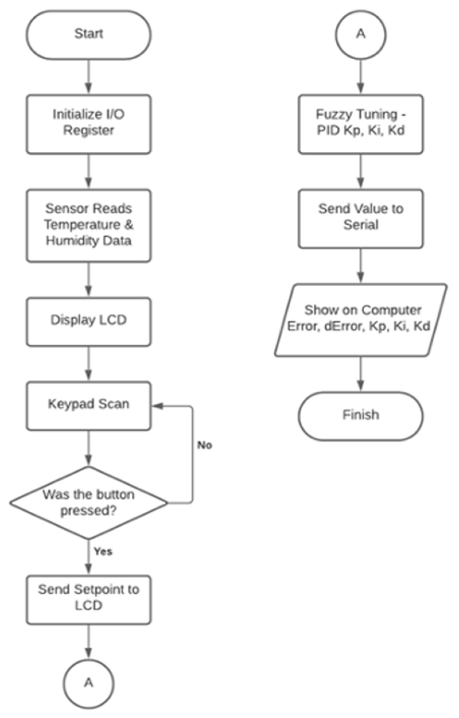
2.3. Software Design

In designing the system interface, Visual Basic.Net, which is an Object-Oriented Program (OPP)-based programming language that is widely used for Graphic Interface Unit (GIU), was utilized as the software to create the system. Visual Basic.Net was chosen because it has quite comprehensive commands and convenient program display with its available editor [12]. For the proposed controller, the interface program consists of two forms: a graphic form aimed at displaying graphs in real time, and a value form aimed at displaying the amount of data processing that occurs in the microcontroller. Figure 5a. shows the graphic form with one T-chart tool which serves to display temperature and humidity real-time readings. The graphic form also includes the ComboBox and Comment Button tools to enable the selection and running of each connected device from the USB serial connection to the computer port slot. Moreover, three TextBox tools are provided that were programmed to automatically bring up the values resulted from Kp, Ki, and Kd computations of the PID in the microcontroller. Figure 5b shows a form value which contains 21 TextBox tools. Each tool automatically generates values from computations performed in the microcontroller such as set point, and current temperature, rule-base and current humidity, present error, previous error, delta error, PID gain values, lamp data value, and fan data value.
The Visual Basic.NET is also being used for monitoring the ATMega16 microcontroller output data. As for the compiler, the AVR BASCOM software uses the Basic programming languages 3.3.1 Main Control Program. The Fuzzy-PID controller integration block diagram is shown in Figure 6. The Fuzzy logic employs the Mamdani method for controlling the temperature and humidity by utilizing error and delta error as inputs, and PID gains Kp, Ki, and Kd as outputs.
The fuzzy control program consists of fuzzification, rule evaluation, decision-making mechanisms, and defuzzification, as illustrated in Figure 7.

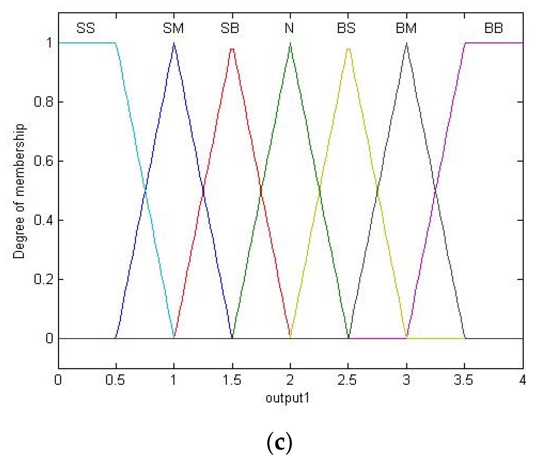
2.4. Member Function

The input function parameters are error and delta error, and the degrees of membership are 0 and 1 [31]. The fuzzification membership functions are shown in Figure 8.
The design of the Fuzzy-PID controller system involved the inputs of the membership function, which are errors and delta errors [31]. The set point value and the actual estimation determine the number of errors and Delta (D) errors following Equations (3) and (4):
Error(e) = Set Point (SP) − Actual Value (PV)
DErrore) = Error (e) − Previous Error (e (k − 1)).
Following the above equations, the Basic programming for the fuzzification line pieces is listed in Appendix A.1.

2.5. Inference Mathematical Model

Fuzzy inference system is a calculation framework that uses its set theory to map out an output from a given input [36]. In this study, two inputs are applied to the proposed system and one output is produced as shown in Appendix A.2.

2.6. Fuzzy Logic Rules

This step entails the process of evaluating the membership degree of each function on the fuzzy set by inputting the predetermined rule base [34]. It is established by the overall rule of the combinations of two inputs, and its output which in turn determines the values of the PID gain constants. Correspondingly, this process constitutes the fuzzy PID rule for the constants Kp, Ki, and Kd, as shown in Table A1, Table A2 and Table A3 in Appendix A.3. This is one of the system inference displays being observed in the correlation of errors (inputs), delta errors (inputs) and outputs in Figure 9.
In programming the microcontroller, the coding pieces are included in Appendix A.4.
For the aforementioned rules, the notations are defined as follows: BB = big-big, BM = big-medium, BS = big-small, N = normal, KS = small-small, KM = small-medium, and KB = small-big. The decision-making method (inference) used in the programming section is the Max-Min procedure. After the fuzzy rules were programmed, the aggregation process was carried out by noting the maximum value of each membership function from the output variable. Following the fuzzification and the rule base steps, defuzzification was carried out. This was intended to allow the output of the fuzzy set to become a crisp (real) value [31]. This change was necessary because the PID control gains only recognize a constant value as a variable parameter [38]. For this purpose, the coding fragment for programming the microcontroller is provided in Appendix A.5. Fuzzy logic controllers are categorized under intelligent control, offering the capability to solve complex system problems when conventional controllers have no ability to do [33]. In the conventional control system, the results are processed and defined with certainty, i.e., it only recognizes 0 and 1 logic or works in the ON and OFF regions. In contrast, the fuzzy logic system defines values that are between 0 and 1, and the controller works intelligently to sense the external environment. For the proposed controller, there are 25 fuzzy logic rules being observed as listed in Appendix A.6.

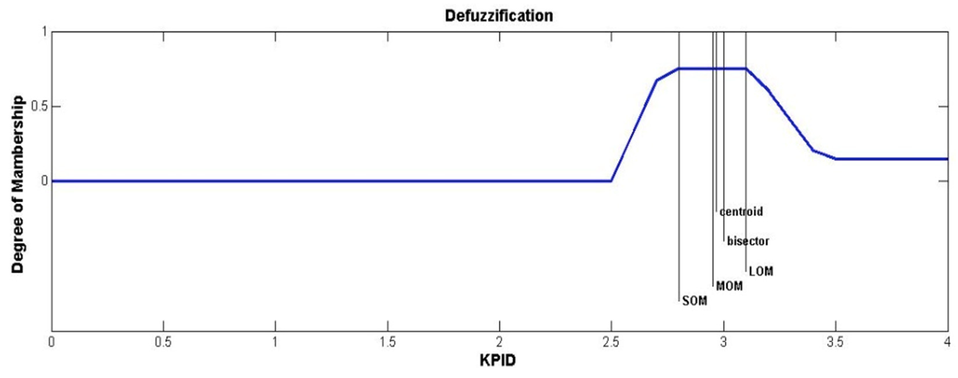
2.7. Defuzzification

The defuzzification process is a fuzzy set obtained from the composition of fuzzy rules, where the resulting output given within a certain range, should be able to take a crisp value [31,36]. It is an inverse of the fuzzification process where mapping is performed to convert fuzzy results into crisp value. There are several methods of defuzzification in the composition of the Mamdani rule, including the center of area (COA), bisector, mean of maximum (MOM), large of maximum (LOM), and Smallest of maximum (SOM) methods. Figure 10 depicts the defuzzification graph in the Mamdani rule with input error −6 and delta error −0.6.
Table 1 lists the results of testing the proposed system using the COA, bisector, MOM, LOM, and SOM defuzzification methods. Results from the input errors for −6 and −0.6, and the KPID consist of Centroid 3.14 s, Bisector 3.08 s, MOM 3 s, LOM 0 s, and SOM 2.92 s. The data obtained show that the best defuzzification method following the reference is the MOM method, where the values resulted from the use of the defuzzification method were taken from the mean of maximum in the fuzzy area.

3. Experimental Results

This section provides a concise description of the experimental results, their interpretation, and conclusions. Hardware testing for controlling temperature and humidity with the Fuzzy-PID method was carried out on a baby incubator as a plant whose physical dimension measured 65 cm × 35 cm × 45 cm in Figure 11a. Inside the plant there was one SHT11 sensor as a temperature and humidity detector in Figure 11b. Complementary to the actuator plant was a lamp type space heater rated at 350 watts, a humidifier, and an exhaust fan as excess heat dissipation. Hardware testing was conducted to determine whether the hardware that had been designed and constructed could work and function optimally as the initial research objectives. Tests carried out on the hardware included measuring the output voltage/signal from each core circuit.

3.1. SHT11 Sensor Characterization Testing

For detecting temperature and humidity, the proposed hybrid controller employs the SHT11 sensors. Prior to testing, these sensors were tested to determine whether they would function properly and follow their theoretical characteristics. First the SHT11 sensors were calibrated by comparing them to other sensors with a higher level of accuracy and precision. The calibration process ran through a program, although ideally each SHT11 sensor had a memory value calibrated by the manufacturer. However, this value may change, and therefore it was necessary to re-calibrate the program using a reference value from a trusted sensor. The final value was then compared to the lower, middle, and upper values according to temperature range between 30 °C and 37 °C, and humidity between 55% RH and 80% RH. Following this step, the value is equated with the arithmetic operator in the program and then retested to prove that the sensor is following the measurement standard. In Table 2, we see that the set point temperature of 30 °C, detected by the SHT11 sensor with an analog thermometer, had a difference representing an error of 1.53 °C, while the error when compared with SHT75 was 0.15 °C. For humidity, digital and analog sensors yielded the largest difference of 5%RH when compared with the characteristics and accuracy of digital and analog sensors. Based on these observations, we concluded that the sensors worked well and consistently following their expected characteristics.
As previously stated, the fuzzification was written in Basic and defined as follows: error Min_error = −10 Max_error = 10 Min_error_negative = −10 Middle_error_negative = −5 Max_error_negative = 0 Min_error_zero = −5 Middle_error_zero = 0 Max_error_zero = 5 Min_error_positive = 0 Middle_error_positive = 5 Max_error_positive = 10 Degree_error_negative = 0 Degree_error_zero = 0 Degree_error_positive = 0 Error_negative = 0 Error_zero = 0 Error_positive = 0 Error_condition_min = 0 Error_condition_max = 0.

3.2. Software Testing

Testing System Response to Set Point

To test the performance of the proposed control system, the temperature set points of 34 °C with humidity varied at 60% RH, 70% RH, and 75% RH were used by Figure 12a–c. At the time of the test, the measured room temperature was at 32.2 °C with humidity of 50.58%. Additionally, the test was conducted during daytime because the temperature and humidity outside of the room were slightly fluctuating compared to those during nighttime.
Figure 10 demonstrate that the system responses well on temperature control when using the proposed Fuzzy-PID hybrid controller. Table 3, Table 4 and Table 5 list values obtained from observations and processed data via MATLAB. Rise time (Tr) is the time required for the system to respond to reach the set point value from the original value. Peak time (Tp) is the time required for the system to reach the maximum peak of a control response from the existing overall value. Mp is the maximum overshoot, which is the maximum value of the spike that has ever been achieved. From these measurements, the temperature control was observed to encounter a slight problem because of the large oscillations before reaching the setting point.

4. Discussion

Hardware testing of the proposed controller was performed during the day due to a relatively stable outdoor temperature. However, the slight fluctuation in the outdoor temperature still imposed a disturbance to the temperature in the incubator. Temperature control of the proposed controller was examined at a set point value of 34 °C and 35 °C from the initial room temperature. The results show that the temperature control with the proposed Fuzzy-PID has a faster response to reach the set point than that of using the PID alone. However, the proposed controller encounters slight difficulty in getting to the set point when interference occurs from the humidity mist actuator output and due to the fluctuating outside temperature of the incubator. Coincidentally, when the disturbance begins to decrease, the controller quickly reaches the set point. Furthermore, the performance of the fan as an actuator was not as good as that of the lamp. The fan used in this study is unfortunately not fast enough to cool the incubator room, unlike the lamp which reacts fast to heat up the room. As a result, the control for lowering the room temperature was not as fast as raising the room temperature. Also, the temperature control at the set point was not strong enough and it lasted too long. For the humidity control, there was a very high fluctuation before reaching the set point value. This was caused by the difficulty in optimally operating the actuator to regulate the air/humidity levels. External factors or the conditions inside the incubator may have contributed to such difficulty. Additionally, there was heat disturbance from temperature actuators which affected the quality of humidity in the air.
Hardware test results performed on the proposed controller are summarized as follows. First, the power supply circuit receives 200 Vrms from an AC source, which is then lowered using a transformer and further rectified to a DC voltage by a full-wave diode rectifier circuit. The resulting DC voltage passes through the LM2576 regulator to produce a theoretical well-regulated 5 Volts. However, this voltage was actually at 4.9 Volts when measured by a multimeter. This is because the feedback resistors were not fine-tuned to yield the exact 5 Volt output. The linear regulator output supplies the microcontroller which can provide approximately 4.82 Volts that is being used as a reference voltage for the sht11 sensor. Secondly, analysis of temperature and humidity controls was performed from the tests conducted during daytime due to the slightly fluctuating outdoor temperature. Regardless, the slight variation in the temperature still introduced a disturbance to the temperature in the incubator. Temperature control to test the proposed controller was carried out at set point values of 34 °C and 35 °C from the initial room temperature. The results show that the proposed Fuzzy-PID controller outperformed the PID controller specifically in reaching the set point fast despite the interference from the humidity actuator. The response of the proposed controller was even better when the disturbance began to decrease. One hardware issue relates to the fan used as an actuator in the incubator which needs to be replaced with a better quality one. The reason for this is due to the inherent slow-reacting time of the current fan which caused the lowering temperature controller action during testing to be slower than that for raising temperature.

5. Conclusions

In this paper, a temperature and humidity control system for a baby incubator with a hybrid Fuzzy-PID controller system to regulate its temperature and humidity has been presented. The proposed controller utilizes a lamp used as a heater and an ultrasonic humidifier as a humidifier. Hardware test results demonstrate that the integration of temperature and humidity controls with the hybrid Fuzzy-PID on a baby incubator successfully achieved the expected temperature and humidity values in the baby incubator. The results further show the advantage of the Fuzzy-PID hybrid controller in regulating the voltage-based devices such as the lamp (heater), fan (exhaust fan), and fog generator (humidifier), which worked together to achieve the temperature and humidity set points in the baby incubator. However, test results also indicate that internal and external disturbances could interfere in producing the set point values and stability of the system.

Author Contributions

The main part of the research work, namely, concepts, methodology, simulation, experimental settings, analysis of the results, and preparation of the manuscript was designed and carried out by A.A., P.H. contributed greatly to the methodology, simulation, and experimental components. The methodology development and manuscript preparation were also performed with the assistance of R.A. (Ria Arafiyah), A.A., I.S., R.A. (Rocky Alfanz) and T.T., that contributed to the review of the manuscript. All authors have read and agreed to the published version of the manuscript.

Funding

This research received no external funding.

Data Availability Statement

The data that support the findings of this study are available from the corresponding author upon reasonable request.

Acknowledgments

All expertise assistance and technical contribution on this research and all reviewers have provided suggestions for this paper.

Conflicts of Interest

The authors declare no conflict of interest.

Appendix A

Appendix A.1. The Basic Programing for Fuzzification Line Pieces

’error
Min_error = −10
Max_error = 10
Min_error_negative = −10
Middle_error_negative = −5
Max_error_negative = 0
Min_error_zero = −5
Middle_error_zero = 0
Max_error_zero = 5
Min_error_positive = 0
Middle_error_positive = 5
Max_error_positive = 10
Degree_error_negative = 0
Degree_error_zero = 0
Degree_error_positive = 0
Error_negative = 0
Error_zero = 0
Error_positive = 0
Error_condition_min = 0
Error_condition_max = 0

Appendix A.2. Mathematical Model Inference

Appendix A.2.1. Error Input

μ NB [ x ] { 1 15 x 10 5 x 5 , 10 x 5 0 x 5   U   x 15
μ NS [ x ] { x + 10 5 15 x 10 x 5 , 5 x 0 0 x 0   U   x 10
μ Z [ x ] { x + 5 5 5 x 0 5 x 5 , 0 x 5 0 x 5   U   x 5
μ PS [ x ] { x 5 5 0 x 5 10 x 5 , 5 x 10 0 x 10   U   x 0
μ NB [ x ] { 1 10 x 15 x 5 5 , 5 x 10 0 x 15   U   x 5

A.2.2. Delta-Error Input

μ NB [ x ] { 1 15 x 10 5 x 5 , 10 x 5   0 x 5   U   x 15
μ NS [ x ] { x + 10 5 15 x 10 x 5 , 5 x 0 0 x 0   U   x 10
μ Z [ x ] { x + 5 5 5 x 0 5 x 5 ,   0 x 5 0 x 5   U   x 5
μ PS [ x ] { x 5 5 0 x 5 10 x 5 ,     5 x 10 0 x 10   U   x 0
μ NB [ x ] { 1 10 x 15 x 5 5 , 5 x 10 0 x 15   U   x 5

A.2.3. Output

μ SS [ x ] { 1 0 x 0.5 1 x 0.5 , 0.5 x 1 0 x 1   U   x 0
μ SM [ x ] { x 0.5 0.5 0.5 x 1 1.5 x 0.5 , 1 x 1.5 0 x 1.5   U   x 0.5
μ SB [ x ] { x 1 0.5 1 x 1.5 2 x 0.5 , 1.5 x 2 0 x 2   U   x 1
μ N [ x ] { x 1.5 0.5 1.5 x 2 2.5 x 0.5 , 2 x 2.5 0 x 2.5   U   x 1.5
μ BS [ x ] { x 2 0.5 2 x 2.5 3 x 0.5 , 2.5 x 3 0 x 3   U   x 2
μ BM [ x ] { x 2.5 0.5 2.5 x 3 3.5 x 0.5 , 3 x 3.5 0 x 3.5   U   x 2.5
μ NB [ x ] { 1 3.5 x 4 x 3 0.5 , 3 x 3.5 0 x 4   U   x 3

Appendix A.3. Fuzzy Logic Rules Tables Fuzzy-Pid (Kp, Ki and Kd)

Table A1. Fuzzy -PID Tuning Rules for Constant Kp.
Kp∆E
NBNSZPSPB
ENBBBPMPMBSN
NSPMPMBSNKS
ZPMBSNKSKM
PSBSNKSKSKM
PBNKMKMKMKB
Table A2. Fuzzy-PID Tuning Rules for Constant Ki.
Ki∆E
NBNSZPSPB
ENBKBKMKMKSN
NSKBKMKSKSN
ZKMKSNBSBM
PSNMNSBSBSBB
PBNBSBMBMBB
Table A3. Fuzzy-PID Tuning Rules for Constant Kd.
Kd∆E
NBNSZPSPB
ENBKSKMKMKMKS
NSNKMKMKSN
ZNKSKSKSN
PSNNNNN
PBBMBMBMKSBM

Appendix A.4. In Programming the Microcontroller the Coding Piece

error
If Curr_error >= Min_error_negative And Curr_error < Max_error_negative Then
Error_negative = 1
End If
If Curr_error > Min_error_zero And Curr_error < Max_error_zero Then
Error_zero = 1
End If
If Curr_error > Min_error_positive And Curr_error < Max_error_positive Then
Error_positive = 1
End If
If Error_negative = 1 Then
If Curr_error >= Min_error_negative And Curr_error <= Middle_error_negative Then
Degree_error_negative = 1
Elseif Curr_error > Middle_error_negative And Curr_error < Max_error_negative Then
Degree_error_negative = Curr_error / -5
Else
Degree_error_negative = 0
End If
End If

Appendix A.5. The Coding Fragment for Programming the Microcontroller

If Error_condition_max > Derror_condition_max Then
Condition_1 = Derror_condition_max
Else
Condition_1 = Error_condition_max
End If
If Error_condition_min > Derror_condition_min Then
Condition_2 = Derror_condition_min
Else
Condition_2 = Error_condition_min
End If
Condition_1 = Condition_1 * 10
Condition_2 = Condition_2 * 10
Condiiton = Condition_1 + Condition

Appendix A.6. This Study Used 25 Fuzzy Logic Rules

  • If (error is NB) and (DeltaError is NB) then (output1 is BB) (1)
  • If (error is NS) and (DeltaError is NB) then (output1 is BM) (1)
  • If (error is z) and (DeltaError is NB) then (output1 is BM) (1)
  • If (error is PS) and (DeltaError is NB) then (output1 is BS) (1)
  • If (error is PB) and (DeltaError is NB) then (output1 is N) (1)
  • If (error is NB) and (DeltaError is NS) then (output1 is BM) (1)
  • If (error is NS) and (DeltaError is NS) then (output1 is BM) (1)
  • If (error is z) and (DeltaError is NS) then (output1 is BS) (1)
  • If (error is PS) and (DeltaError is NS) then (output1 is N) (1)
  • If (error is PB) and (DeltaError is NS) then (output1 is SM) (1)
  • If (error is NB) and (DeltaError is Z) then (output1 is BM) (1)
  • If (error is NS) and (DeltaError is Z) then (output1 is BS) (1)
  • If (error is z) and (DeltaError is Z) then (output1 is N) (1)
  • If (error is PS) and (DeltaError is Z) then (output1 is SS) (1)
  • If (error is PB) and (DeltaError is Z) then (output1 is SM) (1)
  • If (error is NB) and (DeltaError is PS) then (output1 is BS) (1)
  • If (error is NS) and (DeltaError is PS) then (output1 is N) (1)
  • If (error is z) and (DeltaError is PS) then (output1 is SS) (1)
  • If (error is PS) and (DeltaError is PS) then (output1 is SS) (1)
  • If (error is PB) and (DeltaError is PS) then (output1 is SM) (1)
  • If (error is NB) and (DeltaError is PB) then (output1 is N) (1)
  • If (error is NS) and (DeltaError is PB) then (output1 is SS) (1)
  • If (error is z) and (DeltaError is PB) then (output1 is SM) (1)
  • If (error is PS) and (DeltaError is PB) then (output1 is SM) (1)
  • If (error is PB) and (DeltaError is PB) then (output1 is SB) (1)

References

  1. Fadilla, R.; Idhil, A.N.I.I.; Anggraini, M.A.P.; Dewi, A.K.; Sanjaya, M.R.; Nurrohman, M.Y. Rahmadwati A Multifunction Infant Incubator Monitoring System with Phototherapy and ESP-32 Based Mechanical Swing. Int. J. Sci. Technol. Manag. 2020, 1, 371–381. [Google Scholar] [CrossRef]
  2. Belizán, J.M.; McClure, E.M.; Goudar, S.S.; Pasha, O.; Esamai, F.; Patel, A.; Chomba, E.; Garces, A.; Wright, L.L.; Koso-Thomas, M.; et al. Neonatal Death in Low- to Middle-Income Countries: A Global Network Study. Am. J. Perinatol. 2012, 29, 649–656. [Google Scholar] [CrossRef] [PubMed] [Green Version]
  3. Zaid, A.S.; Yahya, Y.Z.; Kandemirli, F. LabVIEW BASED TEMPERATURE CONTROL SYSTEM FOR NEONATAL INCUBATOR. Eurasian J. Sci. Eng. Technol. 2020, 1, 20–26. Available online: https://dergipark.org.tr/en/pub/ejset/725589 (accessed on 20 April 2021).
  4. Wei, M.; Wang, B.; Liu, S. Numerical Simulation of Heat and Moisture Transfer of Wall with Insulation. J. Phys. Conf. Ser. 2019, 1300, 1–8. [Google Scholar] [CrossRef]
  5. Voelker, C.; Hoffmann, S.; Kornadt, O.; Arens, E.; Zhang, H.; Huizenga, C. Heat And Moisture Transfer Through Clothing. Science 2009, 11, 1360–1366. [Google Scholar]
  6. Ren, T.; Li, A.; Lv, W. Field and Laboratory Tests and Analyses on Temperature and Relative Humidity in Underground Multi-tunnels. Procedia Eng. 2017, 205, 27–34. [Google Scholar] [CrossRef]
  7. Sobolewski, A.; Młynarczyk, M.; Konarska, M.; Bugajska, J. The influence of air humidity on human heat stress in a hot environment. Int. J. Occup. Saf. Ergon. 2021, 27, 226–236. [Google Scholar] [CrossRef]
  8. Liang, G.; Niu, D.; Liang, Y. Sustainability Evaluation of Renewable Energy Incubators Using Interval Type-II Fuzzy AHP-TOPSIS with MEA-MLSSVM. Sustainability 2021, 13, 1796. [Google Scholar] [CrossRef]
  9. Hariyanto, M.W.; Hendrawan, A.H.; Ritzkal, R. Monitoring the Environmental Temperature of the Arduino Assistance Engineering Faculty Using Telegram. J. Robot. Control. (JRC) 2020, 1, 96–101. [Google Scholar] [CrossRef] [Green Version]
  10. Latif, A.; Widodo, H.A.; Atmoko, R.A.; Phong, T.N.; Helmy, E.T. Temperature and Humidity Controlling System for Baby Incubator. J. Robot. Control. (JRC) 2021, 2, 190–193. [Google Scholar] [CrossRef]
  11. Usman, A.; Marwazi, H.; Alam, S. Temperature and humidity test of the telemetry tool modeling in baby incubator. Sanitas 2018, 9, 16–23. [Google Scholar] [CrossRef] [Green Version]
  12. Latif, A.; Arfianto, A.Z.; Poetro, J.E.; Phong, T.N.; Helmy, E.T. Temperature Monitoring System for Baby Incubator Based on Visual Basic. J. Robot. Control. (JRC) 2021, 2, 47–50. [Google Scholar] [CrossRef]
  13. Li, Y.; Dou, W.; Zhou, C.; Wang, X.; Yang, A.; Zhang, Y.; Qiao, D. A Microtester for Measuring the Reliability of Microdevices in Controlled Environmental Conditions. Micromachines 2021, 12, 585. [Google Scholar] [CrossRef] [PubMed]
  14. Zeb, K.; Islam, S.U.; Din, W.U.; Khan, I.; Ishfaq, M.; Busarello, T.D.C.; Ahmad, I.; Kim, H.J. Design of Fuzzy-PI and Fuzzy-Sliding Mode Controllers for Single-Phase Two-Stages Grid-Connected Transformerless Photovoltaic Inverter. Electronics 2019, 8, 520. [Google Scholar] [CrossRef] [Green Version]
  15. Shen, X.; Xie, T.; Wang, T. A Fuzzy Adaptative Backstepping Control Strategy for Marine Current Turbine under Disturbances and Uncertainties. Energies 2020, 13, 6550. [Google Scholar] [CrossRef]
  16. Guardeño, R.; López, M.J.; Sánchez, V.M. MIMO PID Controller Tuning Method for Quadrotor Based on LQR/LQG Theory. Robotics 2019, 8, 36. [Google Scholar] [CrossRef] [Green Version]
  17. Widhiada, W.; Negara, D.N.; Suryawan, P.A. Temperature Distribution Control for Baby Incubator System Using Arduino AT Mega 2560. Bali Indones. 2017, 19, 1748–1751. Available online: https://simdos.unud.ac.id/uploads/file_penelitian_1_dir/d8cee6e73f739dc11ac9590012345664.pdf (accessed on 17 June 2021).
  18. Goksu, O.F.; Arabul, A.Y.; Vurol, R.A. Low Voltage Battery Management System with Internal Adaptive Charge and Fuzzy Logic Controller. Energies 2020, 13, 2221. [Google Scholar] [CrossRef]
  19. Musa, S.; Radzi, M.A.M.; Hizam, H.; Wahab, N.I.A.; Hoon, Y.; Zainuri, M.A.A.M. Modified Synchronous Reference Frame Based Shunt Active Power Filter with Fuzzy Logic Control Pulse Width Modulation Inverter. Energies 2017, 10, 758. [Google Scholar] [CrossRef]
  20. Ibrahim, B.S.K.I.; Aziah, M.; Ahmad, S.; Akmeliawati, R.; Nizam, H.; Muthalif, A.G.A.; Toha, S.; Hassan, I.D.M.K. Fuzzy-based Temperature and Humidity Control for HV AC of Electric Vehicle. Procedia Eng. 2012, 41, 904–910. [Google Scholar] [CrossRef] [Green Version]
  21. Lü, B.; Pei, C.Q.; Tian, J.S.; Wen, W.L.; Wang, J.F.; Tian, J.S. Design and Implementation of the Intelligent Streak Camera Control System Based on Internet of Things. Acta Photonica Sin. 2017, 46, 522002. [Google Scholar] [CrossRef]
  22. Li, S.; Qu, Z.; Song, Z. A Multifunctional Combination Incubator. Energies 2020, 13, 6622. [Google Scholar] [CrossRef]
  23. Uzoigwe, L.O.; Elkezie, J.C. Egg Incubator Control System with Short Message Service (SMS) Fault Analysis Alert. J. Fac. Agric. Vet. Med. 2013, 11, 45–68. [Google Scholar] [CrossRef]
  24. Olasunkanmi, J.N.; Akintade, O.O.; Kehinde, L.O. Development of a GSM based DC Powered Bird Egg Incubator. J. Eng. Res. Technol. 2015, 4, 104–109. Available online: www.ijert.org (accessed on 29 September 2021).
  25. Youssef, A.; Norton, T.; Berckmans, D. Bioenvironmental Zonal Controlling of Incubated Avian Embryo Using Localised Infrared Heating. Processes 2019, 7, 651. [Google Scholar] [CrossRef] [Green Version]
  26. Ishak, D.N.F.M.; Jamil, M.M.A.; Bin Ambar, R. Arduino Based Infant Monitoring System. In IOP Conference Series: Materials Science and Engineering; IOP Publishing: Melaka, Malaysia, 2017; Volume 226, p. 012095. [Google Scholar]
  27. Agresara, M.N.; Vyas, D.D.; Bhensdadiya, B.S. System for Remote Monitoring and Control of Baby Incubator and Warmer. System 2016, 3, 6. [Google Scholar]
  28. Radhika, B.; Sheshagiri Rao, V.R. Incubator baby parameter sensing and monitoring. Int. J. Innov. Technol. Explor. Eng. 2019, 8, 2945–2947. [Google Scholar]
  29. Al-Sawaff, Z.H.; Yahya, Y.Z.; Kandemirli, F. Neonatal Incubator Embedded Temperature Observation and Monitoring Using GSM. J. Eng. Res. Rep. 2019, 4, 1–9. [Google Scholar] [CrossRef]
  30. Shabaan, A.R.; El-Metwally, S.M.; Farghaly, M.M.; Sharawi, A.A. PID and fuzzy logic optimized control for temperature in infant incubators. In Proceedings of the 2013 5th International Conference on Modelling, Identification and Control (ICMIC), Cairo, Egypt, 31 August–2 September 2013; pp. 53–59. [Google Scholar]
  31. Utomo, S.B.; Irawan, J.F.; Mujibtamala, A.; Nari, M.I.; Amalia, R. Automatic baby incubator system with fuzzy-PID controller. In IOP Conference Series: Materials Science and Engineering; IOP Publishing: Malang, Indonesia, 2021; Volume 1034, p. 012023. [Google Scholar]
  32. Jin, A.; Wu, H.; Zhu, H.; Hua, H.; Hu, Y. Design of temperature control system for infant radiant warmer based on Kalman filter-fuzzy PID. In Journal of Physics: Conference Series; IOP Publishing: Shanghai, China, 2020; Volume 1684, p. 012140. [Google Scholar]
  33. Soesanti, I.; Syahputra, R. A Fuzzy Logic Controller Approach for Controlling Heat Exchanger Temperature. J. Electr. Technol. UMY 2019, 3, 117–124. [Google Scholar] [CrossRef] [Green Version]
  34. Wang, R. The Design of Temperature and Humidity Control System Based on Fuzzy Control in Multi Incubators. In Advances in Electronic Engineering, Communication and Management; Springer: Berlin/Heidelberg, Germany, 2012; pp. 15–18. [Google Scholar]
  35. Flores, S.A.I.; Konno, H.J.; Massafra, A.M.; Schiaffino, L. Simultaneous Humidity and Temperature Fuzzy Logic Control in Neonatal Incubators. In Proceedings of the 2018 Argentine Conference on Automatic Control (AADECA), Buenos Aires, Argentina, 7–9 November 2018. [Google Scholar]
  36. Marwanto, A.; Sunriyadi, K.; Alifah, S. Fuzzy Logic Implementation For Incubator Prototype With Temperature And Humidity Control. In Proceedings of the 2019 6th International Conference on Electrical Engineering, Computer Science and Informatics (EECSI), Bandung, Indonesia, 18–20 September 2019; pp. 71–74. [Google Scholar]
  37. Zermani, M.A.; Feki, E.; Mami, A. Multivariable control applied to temperature and humidity case study: Neonate incubator. In Proceedings of the 2012 20th Mediterranean Conference on Control & Automation (MED), Barcelona, Spain, 3–6 July 2012; pp. 1440–1445. [Google Scholar]
  38. Theopaga, A.K.; Rizal, A.; Susanto, E. Design and implementation of PID control based baby incubator. J. Theor. Appl. Inf. Technol. 2014, 70, 19–24. [Google Scholar]
  39. Widhiada, W.; Antara, I.N.G.; Budiarsa, I.N.; Karohika, I.M.G. The Robust PID Control System of Temperature Stability and Humidity on Infant Incubator Based on Arduino AT Mega 2560. In IOP Conference Series: Earth and Environmental Science; IOP Publishing: Jeju Island, Korea, 2019; Volume 248, p. 012046. [Google Scholar]
Figure 1. Research method and steps of Fuzzy-PID Hybrid control system on baby incubator.
Energies 14 06505 g001
Figure 2. BASCOM AVR Program Form.
Energies 14 06505 g002
Figure 3. Diagram block of system control design.
Energies 14 06505 g003
Figure 4. Input relation dan microcontroller port output.
Energies 14 06505 g004
Figure 5. (a) Visual Basic.Net Work Window Display (b) Value form display.
Energies 14 06505 g005
Figure 6. Block diagram of Fuzzy-PID hybrid control on the baby incubator.
Energies 14 06505 g006
Figure 7. Model Fuzzy Interference System.
Energies 14 06505 g007
Figure 8. (a) Degree of membership error (input), (b) Degree of membership delta error (Input) and (c). Degree of Membership (Output).
Energies 14 06505 g008aEnergies 14 06505 g008b
Figure 9. The surface of error, delta error and output variable.
Energies 14 06505 g009
Figure 10. Defuzzification with COA, bisector, MOM, LOM, and SOM methods.
Energies 14 06505 g010
Figure 11. (a) Microcontroller Arduino, SHT11 Sensor and LCD and (b) Baby Incubator.
Energies 14 06505 g011
Figure 12. (a) System response for temperature 34 °C and humidity 60%, (b). System response for temperature 34 °C and humidity 70% and (c) System response for temperature 34 °C and humidity 75%.
Energies 14 06505 g012aEnergies 14 06505 g012b
Table 1. Defuzzification.
ErrorDelta ErrorDefuzzificationAverage
CentroidBisectorMOMLOMSOM
−15−1.53.623.643.7603.522.908
−12−1.23.623.643.7603.522.908
−9−0.93.53.563.7203.442.844
−6−0.63.143.08302.922.428
−3−0.32.562.642.9802.62.156
00222021.6
30.31.020.680.34000.408
60.60.6430.520.3000.2926
90.91.21.361.4801.41.088
121.21.51.481.501.481.192
Table 2. Comparison test results of digital and analog sensors.
SETPOINT.Sensor Reading Result
SHT11SHT75ANALOG
(°C)(%RH)Temp
(°C)
Hum
(%RH)
Temp
(°C)
Hum
(%RH)
Temp
(°C)
Hum
(%RH)
305530.235730.0956.7831.760
326031.9961.732.0860.833.564.4
34703470.83470.534.574.1
368036.018136.028136.276
Table 3. Characteristics of the System response to the set point temperature 34 °C and humidity 60%.
ParameterTemperature = 34 °CRelative Humidity = 60% RH
Rise Time (Tr)65.8 s4.4773 s
Settling Time (ts)111.3812 s
Max. Overshoot-7.41%
Peak Time (tp)116 s16 s
Table 4. Characteristics of the system response to set point temperature 34 °C and humidity 70%.
ParameterT = 34 °CRelative Humidity = 70% RH
Rise Time (Tr)82.02 s13.158 s
Settling Time (ts)-142 s
Max. Overshoot0.26%5.73%
Peak Time (tp)176 s66 s
Table 5. Characteristics of the system response to set point temperature 34 °C and humidity 75%.
ParameterTemperature = 34 °CRelative Humidity = 75% RH
Rise Time (Tr)212.25 s19.677 s
Settling Time (ts)261 s186 s
Max. Overshoot0.44%5.42%
Peak Time (tp)255 s93 s
Publisher’s Note: MDPI stays neutral with regard to jurisdictional claims in published maps and institutional affiliations.

