Article

Numerical Simulation of Pulsed Gravel Packing Completion in Horizontal Wells

1
College of Safety and Ocean Engineering, China University of Petroleum, Beijing 102249, China
2
Department of Chemical and Petroleum Engineering, University of Calgary, Calgary, AB T2N1N4, Canada
3
SINOPEC Yanshan Company, Beijing 102500, China
*
Author to whom correspondence should be addressed.
Energies 2021, 14(2), 292; https://doi.org/10.3390/en14020292
Submission received: 13 December 2020 / Revised: 29 December 2020 / Accepted: 30 December 2020 / Published: 7 January 2021
(This article belongs to the Special Issue Advances and Challenges in Harvesting Ocean Energy)

Abstract

:
The gravel packing completion method for horizontal wells has the advantages of maintaining high oil production for a long time, maintaining wellbore stability, and preventing sand production, so it has become the preferred completion method for horizontal wells. At present, this technology still faces the problems of high sand bed height and poor gravel migration. In order to improve the efficiency of gravel packing in horizontal wells, pulsed gravel packing technology for horizontal wells is proposed for the first time. Based on the mechanism of hydraulic pulse, the Eulerian–Eulerian model, k-ε model based on the renormalization group theory (RNG k-ε model), and Fluent are used to simulate the solid-liquid two-phase flow. By optimizing the parameters such as frequency and amplitude of pulse waveform, the optimal pulse waveform of pulsed gravel packing in horizontal wells is determined. The effects of parameters such as sand-carrying fluid displacement, sand-carrying fluid viscosity, sand-carrying ratio, gravel particle size, and string eccentricity on pulsed gravel packing in horizontal wells are studied, and the distribution law of gravel migration velocity and volume fraction in horizontal wells is obtained. According to the results, it can be seen that with the increase of displacement and viscosity of carrier fluid, the volume fraction of fixed bed and moving bed decreases gradually, while that of suspension bed increases gradually. With the increase of sand-carrying ratio, gravel particle size, and string eccentricity, the volume fraction of fixed bed and moving bed increases gradually, while that of suspended bed decreases gradually. Comparing the effects of conventional gravel packing and pulsed gravel packing in horizontal wells, it can be concluded that the efficiency of pulsed gravel packing in horizontal wells is higher. The volume fraction of fixed bed and moving bed decreased by 30% and 40% respectively, while the volume fraction of suspended bed increased by 20%. The migration velocity of moving bed and suspended bed increased by 40% and 25%, respectively, and the migration ability of gravel improved obviously.

1. Introduction

With the rapid development of the petroleum industry, the advantages and remarkable economic benefits of using horizontal wells to exploit oil and gas fields have been paid more attention by all countries in the world, especially the exploitation of offshore oil fields with horizontal wells, which has a broader application prospect [1,2]. The gravel packing completion method for horizontal wells has the advantages of maintaining high production of oil wells, maintaining wellbore stability, and preventing sand production from the formation for a long time [3]. Especially for unconsolidated sandstone reservoirs with severe sand production, the gravel packing completion method for horizontal wells is a sand control completion technology with good effect, which has become the preferred completion method in modern oil wells [4]. However, the sand bed plugging problem still exists in gravel packing operation of horizontal wells, which hinders the large-scale application of gravel packing technology in horizontal wells.
For the above problems, scholars have conducted a lot of research on the gravel packing technology of horizontal wells. Forrest [5] established a gravel packing simulation experiment device to carry out experiments on the gravel packing process in the annulus of highly deviated wells and horizontal wells. Maly et al. [6] developed a gravel packing tool that can be used for vertical wells and inclined wells through laboratory experiments. A two-layer flow model of solid-liquid two-phase horizontal pipe flow was proposed by Doron et al. [7,8], who considered that the lower part of the horizontal pipeline is flowing sand bed and the upper part is suspension. However, the disadvantage of this model is that the sand bed is supposed to be movable, which makes it hard to predict the formation of stationary sand bed. In order to overcome the shortcomings of the two-layer flow model, Doron and Barnea [9] proposed a three-layer flow model of solid-liquid two-phase flow, which divided the pipe flow into three layers: suspension, flowing sand bed, and stationary sand bed. This model could predict the formation of stationary sand bed and the concentration distribution of solid particles in suspension. Gruesbeck et al. [10] proposed the concept of “equilibrium bank” for the first time based on the results of laboratory gravel packing experiments and established mathematical models for inclined and horizontal wells under the condition of complete packing. This model can calculate the equilibrium height of sand bed, but it is not suitable for the condition of premature plugging. Peden et al. [11,12,13] used the semi-empirical formula to analyze the experimental data of gravel packing in horizontal wells and found that the main factors affecting the packing efficiency were the diameter of the wellbore annulus, the density of the sand-carrying fluid, and the diameter of punching pipe. Since the calculation accuracy of the empirical formula depended on experimental data and experimental conditions, the calculation results of this model were not stable. Wahlmeier and Andrews [14] divided the wellbore into many tiny units along the axis based on the finite difference method and proposed a quasi three-dimensional mathematical model of gravel packing in horizontal wells. Chen [15] compared three critical velocities according to the research results of Penberthy [16,17], and obtained the height range of α wave during gravel packing process. Osisanya et al. [18] studied the sensitivity factors of gravel packing in the horizontal well and proposed a method for selecting parameters such as the diameter of wash pipe, solid concentration, the viscosity of sand-carrying fluid, and the flow rate of sand-carrying fluid. Based on the finite volume method, Nguyen et al. [19] described the flow process of solid-liquid two-phase flow in the axial and radial direction by using three-dimensional numerical simulation. Martins et al. [20] proposed a mathematical model to calculate the α wave deposition height based on the two-layer flow model of solid-liquid two-phase flow. Based on the solid-liquid two-phase flow theory, Pu [21] established an intelligent calculation system for gravel packing in horizontal wells, which considered formation leakage. Ojo et al. [22,23] established a three-dimensional mathematical model of gravel packing in horizontal wells under the influence of multiple factors and predicted the balanced height of sand bed during gravel packing process in horizontal wells. When Dong et al. [24,25,26] conducted a numerical simulation study on the gravel packing process in horizontal wells, they took into account the influences of sand-carrying fluid filtration to the formation and fluid mass exchange between wellbore annulus and scrubber annulus on gravel packing. They not only set up the mass conservation equation and momentum conservation equation of the gravel and sand-carrying fluid for two independent flow systems of wellbore annulus and scour annulus, but also set up the flow coupling equation of each system.
To sum up, the current research on gravel packing in horizontal wells mainly focuses on laboratory tests and numerical simulation of conventional gravel packing. There are no reports about research on pulsed gravel packing in horizontal wells. In the on-site construction process of conventional gravel packing in horizontal wells, it is often encountered that the height of the balance sand bank is too high, which causes the pipe string to be blocked. There is an urgent need for a new gravel packing method in horizontal wells to improve gravel migration and increase the success rate of field operations.
In this paper, the pulsed gravel packing method for horizontal wells is proposed for the first time. This method based on the mechanism of hydraulic pulse, the Eulerian–Eulerian model, RNG k-ε model, and Fluent are used to simulate the solid-liquid two-phase flow. By optimizing the parameters such as frequency and amplitude of pulsed gravel packing in horizontal wells, the best pulse waveform is obtained. Furthermore, the influences of the sand-carrying fluid displacement, the sand-carrying fluid viscosity, sand-carrying ratio, the gravel diameter and the string eccentricity on gravel packing in horizontals well are studied. Comparing with conventional gravel packing, it is found that the pulsed gravel packing method in horizontal wells reduces the volume fraction of fixed sand bed and moving sand bed, and improves the transport velocity of moving sand bed and suspended sand bed, which proves the superiority of pulsed gravel packing in horizontal wells.

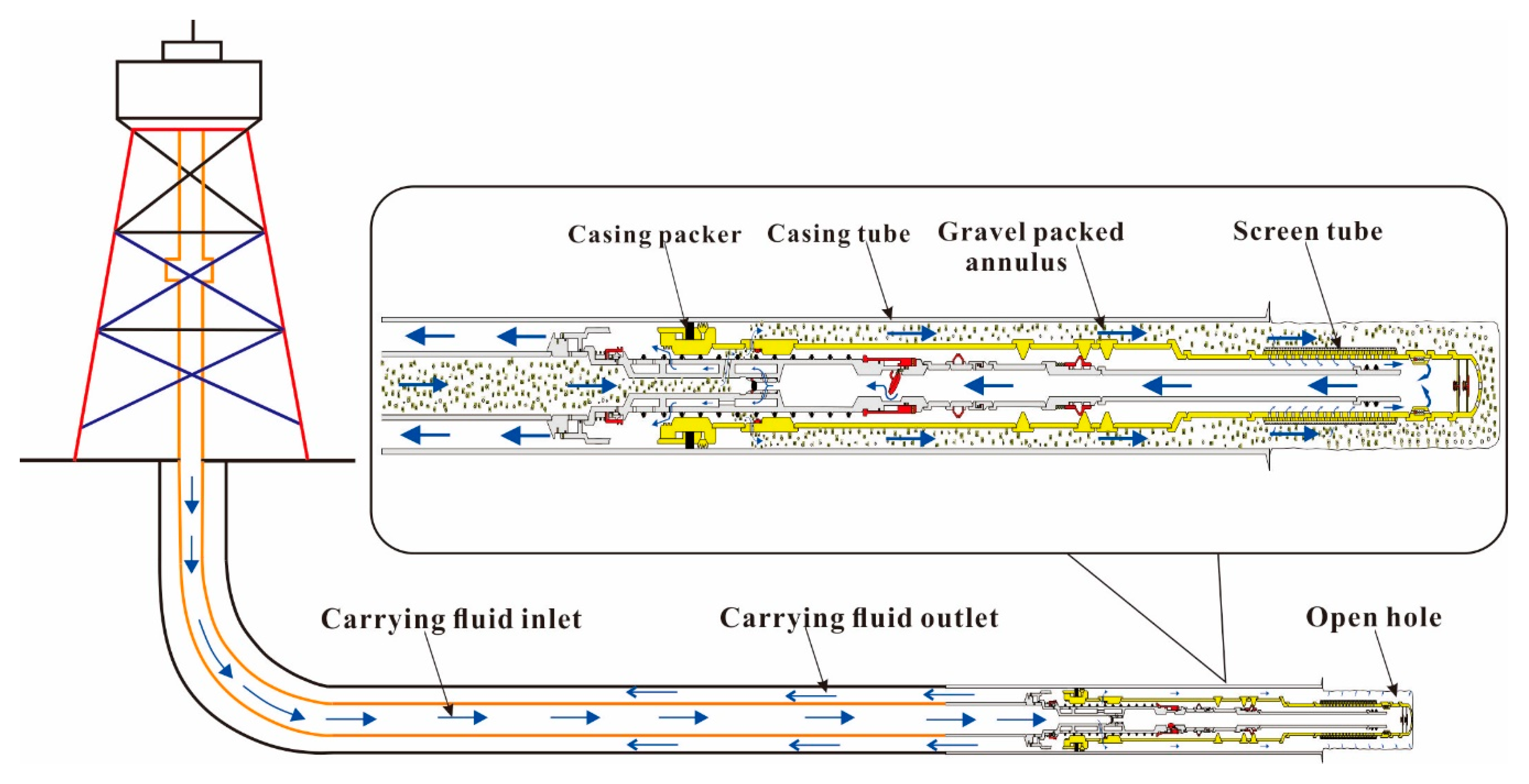
2. Pulsed Gravel Packing Numerical Model

2.1. Solid-Liquid Two-Phase Flow Governing Equation

Based on the Eulerian–Eulerian model [27], pulsed gravel packing in horizontal wells is studied in this paper. The model assumes that liquid phase and solid phase are continuous, the density of liquid phase and solid phase is constant, and there is no mass transfer. The continuity equation can be expressed as follows [28,29]:
Liquid   phase t ( ε 1 ρ 1 ) + ( ε 1 ρ 1 v 1 ) = 0
Solid   phase t ( ε s ρ s ) + ( ε s ρ s v s ) = 0
where εl, εs represent the concentration of the liquid phase and solid phase, dimensionless; ρl, ρs represent the density of liquid phase and solid phase, kg/m3; and v l , v s represent the velocity of the liquid phase and solid phase, m/s.
Assuming that there is no mass exchange between the solid phase and the liquid phase, the momentum governing equations can be obtained as follows [30]:
Liquid   phase t ( ε 1 ρ 1 v 1 ) + ( ε 1 ρ 1 v 1 v 1 ) = ε 1 τ ¯ ¯ 1 + ε 1 ρ 1 g ε 1 p l + β ( v 1 v s )
Solid   phase t ( ε s ρ s v s ) + ( ε α ρ s v s v s ) = ε s τ ¯ ¯ s + ε s ρ s g ε s p s β ( v 1 v s )
The liquid phase stress tensor τ ¯ ¯ 1 was determined using Equation (5):
τ ¯ ¯ 1 = μ 1 [ v 1 + ( v 1 ) T ] 2 / 3 μ 1 ( v 1 ) I
The solid phase stress tensor τ ¯ ¯ s was determined using Equation (6):
τ ¯ ¯ s = ( p s + ξ s v s ) I + μ s { [ v s + ( v s ) T ] 2 3 ( v s ) I }
where g is the acceleration of gravity, m/s2; pl is the liquid phase pressure, MPa; ps is the solid phase pressure, MPa; β is the drag force coefficient between liquid phase and solid phase, dimensionless; μl is the shear viscosity of liquid phase, Pa·s; μs is the shear viscosity of solid phase, Pa·s; ξs is the dynamic viscosity of solid phase, Pa·s; and I is the unit vector.
In this paper, the turbulence model is the RNG k-ε model [31,32]. The transport equations of the turbulent kinetic energy k and turbulence dissipation rate ε in the turbulence model can be expressed as follows [33,34]:
ρ m k t + ρ m ( ν m k ) = ( ( μ m + μ t , m σ k RNG ) k ) + G k , m ρ m ε
ρ m ε t + ρ m ( ν m ε ) = ( ( μ m + μ t , m σ ε RNG ) ε ) + C 1 ε RNG G k , m ε k ρ m C 2 ε RNG ε 2 k
ρ m = i = 1 N α i ρ i
μ m = i = 1 n α i μ i
ν m = i = 1 N α i ρ i v i i = 1 N α i ρ i
μ t , m = C μ RNG ρ m k 2 / ε
G k , m = μ t , m ( ν m + ( ν m ) T ) : ν m
C 1 ε RNG = 1.42 f η
f η = η ( 1 η 4.38 ) ( 1 + β RNG η 3 )
η = G k , m ρ m C μ RNG ε
where k is turbulent kinetic energy, m2/s2; ε is the dissipation rate of turbulent kinetic energy, m2/s2; ρm is the mixed density of two phases, kg/m3; ρi is the density of phase i, kg/m3; νm is the mixed velocity of two phases, m/s; νi is the velocity of phase i, m/s; αi is the volume fraction of phase i, dimensionless; μm is the mixed dynamic viscosity of two phases, Pa·s; μt,m is the mixed turbulent viscosity of two phases, Pa·s; Gk,m is the increment of turbulent kinetic energy caused by the average velocity gradient; C1εRNG is the turbulent kinetic energy coefficient, dimensionless; and the constants in the equation as follows: CμRNG = 0.085, C2εRNG = 1.68, σkRNG = 0.7179, σεRNG = 0.7179, βRNG = 0.012.

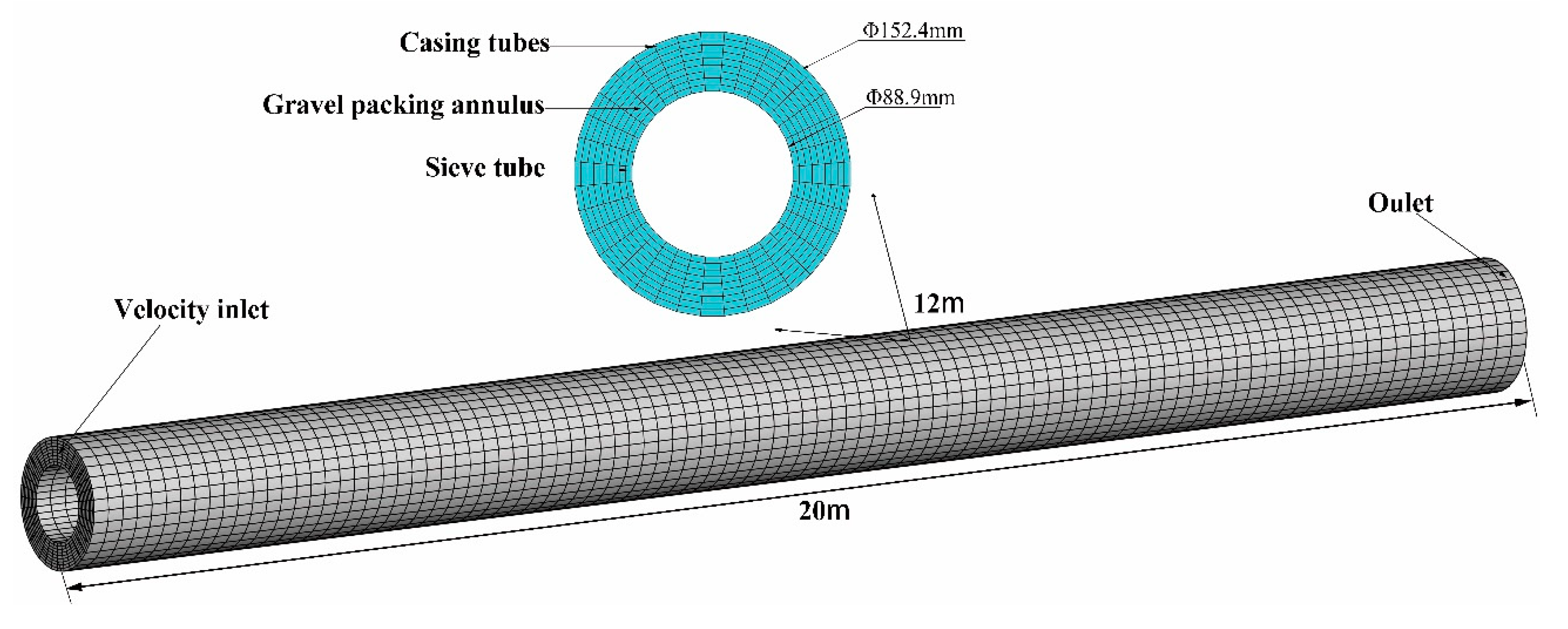
2.2. Physical Models and Boundary Conditions

During the pulsed gravel packing process in horizontal wells, the sand-carrying fluid is transported to the horizontal section of the wellbore through the pipe string [35]. When the sand-carrying fluid enters the annulus of the casing and sand control string, the gravel is gradually transported and deposited in the annulus, while the fluid is returned to the sand control string through the screen tube. The function of the screen tube is to prevent gravel from entering the sand control string, so that the gravel is deposited in the annulus, and to prevent sand in the formation from entering the wellbore during the production process of the oil well. A physical model was established for the gravel packing process of horizontal wells, as shown in Figure 1.
By simplifying the physical model of the gravel packing process in horizontal wells, a finite element numerical model was established for the horizontal well section. The string diameter was 88.9 mm, the borehole diameter was 152.4 mm, and the model length was 20 m. The model is shown in Figure 2:
In order to ensure the convergence and stability of the calculation results, the following assumptions were made for the boundary conditions of the numerical model:
(1) Velocity inlet boundary was adopted and the user-defined function (UDF) was introduced to realize the change of pulse waveform. At the same time, the influences of annulus temperature and bottom hole gas and water seepage on the flow of sand-carrying fluid were ignored, and the sand-carrying fluid was regarded as the incompressible fluid [36].
(2) The outlet boundary adopted the pressure boundary, and the boundary pressure value was consistent with the environmental pressure.
(3) The string and wellbore were assumed to be smooth without slip boundary, and the gravel diameter and density were the same in any wellbore section.

3. Parameter Analysis of Pulsed Gravel Packing

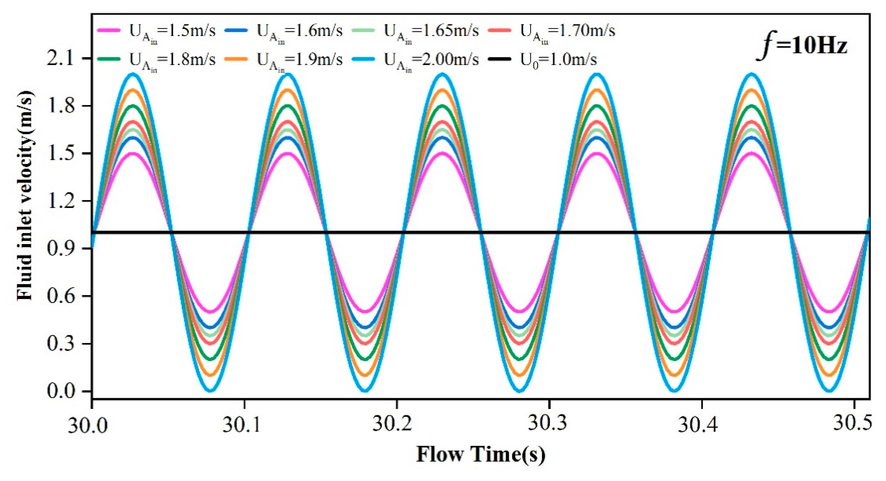
3.1. Optimization of Pulsed Gravel Packing Parameters

In Fluent software, the sinusoidal pulse waveform was defined by embedding the UDF program to change the inlet boundary velocity. According to the theory of sinusoidal pulse wave, the frequency range of the selected pulse waveform is 2.5–10 Hz, the amplitude range is 1.5–2.0 m/s. Numerical simulation is carried out by combination of frequency and amplitude, where the simulation time is 60 s, the average amplitude is 1 m/s, the initial sand-carrying ratio is 10%, the gravel diameter is 1 mm, the sand-carrying fluid viscosity is 1.0 mPa·s, and the eccentricity of the string is 0. The evaluation criteria were fixed bed volume fraction and gravel migration velocity. Pulse waveforms with different amplitudes and frequencies are shown in Figure 3 and Figure 4, respectively.
In the pulsed gravel packing process of horizontal wells, three layers of hydraulic flow may occur in annular flow field, which are fixed bed, moving bed, and suspended bed as shown in Figure 5.

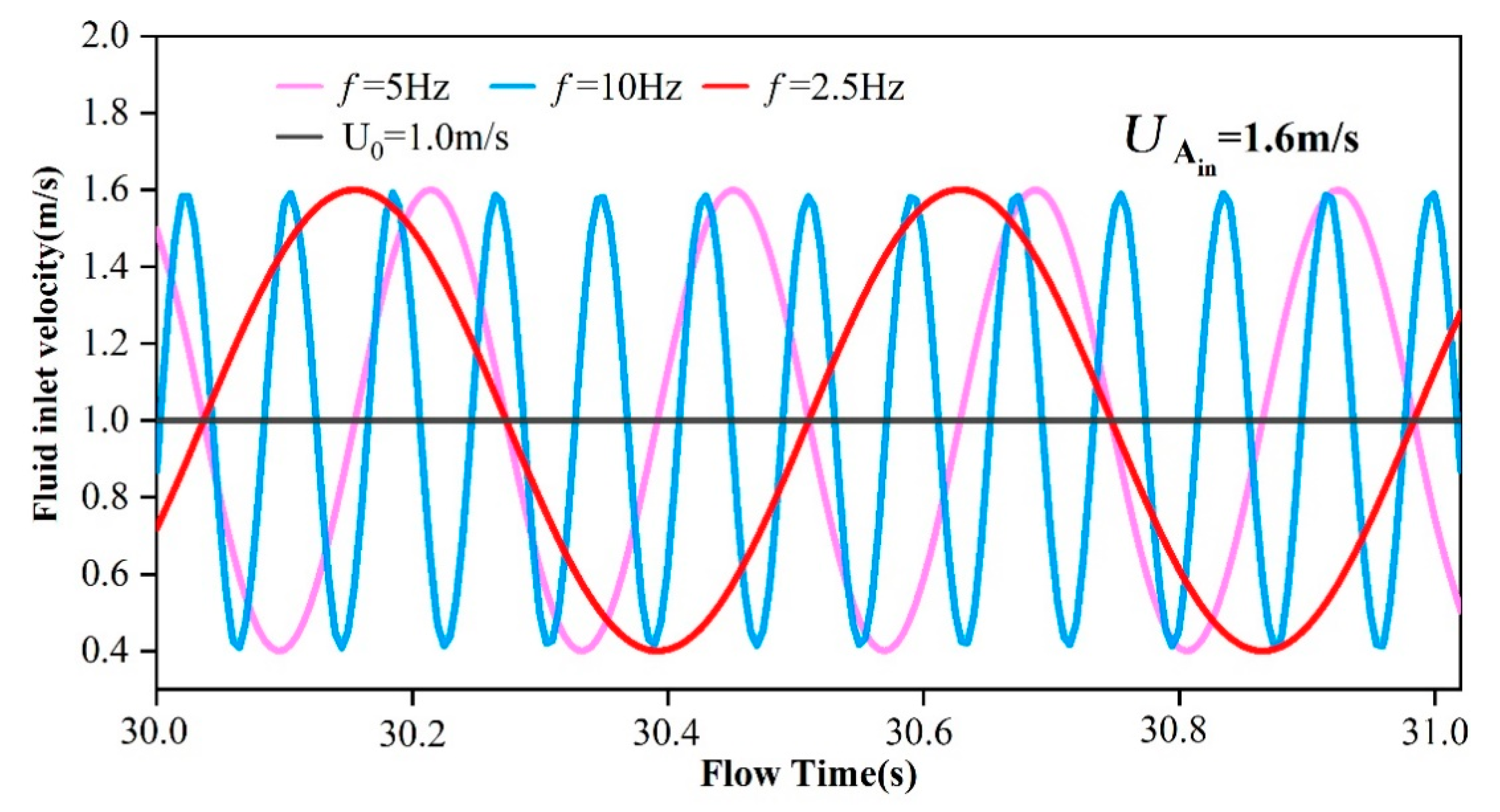
3.2. Optimal Analysis of Pulsed Gravel Packing Waveform in Horizontal Wells

The numerical simulation of pulsed gravel packing horizontal wells was carried out, with the frequency range of pulse waveform 2.5–10 Hz and the amplitude range 1.5–2.0 m/s. The results are shown in Figure 6. When the frequency was 10 Hz, the volume fraction of the fixed bed increased from 2.78% to 11.85% with the increase of amplitude. When the frequency was 5 Hz, the volume fraction of fixed bed decreased first and then increased with the increase of amplitude, in which the minimum value was 1.14% and the maximum value was 8.77%. When the frequency was 2.5 Hz, the volume fraction of the fixed bed also decreased first and then increased with the increase of amplitude, in which the minimum volume fraction was 2.06% and the maximum volume fraction was 9.35%. Through comparative analysis, it was found that when the frequency was 5 Hz and the amplitude was 1.65 m/s, the volume fraction of the fixed bed was the smallest and its value was 1.14%. Under this combination of frequency and amplitude, the sand-carrying fluid not only had strong sand-carrying performance but also had the best effect of reducing the volume fraction of fixed bed. Therefore, the pulsed gravel packing method has less risk and higher filling efficiency during the packing process.

3.3. Comparative Analysis of Pulsed Gravel Packing and Conventional Gravel Packing in Horizontal Wells

When the transport law of pulsed gravel packing and conventional gravel packing in horizontal wells was compared, the optimized pulse waveform parameters were added to the inlet boundary, and other influencing factors were consistent with conventional gravel packing. Gravel migration velocity and gravel volume fraction were used as evaluation indexes. In order to explain the gravel migration for horizontal wells in detail, sections were established at 3 m, 5 m, 7 m, 10 m, 15 m, and 17 m from the inlet. These sections were roughly evenly distributed in the annular flow, which can effectively reflect the numerical simulation results. At the same time, we extracted the volume fraction and migration velocity of pulsed gravel packing and conventional gravel packing in horizontal wells at different locations at the time of 30 s, with results as shown in Figure 7, Figure 8 and Figure 9. Under the same conditions, the volume fraction of fixed bed and moving bed with pulsed gravel packing in horizontal wells was smaller than that of conventional gravel packing, while the volume fraction of suspended bed was larger than that of conventional gravel packing. The gravel transport velocity of pulsed gravel packing in horizontal wells was faster. At the position of section 15 m, the volume fractions of fixed, mobile, and suspended beds with conventional gravel packing were 9.24%, 22.2%, and 68.56%, respectively. The volume fractions of the fixed bed, moving bed, and suspended bed with pulsed gravel packing were 5.35%, 16.1%, 78.55%, respectively. It can be seen that the fixed bed volume fraction and moving bed volume fraction of pulsed gravel packing in horizontal wells decreased by 42.1% and 27.5%, respectively, and the suspended bed volume fraction increased by 14.5%.

4. Analysis of Influencing Factors for the Pulsed Gravel Packing

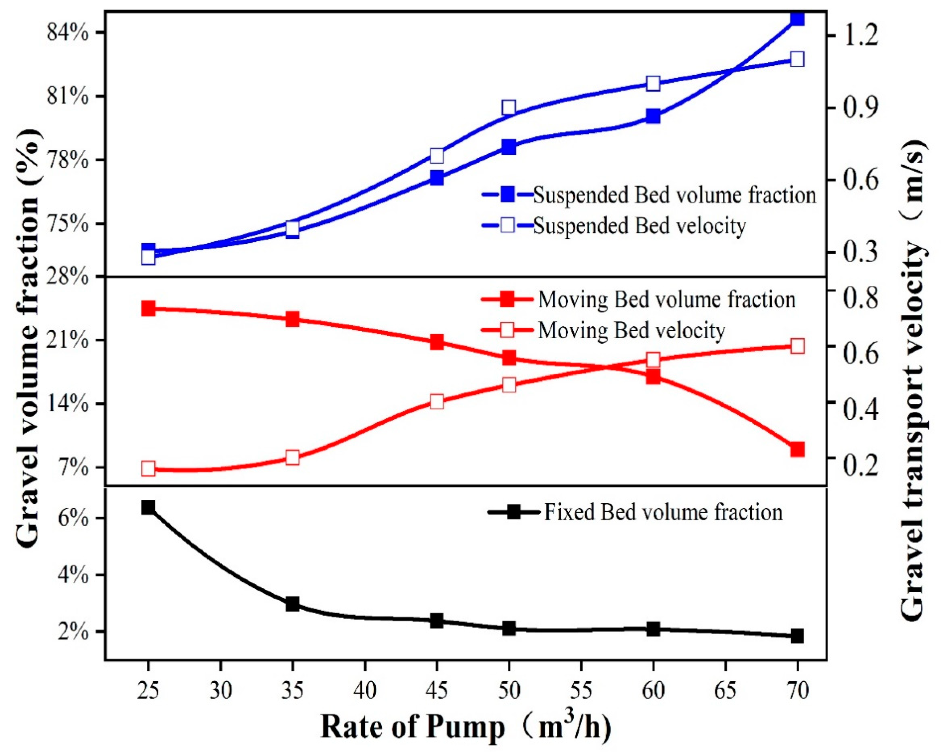
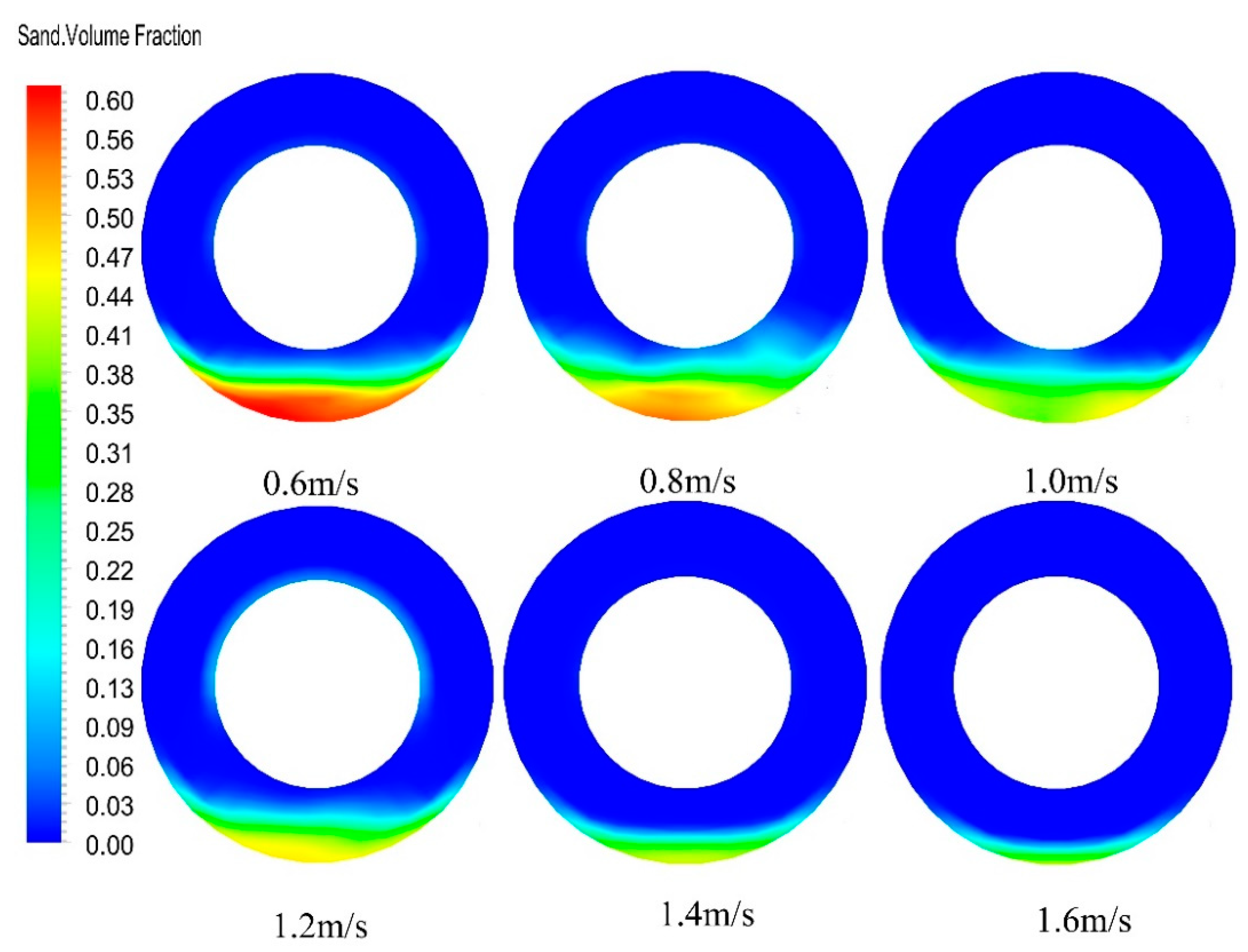
4.1. Impact of Displacement on Pulsed Gravel Packing in Horizontal Wells

The optimized sinusoidal pulse waveform was added to the inlet boundary to make the inlet displacement changes in pulse, and the influence of average inlet displacement from 25 m3/h to 70 m3/h on gravel migration and volume fraction was studied. At 30 s, the volume fraction and velocity of the section at a distance of 10 m from the inlet was extracted, and the results are shown in Figure 10 and Figure 11. It can be seen from Figure 10 that, with the increase of displacement, the volume fraction of fixed bed decreased from 6.38% to 1.83%, when the displacement reached 50 m3/h, the reduction trend of fixed bed volume fraction tended to be flat. The volume fraction of the mobile bed also decreased gradually with the increase of displacement, and when the displacement reached 60 m3/h, the reduction trend of the volume fraction of the mobile bed increased. The volume fraction of the floating bed increased rapidly with the increase of displacement. The results indicate that with the increase of displacement, the gravel migration ability increased, and after the displacement reached a certain critical value, the gravel migration ability increased slowly.

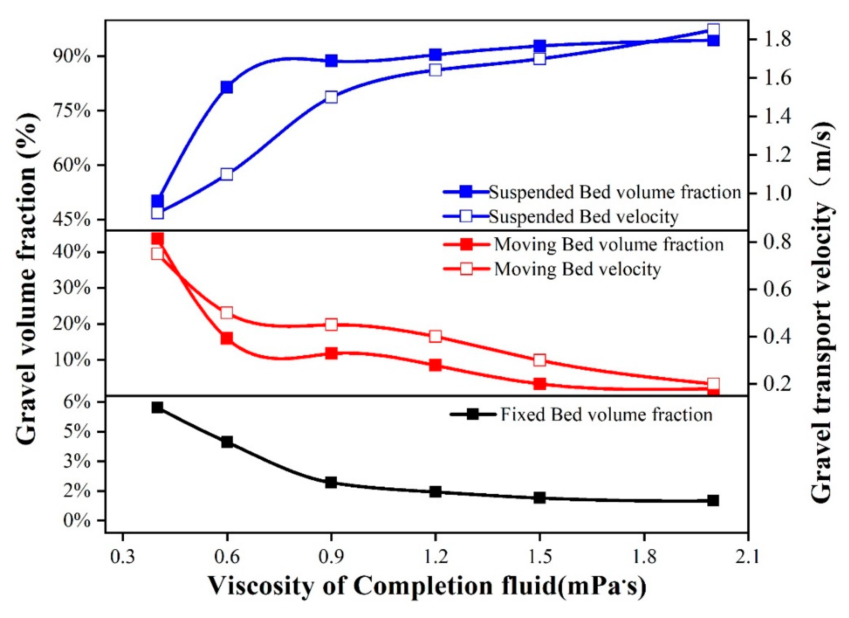
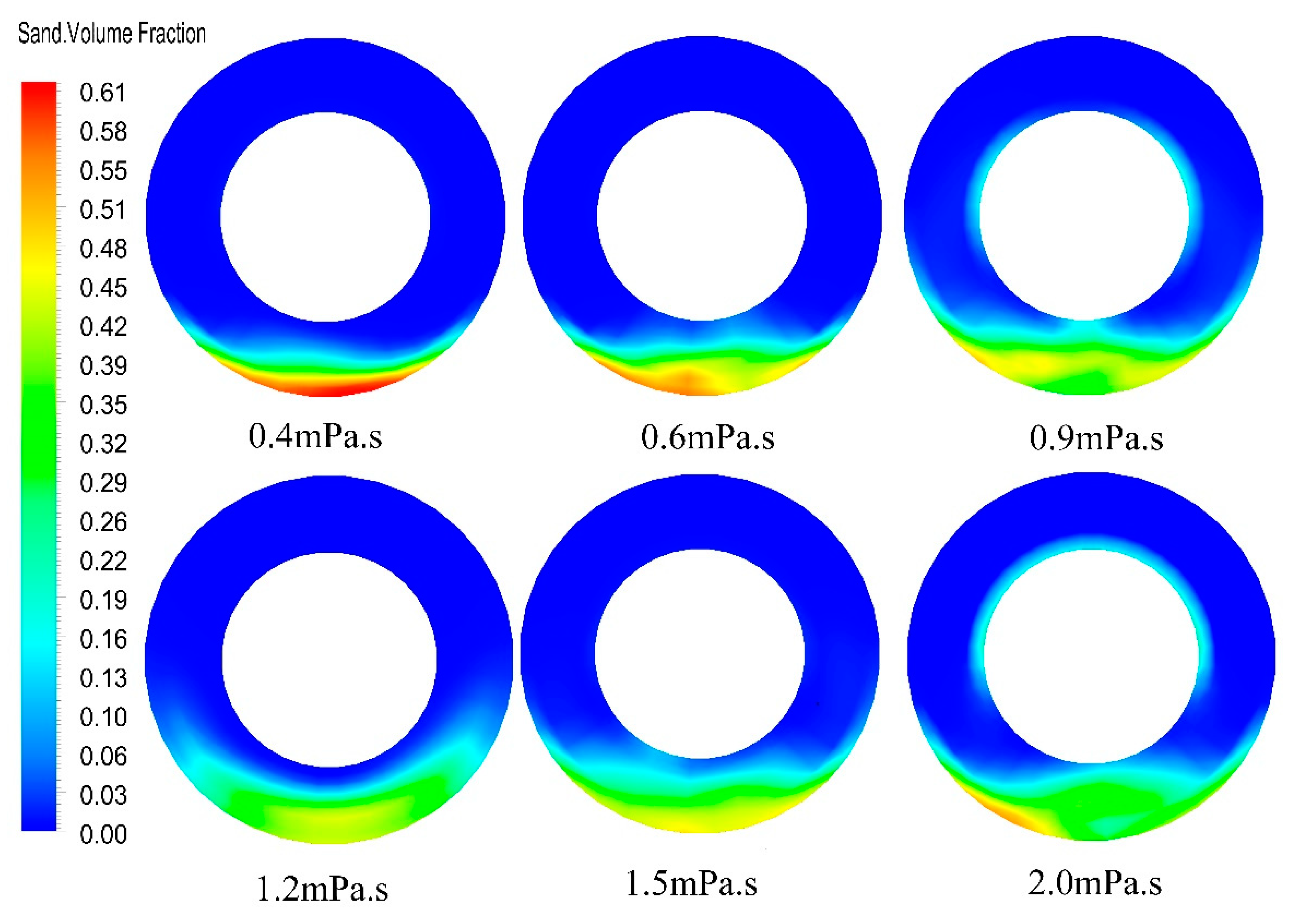
4.2. Impact of the Viscosity of the Carrying Fluid on Pulsed Gravel Packing in Horizontal Wells

The optimized sinusoidal pulse waveform was added to the inlet boundary to make the inlet displacement changes in pulse and to study the effect of viscosity change of sand-carrying fluid on gravel migration and volume fraction. At 30 s, we extracted the volume fraction and velocity of the section at a distance of 10 m from the inlet, and the results are shown in Figure 12 and Figure 13. It can be seen from Figure 12, with the increase of the viscosity of the sand-carrying fluid, the volume fraction of the fixed bed gradually decreased, and when the viscosity of the sand-carrying fluid was greater than 0.9 MPa·s, the reduction trend of the volume fraction of the fixed bed was gentle. The volume fraction of the moving bed gradually decreased with the increase of the viscosity of the sand-carrying fluid, and when the viscosity of the sand-carrying fluid was greater than 0.6 MPa·s, the decreasing trend of the volume fraction of the moving bed was gentle. The volume fraction of the suspended bed increased from 50% to 92% with the increase of the viscosity of the sand-carrying fluid, and the increase rate was the highest when the viscosity of the sand-carrying fluid was 0.6 MPa·s. The velocity of the moving bed and suspended bed also increased with the increasing of the viscosity of the sand-carrying fluid. The study shows that the viscosity of the carrier fluid increased, the energy obtained by a single gravel increased, and the transportability of gravel increased. When the viscosity of sand-carrying fluid reached a certain critical value, the improvement of gravel transportability was relatively slow.

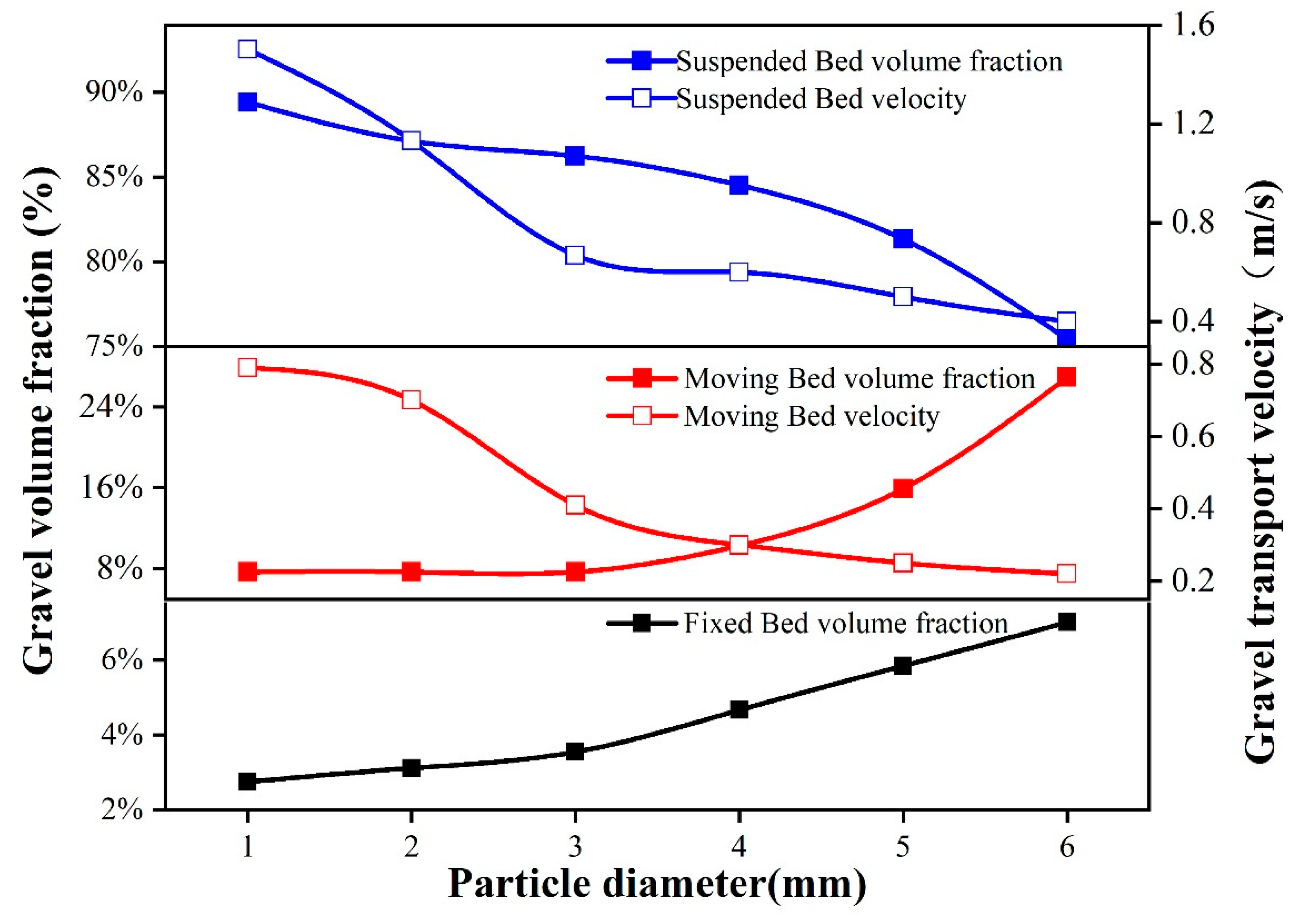
4.3. Impact of Particle Size on Pulsed Gravel Packing in Horizontal Wells

The optimized sinusoidal pulse waveform was added to the inlet boundary to make the inlet displacement changes in pulse and to study the effect of particle size on gravel migration and volume fraction. At 30 s, extracting the volume fraction and velocity of the section at a distance of 10 m from the inlet, and the results were shown in Figure 14 and Figure 15. It can be seen from Figure 14 that, with the increase of gravel diameter, the volume fraction of the fixed bed and moving bed showed an increasing trend. The fixed bed volume fraction reached the minimum value of 2.74% when the gravel diameter was 1 mm, and the maximum value of 7.10% when the gravel diameter was 6 mm. With the increase of gravel diameter, the mobile bed volume fraction increased from 8.2% to 28%. The volume fraction of the suspended bed decreased rapidly with the increase of gravel diameter from 86% to 75%. The above results show that as the gravel diameter increased, the mass of the single gravel increased, and the energy required for the gravel transition from the static state to the mobile state increased. As the displacement of the sand-carrying fluid did not change, with the increase of gravel diameter, there was insufficient energy for the gravel to move forward. Therefore, the migration velocity of the suspended bed and the moving bed decreased obviously, which is not conducive to gravel migration.

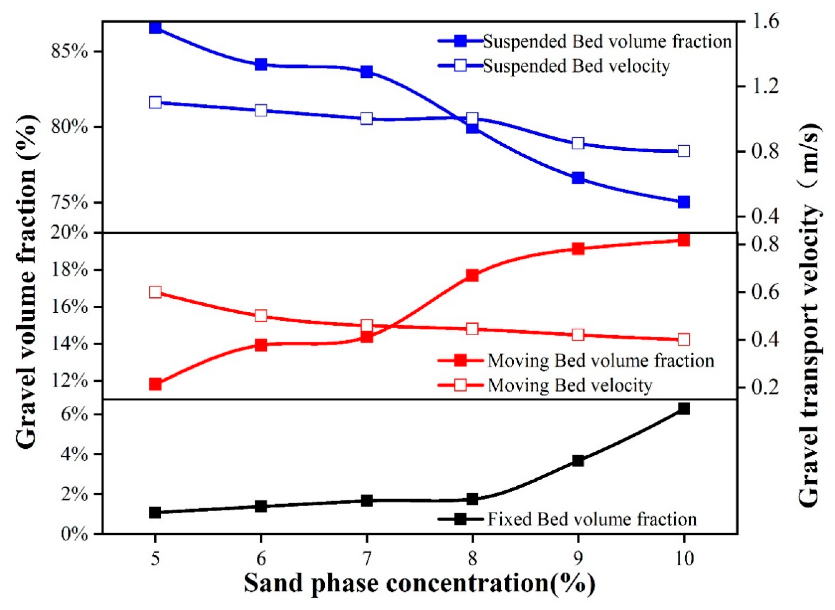
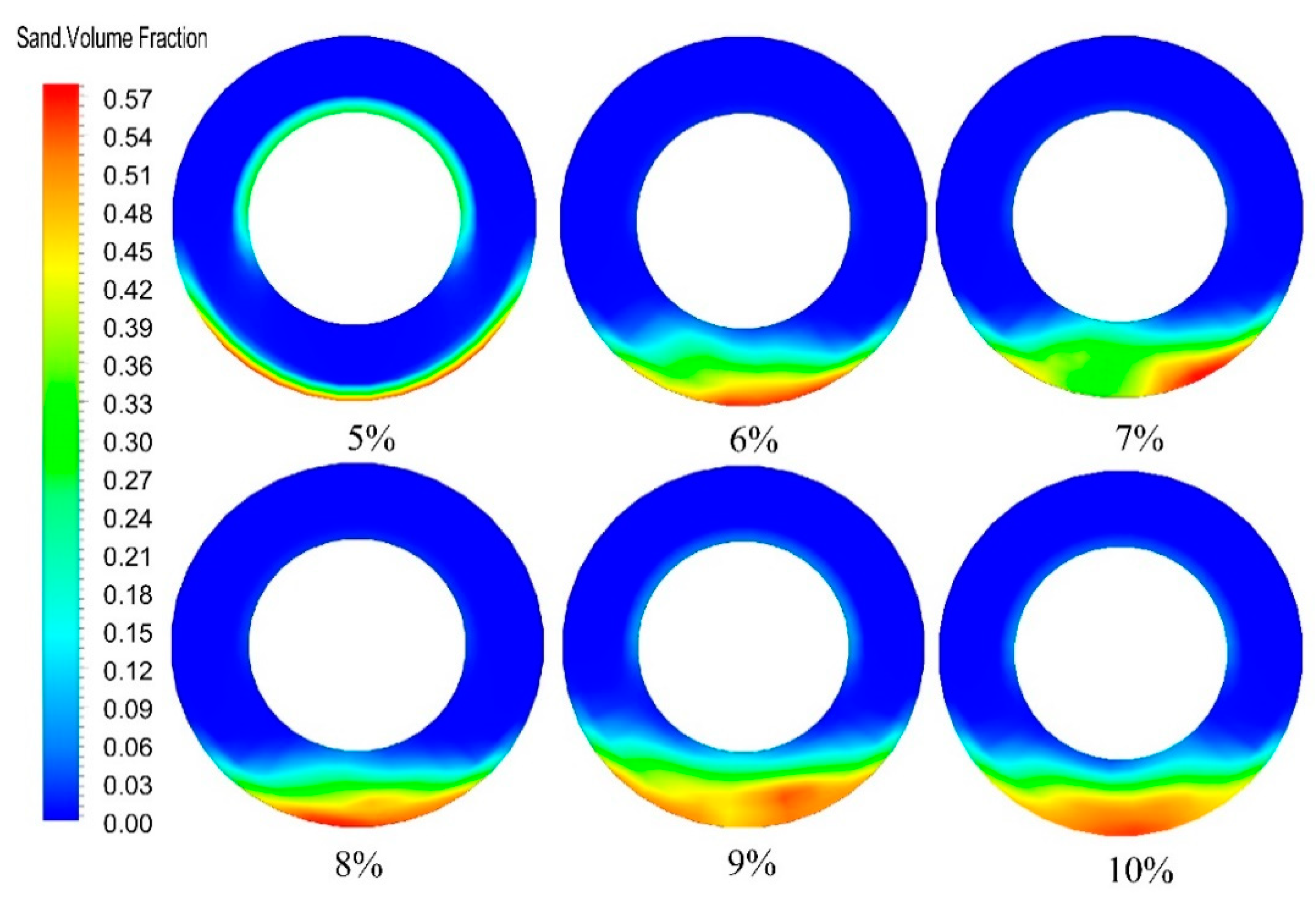
4.4. Impact of Sand Carrying Ratio on Pulsed Gravel Packing in Horizontal Wells

The optimized sinusoidal pulse waveform was added to the inlet boundary to make the inlet displacement changes in pulse and to study the effect of sand carrying ratio on gravel migration and volume fraction. At 30 s, we extracted the volume fraction and velocity of the section at a distance of 10 m from the inlet, and the results are shown in Figure 16 and Figure 17. It can be seen from Figure 16 that, with the increase of the sand carrying ratio, the volume fraction of the fixed bed increased from 1.6% to 6.3%, and when the sand carrying ratio reached 8%, the volume fraction increased significantly. The volume fraction of the moving bed increased from 12% to 19.5% with the increase of the carrying ratio, and the increase rate of the volume fraction increased significantly when the carrying ratio reached 7%. The volume fraction of the suspended bed decreased with the increase of the carrying ratio, and the rate of decrease increased when the carrying ratio was 7%. The transport velocity of moving bed and suspended bed decreased with the increase of sand carrying ratio. The above results show that with the increasing of the carrying ratio, the volume fraction of the moving bed and the fixed bed increased continuously, while the volume fraction of the suspended bed decreased continuously, and the transport velocity of the moving bed and the suspended bed decreased continuously. Therefore, it is necessary to strictly control the carrying ratio during pulsed gravel packing in horizontal wells.

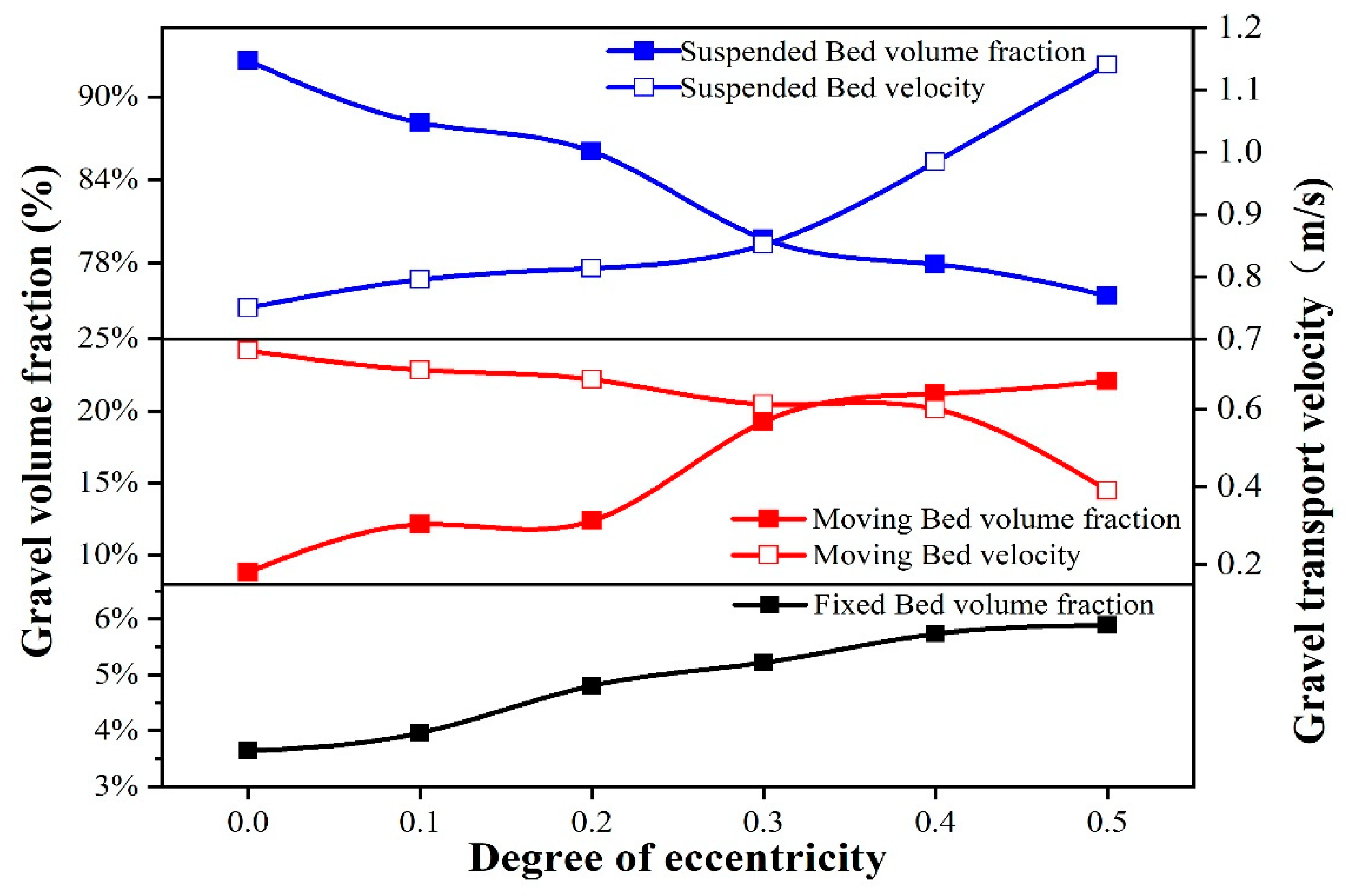
4.5. Impact of String Eccentricity on Pulsed Gravel Packing in Horizontal Wells

The optimized sinusoidal pulse waveform was added to the inlet boundary to make the inlet displacement changes in pulse and to study the effect of string eccentricity on gravel migration and volume fraction. At 30 s, we extracted the volume fraction and velocity of the section at a distance of 10 m from the inlet, and the results are shown in Figure 18 and Figure 19. It can be seen from Figure 18 that, as the eccentricity of the string increased, the volume fraction of the fixed bed gradually increased, and when the eccentricity of the string was 0.5, the maximum value of the volume fraction of the fixed bed was 5.70%. The volume fraction of the moving bed increased gradually with the eccentricity of the string increasing, and the maximum value was 22.5%. The volume fraction of the suspended bed decreased with the increase of the eccentricity of the string. The results show that with the increase of the eccentricity of the string, the volume fraction of fixed bed and moving bed increased, the volume fraction of suspended bed decreased continuously, the migration velocity of moving bed decreased continuously, and the migration ability of gravel decreased.

5. Conclusions

(1) By optimizing the pulsed gravel packing waveform of the horizontal well, the best sinusoidal pulse waveform was obtained, in which the frequency was 5 Hz and the amplitude was 1.65 m/s. Under this frequency and amplitude, the sand-carrying fluid has good sand-carrying performance and the best effect of reducing the volume fraction of the fixed bed, and the risk of plugging during the filling process is small and the filling efficiency is high.
(2) A comparative analysis of the results of pulsed gravel packing and conventional gravel packing in horizontal wells shows that pulsed gravel packing is more efficient than conventional gravel packing. Pulsed gravel packing has a better effect in reducing sand bed height and lengthening gravel migration distance.
(3) By analyzing the influences of the carrying fluid displacement, the carrying fluid viscosity, the gravel diameter, the carrying ratio, and the string eccentricity on the pulsed gravel packing in horizontal wells, the distribution rules of the gravel transport velocity and the volume fraction were obtained. In the process of pulsed gravel packing in horizontal wells, with the increase of displacement and viscosity of the sand-carrying fluid, the volume fraction of fixed bed and moving bed decreases gradually, while the volume fraction of suspended bed increases gradually, and the gravel transport velocity is improved. With the increase of gravel particle size, sand carrying ratio, and string eccentricity, the volume fraction of fixed bed and moving bed gradually increase, while that of suspended bed gradually decreases, and when the gravel diameter is greater than 3 mm and the sand carrying ratio is greater than 8%, the volume fraction of fixed bed rapidly increases, which may lead to the over-high sand bed. The string eccentricity has a great influence on pulsed gravel packing in horizontal wells, so it is necessary to avoid pipe eccentricity during the operation.
(4) In order to verify the feasibility of the pulsed gravel packing technology for horizontal wells proposed in this paper, laboratory experiments will be carried out for further verification and, at the same time, field application will be carried out to improve gravel packing efficiency of horizontal wells.

Author Contributions

Conceptualization, J.Y., S.C., and Q.O.; data curation, Y.Z.; supervision, X.Q. and Y.G.; writing–original draft, Z.Z. All authors have read and agreed to the published version of the manuscript.

Funding

This work has been supported by the Natural Science Foundation of China (NSFC: No. 51434009 and No. 51774301), the major projects of National Science and Technology (No. 2016ZX05024005) and China Scholarship Council (CSC).

Conflicts of Interest

The authors declare no conflict of interest.

References

  1. Joshi, S.D. Cost/Benefits of Horizontal Wells. In Proceedings of the SPE Western Regional/AAPG Pacific Section Joint Meeting, Long Beach, CA, USA, 19–24 May 2003; p. 9. [Google Scholar]
  2. Alekperov, V.Y.; Lyashko, N.N.; Gavura, A.V.; Fedotov, I.B.; Kibalenko, I.A. Application of horizontal wells to accelerate commissioning of wells and to increase development efficiency of offshore oil and gas fields in the Northern Caspian (Russian). Oil Ind. J. 2018, 2018, 72–76. [Google Scholar] [CrossRef]
  3. Ali, S.A.; Grigsby, T.F.; Vitthal, S. Advances in Horizontal Openhole Gravel Packing. SPE Drill. Complet. 2006, 21, 23–31. [Google Scholar] [CrossRef]
  4. Parlar, M.; Albino, E.H. Challenges, Accomplishments, and Recent Developments in Gravel Packing. J. Pet. Technol. 2000, 52, 50–58. [Google Scholar] [CrossRef]
  5. Forrest, J.K. Horizontal Gravel Packing Studies in a Full-Scale Model Wellbore. In Proceedings of the SPE Annual Technical Conference and Exhibition, New Orleans, LA, USA, 23–26 September 1990; p. 9. [Google Scholar]
  6. Maly, G.P.; Robinson, J.P.; Laurie, A.M. New Gravel Pack Tool for Improving Pack Placement. J. Pet. Technol. 1974, 26, 19–24. [Google Scholar] [CrossRef]
  7. Doron, P.; Granica, D.; Barnea, D. Slurry flow in horizontal pipes—experimental and modeling. Int. J. Multiph. Flow 1987, 13, 535–547. [Google Scholar] [CrossRef]
  8. Doron, P.; Barnea, D. Effect of the no-slip assumption on the prediction of solid-liquid flow characteristics. Int. J. Multiph. Flow 1992, 18, 617–622. [Google Scholar] [CrossRef]
  9. Doron, P.; Barnea, D. A three-layer model for solid-liquid flow in horizontal pipes. Int. J. Multiph. Flow 1993, 19, 1029–1043. [Google Scholar] [CrossRef]
  10. Gruesbeck, C.; Salathiel, W.M.; Echols, E.E. Design of Gravel Packs in Deviated Wellbores. J. Pet. Technol. 1979, 31, 109–115. [Google Scholar] [CrossRef]
  11. Peden, J.M.; Russell, J.; Oyeneyin, M.B. The Design and Optimisation of Gravel Packing Operations in Deviated Wells. In Proceedings of the European Petroleum Conference, London, UK, 22–25 October 1984; p. 22. [Google Scholar]
  12. Peden, J.M.; Russell, J.; Oyeneyin, M.B. A Numerical Approach to the Design of a Gravel Pack for Effective Sand Control in Deviated Wells. In Proceedings of the SPE Annual Technical Conference and Exhibition, Houston, TX, USA, 16–19 September 1984; p. 15. [Google Scholar]
  13. Peden, J.M.; Russell, J.; Oyeneyin, M.B. Design of an Effective Gravel Pack for Sand Control: A Numerical Approach. In Proceedings of the SPE California Regional Meeting, Bakersfield, CA, USA, 27–29 March 1985; p. 14. [Google Scholar]
  14. Wahlmeier, M.A.; Andrews, P.W. Mechanics of Gravel Placement and Packing: A Design and Evaluation Approach. SPE Prod. Eng. 1988, 3, 69–82. [Google Scholar] [CrossRef]
  15. Chen, Z. Horizontal Well Gravel Packing: Dynamic Alpha Wave Dune Height Calculation and Its Impact on Gravel Placement Job Execution. In Proceedings of the SPE Annual Technical Conference and Exhibition, Anaheim, CA, USA, 11–14 November 2007; p. 10. [Google Scholar]
  16. Penberthy, W.L., Jr.; Bickham, K.L.; Nguyen, H.T.; Paulley, T.A. Gravel Placement in Horizontal Wells. SPE Drill. Complet. 1997, 12, 85–92. [Google Scholar] [CrossRef]
  17. Penberthy, W.L., Jr. Gravel Placement Through Perforations and Perforation Cleaning for Gravel Packing. J. Pet. Technol. 1988, 40, 229–236. [Google Scholar] [CrossRef]
  18. Osisanya, S.O.; Ayeni, K.B.; Osisanya, K.P. Factors Affecting Horizontal Well Gravel-Pack Efficiency. In Proceedings of the SPE Annual Technical Conference and Exhibition, San Antonio, TX, USA, 24–27 September 2006; p. 7. [Google Scholar]
  19. Nguyen, P.D.; Fitzpatrick, H.J.; Woodbridge, G.A.; Reidenbach, V.G. Analysis of Gravel Packing Using 3-D Numerical Simulation. In Proceedings of the SPE Formation Damage Control Symposium, Lafayette, LA, USA, 26–27 February 1992; p. 12. [Google Scholar]
  20. Martins, A.L.; Magalhaes, J.V.M.; Calderon, A.; Chagas, C.M. A Mechanistic Model for Horizontal Gravel Pack Displacement. SPE J. 2005, 10, 229–237. [Google Scholar] [CrossRef]
  21. Pu, C.S. A New Intelligent Computer System for Horizontal Wells Gravel-Packing. In Proceedings of the International Conference on Horizontal Well Technology, Calgary, AB, Canada, 18–20 November 1996; p. 8. [Google Scholar]
  22. Ojo, K.P.; Osisanya, S.O.; Ayeni, K.B. Development of a 3D Numerical Simulator of Horizontal Well Gravel Pack. In Proceedings of the Canadian International Petroleum Conference, Calgary, AB, Canada, 13–15 June 2006; p. 14. [Google Scholar]
  23. Ojo, K.P.; Osisanya, S.O.; Ayeni, K. Factors Affecting Horizontal Well Gravel Pack Efficiency. J. Can. Pet. Technol. 2008, 47, 50–54. [Google Scholar] [CrossRef]
  24. Changyin, D.; Jiajia, L.; Yanlong, L.; Huaiwen, L.; Lifei, S. Experimental and Visual Simulation of Gravel Packing in Horizontal and Highly Deviated Wells. In Proceedings of the SPE Latin America and Caribbean Petroleum Engineering Conference, Maracaibo, Venezuela, 21–23 May 2014; p. 13. [Google Scholar]
  25. Dong, C.Y.; Gao, K.G.; Dong, S.X.; Shang, X.S.; Wu, Y.X.; Zhong, Y.X. A new integrated method for comprehensive performance of mechanical sand control screens testing and evaluation. J. Pet. Sci. Eng. 2017, 158, 775–783. [Google Scholar] [CrossRef]
  26. Dong, C.Y.; Zhou, Y.G.; Chen, Q.; Zhu, C.M.; Li, Y.L.; Li, X.B.; Liu, Y.B. Effects of fluid flow rate and viscosity on gravel-pack plugging and the optimization of sand-control wells production. Pet. Explor. Dev. 2019, 46, 1251–1259. [Google Scholar] [CrossRef]
  27. Adamczyk, W.P.; Klimanek, A.; Białecki, R.A.; Węcel, G.; Kozołub, P.; Czakiert, T. Comparison of the standard Euler–Euler and hybrid Euler–Lagrange approaches for modeling particle transport in a pilot-scale circulating fluidized bed. Particuology 2014, 15, 129–137. [Google Scholar] [CrossRef]
  28. Pang, B.X.; Wang, S.Y.; Liu, G.D.; Jiang, X.X.; Lu, H.L.; Li, Z.J. Numerical prediction of flow behavior of cuttings carried by Herschel-Bulkley fluids in horizontal well using kinetic theory of granular flow. Powder Technol. 2018, 329, 386–398. [Google Scholar] [CrossRef]
  29. Ravnik, J.; Škerget, L.; Hriberšek, M. The wavelet transform for BEM computational fluid dynamics. Eng. Anal. Bound. Elem. 2004, 28, 1303–1314. [Google Scholar] [CrossRef]
  30. Wodołażski, A.; Skiba, J.; Zarębska, K.; Polański, J.; Smolinski, A. CFD Modeling of the Catalyst Oil Slurry Hydrodynamics in a High Pressure and Temperature as Potential for Biomass Liquefaction. Energies 2020, 13, 5694. [Google Scholar] [CrossRef]
  31. Ofei, T.; Irawan, S.; Pao, W. CFD Method for Predicting Annular Pressure Losses and Cuttings Concentration in Eccentric Horizontal Wells. J. Pet. Eng. 2014, 2014, 1–16. [Google Scholar] [CrossRef] [Green Version]
  32. Argyropoulos, C.D.; Markatos, N.C. Recent advances on the numerical modelling of turbulent flows. Appl. Math. Model. 2015, 39, 693–732. [Google Scholar] [CrossRef]
  33. Costamte, Y.R.; Trondsen, A.; Bergkvam, R.M.; Hodne, H.; Saasen, A. Horizontal Openhole Gravel Packing in Wells With Long Blank Pipe and Screen Sections. In Proceedings of the SPE Deepwater Drilling and Completions Conference, Galveston, TX, USA, 20–21 June 2010; p. 21. [Google Scholar]
  34. Vaziri, E.; Simjoo, M.; Chahardowli, M. Application of foam as drilling fluid for cuttings transport in horizontal and inclined wells: A numerical study using computational fluid dynamics. J. Pet. Sci. Eng. 2020, 194, 107325. [Google Scholar] [CrossRef]
  35. Vincent, S.; Caltagirone, J.; Lubin, P.; Randrianarivelo, N. Local Mesh Refinement and Penalty Methods Dedicated to the Direct Numerical Simulation of Incompressible Multiphase Flows. In Proceedings of the ASME/JSME 2003 4th Joint Fluids Summer Engineering Conference, Honolulu, HI, USA, 6–10 July 2003. [Google Scholar]
  36. Patankar, S.V.; Spalding, D.B. A calculation procedure for heat, mass and momentum transfer in three-dimensional parabolic flows. Int. J. Heat Mass Transf. 1972, 15, 1787–1806. [Google Scholar] [CrossRef]
Figure 1. Schematic diagram of pulsed gravel packing in horizontal wells.
Energies 14 00292 g001
Figure 2. Numerical model of pulsed gravel packing in horizontal wells.
Energies 14 00292 g002
Figure 3. Graph of the pulse waveform with different amplitudes.
Energies 14 00292 g003
Figure 4. Graph of the pulse waveform with different frequencies.
Energies 14 00292 g004
Figure 5. Schematic diagram of the three-layer hydraulic flow pattern during gravel migration process.
Energies 14 00292 g005
Figure 6. Graph of gravel volume fraction for pulsed gravel packing in horizontal wells.
Energies 14 00292 g006
Figure 7. Graph of volume fraction and migration velocity for pulsed gravel packs and convention’s in horizontal wells.
Energies 14 00292 g007
Figure 8. The contour of volume fraction for pulsed gravel packing in horizontal wells.
Energies 14 00292 g008
Figure 9. The contour of volume fraction for conventional gravel packing in horizontal wells.
Energies 14 00292 g009
Figure 10. Graph of the effect of displacement on the volume fraction and migration velocity.
Energies 14 00292 g010
Figure 11. The contour of the effect of displacement on the volume fraction.
Energies 14 00292 g011
Figure 12. Graph of the effect of carrying-fluid viscosity on the volume fraction and transport velocity.
Energies 14 00292 g012
Figure 13. The contour of the effect of carrying-fluid viscosity on the volume fraction.
Energies 14 00292 g013
Figure 14. Graph of the effect of particle size on volume fraction and migration velocity.
Energies 14 00292 g014
Figure 15. The contour of the effect of particle size on the volume fraction.
Energies 14 00292 g015
Figure 16. Graph of the effect of carrying ratio on the volume fraction and migration velocity.
Energies 14 00292 g016
Figure 17. The contour of the effect of sand carrying ratio on the volume fraction.
Energies 14 00292 g017
Figure 18. Graph of the effect of string eccentricity on volume fraction and migration velocity.
Energies 14 00292 g018
Figure 19. The contour of the effect of string eccentricity on the volume fraction.
Energies 14 00292 g019
Publisher’s Note: MDPI stays neutral with regard to jurisdictional claims in published maps and institutional affiliations.

