2. Experimental Measurements and Setups for Natural and Forced Convection under the Laminar Regime
Zeinali Heris et al. [
1] focused their work on convective heat transfer properties of Al
2O
3/water nanofluid flowing in laminar conditions in a circular tube, keeping constant the inner wall temperature. The test section was made by a 1 m long ring-shaped tube, built of 6 mm inner copper tube (0.5 mm thick) and 32 mm outer stainless-steel tube, insulated by fiberglass. Nanofluids flowed inside the inner tube and saturated steam flowed inside the annular section, yielding constant wall temperature boundary conditions. Ten K-type thermocouples were placed on the inner tube wall 10 cm apart. Two K-type thermocouples were inserted into the flow at the inlet and outlet of test section. It was used a manometer to measure pressure drop. After the test section, the fluid passed through heat exchanger, where water was used as coolant, and then entered flow-measuring section. Flow measuring section consisted of 300 cm glass vessel with a valve at the bottom. The mass flowrate was measured by the time spent to fill the glass vessel. After injection of nanofluid with specified concentration in the reservoir tank, the pump and the cooling system started. At this moment, the steam line opened to increase the tube wall temperature, and after 30 min, the system reached steady state conditions. The flowrate was adjusted using a valve on the reflux line and the tests were repeated at least 14 times for each concentration. The tests revealed that the increase in heat transfer coefficient due to nanoparticles was much higher than the prediction of single-phase heat transfer correlation used with nanoparticle properties.
Hwang et al. [
2] studied the convective heat transfer coefficient of water-based Al
2O
3 nanofluids flowing inside a circular tube, which was heated uniformly, in a fully developed laminar flow regime. The experimental setup consisted of a test section (a straight stainless-steel tube with 1.812 mm inner diameter and 2500 mm long), a reservoir tank, a cooler, and a pump. The tube surface was electrically heated, uniformly, by an AC power supply, to yield a constant heat flux. It was thermally insulated by a 150 mm thick cover, to minimize the heat loss from the tube to the surroundings. Five T-type thermocouples were placed along the test section and a T-type thermocouple at the inlet. A pump controlled the flow rate of the fluid. To preserve a constant temperature at the inlet of the test section, the heated fluid returned to the reservoir tank passing through a chiller.
Water-based Al2O3 nanofluids with various volume fractions ranging from 0.01% to 0.3% were obtained by a two-step method. The heat capacity of water-based nanofluids was measured and was similar to that of water. The enhancement of convective heat transfer coefficient in nanofluids was much higher than that of thermal conductivity. Besides the enhancement of thermal conductivity did not significantly affect the enhancement of convective heat transfer coefficient.
Ho et al. [
3] investigated the performance of a forced convective flow of the Al
2O
3/water nanofluid as a coolant in a copper microchannel heat sink. The nanofluid started the circuit from a reservoir tank and it was circulated by a gear pump, keeping constant the flowrate. A thermal bath, installed before the test section, maintained the inlet flow temperature at a constant level. After the test section, the nanofluid passed through another thermal bath and then returned to the reservoir to close the cycle. A volumetric flowmeter monitored the nanofluid flowrate inside the circuit, while the test section consisted of a microchannel heat sink, housing, a cover plate, and two plate heaters. The heat sink was made by 24 parallel rectangular microchannels inserted into an oxygen free copper block. The microchannels were spaced with a fin width of 300 μm and each one had a length of 50 mm (cross-section 283 μm × 800 μm). Two T-type thermocouples and pressure sensors were placed at the ends of the microchannels to measure the temperature rise and pressure drop through the microchannel heat sink (
Figure 2). Six T-type thermocouples were placed in six holes, drilled along the centerline of the base of the heat sink, to measure the temperature at a distance of 6 mm below the base surfaces of the microchannels. A guard heater was installed parallel to the rear surface of the main heater, to ensure a negligible temperature gradient between the two heaters. A visible increase in the convective heat transfer coefficient was found for the heat sink cooled by the nanofluid. For the highest flow rate, for the nanofluid at 1 vol% of particle concentration, the convective heat transfer coefficient increased by 70%, compared to the one of pure water.
Ho et al. [
4] conducted a study on the natural convection of a nanofluid in vertical square enclosures of different sizes. The experimental setup consisted of the test section, electrical heaters, insulation material to limit heat dispersion, nanofluid, electric power supply, thermocouples, and a data acquisition system. The dimensions of the three test sections of this work were 25 × 25 × 60 mm, 40 × 40 × 90 mm, and 80 × 80 × 180 mm. The three test sections were heated by two sides, while the other walls were insulated to limit the thermal dispersions. The hot and cold walls were made of copper plates while the others of acrylic material. A nichrome flat wire foil electric heater was used to heat the walls, while the cold wall was made with channels inside, where the thermoregulatory fluid circulated after being treated by a thermal bath. All external surfaces of the test rig were insulated by Styrofoam (40 mm thick) in order to limit heat losses. T-type thermocouples were used at different places along the length and depth directions to register the temperature. The temperature data were processed and recorded by a data acquisition system. The constant temperature conditions were kept on the hot and cold walls and continuously monitored. In the smallest cell, the nanofluid with a particle concentration higher than 0.1 vol% attained lower and lower heat transfer coefficient by increasing particle concentration. A reduction of the heat transfer coefficient higher than 20% was observed for nanofluid of 4 vol% within the cell with a temperature difference of 2°C. The nanofluid with concentration higher than 2 vol% showed the same trend, but with a decreased magnitude by increasing temperature differences across the cell. For nanofluid of 0.1 vol%, a heat transfer enhancement of approximately 18% greater than that of the base fluid for the larger case can be distinguished.
Chandrasekar et al. [
5] studied convective heat transfer characteristics of Al
2O
3/water nanofluid flowing through a uniformly heated horizontal tube, with and without coil inserts. The test loop consisted of a pump (RH-P120), calming station, heated test section, a cooling station, and a reservoir. A four-liter stainless steel vessel, equipped with a drain valve, was used as fluid reservoir. The pump pushed the fluid from the reservoir into the test circuit with a maximum flow rate of 2.55 L/min. A calming section, necessary to ensure a fully developed laminar flow in the test section, was built with a straight copper tube, with an inner diameter of 4.85 mm, and an outer diameter of 6.3 mm and 800 mm long. A straight copper tube (1200 mm length, 4.58 mm inner diameter, and 6.3 mm outer diameter) was used as a test section. The test section was electrically insulated and a nichrome SWG heating wire coated with ceramic beads, providing a maximum power of 300 W, was wrapped on it. Above the electrical winding, a thick insulation of layers of ceramic fibers was installed together with asbestos rope, glass wool, and other layers of asbestos rope on the outer surface to limit heat dispersions outside. The test section was insulated by using plastic bushings. RTD PT 100 sensors were placed along the test section to measure wall temperature and inlet/outlet temperature. A differential pressure sensor was installed across the test section to measure pressure drop. After passing through the heater, the fluid flowed through a riser section and then passed through the cooling unit (air heat exchanger) and was collected in the tank at the end. Wire coil inserts were made by using 0.5 mm stainless steel wires with a coil diameter of 4.5 mm and coil pitch ratios of 2 and 3. Results showed a 12.24% increase in the Nusselt number for nanofluid 0.1 vol% at Re = 2275 compared to that of water. Further enhancements in the Nusselt numbers were observed at all Reynolds numbers using wire coil insert, in particular, there was an increase of 21.53% and 15.91% using inserts with a coil pitch ratio of 3 and 2 at Re = 2275, respectively.
Mansour et al. [
6] carried out an experimental investigation to study the mixed convection of Al
2O
3/water nanofluid inside an inclined copper tube, subjected to a uniform heat flux of the wall on its external surface. In the experimental system, the tank containing the working fluid was placed at a constant level above the heated section, made of a copper tube with an internal diameter of 6.35 mm and 2.24 m long. A large part of it (L = 200D) was heated by a constant and uniform heat flux, yielded by a standard flat-ribbon-type electrical resistance (Omega Engineering Inc., Norwalk, CT, USA, 2 m long, 12 mm wide). This resistance was placed on the outer surface of the tube at a constant pitch. Both tube and resistance were insulated by a thick layer (2 cm) of fiberglass to prevent heat losses. To create the ideal boundary conditions, two adiabatic sections, the inlet and outlet of the test section, were provided. After traversing the test tube, the fluid passed through a valve and was collected into the second lower reservoir. Finally, a magnetic driven centrifugal pump (model MD-20RZ) pushed the fluid from the second tank towards a spiral heat exchanger, where the heat was transferred to a source of cold water at a constant temperature. To measure wall temperature of the outer surface of the tube, 14 T-type thermocouples were placed along the heat section, and four J-type thermocouples in the two adiabatic sections. To measure fluid temperature, two T-type thermocouples were fixed at the inlet/outlet of the tube. Three J-type thermocouples were installed in the insulation material to control heat loss to ambient air. For the experiments, two different inclinations for the tube (α = 0–90°) and power supply between 190 and 420 W were considered.
The results showed that, for a horizontal tube (α = 0°), the Nusselt number decreased as the volume concentration increased. For example, at Re = 500, considering the particle volume fraction increasing from 0% to 4%, the Nusselt number decreased from 7.24 to 6.25, a decrease of approximately 14%. For a vertical tube (α = 90°), the Nusselt number decreased with the increasing of the Reynolds number. This behavior was observed for the two particles volume fractions (0% and 4%).
Saeedinia et al. [
7] studied the convective heat transfer phenomenon of the CuO/base oil nanofluid in laminar flow conditions inside a smooth tube using different wire coil inserts and subjected to a constant and uniform heat flux. The flow circuit was made by a measuring section, a reservoir, a pump, a cooler, a flow measuring system, a flow-controlling unit, thermocouples, and a differential pressure sensor. The fluid leaving the test section entered the flow measuring apparatus, partially cooled in the reservoir, then pumped through a cooler, where water was used as coolant and entered the test section again. A copper tube of 14 mm of inner diameter, 15.8 mm of outer diameter, and 1200 mm long was employed as the test section. Wire coil tubes, made of stainless steel, were inserted, and used as horizontal test sections, as shown in
Figure 3. The experiments were carried out for plain tube and five different wire coil tubes (T1, T2, T3, T4, and T5). The dimensions of the wire coil tubes are shown in
Figure 4, and their geometrical parameters are reported in
Table 1. The nanofluid flowing inside the test section was heated by an electrical heating coil wrapped around it. The heater wire was wrapped with high burning resistant silicone rubber, to be electrically insulated from the test section. Two RTDs PT 100 types were used to measure, at the inlet and outlet, temperature of the fluid. Six K-type thermocouples were installed at equal axial distance (143 mm) on the outer surface of the test sections, to measure the wall temperature. In order to circulate oil, a gear pump with 1 HP power, connected to a phase electromotor, was used. The flow measurement section consisted of a 300 cm
3 glass vessel with a valve at the bottom. The flow rate was measured by the time required to fill the glass vessel.
The obtained results showed that the convective heat transfer coefficient of nanofluid enhanced compared to pure oil. As the heat flux increased, the heat transfer coefficient increases for both pure oil and nanofluid. The wire coil inserts increased the Nusselt number at all Reynolds numbers in the laminar flow. The maximum rate of heat transfer was obtained for the wire coil with the highest wire diameter (WC3). The Nusselt number increased by 25.6% and 21.7% for the nanofluid with 0.15 vol% concentration flowing in tube sets WC3 and WC5 at the same Reynolds number of 90, compared to one of the same nanofluid flows in the plain tube. The same behavior was observed for all nanoparticle concentrations.
Suresh et al. studied the laminar heat transfer and friction characteristics of dilute Al2O3-Cu/water hybrid nanofluid at 0.1 vol% through a circular tube, under constant heat flux boundary condition. The experimental setup consisted of a calming section, test section, pump, cooling unit, and a fluid reservoir. The calming section was made of straight copper tube with the dimensions of 1000 mm in length, 10 mm inner diameter, and 12 mm outer diameter. The test section was wound with ceramic beads coated electrical SWG nichrome heating wire of electric resistance 120 Ω. To minimize heat loss, a glass wool was used on the electrical winding. The terminals of the nichrome wire were attached to an autotransformer. Calibrated RTD PT 100 type sensors, of 0.1 °C accuracy, were used to measure the entry and exit temperature of the fluids and the outside wall temperature. The fluid after passing through the heated section flowed through a riser section and then through the cooling unit, which was an air-cooled heat exchanger. Finally, the fluid was collected in the reservoir, which consisted of a plastic container of 5l capacity. A peristaltic pump was used to circulate the fluid through the circuit. The experimental results showed that the nanoparticles suspended in water increased the Nusselt number even for a very low volume concentration of 0.1%.
Heyhat et al. [
9] carried out an investigation on a convective heat transfer coefficient in a fully developed flow regime. The experimental setup consisted of a reservoir tank, a pump, a needle valve to regulate the flow rate of the fluid, a cooling unit, a test section, a flowmeter, and a pressure drop sensor. The test section consisted of a steam bath crossed by a tube, made by copper, with an in diameter of 5 mm and 2 m length. Four electrical heaters (submerged in water) generated the steam at atmospheric pressure. The tank had a small hole that allowed the steam to go out when the heaters were on, to ensure atmospheric pressure. Ten K-type thermocouples were placed on the copper tube wall to measure the wall temperature. Two K-type thermocouples measured the fluid’s temperature at the inlet and outlet of the test section. First, the flow passed through a 50 cm long horizontal insulated copper tube to ensure the fully developed hydrodynamic conditions at the entrance of the test section. The cooling unit included a shell and tube heat exchanger, to control the temperature of the nanofluid. The pressure drop was measured by a differential pressure sensor.
The flowrate was calculated by determining the time required to fill a certain volume. This was typically repeated three times using a precise measuring vessel and a timer. The results showed that the heat transfer coefficient increased by increasing the Reynolds number and increasing the volume concentration. The heat transfer coefficient of Al2O3/water at 2% of volume concentration increased by 32%.
Hashemi et al. [
10] carried out an investigation to study the heat transfer and pressure drop of nanofluid flow inside a horizontal helical tube subjected to a constant heat flux. The experimental system consisted of a helical coil with 4 turns and a 14.37 mm inner diameter, while walls thickness was 0.75 mm. The coil was formed from an initially straight tube of copper. It had a length of 4.073 m, an outer diameter of 324 mm, and a pitch of 55 mm. The nanofluid flowing inside the test section was heated by an electric coil resistance wrapped around, able to yield constant heat flux. Nanofluids were prepared by dispersing CuO nanoparticles in oil by using an ultrasonic probe (power 400 W @ 24 kHz). The convective heat transfer and pressure drop performance of oil-based CuO nanofluids flowing inside the straight and helical tubes were investigated experimentally in laminar flow conditions, under constant heat flux. A higher convective heat transfer coefficient was observed for higher weight concentrations of the nanofluids. It was observed that nanofluids have better heat transfer performance when they flow inside a helical tube instead of flowing in a straight tube. In fact, at the same range of the Reynolds number between 10 and 100, a maximum enhancement of 18.7% in heat transfer coefficient is obtained for the straight tube, while the increase of 30.4% is obtained for the helical tube.
Kalteh et al. [
11] studied heat transfer characteristics for Al
2O
3-water nanofluid flowing inside a rectangular microchannel heat sink, for a different Reynolds numbers in an open loop and a constant heat flux. The experimental setup consisted of a fluid tank, pump, test section, collecting container, and a data acquisition system. The pump pushed the working fluid, contained into the reservoir, through a valve and test section until it reached the collecting container. The test section consisted of a microchannel made of silicon wafer 650 mm thick, which was attached, by using glue, on top of four thin glass stripes with 580 mm thickness. A layer, made of a 3 mm thick glass, was attached on top of the glass stripes to form a closed space for fluid flow. The final dimension for the test section corresponded to a length of 94.3 mm, a width of 28.1 mm, and a height of 580 mm. A schematic diagram of the test section is shown below in
Figure 5.
A self-electrically-insulated heater (203 mm thick), driven by a DC power supply, was placed at the bottom of silicon wafer to simulate the power yielded by an electronic device. The test section was insulated by using Teflon housing with a thermal insulation layer attached at its bottom. Between the silicon wafer and the heater, five equally spaced T-type thermocouples with 0.13 mm diameters were placed to measure wall temperature. Moreover, the fluid inlet and outlet temperatures were measured by two T-type thermocouples. For each experiment, the fluid mass flowrate was regulated by a valve and a DC power supply was held at constant voltage and current. After the flow reached a steady state condition, the fluid inlet and outlet temperature, and five wall temperatures, were recorded by a data acquisition system.
It was found that the average Nusselt number increased with an increase of the Reynolds number as well as a decrease in nanoparticle size. At Re = 500, the average Nusselt number was 8432 for pure water and it was 19.408 for 3% nanofluid concentration. This corresponded to 130% thermal performance enhancement. For a concentration of 1% nanofluid, with 100 and 30 nm particle sizes inside, the average Nusselt numbers were 8669 and 15.14, respectively.
Ho et al. [
12] explored the performance of Al
2O
3/water nanofluid to replace pure water as coolant in a copper minichannel heat sink. The test module fabricated consisted mainly of a minichannel heat sink, housing, a cover plate, and two plate heaters.
The heat sink consisted of 10 parallel rectangular minichannels of length 50 mm, with a cross-sectional area of 1 mm in width and 1.5 mm in height for each minichannel. An electric powered plate heater provided the needed heat input. A guard heater was placed parallel to the rear surface of the main heater, to ensure negligible temperature gradient between the two heaters and to limit the heat loss. The heat sink consisted of 10 parallel rectangular minichannels (length 50 mm, cross-sectional area of 1 × 1.5 mm). The inlet and outlet pendulums were installed at two ends of the minichannels, where two T-type thermocouples and pressure sensors were installed to measure pressure drop and temperature rise across the heat sink. Seven T-type thermocouples were placed 3 mm below the base surfaces of minichannels along the centerline. All measured quantities were logged by a data acquisition system.
They found good enhancements in the average heat coefficient for the heat sink cooled by the nanofluid. The cooling performance by using the nanofluid seemed to increase with the flow rate.
Hu et al. [
13] experimentally studied the heat transfer coefficient, for natural convection, and characteristics of the Al
2O
3-water nanofluid in a square enclosure for different volume concentrations, with different Rayleigh numbers (Ra = 30,855,746 and Ra = 63,943,592 for 0.25 vol%; Ra = 38,801,494 and Ra = 67,175,834 for 0.5 vol%; Ra = 55,888,498 and Ra = 70,513,049 for 0.77 vol%).
The experimental setup included a heating system (silica gel heater and DC power), cooling system (constant temperature water bath), experimental system (enclosure), measuring system (data acquisition instrument, computer, thermocouples, and heat flow meter), and insulating system (adiabatic nano-board). The fluid was contained by the enclosure, which was 180 mm long, 80 mm thick, and 80 mm high. The left wall was heated by a silica water gel heater, and the right wall was cooled by a constant temperature water bath. Ten T-type thermocouples were mounted on the left and right walls to measure the wall temperature. All the data were recorded by a data acquisition system (Agilent 34972A). The heated power of the silica gel heater was provided by the DC power supply. The flow and temperature of the nanofluid in the enclosure reached a balance when the wall temperatures did not change. The heat transfer coefficient of nanofluid was higher than that of pure water at lower nanoparticle volume fraction (0.25 vol%), it was almost the same at 0.5 vol% and decreased at 0.77 vol%.
Hussein et al. [
14] conducted a study on forced convective heat transfer coefficient of SiO
2-water based nanofluid in a car radiator. Experiments were performed for four different concentrations of nanofluids (1, 1.5, 2.0, and 2.5) at a base temperature of 25 °C, with flow rates in the range of 2–8 LPM and Reynolds number between 500 and 1750. The experimental setup included a reservoir plastic tank, electrical heater, a centrifugal pump, a flow meter, tubes, valves, a fan, a DC power supply, T-type thermocouples, and a manometer tube with mercury and heat exchanger (automobile radiator). In order to heat the fluid, an electrical heater (1500 W) inside a tank (40 cm height and 30 cm diameter) was used. A voltage regulator (0–220 V) provided the power to keep the inlet temperature to the radiator from 60 to 80 °C. A flow meter (0–70 LPM) and two valves were used to measure and control the flow rate. A centrifugal pump (0.5 hp and 3 m head) was used to push the fluid through plastic tubes (0.5 in) from the tank to the radiator at the considered flowrate. Two T-type thermocouples were placed on the flow line to measure the inlet and outlet temperature. Eight T-type thermocouples were fixed to the radiator surface, two in front of the fan and another side of the radiator to measure air temperature. Two small plastic tubes with 0.25 in diameter were connected to the inlet and outlet radiator and joined to the U-tube manometer to measure the pressure drop. The car radiator consisted of laminated fins and 32 flat vertical copper pipes with flat cross section. The space between the rows of tubes were filled with thin perpendicular copper fins. For the air side, near the radiator axis line, an axial fan (1500 rpm) was installed, driven by a DC power supply. The Nusselt number increased with the increase of the Reynolds number and nanofluid volume concentration. The values of the Nusselt number were 17.8, 21, and 25 at the inlet temperature of 60, 70, and 80 °C, respectively. The outlet temperature increased by increasing the flowrate and decreasing the volume concentration of nanofluid. It was observed that the heat transfer enhancement increased with the increase of nanofluid volume concentration and inlet temperature, respectively. At 80 °C, the Nusselt number of 1% SiO
2 nanofluid was 52% higher than that of water, but it was 32% at 60 °C. The results proved that SiO
2 nanofluid had high potential for hydrodynamic flow and heat transfer enhancement.
Derakhsham et al. [
15] studied the mixed convection heat transfer characteristics of the multi-walled carbon nanotube (MWCNT) heat transfer oil based nanofluid inside the smooth and microfin tubes. The tubes were subjected to uniform wall heat flux over the outer surface, which were produced by an electrical coil heater. Experiments were carried out using MWCNT/Oil mixtures with particles of average diameters of 36 nm. The data were acquired for the power supply range of 200–600 W and the particle weight fraction range of 0–0.2%.
The working fluid flowed through a water cooler and entered the heated section. Two tubes were tested: a smooth tube with an outer diameter of 9.525 mm and an inner diameter of 9.025 mm and a microfin tube with an outer diameter of 9.52 mm, 55 fins with a helix angle of 15°. The nanofluid flowing inside the tube was heated by an electric heated coil with maximum electrical power of 2 kW. In order to reduce the heat losses, two layers of fiberglass (2 cm thick) insulation were wrapped around the heated section. A precise potentiometer was used to adjust the output voltage supplied to the resistance. RTD PT 100 sensors were used to measure the bulk inlet and outlet temperatures. The outside wall temperatures were measured at six axial locations. At each location, three T-type thermocouples were placed at top, side and bottom positions. Furthermore, six T-type thermocouples were installed at equal distances on the tube surface. For both tubes (plain and microfin), the corresponding axial positions of the thermocouples were 150, 300, 450, 600, 750, and 900 mm from the inlet of the test section. The flow left the test section and then reached the reservoir. A copper coil was located inside the reservoir to cool the working fluid, which was necessary to keep the inlet temperature the same among different tests. A bypass valve was used to guide a part of the flow into the reservoir without flowing through the test section. A stand was used to change the inclination of the tube. It was found that a higher particle weight concentration induced an augmentation of the Nusselt number in both horizontal and vertical flows. Nusselt number was higher in the horizontal tube than the vertical one. The Nusselt number enhancement was about 10% by increasing nanoparticle concentration up to 0.2 wt% in horizontal plain tube for Re up to 150. The heat transfer coefficient increased when microfin was used instead of plain tube. The maximum enhancement of the Nusselt number was 15% in the horizontal microfin tube at 0.2% nanoparticle concentration with a power supply of 600 W and Ri = 10.
Barzegarian et al. [
16] carried out an experimental investigation on the effects of using TiO
2/water nanofluid on heat transfer enhancement in a Brazed Plate Heat Exchanger (BPHE) used in a domestic hot water system. The experimental setup included a hot flow closed loop and a cold open loop. The TiO
2/water nanofluid was used as hot fluid. The setup consisted of a brazed plate exchanger as a test section (
Figure 6), two centrifugal pumps, digital thermometer, two rotameters, electronic thermostat, two 1.5 kw electric heaters, four K-type thermocouples, differential pressure transducer, two reservoir tanks, and two drain containers. The heat exchanger, pipes, valves, and fittings were insulated. To measure the hot and cold fluid flow rates two rotameters, that were calibrated by measuring the volume of water discharged in drain containers during a specified period, were used. Four K-type thermocouples were used to measure the fluid temperature at the inlet and outlet of the test section. To maintain constant the hot fluid temperature an electronic thermostat and a PT100 type thermocouple were used. A differential pressure transducer was used to measure the hot fluid pressure drop in heat exchanger. Two 1.5 kW electric heaters were used to supply the thermal energy of hot water tank. For the cold flow loop, tap water was used with its temperature almost constant during the experiment. Results indicated that the convective heat transfer coefficient increased with the enhancement of the Reynolds number, and at a certain Reynolds number, the convective heat coefficient increased by increasing the nanoparticle weight fraction. The maximum enhancements of the convective heat transfer coefficients at 0.3%, 0.8%, and 1.5 wt% were approximately 6.6%, 13.5%, and 23.7%, respectively.
Ebrahimnia-Bajestan et al. [
17] developed an experimental study on the heat transfer performance of heat exchangers in solar system with TiO
2/water nanofluid flowing through a uniformly heated tube. For experimental tests, a horizontal straight copper tube 2 m long with an inner diameter of 7.8 mm and an outer diameter of 9.6 mm was used as test section. The tube was heated by a silicon rubber heater capable of 313 W of power, which was connected to a DC power supply. In order to achieve a constant and uniform heat flux condition along the test section, the heater was wrapped in five layers of heat insulating materials and, to further reduce heat loss, it was thermally isolated by a layer of 2 cm thick foam. Two sight glass tubes, with inner diameters equal to that of the test section, were mounted before and after the test section to visualize the nanofluid flow and its possible sedimentation. The nanofluid flow rate was regulated by adjusting the rotation speed of the magnetic gear pump. Ten T-type thermocouples were installed along the tube surface to test the wall temperature and, furthermore, two T-type thermocouples were inserted into the flow at the inlet and outlet of the test section to measure nanofluid bulk temperature.
Test results indicated that the heat transfer coefficient increased with nanoparticle concentrations and the Reynolds number and reached maximum values at median Reynolds numbers. For example, at Re = 940 with 2.3 vol% nanofluid, a maximum enhancement in the average heat transfer coefficient of 21% was obtained. It was also seen that increasing the diameter of the nanoparticles decreased the convective exchange coefficient, even though less significantly at high concentrations. Heat transfer characteristics of nanofluids using a mixture of water and ethylene glycol as base fluid were examined. It was concluded that a higher heat transfer coefficient enhancement was obtained for ethylene glycol based nanofluid than water-based nanofluid at Reynolds numbers greater than 1000 and nanoparticle volume concentration less than 2%. For the other values, the performance of the water-based fluid was better.
Arshad et al. [
18] investigated heat transfer characteristics of TiO
2, used as a coolant, flowing through a minichannel heat sink. The experimental setup consisted of: a reservoir, two dc brushless pumps (DC30A-1230), a radiator, needle valve (HNVS4FF, Parker), heat sink, three cartridge heaters (CSH-201200/120V, Omega Engineering Inc., Norwalk, USA), dc power supply (6575A, Agilent, Santa Clara, CA, USA), K-type thermocouples (TT-KI-30-1M, Omega Engineering Inc., Norwalk, USA), and data acquisition system (34972A, Agilent). The coolant, contained in the reservoir, was driven to the radiator by using the two pumps connected in parallel to preserve flowrate. Then, the coolant passed through the radiator to remove excessive heat and maintain a constant inlet temperature. A valve needle was used to control flowrate. A precise flask was used to measure coolant volume before and after the desired experimental value for 30 s. Final flowrate corresponded to the average of these two values. At last, this coolant passed through the heat sink, to extract heat, and reduce base temperature, and returned to the reservoir to end the loop. Heat sink was made of a copper minichannel with a uniform cross section area. Heat was equally distributed by using three heaters, each of maximum 200 W, that were installed symmetrically at the bottom of the heat sink. Required heating power was provided by dc power supply. In order to measure the inlet/outlet and base temperature, two K-type thermocouples, at entrance/exit of heat sink, and seven K-type thermocouples, equally distributed along the length of heat sink and mounted at the center of heat sink width, were used. The measurements were taken 1.5 mm below the wall surface of channels and all the data were recorded by a data acquisition system. To measure pressure, drop of coolant, between inlet and outlet of heat sink, a pressure transducer (DPG409-001DWU) was used.
In conclusion, it was found the Nusselt number increased as the Reynolds number increased. This enhancement decreased with the increase of heating power. Maximum enhancement corresponding to 100 W was observed of 12.75%, while enhancement reduced to 3.51% and 2.51% in case of heating power of 125 W and 150 W, respectively.
Bhanvase et al. [
19] investigated the heat transfer enhancement of water based PANI (polyaniline) nanofluid in vertical helically coiled heat exchanger. The experimental setup consisted of a helical coil, thermocouples, cooler, storage tank, pump, and flow meter. The helical coil with an inner diameter of 13 mm, an outer diameter of 15 mm, and 10 m long with 10 turns was used as the test section. The coil had a total diameter of 290 mm with a pitch of 35 mm. Ten T-type thermocouples were fixed at five different positions at the inner surface and at the core of the tube to measure the bulk fluid temperature and the copper tube surface temperature. Two thermocouples were placed at the end of the coil to measure the inside surface and the core temperature of the fluid leaving the coil. To maintain the inlet temperature of the nanofluid at steady state a cooler was used. The working fluid was pumped through the test section by using a pump. The flow rate was adjusted using a valve after the pump. The assembly of helical coil and thermocouples was placed in a 350 mm diameter tank containing water at 60 °C as heating fluid. It was found that the convective heat transfer coefficient increased by increasing the particle volume fraction of nanofluid and Reynolds number. At Re = 1625, the improvement in convective heat transfer was approximately 10.5% and 70% using nanofluids with 0.1 vol% and 0.5 vol%, respectively.
Sarafraz et al. [
20] carried out an experimental investigation on the thermal characteristics of Ag/water nanofluid inside a microchannel heat sink (MCHS). The experimental setup consisted of a cooling loop, measuring instruments connected to the test section. Nanofluid circulated inside the hydraulic circuit by means of a tailored mini-pump. The whole system in where the fluid flowed inside was made of stainless steel 316a to minimize the limescale formation and corrosion issues. A bypass cycle was employed to regulate the flow rate of the nanofluid. An ultrasonic flow meter was employed to measure the flow rate in real time. The test section was composed of a heat sink with seven microchannels of rectangular cross section, built on the top of the heat sink. The heat sink was placed inside a cubic cover, made of polydimethylsiloxane (PDMS). This cover not only thermally insulated the boundaries of the heat sink, but created also the plenum to homogeneously distribute the nanofluid in the microchannels. The heat sink was a 4.15 × 4 × 2 cm copper block with seven parallel microchannels, with rectangular cross section (0.25 × 0.4 mm). The MCHS was mounted to a heater copper element (3.4 × 4.15 × 4.2 cm). The space between each microchannel was 0.3 mm. Five cartridge heaters were placed inside the heater block and the external walls were insulated by using glass wool, wrapped around the heater. In order to minimize the thermal resistance between the cartridge heaters and the heater block, high conductive silicone paste was injected in the space between. Two pressure sensors were placed at the ends of the test section to record the pressure-drop of the flow. Six K-type thermocouples were placed at different positions close to the microchannels, to measure the axial temperature profile of the microchannels. Two K-type thermocouples were installed on the heater block to control the uniformity of heat flux towards the top surface of the heater. Two RTDs were installed at the two ends of the test section. A brazed flat plate heat exchanger was used for cooling the outlet of the MCHS. All the thermocouples, RTDs, and pressure transducers were connected to a data acquisition device controlled by a PC.
Results showed that increasing the heat flux, the flow rate, the Reynolds number, and the nanoparticles concentration, the heat transfer coefficient increased as well. In particular, at 0.1 wt% of Ag/water nanofluid, the heat transfer coefficient enhancement was 45%. The best heat transfer coefficient was recorded at the microchannel entrance and it decreased along with the length of the MCHS.
Sarafraz et al. [
21] investigated the characteristics of iron oxide (III)-Therminol 66 oil based nanofluid in a convective radiator heating system. The experimental setup consisted of a convective radiator, a loop section, and the measurement tools. In the tank containing the working fluid, there was an AC heater connected to a proportion integration derivative controller (PID), which maintained constant the fluid temperature. The coolant was circulated from the tank to the radiator by using a pump (DAB) and a bypass loop was used to control the flow rate. The convective radiator included 45 straight tubes with fins, which improved the performance of heat transfer from the working fluid through the air. An electric fan was used to absorb heat from the radiator using the airflow, while the outlet of the radiator was driven into the tank. Two (Omega Engineering Inc., Norwalk, USA) pressure transducers were placed at the inlet and outlet section of the radiator to measure pressure drop. Five thermocouples (RTDs) were fixed at the inlet and outlet sides of the radiator to measure the inlet and outlet temperature of the air. All pipes, joints, valves, and the tank were insulated with 1.5 cm thick glass wool and wrapped in 3 cm thick plastic insulating material. At each flow rate, the inlet/outlet temperature, the inlet/outlet pressure, air temperature profile, and wall temperature of the radiator were recorded.
The experimental results showed that the heat transfer coefficient increased as the Reynolds number increased. In particular, when the fluid temperature in the tank was 50 °C, the highest heat transfer coefficient of 2920 W/(m2K) was reached for the nanofluid with 0.3 wt% at the Reynolds number of 1800.
Shajahan et al. [
22] studied the thermal performance of ZrO
2/DI-water based nanofluid in forward and backward flow through a horizontal tube equipped with conical strip inserts. The setup consisted of a reservoir, a pump, a control valve, a rotameter, a cooling unit, a test section, heating arrangement and data logger. A straight circular tube with an inner diameter of 0.010 m, an outer diameter of 0.012 m, and a length of 1 m was used as test section. A 1000 mm long rod core was welded with 0.5 mm thick tapered strip inserts placed equidistant and alternately 25 mm apart inside the tube. The ratio between the pitch distance (p) and the inner diameter (d = 10 mm) constituted the twist ratio (Y = p/d). The experimental tests were performed for three different twist ratio Y = 2.5, 3.5, and 4.5, obtained considering the pitch length equal to 25, 35, and 45 mm, respectively. The test section was wrapped with a 1000 W nichrome heating coil. The heater was connected to an autotransformer to control the input power and insulated with glass wool to prevent heat loss to the ambient. The working fluid was pushed from the reservoir to the test section by using a centrifugal pump and the flow rate was regulate by a control valve. After the test section, the fluid passed through a riser section to achieve a uniform flow. Then, the fluid was cooled in the cooling unit and the pressure drop of the fluid was measured by using a U-tube differential manometer. Five K-type thermocouples were placed on the outer surface of the test section at a distance of 0.15, 0.30, 0.60, 0.75, and 0.90 m from the inlet side to measure the wall temperature. Two K-type thermocouples were fixed at a distance of 15 mm from each side of the test section to measure the inlet and outlet fluid temperature. All data were recorded by the data acquisition system.
The experimental results showed that the Nusselt number increased with an increase in the Reynolds number as well as in the volume concentration of the nanofluid. In the forward arrangement, the Nusselt number enhancement with twist ratios of Y = 2.5, 3.5, and 4.5 for the nanofluid with 0.5 vol% was 130.56%, 102.72%, and 64.52%, respectively. In the backward flow, the heat transfer increase was 145.02%, 116.57%, and 80.92% considering twist ratios of Y = 2.5, 3.5, and 4.5, respectively. The highest value in the Nusselt number enhancement was obtained for the nanofluid with a volume concentration of 0.5% in the backward flow using conical strip inserts with a twist ratio of 2.5.
Asirvatham et al. [
23] carried out an experimental investigation on the characteristics of copper oxide nanofluid flow through a copper tube. The experimental setup consisted of a test section, a pump, a flowmeter, and heating device. A copper tube with a length of 1500 mm and a diameter of 8 mm was used as the test section. The tube was wrapped with a 5 mm thick asbestos insulation and a nichrome wire coil-heater (1 kW) was wound on it. A 40 mm thick fiber glass wool insulation enclosed the coil to prevent heat loss. The whole arrangement was placed in a casing made of a powder-coated sheet with a length of 1.5 m. The fluid, pushed by a centrifugal pump, passed through the test section and came out as a heated fluid. It was cooled in a bath, which was connected to a cooling system with a temperature controller. The flow rate was adjusted by bypass and needle valves and measured by the flowmeter. To measure the pressure-drop across the test section, two pressure transducers were placed at the inlet and outlet side of test section. Eight thermocouples were installed on the surface of the tube at a distance of 17 cm from each other to measure the variation of surface temperature along the test section.
It was found that the convective heat transfer coefficient improved at higher Reynolds number and high heat flux, even if the nanofluid considered had a very low volume fraction concentration (0.003%). At a given concentration, the increase in the heat transfer coefficient was greater in the inlet region and decreased with axial distance. The 8% increase in heat transfer coefficient was obtained for nanofluid with 0.003 vol% at Re = 1350 and inlet temperature of 10 °C.
Naddaf et al. [
24] investigated the heat transfer characteristics of multi-walled carbon (MWCNT) and graphene nanofluids using diesel oil as base fluid.
The experimental setup included a straight tube used as the test section, flowmeter, cooling heat exchanger, reservoir, manometer, gear pump, and power supply. Three heat elements were placed along the test section surface in order to guarantee a constant heat flux by using a DC power supply. The test section was also insulated to prevent heat loss. The heated fluid passed through the cooling unit and then collected into the reservoir. The flow rates (18.75, 50, 33.33 mL/s) were adjusted using a flowmeter in order to maintain laminar conditions. Five thermocouples were installed along the tube surface at axial positions of 20, 40, 60, 80, and 100 cm from the inlet of the test section to measure wall temperature. Two thermocouples were placed at the inlet and outlet section of the test section to measure the fluid temperature. A manometer was used to measure the pressure drop over the test section.
Experimental results showed that the convective heat transfer coefficient increased by increasing the Reynolds number and nanoparticle weight fraction. It also decreased with the axial distance so it assumed a maximum value at the entrance of the test section. The highest enhancement in heat transfer coefficient was observed for graphene nanofluid at 0.5 wt% at the flow rate of 50 mL/s.
Sheikhzadeh et al. [
25] carried out an experimental investigation on the characteristics of heat transfer using Al
2O
3-ethylene glycol-water nanofluid as a coolant in a car radiator.
The experimental system consisted of a car radiator with a fan, pump, heater, thermometers, rotameter, reservoir, heater, tubes, and connectors. The radiator was 330 mm high, 364 mm long, and 27 mm wide, and equipped with helical aluminum fins, with a thickness of 0.11 mm and spaced 1.84 mm apart. It included 34 aluminum tubes (1.5 × 21.6 × 300 mm) with a thickness of 0.18 mm, a diameter of 2.84 mm, and spaced 8.02 mm apart. A high temperature resistant centrifugal pump (DAB™ A50-180M model) was used to circulate the working fluid. The flow rate was adjusted at 9, 11, and 13 L/min by using a rotameter to ensure laminar flow condition. A cylindrical reservoir with a height of 20 cm and a diameter of 12 cm was used to contain the working fluid. A 4000 W electrical heater was placed in the reservoir to heat the fluid. An expansion resource was installed over the reservoir in order to enable the proper expansion of the coolant.
In order to calculate the convective heat transfer the radiator tubes wall temperature was considered constant and the contact thermal resistance of thermometers was neglected.
It was found that the convective heat transfer coefficient of the nanofluid increased with the increase in the Reynolds number, nanoparticle concentration, and flow rate. The maximum enhancement in convective heat transfer was about 10% for nanofluid with 1.2 vol% and at a constant flow rate of 13 L/min. It was also observed that the Nusselt number for the whole range of volume fraction was less than that of the base fluid.
Qasim et al. [
26] studied the effect of ZnO water-based nanofluid on convective heat transfer in a Suzuki Mehran (VXR) 2016 radiator.
The experimental system included a car radiator, a single-stage centrifugal pump (VALCO-55CG), a reservoir, twelve K-type thermocouples, fluid transport pipes, two gate valves, an electric cooling fan, a power supply, an electric water heater with stem thermostat, a ball valve, a manometer, and a rotameter.
The radiator was 370 mm long, 39 mm wide, and 390 mm high, and it consisted of 33 vertical aluminum tubes with a length of 313 mm, a minor diameter of 2.0 mm, and a major diameter of 25.4 mm. On the tube’s surface several aluminum fins were mounted. The cooling of the radiator was carried out using a DC electric fan with an operating speed of 800–900 rpm. The pump, with the maximum rated head of 21.5 m and maximum flow rate of 20 L/min, was used to circulate the working fluid through the flow loop. Its inlet flow line was connected to the reservoir and its outlet flow line was connected to the bypass line and car radiator. Two gate valves were used to adjust the flow rate: the first one was mounted on the bypass line connected to the automobile radiator and the second one on the bypass valve connected to the reservoir. On the mainline, connected to the automobile radiator, was also placed a rotameter to measure the flow rate of the working fluid. The storage tank contained the nanofluid and a 1500 W electrical water heater, which was used to heat the working fluid at the desired temperature using a single-pole stem heater thermostat. A ball valve was installed on the bottom side of the reservoir in order to drain the fluid. A U-tube manometer was used to measure the pressure drop across the car radiator. Two K-type thermocouples were placed at the inlet and outlet flow line of the radiator to measure the fluid temperature. Nine K-type thermocouples were mounted on the radiator’s surface to measure the wall temperature and one thermocouple was placed on the storage tank to measure the working fluid temperature. The experimental setup was run with the aid of the power supply (AC).
The experimental results showed that the thermal performance of the automobile radiator improved using nanofluid instead of the base fluid. It was also observed that the overall heat transfer coefficient, heat transfer rate, and the Nusselt number increased by increasing the flow rate and the volumetric concentration of nanoparticles. The greatest improvement in heat transfer rate, overall heat transfer coefficient, and the Nusselt number was approximately 41%, 50%, and 31%, respectively, for the nanofluid with a nanoparticle volume concentration of 0.2%.
Yildiz et al. [
27] carried out an experimental investigation on convective heat transfer characteristics in an industrial microchannel using graphite water-based nanofluid. The experimental system consisted of a test section, flowmeter, three water pumps, a needle valve, a heat exchanger, a condensing unit, a storage tank, a cartridge heater, and a DC power supply.
The water pump was used to circulate the fluid, contained in the storage tank, through the flow loop. The flow rate was adjusted and measured by using a needle valve and rotameter. A microchannel heat sink (CP 2001 series) was used as the test section and it was heated using a cartridge heater supplied by a DC power supply. The geometric characteristics of the microchannel are reported in
Table 2. In the space between the microchannel heat exchanger and the aluminum body of the heater were mounted the thermocouples to measure the wall temperature. Two thermocouples were placed at the inlet and outlet section of the test section to measure the fluid temperature. All the data were recorded by a data logging system.
Experimental results showed that, at the same Reynolds number and nanofluid inlet temperature, the convective heat transfer coefficient increased by increasing the volume concentration of nanoparticles and flow rate. For nanofluid with 2 vol%, an inlet temperature of 20°, at a flow rate of 5 L/min and heat flux input of 1100 W the maximum enhancement in convective heat transfer was approximately 49% compared to that of water.
Baghban et al. [
28] studied the convective heat transfer performance of SiO
2 water based nanofluid in a quadrangular cross-section channel under laminar regime.
The experimental setup included a test section, three reservoirs, two pumps, two manometers, a flowmeter, a heat exchanger, a dimer to provide a steady heat flux, a Reynolds valve, 11 thermocouples, and a data logger system. A copper tube with an inner diameter of 1 mm, 1 mm thick and 1000 mm long was used as the test section. A MULTI 5800 SICCE pump, located between the two tanks, was used to circulate the fluid from the first reservoir to the second one and then through the test section at a flow rate of 5800 L/h. The fluid was directed into the horizontal tube with the aid of the Reynolds valve. After that, the heated fluid reached a cooling unit to adjust the inlet fluid temperature and it was collected in the first reservoir. The pressure drop across the test section was measured with a manometer and the flow rate was adjusted using a flowmeter. Nine SMT-160 thermocouples were mounted on the channel surface to measure wall temper and the other two thermocouples were placed at the inlet and outlet section to measure the fluid temperature. The tube surface was connected to an electrical heating element to guarantee a steady heat flux. To prevent heat loss the test section was insulated with glass wool.
The experimental results showed that at constant Prandtl number, the heat transfer coefficient increased by increasing the Reynolds number and nanoparticle volume concentration. The same trend was observed when the Reynolds number was kept constant and the Prandtl number increased.
Rahimi et al. [
29] investigated the natural convection heat transfer performance of DWCNTs-water-based nanofluid in a cuboid enclosure.
The experimental system consisted of a test section, water channel, circulating water baths, power supplier, PT-100 thermocouples, LM-35 temperature sensors, and data logging system. The test section included a cuboid enclosure with inner walls made of copper to guarantee a uniform and smooth temperature and outer walls made of White Polyvinyl Chloride to prevent heat loss. The cuboid enclosure was 100 mm long, 100 mm high, and 100 mm wide. The internal and external surface of water channels was also made in the same way as the test section. The left and right walls of the cube were included in the flow circuit and kept at hot and cold constant temperature by using circulating water baths (PR20R-30 Polyscience) with a temperature range between −30 °C and 200 °C. Several layers of white polyvinyl chloride plates were used to insulate the test section and water tubes. Two ultrasonic flowmeters (Burkert type 8081) were used to measure the flow rate. Nine LM-35 temperature sensors were placed on the surface of the copper plate inside the water tubes to measure the wall temperature. Nine PT-100 thermocouples were installed at the back and mid-height of the enclosure to measure the fluid temperature. The thermocouples were able to penetrate inside the enclosure through watertight circular slots. All the data were recorded by a data logger system (SCXI-1303).
The experiments were conducted for four different temperature differences between hot and cold walls (ΔT = 20, 30, 40, and 50 °C) and different volume concentrations of nanoparticles. It was found that the average Nusselt number and heat transfer increased with the increase of Rayleigh number, temperature difference, and volume concentration of nanoparticles up to 0.05 vol%. For nanofluids with a higher volume fraction of nanoparticles, worse thermal performance was observed.
Sajedi et al. [
30] carried out an experimental investigation on the characteristics of convective heat transfer coefficient of SiO
2 and Al
2O
3 water based nanofluid in a vertical finned heat exchanger under laminar regime.
The experimental system consisted of a pump, two reservoirs, a heater, a heat exchanger, risers, and a dimmer. The test section was a vertical aluminum finned heat exchanger with an inner diameter of 7 mm, an outer diameter of 45 mm, a height of 500 mm. It was equipped with 20 fins and each of them was 2 mm thick, 12.5 mm apart, and spaced 1.14 mm apart. A cooling fan discharges air was placed into a Plexiglas tube with a cross-section of 13.5 × 13.5 cm and mounted on the longitudinal direction of the heat exchanger. The working fluid was pushed from the 1.2 L principal tank into the circuit by using a pump with a maximum flow rate of 5200 L and head of 3.5 m. A reflux line was installed at the outlet section of the pump to control the flow rate. The second reservoir was mounted at a higher point and connected to the heat exchanger with a copper tube. In the reservoir was placed a 2000 W heater equipped with a dimmer in order to reach steady-state condition and to guarantee a constant inlet temperature (40, 50, 60, and 70 °C). Ten SMT-160 temperature sensors were placed in the longitudinal direction to measure the wall temperature. Two thermocouples were installed at the inlet and outlet section of the test section to measure the fluid temperature.
It was found that the convective heat transfer coefficient increased by increasing the Reynolds number, the volume concentration of nanofluid and inlet temperature. The greatest enhancement was 11.01% and 13.5% for silicon oxide and alumina nanofluid with 2.5 vol% at Re = 1500 and an inlet temperature of 70 °C.
Phanindra et al. [
31] carried out an experimental investigation on the heat transfer in a concentric tube heat exchanger using Al
2O
3-Cu/oil-based nanofluid.
The experimental system consisted of four reservoirs, a test section, flowmeter, thermostats, two pumps, two sections for hot fluid, and two sections for cold fluid. The test section was a single pass concentric heat exchanger with a length of 1000 mm, an inner diameter of 16 mm, an outer diameter of 40 mm, and an internal tube thickness of 1 mm. The inner pipe was made of copper and the external tube was insulated with 3 mm glass wool to prevent heat loss. Each side of the heat exchanger was connected to two storage tanks that contained hot fluid and cold nanofluid. The pumps were installed in the reservoirs to circulate the nanofluid through the inner pipe and the hot fluid in the shell side of the heat exchanger at a volumetric flow rate of 0.5–1.5 LPM and 2–4 LPM, respectively. Two thermostats were mounted at the inlet/outlet section of the heat exchanger to measure the inlet/outlet fluid temperature.
The experimental results showed that the convective heat transfer coefficient increased using Al2O3-Cu/oil based nanofluid instead of pure oil and it reached a higher value by increasing the Reynolds number. The maximum enhancement in the Nusselt number was 12.06% for nanofluid with 0.1 vol% at Re = 1820.
Akram et al. [
32] carried out an experimental investigation on the thermal performance of a flat-plate solar collector using f-GNPs, ZnO, and SiO
2 water based nanofluid as working fluid.
The experimental system consisted of a test section, cool water bath, thermocouples, flowmeter, and a data logging system. A solar collector with a length of 1.135 m, a width of 0.6 m and a thickness of 0.09 m was used as the test section. The flat-plate collector included a T-shaped aluminum stand, a frame made of polypropylene (PP) sheet, a copper absorber plate with a thickness of 2 mm, copper riser tubes with an inner diameter of 0.0116 m, an outer diameter of 0.0127 m, and spaced 0.128 m apart, a 0.005 m thick glass, a layer of iso-wool ceramic fiber as an insulator and a base with adjustable angle set at 30°. An alloy with Sn/Ag ratio of 96.5/3.5 was used for each pipe in order to settle the copper absorber plate straight to the riser tubes. A flexible adhesive heater was mounted over the copper absorber plate, which had to preserve its flatness without any corrugation to guarantee uniform heat flux. At the outlet and inlet section of the solar collector PT-100 resistance temperature sensors (RTDs) were placed to measure the inlet/outlet fluid temperatures. T-type self-adhesive thermocouples (SA1XLT-72, Omega, USA) were installed along the surface of the absorber plate and riser tubes to measure ambient temperature. All the data was recorded by an eighteen-channel data logger (EC18).
The experimental results showed that the convective heat transfer coefficient was higher for nanofluid at a higher Reynolds number and weight nanoparticle concentration. The greatest enhancement in thermal performances for f-GNPs, SiO2, and ZnO nanofluid with a weight nanoparticle concentration of 0.1% at a mass flow rate of 1.6 kg/min was 17.45%, 12.36%, and 13.05%, respectively.
Ahmed et al. [
33] investigated the characteristics of convective heat transfer using CuO and Al
2O
3 water based nanofluids as working fluid in an air conditioner.
The experimental setup included a compressor, a condenser, an expansion valve, temperature sensors, a wattmeter, and an evaporator. The evaporator consisted of a 7-L tank filled with water in which was placed a heating exchanger coil. The condenser included instead a 7-L reservoir equipped with a cooling heat exchanger coil and filled with nanofluids. The inner diameter of the helix of the evaporator and condenser coils was 13 cm. Spiral tubing was mounted on the inlet and outlet sections of the compressor to avoid vibration throughout the system. Two pressure gauges were installed near the condenser and evaporator sections to measure the fluid pressure. Two K-type thermocouples were placed vertically into the jackets of the evaporator and condenser to measure fluid temperature. Experiments were performed at a steady state, with fluid temperatures of 40 °C and 20 °C in the evaporator and the condenser, respectively. R134a was used as the refrigerant (CFC-free). The connecting pipes were 2 m long and with a diameter of 6 mm.
It was noticed that the heat transfer increased by increasing the volume nanoparticle fraction from 1% to 5%. The maximum enhancement in thermal performance of the air conditioning system using Al2O3 and CuO water based nanofluid was 21.9% and 29.5%, respectively.
3. Experimental Measurements and Setups for Forced Convection under Turbulent Regime
Ibrahim et al. [
34] carried out and experimental investigation on the characteristics of heat transfer using Al
2O
3 non-Newtonian-water-carboxyl methylcellulose (CMC)-based nanofluid in a helical heat exchanger equipped with common and novel turbulators.
For this study, a helical heat exchanger with an inner diameter of 15 mm and a propeller pitch of 20 mm was used as test section. The experimental runs were conducted at a constant wall temperature of 400 K and the shell heat flux was neglected.
It was observed that the thermal performance of helical heat exchanger equipped with corrugated turbulators was 10% higher compared to that with smooth channels using nanofluid with a volume concentration of 1%. The heat transfer increased with the increase of the Reynolds number, nanoparticle volume fraction, and the diameter size of nanoparticle (20–50 nm). In particular, the maximum enhancement in thermal performance index was 15% using 4 vol% nanofluid in heat exchanger with corrugated channels at a Re = 5000. Finally, optimum results were obtained using H2O 99.5%:0.5% CMC/Al2O3 nanofluid with a volume fraction concentration of 4% and nanoparticle size of 50 nm at Re = 5000.
Askari et al. [
35] studied the effects of kerosene-based MWCNTs and graphene nanofluids on convective heat transfer coefficient. The setup consisted of a test section, flow control valves, a pump, a nanofluid tank, and a cooling unit. A copper tube with a diameter of 10 mm and a length of 90 cm was used as the test section. The tube was wrapped with a heating tape wire transformer to provide heat input and insulated by 4 cm rock wool to reduce heat loss. Eight thermocouples were placed on the tube surface and two at the inlet/outlet section to measure the fluid temperature. The flow inlet temperature was kept constant at 35 °C and the heating tap was able to make a 10 °C difference between inlet and outlet fluid temperatures. A pump was used to circulate the working fluid at a specific flow rate in the range of 0.01–0.05 L/s. The fluid passed through the test section and reached a shell and tube heat exchanger made of 14 inside tubes with a diameter of 7 cm and a length of 580 mm to keep the fluid temperature constant.
Results showed that the convective heat transfer coefficient increased by increasing the Reynolds numbers and nanoparticle concentrations. The heat transfer coefficient enhancement was 40.26 and 22.79% for MWCNTs and graphene nanofluids at a Reynolds number of 4448 and 0.5 wt%.
Saghir et al. [
36] investigated the thermal performance of forced convection in porous media using Al
2O
3 and TiO
2/Ethylene glycol and water-based nanofluid. The experimental system included pumps, valves, 10 T-type thermocouples, a rotameter, and a data logging system. The test section consisted of a metal foam block connected to a heater with trapezoidal inlet/outlet section. A potentiometer, a voltmeter, and an ammeter were used in order to control heat flux. The experiments were performed at four different flow rates at steady-state conditions and constant inlet temperature.
It was found that by using ethylene glycol instead of water as base fluid, the thermal performance improved by 10%, considering the Nusselt number as a term of comparison. In particular, at a flow rate of 0.15 USGPM, an inlet temperature of 20 °C, and a heat flux of 60,000 W/, the Nusselt number was higher using titanium oxide ethylene glycol-based nanofluid in lieu of aluminum oxide ethylene glycol-based nanofluid.
Selvakumar et al. [
37] studied convective heat transfer coefficient characteristics for Al
2O
3-Cu/water nanofluid in a thin-channeled electronic heat sink of overall dimensions 59 × 59 × 12.6 mm.
The main components of the experimental setup were a heated aluminum block, a high-density cartridge heater, with electronic heat sink (EK-Supreme), an air-cooled cross-flow heat exchanger, and a peristaltic pump. An aluminum block with dimensions 55 × 55 × 75 mm was used as the heated block in which a high-density 150 W cartridge heater was inserted. This block simulated the heat generated by a generic electronic equipment. The contact between the two surfaces occurred at discrete point. Thermal interface material (TIM) was applied between the two surfaces to avoid high thermal resistance and to improve the conductance at the interface on both the surfaces. A 50 mm thick layer of glass wool was provided all around the heated block-heat sink assembly to prevent heat losses. To circulate the fluid through the system, a peristaltic pump was used. An electric current to the high-density cartridge heater was provided by an autotransformer for any required voltage. Four K-type thermocouples were mounted into the heated block from bottom up to its top surface to measure the bottom surface temperature of the heat sink and the interface temperature. Two more K-type thermocouples were used to measure fluid inlet and outlet temperatures. One more thermocouple was used to monitor the temperature at the boundary of insulation. U tube manometer was used to measure the pressure drop between the inlet and outlet. At the center of the copper base of the heat sink thin channels, 0.3 mm wide and 2 mm thick, were produced in an area of 32 × 28 mm. In this way, the convective heat transfer increased by increasing the exposed area. A stainless steel jet plate kept on the thin channels was used to accelerate the flow through the channels. The inlet of the block was divided into two paths: the flow entered through the inlet orifice and split into two paths and then passed through the thin channels. The flow moved from the center towards left and right through the channels. The heat transfer performance of the nanofluid was studied by conducting experiments in the mass flow rate range of 0.0131–0.0408 kg/s.
It was found that convective heat transfer coefficient was higher by using the nanofluid as a working fluid instead of deionized water. It further increased by increasing the mass flow rate. For a particular mass flow rate of 0.0178 kg/s, the increase in convective heat transfer coefficient, when hybrid nanofluid was used as coolant in the heat sink, was 25.2% compared to that of deionized water.
Nguyen et al. [
38] conducted an experimental investigation to study the heat transfer performance of Al
2O
3-water based nanofluid in a confined and submerged impinging jet on a flat, horizontal, and circular heated surface.
The experimental liquid impinging jet system consisted of a closed circuit mainly composed of a 10 L open reservoir and a centrifugal pump to ensure a continuous forced circulation of working fluid. The horizontal heated surface was a cylindrical all-aluminum body with a diameter of 100 mm and total length of 100 mm. It was electrically heated by means of two 100 W cartridge heaters (Omega Engineering Inc., Norwalk, CT, USA). The circular surface on top of this block was horizontal mirror-machined and with a diameter of 30 mm, corresponding to the area on which the fluid jet coming from a vertical nozzle impacted. The nozzle had a diameter of 3 mm. The distance between the nozzle and the impact surface was adjusted using a mechanical guide. The whole aluminum block was fixed on a wooden and thick base. To reduce heat loss from the block to its base, two Teflon disks were placed, one on the top around the 30 mm circular surface and the other one between the aluminum block and its wooden base. The aluminum body was also insulated by using a 50 mm thick layer of Styrofoam wrapped around its surface. A cylindrical Plexiglas reservoir with a diameter of 125 mm and 150 mm high was placed on the top of the upper Teflon disk, to create a confined space for the swamped jet. This reservoir was open to the atmosphere through a tiny orifice in its cylindrical cover. On the reservoir wall, two separate outlet openings at height of 5 mm and 35 mm above the upper Teflon disk, offer two different thickness of the liquid layer above the circular heated surface. A mini air-cooled radiator was used to dissipate heat into the ambient air and a collecting-weighting station equipped with a three-way valve was used for measuring the mass flow rate of the circulating liquid inside the system. Seven K-type thermocouples were installed at different location in the liquid system to measure fluid temperatures. One was placed at the fluid inlet pipe to measure fluid temperature before the nozzle and the second one was placed in the reservoir to control the fluid exit temperature. The third one was mounted along the main axis, inside a hole of the aluminum block, to measure the temperature within the solid region close to the heated circular surface. Its junction tip was located at a distance of 4.5 mm beneath the heated surface. Another K-type thermocouple was used to monitor the ambient air temperature. For the test, three different nozzle-heated surface distances (2, 5, and 10 mm) and three different volume fractions (0%, 2.8%, and 6%) were considered.
Results showed different trends, depending on the distance nozzle-heated surface and nanofluid concentration considered. For the case with 2 mm, the highest heat transfer was obtained for distilled water; in contrast, for nanofluid, 2.8 and 6 vol% the heat transfer coefficients remain lower than those corresponding to water. A reverse trend was found for distance of 5 mm: in this case, the best thermal performance was obtained using nanofluid with a particle volume fraction of 2.8%. For distance of 10 mm, distilled water and 2.8% nanofluid had similar heat transfer performance. The same behavior was observed regarding the dependence of the Nusselt number with respect to the Reynolds number and the volume fraction of the particles. For example, for the 2.8% particle volume fraction nanofluid at Re = 60,000, the Nusselt number increased from 82 (for 2 mm distance) to 130 (for 5 mm), but decreased to 95 (for 10 mm).
Fotukian et al. [
39] studied turbulent convective heat transfer performance and pressure drop of CuO/water nanofluids flowing through a circular tube. The test section was made of a stainless steel annular tube 1m long with an inner copper tube of 5 mm of inner diameter and 0.5 mm of thickness and 32 mm of outer diameter. Saturated steam flowed inside the annular section between the concentrically arranged tubes, while the nanofluid flowed inside the inner tube. Ten J-type thermocouples were placed on the surface of the inner tube, while two J-type thermocouples were placed into the flow at the inlet and outlet of test section to measure bulk temperature of the fluid. To minimize the heat loss to the surrounding, the test section was insulated by means of fiberglass. A shell and tube type heat exchanger were used to cool nanofluids exiting from the test section by means of water as coolant. To prepare the nanofluid suspensions, the equivalent weight of nanoparticles according to their volume was measured and gradually added to distilled water while mixing in a flask. Suspension was then vibrated for 10 h in an ultrasonic mixer. No particles precipitation was observed after 5 h. They found that the heat transfer coefficient increased about 25% compared to pure water. In turbulent regime and in the range of the studied concentrations, increasing the nanoparticles concentration did not affect the enhancement of heat transfer coefficient. The wall temperature of the test tube decreased very fast when the nanofluid was employed. The maximum increase of pressure drop was about 20% for nanofluid with 0.03% of volume concentration.
Zamzamian et al. [
40] investigated the effects of forced convective heat transfer coefficient in turbulent flow for nanofluids with Al
2O
3 nanoparticles and CuO nanoparticles in ethylene glycol, using a double pipe and a plate heat exchanger. The inner pipe (diameter 12 mm, thickness 1 mm, length 70 cm) of the heat exchanger was made of copper, while the shell was made of green pipes (diameter 50.8 mm). The fluxes of the fluids inside the heat exchanger were arranged in opposite directions. The plate heat exchanger was similar to traditional home radiators (size 40 cm high, 60 cm long) and exchanged heat freely with the ambience by means of 4 fins. The nanofluids were prepared at different concentrations and then poured into the reservoir. The pump was started and, after a lapse of time from 5 to 10 min, the system was stabilized at the desired temperature (45 °C, 60 °C, and 75 °C for each nanofluid sample). Flowmeters were set at 3 L/min for nanofluids inside both heat exchangers, and 2.5 L/min for the cold water flowing inside the shell of the double pipe exchanger. For each sample, the values on digital thermometers were read and recorded, to be used later for data analysis. With the use of nanofluids, a significant increase in the convective heat transport coefficient was found. A greater enhancement was observed with increasing temperature and nanoparticle concentration.
Suresh et al. [
41] investigated the convective heat transfer and friction factor in a plain and helically dimpled tube under turbulent flow with constant heat flux.
The experimental campaign was carried out first with a plain tube system and in a second moment, a dimpled tube (4.85 mm diameter, 800 mm length) was used. A pipe of the same dimension was used to take temperature readings and pressure drop measurement. In the first phase, a straight copper tube with 1200 mm length, 4.85 mm inner diameter, and 6.3 mm outer diameter was used as the test section. To minimize the heat loss, resulting by axial heat conduction, the test section was thermally insulated from its upstream and downstream sections by plastic bushings. A differential pressure sensor was placed on the test section. Subsequently the dimples were arranged helically with a pitch ratio (=p/d) of 2 on the test section. The dimpled diameter and depth were maintained at a constant value of 3 mm and 0.6 mm, respectively.
Their results showed that the Nusselt number had increased by about 19.49%, 27.06%, and 39.53% under turbulent flow for dimpled tube with 0.1%, 0.2%, and 0.3% nanofluid, respectively, compared to plain tube with distilled water.
It was observed that the dimpled tube performed approximately 10% better than the plain tube with nanofluids. The performance of the dimpled tube is independent of the volume concentration of nanofluid.
Syam Sundar et al. [
42] investigated forced convection heat transfer in a circular tube with Fe
3O
4-water nanofluid. The experimental setup consisted of a copper tube, a chiller, a collecting tank, a storage tank, a pump, and a data acquisition system. The copper tube with an internal diameter of 0.014 m and with a length of 1.7 m was used as test section. To create a constant heat flux boundary condition, the test section was wound with two 20-gauge nichrome heaters having a resistance of 53.5 Ω/m and 1000 W of maximum power. The space between the test section and the outer casing was filled with rock wool insulation to reduce the heat loss to the environment. The fluid was pushed by a pump through the test section. The suction side was connected to a 30-L stainless steel storage tank. The working fluid, heated in the test section, passing through the chiller, was cooled to reach the steady state condition more quickly. Five thermocouples were placed at the distance of 0.1875, 0.375, 0.75, 1.125, 1.312 m on the surface of test section to measure wall temperature. Two thermocouples were installed at the inlet and outlet of test section to measure inlet/outlet temperature. U-tube manometer, with carbon tetrachloride (CCl
4) as manometer liquid, was used to measure the pressure drop across the test section. The experimental results showed that Nusselt number increased with the increase of the Reynolds number and volume concentration. In a simple pipe, the increase in heat transfer coefficient of Fe
3O
4-water nanofluid at 0.6% volume concentration was 20.99% and 30.96% for the Reynolds number of 3000 and 22,000, respectively, compared to water.
Pandey et al. [
43] investigated the effects of Al
2O
3-water nanofluids as coolants on heat transfer in a counter-flow corrugated plate heat exchanger (PHE) for different flow conditions. The experimental setup included a hot water loop, a coolant loop, and a measurement system. The path of the fluids and the components included in the two cycles are shown in
Figure 7. The test section of the PHE had three channels formed by the corrugated plates with a corrugation angle of 30° made of 20 gauge (approximately 1.27 mm thick) mild steel sheets (
Figure 8).
Hot water flowed through the two external corrugated channels to keep the surfaces of the channels at a constant temperature, while the coolant flowed through the central channel in counter flow. J-type thermocouples, wrapped in a copper tube and inserted into plates, were used to measure the temperature of the fluid: 32 in the hot water channel and 15 in the coolant channel. The corrugated PHE and pipelines were insulated to reduce heat loss. A flow straightener was installed at the entrance of the test section to maintain the uniformity of the inlet flow. The flowrate was measured with a water rotameter and was maintained at desired value. Experiments were carried out for 2.0, 2.5, 3.0, 3.5, 4.0, 4.5, and 5 LPM for the refrigerant, and 2.0, 2.5, 3.0, 3.5, 4.0, 4.5, and 5 LPM for hot water for each of the aforementioned refrigerant flowrates. The experimental data were used to calculate the heat exchange rate, convective heat transfer, Nusselt number, and Péclet number. The thermophysical properties of the nanofluid were determined at 27 °C. At a fixed Péclet number, the convective heat transfer coefficient of the nanofluid in the range of 0.3–2 vol% increased up until it reached an optimal value for 2% nanofluid and then decreased. For instance, at Pe = 7700, the values of the heat transfer coefficient for 2, 3, and 4% nanofluid were 110%, 107.3%, and 104.6%, respectively, of the corresponding value for water. The heat transfer rate decreased as the particle loading increased. So, the use of nanofluids with volume fractions higher than 2 vol% should be avoided.
Selvakumar et al. [
44] studied the effects of CuO/water nanofluids in a thin channel copper heat sink under constant heat flux.
The experimental setup consisted of a heated aluminum block, a block made by a high-density cartridge heater for water, air cooled cross flow heat exchanger, and peristaltic pump. An aluminum block measuring 55 × 55 × 75 mm was used as a heated block to recreate the heat generated by any electronic equipment. The high-density cartridge heater was inserted into a special cavity present in the aluminum block. In order not to damage the heater, there must be no air in the gap between the block and the heater. Electric current to the high-density cartridge heater was provided by an autotransformer for any required voltage. A thin-channeled copper block (55 × 55 × 19 mm) for water was set over the aluminum block. A peristaltic pump was used to circulate the fluid through the system. Four K-type thermocouples were placed at different locations in the aluminum block to measure the interface temperature. Two more K-type thermocouples were installed to measure the inlet/outlet fluid temperature. The whole assembly was placed inside a wooden casing measuring 160 × 160 × 160 mm. The latter was thermally insulated with 50 mm thick glass wool to minimize thermal losses to the surroundings. U tube manometer was used to measure the pressure drop between the inlet and outlet. A plastic vessel of 3 L capacity was used as a reservoir. The hot fluid exiting the block was cooled using an air-cooled heat exchanger, whose performance was adjusted by varying the speed of the fan installed in the cooling system.
The experimental results revealed that convective heat transfer coefficient increased by increasing volume flow rate of fluid and nanoparticle volume concentration. For instance, at a volume flow rate of 2.44 LPM the increase in the convective heat transfer coefficient for 0.1% and 0.2% volume concentration nanofluids compared to that of water was respectively 18.27% and 29.63%.
Kannadasan et al. [
45] carried out an experimental investigation on heat transfer characteristics of CuO/water nanofluids in helically coiled heat exchanger, held in horizontal and vertical positions.
Both horizontal and vertical setups had a shell side loop and helical coiled tube side loop. Hot water flowed through the shell side and nanofluid flowed through the helical coiled tube side. The shell side loop consisted of storage vessel with a 1.75 kW heater, magnetic pump and thermostat. The tube side circuit consisted of a mono block pump, flow control valve on tube side, test section, cooling unit, and a 5 L storage tank. The coil was formed initially with a straight tube of copper. The helical tube was made by copper with an inner diameter of 9 mm and an outer diameter of 10.5 mm. The pitch of the coil was 17 mm and there were 13 turns. The shell was made of mild steel with an outer diameter of 124 mm and a length of 370 mm. To avoid the entrance effect in helical tube, a calming section 270 mm long, and with a 93 mm coil diameter, was provided. Once the water had reached the desired temperature, the pump side was activated on the shell. Eight K-type thermocouples were used to measure the surface wall temperature and inlet/outlet temperature of shell and tube side. A U-tube manometer was placed across the helical tube to measure pressure drop. Mass flow rate was kept constant at 0.15 kg/s on shell side and the flow on the tube side was adjusted by using a valve. On the flow pipe connecting the cooler section to the reservoir, a three-way valve was placed to control mass flow rate and the cleaning of the system after each experimental run. Test results showed that Nusselt number increased with an increase in the Dean number, and, in particle, volume fraction for both helical coiled tube arrangements. For horizontal helical coiled tube, at De = 2654, the increase of the Nusselt number for nanofluid of 0.2% volume concentration was 47%, compared to that of water. For vertical helical coiled tube, the maximum increase of 48% in the Nusselt number was obtained for nanofluid of 0.2% volume concentration at De = 1592.
Arani et al. [
46] investigated the effect of nanoparticle volume fraction on the convection heat transfer coefficient of TiO
2-water nanofluids. The setup was arranged as three closed-loop circuits consisting of three cycles. The nanofluid cycle setup was composed by a tank, a pump with bypass line, heat transfer test section and a water heat exchanger in order to cool the tested nanofluid. The heat transfer section was made of two concentric tubes; the inner one (made of copper with an inner diameter of 9.18 mm and outer diameter of 9.48 mm a length of 128.8 cm) had a length so to create a fully developed turbulent flow inside at a Reynolds number of 51,000 was at about 22 cm from the entrance. A straight plastic tube (80 cm long) was employed to diminish the axial heat transfer flux from test section. The outer tube was made of stainless steel (inner diameter 26.02 mm and outer diameter 28.30 mm). Two K-type thermocouples were placed at the inlet and the outlet of the test section to measure the bulk temperature of the flow. Eight K-type thermocouples were installed at 12 cm apart. The test section was heated by hot water, which flew over the copper tube. The heated length of the copper tube was 98.9 cm. The heat transfer section was insulated by a 10 cm thick glass wool, in order to minimize heat loss to the ambient.
The second cycle contained equipment to generate and control the flowrate of hot water at the desired temperature: reservoir tank made of two sections, two heaters with power of 1000 and 2000 W, installed in a smaller tank, a temperature controller with PT100 sensor, two K-type thermocouples, and a rotameter, used to measure and adjust the hot water flowrate. The third cycle contained pump, nanofluid heat exchanger, bypass line, condensing unit, temperature controller with PT100 sensor and an ordinary dry bulb thermometer to measure the room temperature. A slop mercury manometer was used to measure the pressure drop. The angle of the manometer was 48.5 degrees with the horizontal line. In order to prepare the nanofluids by dispersing the nanoparticles in a base fluid, special mixing and stabilization methods of the nanoparticles were required.
The results indicated that nanofluids have a higher Nusselt number than the base fluid. Nusselt number increased by increasing the nanoparticle volume fraction of nanoparticles.
Hajian et al. [
47] carried out an experimental investigation on effects of nanofluid on the thermal performance of a cylindrical heat pipe, in both transient and steady states. Silver in DI-water nanofluid was prepared at various concentrations of 50, 200, and 600 ppm.
The experimental setup contained the heat pipe, an electric heat source, a convective heat sink, RTDs (PT-100), insulations, pressure gauges, and a temperature data logger. The Erlenmeyer flask, which contained the working fluid, was placed under the pressure of 10-2 Torr for 10 min to remove dissolved gases. The heat pipe type is circular and capillary driven, 1000 mm long, 4.07 mm thick, and with a diameter of 33.5 mm. Evaporator and condenser sections were 200 and 250 mm long, respectively. The wick was made by eight layers of 30 × 30 mm square pattern screen mesh and its thickness was 3.7 mm. The pipe, wick, and caps were made of stainless steel. After inserting the wick into the tube, the entire tube, wick, and caps were rinsed with trichloroethane, deionized water, and methanol. The passivation of the heat pipe was carried out by means of a solution of nitric acid at 60% in DI water. The density of the DI water was considered to calculate the required amount of working fluid to be injected into the heat pipe. To prevent possible drying of the wick, 12% of extra liquid volume was added to inject 250 mL of deionized water into the heat pipe and the same amount of liquid was used for the nanofluid tests as well. Two caps connected the heat pipe and the vacuum valves. Some electrical heaters were used as heat source unit and attached to the evaporator section. The heat source was connected to an AC power supply and could provide a maximum thermal power of approximately 600 W. A cooling block was installed on the condenser section, part of an open loop cooling system with water as coolant. The cooling block was a shell and tube type heat exchanger. It was made by two walls and between them was filled with polyurethane foam as an insulator. Two RTDs were placed at the inlet and outlet of the cooling block to measure the cooling temperature rise and seven RTDs were fixed on the outer surface of the heat pipe. The thermal performance tests were carried out for heat rates of 314, 385, and 488 W, corresponding to 160, 180, and 200 V as the heat source inputs, respectively. The coolant volumetric flow rate was set at 1000 cc/min for all tests. The average temperature of the condenser was about 25 °C and the temperature of the heat surface temperature was more than 150 °C. Thermal resistance of the heat pipe decreased by increasing the heat rate. Moreover, 50 ppm nanofluid showed the best steady state thermal performance so that it made about 30% decrease in the heat pipe thermal resistance at 488 W, compared to DI-water. However, 200 and 600 ppm of nanofluid did not enhance the heat pipe performance. The definition of the heat pipe response time was based on the variation of heat pipe surface temperature for a specific point. The chosen point for the tests was the middle point of the adiabatic section, given its distance from evaporator and condenser. The heat pipe with 50 ppm nanofluid had better performance than the other fluids, so that its response time, at higher heat rates, was about 20% less than the heat pipe with DI-water.
Arani et al. [
48] investigated the convective heat transfer coefficient characteristics in fully developed turbulent flow of TiO
2/water nanofluid. For the experimental tests, nanoparticles of diameter of 10, 20, 30, and 50 nm and volume concentration from 1% to 2% were studied.
The experimental setup had three closed loop circuits. The nanofluid test rig contained a collection tank, a pump with a bypass line, test section and a water heat exchanger to cool the nanofluid. The test section consisted of two concentric copper tubes. Part of the test section was heated by hot water flowing over the copper tube. The heated length of the test section was 98.8 mm. The second cycle contained equipment to create and control the flow rate of hot water at desired temperature. The temperature of the hot water was controlled by a temperature controller equipped with PT100, while two K-type thermocouples were used to measure the inlet and outlet and temperature in the test section. A rotameter measured and adjusted the flow rate. The third cycle was composed by a pump, a heat exchanger for the nanofluid, a bypass line, a condensing unit, and a temperature controller. This unit regulated the fluid’s temperature by changing the power of the chiller. A manometer was used to measure pressure drop.
The experimental results showed that at high Reynolds numbers, the values of the Nusselt number increased by changing the diameter of nanoparticles from 50 to 30 nm and from 30 to 20 nm. By decreasing the diameter of nanoparticles from 20 to 10 nm, a lower Nusselt number was obtained. The Nusselt number increased by increasing the Reynolds number and nanoparticle concentration for all nanofluids. The value of the maximum increase in the Nusselt number compared to that of water was 98.87% and it was obtained for nanofluid with a nanoparticle diameter of 20 nm and nanoparticle volume concentration of 2% at Re > 26,000.
Sahin et al. [
49] investigated the heat transfer characteristics of Al
2O
3/water nanofluid inside a circular tube.
The experimental setup consisted of a reservoir, a collecting tank, a pump, an aluminum pipe as test section, a heating unit, a cooling unit, and a measuring unit. The test section was 770 mm long and had an inner and outer diameter of 11.7 and 14.7 mm, respectively. The test pipe was insulated with a layer of glass wool and Rockwool insulation. In order to provide a constant heat flux boundary condition, the test pipe was heated by coiled heaters, with a current of 10.7 A, and 2000 W heater power at 187 V. To ensure constant heat flux along the test tube the electrical power input to the heater was controlled by a Variac transformer. The power supplied to the heater was controlled and measured by a power analyzer (Hioki USA Inc., Plano, TX, USA). Seven copper constantan thermocouples were mounted on the test section to measure the inlet/outlet and surface temperature of the working fluid. The readings of thermocouples were recorded by a data acquisition system and the average value of these readings was calculated. The flow rates were measured with an electromagnetic flowmeter (Euromag International, Mestrino, Italy).
This study showed that the Nusselt number increased adding nanoparticles into pure water when the particle volume concentration was lower than 2 vol%. So, the Nusselt number of nanofluid with 2 vol% concentration was higher compared to pure water, but lower than that of 0.5 and 1 vol% nanofluid. The heat transfer coefficient reached the highest value of 110% at Re = 8000 and 0.5 vol%.
Azmi et al. [
50] studied the heat coefficients for SiO
2/water nanofluid, with a volume concentration up to 4% for a flow in a circular tube under constant heat flux boundary conditions. The experimental set up included a circulating pump, a flowmeter, a heater, a control unit, some thermocouples, pressure sensors, a chiller, a tank, and the test section. The heaters enclosed a copper tube 1.5 m long and with an internal diameter of 16 mm and an external diameter of 19 mm which constituted the test rig. The total length of fluid flow in the tube was approximately 4.0 m, which was able to generate turbulent conditions. A pump was employed to circulate the fluid in the test section connected to a tank (30 L of total volume). The test section was heated by wrapping two nichrome heaters, with a total power of 3 kW. The tube was wrapped with ceramic fiber insulation to minimize the heat loss to the surroundings. K-type thermocouples were used to measure the temperature in many points: five were placed on the surface of the tube wall while two were placed to measure the inlet and outlet temperatures of the fluid. A digital flowmeter was connected between the pump and the inlet of the test section, which detected flowrates in the range of 5–16 LPM. A chiller of 1.2 kW was placed between the test section and the tank. A constant power of 600 W was supplied to the heater, while the chiller was regulated to have a constant fluid temperature of 30 °C at all the investigated flowrates. A pressure sensor was placed on the test section to measure the pressure drop. The data logger recorded the surface and fluid temperatures every 5 s. The flowrate, the pressure-drop, the temperatures of the fluid at the inlet and outlet, and the surface temperatures were measured in steady state conditions. The heat transfer coefficients, in the Reynolds number range between 5000 and 27.000, increased with volume concentration up to 3% and decreased thereafter. The enhancement in the Nusselt number at 3 vol% was between 29.6% and 38.5%, instead.
Rabienataj Darzi et al. [
51] carried out an experimental study in order to find out the effects of Al
2O
3—water nanofluid on the heat transfer for a turbulent flow through a double-tube heat exchanger.
The test loop consisted of hot and cold-water pumps, hot water tank, nanofluid tank (cold fluid), and cooling unit. A copper tube with inner diameter of 8.1 and outer diameter of 9.57 mm, and a steel tube with diameter of 150 mm were chosen as the test section. The test section was 220 cm long. The outer surface of the test section was insulated from the surrounding using a thick layer of glass wool. To minimize the heat loss due to axial heat conduction, the test section was thermally insulated at its upstream and downstream sections by plastic bushings. The temperature of inlet/outlet of tubes and the wall temperature were measured by placing K-type thermocouples. The pressure drop along the test section was measured by Rosemount 3051 pressure transmitter.
Results indicated that by increasing the concentration of nanofluid, the heat transfer, and the Nusselt number increased at a higher Reynolds number.
Syam Sundar et al. [
52] experimented the effects of MWCNT-Fe
3O
4/water on the convective heat transfer coefficient for a fully developed turbulent flow through a uniformly heated at constant heat flux circular tube. The experimental setup consisted of a chiller, collecting tank, storage tank, variable pump, bypass valve arrangement, and circular copper tube, which was 1.75 m long with an inner diameter of 0.014 m and outer diameter of 0.016 m. The test section was placed in a straight square channel and heated with nichrome heater (20 mm gauge, 53.3 Ω/m resistance, and 1000 W maximum capacity) to create constant heat flux boundary condition. The ratio between length and diameter of the test section was sufficient to create a hydrodynamic flow. The gap between the test tube and the square duct was filled with rock wool insulation. Seven PT-100 thermocouples were used to measure inlet/outlet temperature and wall temperatures of the tube. To achieve the steady state condition, the temperature at the inlet and outlet of the test tube was maintained constant using the chiller. In order to create a close loop of the nanofluids, the test section was connected to the storage tank through the chiller. A pump was used to circulate the nanofluids with the suction side connected to the storage tank. The storage tank was made of stainless steel with a capacity of 30 L. The pressure drop was measured using a U-tube manometer between two ends of the test tube, as shown in
Figure 9. The inlet, outlet, wall temperature, and mass flow rate of nanofluid were recorded at the steady state condition. An enhancement of the Nusselt number for nanofluid was obtained by increasing the Reynolds number and nanoparticle volume concentration.
Eiamsa-ard et al. [
53] conducted an experimental study on the effects of TiO
2-water nanofluid on the heat transfer coefficient employing overlapped dual twisted tapes (O-DTs). The experiment was repeated using different overlapped twist ratios (yo/y = 2.5, 2.0, 1.5) and different volume concentrations of nanofluid. The tapes were made of aluminum sheets (0.88 mm thick, 8 mm width). As can be seen in
Figure 10, the overlapped dual twisted tapes (O-DTs) were built by coupling the twisted tape with twist length of 24 mm (y) with each of the other three tapes at different twist lengths (yo = 36, 48, 60 mm). Three pairs of overlapped dual twisted tapes were built (yo/y = 1.5, 2.0, 2.5).
The experimental facility consisted of a heat exchanger, a water tank, overhead tank, thermocouples, a data logger, a manometer, a pump, a rotameter, a multimeter, and a transformer. The tube (diameter 19 mm, 1000 mm long, 1.5 mm thick) was made of copper and was heated by an electrical heater wire, controlled by a Variac transformer and wounded around, yielding a constant heat flux. The outer surface of the tube was thermally insulated to minimize convective heat loss to the ambient. Fifteen T-type thermocouples were placed on the upper, lower, and sidewalls, to measure local temperatures. The inlet bulk fluids, at a temperature of 26 °C, were pumped by a centrifugal pump through the tank, rotameter, and then the heat transfer test tube; the latter was measured using a manometer under an isothermal condition. The test fluids were heated by the electrical heater, electronically controlled. The temperature, volumetric flow rate, and pressure drop of the tested fluids were measured when the fluid reached steady state conditions. The thermal and fluid-dynamic properties of fluids were evaluated based on the average temperature of tube wall and inlet/outlet temperatures.
In conclusion, the Nusselt number consistently increased with increasing the Reynolds numbers, and the heat transfer coefficient enhancement was higher for O-DTs, with twist ratios (yo/y) smaller.
Hemmat Esfe et al. [
54] conducted an empirical study on MgO water nanofluid through a circular straight pipe for turbulent flow. For this study were considered nanoparticles with diameter of 60, 50, 40, and 20 nm and volume concentration of 0.5, 1, 1.5, and 2%. The nanofluid, contained into a reservoir, flowed in the cycle, which consisted of a pump, a collection tank, test section and a plate water heat exchanger for cooling the working fluid. Two concentric circular pipes were used as test section. Hot water, provided by a hot water tank, flowed over copper tube to heat the test section. In order to maintain hot water at the desired temperature a cycle with specific equipment were used. The working fluids circulated in the cycles thanks to the use of pumps. The flowrate was measured by a flow meter. Thermocouple were placed on top surface of test section to measure fluid wall temperature. All data were recorded by a data acquisition system.
Results showed that heat transfer coefficient and the Nusselt number were increasing functions of the Reynolds numbers. Heat transfer increased by increasing nanoparticles volume fraction too. The ratio between Nusselt number of nanofluid and water was calculated for each value of nanoparticles volume fraction. The maximum thermal performance was obtained for nanoparticles with the smallest diameter and the highest volume fraction. Heat transfer increases with the concentration of nanoparticles in the nanofluid and with the increase of the Reynolds number, but it decreases in nanoparticles diameter.
Ali et al. [
55] investigated the heat transfer effects of water-based nanofluids on the performance of a car radiator. Experimental setup consisted of a data acquisition unit, a pump, a flow meter, a heat exchanger, a cooling fan, a tank, a heater, thermocouples, and flow lines, to regulate the fluid in a circuit. Two gate valves were used in the experimental rig to control the fluid flux in the circuit. The pump gave a constant flow rate of 25 LPM and took the fluid from the storage tank (543 x 153 x 686 mm). A recirculating pipeline was placed attached to the pump, using a gate valve, to pass the extra fluid back to the tank to regulate the fluid flow rate. A heater (power 6 kW), with a temperature controller, was installed in the tank to heat the nanofluid. The required inlet temperature of the radiator was controlled by a temperature sensor. Thermocouples (K-type) were placed on the inlet and outlet of the radiator middle tube. The temperature was measured through the data acquisition system (Agilent 34972-A). The radiator (dimension reported in
Table 3) was made with 32 vertical tubes of aluminum and the distance between the tubes was filled with thin perpendicular louvered fins. The radiator cooling was achieved by using a forced draft fan (700–800 RPM), which was the same used in common car radiators. The experiment was carried out at constant flow rates for specific intervals of time at 7, 8, 9, 10, 11 LPM at 55 °C. An experimental test was performed to observe the effect of inlet temperature on the performance of the nanofluid at specific concentration at three different temperatures (45 °C, 50 °C, 55 °C). The experimental setup showed that heat transfer increases by increasing the volume concentration of the nanoparticles. The maximum increase of 46% was achieved at 0.2 vol% and low flow rate (7 LPM). An increase in the fluid inlet temperature from 45 °C to 55 °C showed a 4% increase in the rate of heat transfer.
Sadeghinezhad et al. [
56] investigated the heat transfer characteristics of a graphene nanoplatelet (GNP) nanofluid in a horizontal stainless-steel tube subjected to a uniform heat flux at its outer surface in turbulent flow conditions.
The experimental setup consisted of a flow circuit with a bypass line, a heating unit, a cooling unit, measuring instruments and a control unit. The circuit included a pump, a magnetic flow meter, a tank, a differential pressure sensor, and a test section. The nanofluid was pumped from a tank by a pump at a flow rate in the range 0–10 L/min. The pump flow was regulated by an inverter and the flow rate and pressure drop were measured using a magnetic flow meter and a differential pressure unit. A stainless-steel tube (dimensions: length 1400 mm, inner diameter 10 mm, outer diameter of 12 mm) was used as test section that was heated by using an ultra-high-temperature heating tape at a maximum power of 900 W (connected to a Variac transformer and a watt/amp meter). Five K-type thermocouples were placed at equal axial distances on the outer surface of the test tube while 2 RTD (PT 100) sensors were used to measure the fluid temperature at the inlet and outlet of the test section. A thick glass wool wrapping was used to reduce the heat loss to the ambient.
Finally, it was found that the Nusselt number increased as the Reynolds number and heat flux increased. The Nusselt number increased up to 75%, 79%, and 83% for the heat fluxes of 8231, 10,351, and 12,320 W/, respectively, at 0.1 wt%.
Zarringhalam et al. [
57] carried out an experimental investigation on the effect of nanoparticle volume fraction and Reynolds number on the heat transfer coefficient of CuO-water nanofluid flow inside a horizontal double tube counter flow heat exchanger.
The experimental setup was composed by two centrifugal pumps, a heat transfer test section, a counter flow heat exchanger, a reservoir, a digital data logger. The test section was designed to hold a maximum of 2.7 L of liquid. It consisted of a horizontal copper tube heat exchanger supplied by a double concentric tube. The test section was heated by hot water, which flowed over the copper tube and its heated length was 111 cm. Two RTD-PT100 temperature sensors were mounted at the inlet and outlet of the test section to measure working fluid temperature. Furthermore, eight K-type thermocouples were placed on the copper tube surface at equal distance of 13 cm to measure wall temperature. The system could be seen as the composition of three different circuits, as shown in
Figure 11. The first one, the nanofluid loop, included a pump, test section, tank, and a water heat exchanger to cool the working fluid. The second cycle contained the equipment for controlling the flow of hot water: PT-100 sensors to control hot water temperature, two K-type thermocouples placed into the flow to measure the bulk temperature of hot water and a flow meter to adjust its flow rate. The third cycle was composed of a pump, nanofluid heat exchanger, a bypass line, a condensing unit and a temperature controller with a PT-100 sensor. By changing the power of the condensing unit, it was possible to regulate the nanofluid temperature at the inlet and outlet of the test section. It was observed that the heat transfer coefficient of the nanofluid in all cases was greater than that of pure water and it increased with the increase of the Reynolds number and nanoparticle volume concentration. For example, at Reynolds number of about 14,700 the enhancement in heat transfer coefficient for nanofluid with 0.0625%, 0.125%, 0.25%, and 0.5% volume concentration were 12.43%, 13.74%, 15.78%, and 20.27%, respectively. It was found that the trend of the heat transfer coefficient increase was approximately similar to the increase in nanoparticle volume concentration and the Reynolds number, except for 2% nanofluids, which showed better performance at lower Reynolds numbers. Indeed, the maximum enhancement of 57% was observed for nanofluids with a volume concentration of 2% at Re = 3677. The maximum increase in the Nusselt number was about 27% for 2% volume concentration at Re = 2942.
Ranjbarzadeh et al. [
58] investigated the effects of using water/graphene oxide nanofluid, in a turbulent regime, on a heat transfer coefficient in a copper pipe, with isothermal boundary conditions. The experimental setup could represent a coolant system, such as the air-cooling heat exchanger. A fluid flow closed circuit was used as an experimental system (
Figure 12). It was made of a reservoir tank; a TAIFU electro pump (GRS25/6); a copper tube, which was the test section, with an internal diameter of 8.5 mm and an external diameter of 10 mm; a glass rotameter; a differential pressure gauge (PM9102); K-type thermocouples to measure inlet/outlet temperatures and the pipe surface temperature at different intervals; four 2 kW heating elements; and a plumbing system. It was obtained that the convective heat transfer coefficient of the nanofluid increased by 40.3% through the addition of graphene oxide nanosheets. The maximum augmentation in the Nusselt number for a 0.1% concentration was of 17.6%.
Azmi et al. [
59] studied the characteristics of the heat transfer coefficient of TiO
2/water nanofluid at an average temperature of 30 °C in a tube with tapes of different twist ratios. The experimental system consisted of a chiller, collecting tank, water pump, flow meter, pressure transducer, control panel, and test section. A copper tube with a length of 1.5 m, an inner diameter of 16 mm, and an outer diameter of 19 mm enclosed with the heater and the ceramic fiber insulation was used as the test section. The twisted tapes consisted of 1 mm thick and 16 mm wide aluminum strips, as shown in
Figure 13. They were fabricated with different twist ratio (H/D) of 5, 10, and 15 and with the width (H) of 0.08, 0.16, and 0.24 m, respectively. The working fluid, contained in a 30-L stainless steel tank, was pushed through the copper tube by using a pump of 0.5 hp. The test section was wrapped with two 1.5 kW nichrome heaters to achieve uniform heating. A constant value of 600 W was supplied by the heaters to the test section. The tube was enclosed in ceramic fiber insulation to minimize heat loss to the atmosphere. K-type thermocouples were placed on the copper tube surface at 0.25, 0.5, 0.75, 1.0, and 1.25 m from the inlet of the tube to measure temperatures at various locations. A flow meter capable of measuring in the 5–16 LPM range was connected to the test section. A 1.4 kW chiller was connected to the collecting tank to control the inlet fluid temperature and was adjusted to obtain a liquid average temperature of 30 °C in the test section. Experiments were carried out at different flow rates to determine the heat transfer coefficients of the nanofluid for the maximum volume concentration of 3.0%.
Results indicated higher value of convective heat transfer coefficient for a flow in a tube with twisted tape inserts compared to values for a flow in a plain tube. In particular, the heat transfer coefficient increased with the increase of the Reynolds number and decreased with twist ratio enhancement. However, the nanofluid heat transfer coefficient in the Reynolds number range of 8000–30,000 increased with volume concentration up to 1.0% and decreased at higher concentration. The maximum enhancement in heat transfer coefficient at 1.0% volume concentration was 81.1% at Re = 23,917 for a flow in a tube with twisted tape inserts with a twist ratio of 5.
Lv et al. [
60] investigated the heat transfer performance of free single jet impingement using SiO
2/water nanofluid in turbulent flow. The experimental apparatus consisted of a reservoir tank, a pump, a cooler, a thermostat water bath, a flow meter, a jet chamber, and a test section. The working fluid flowed from the tank to a heat exchanger using a pump. It reached the nozzle and then hit a horizontal surface of a hot copper cylinder in the jet chamber. The falling liquid flowed back into the tank. To maintain the temperature of the working fluid at 30 °C a water-cooled heat exchanger was used. A flow rate of the fluid was controlled by two valves, one in the main flow loop, and one in the bypass line, and was measured by a turbine flow meter. The test section was composed of the copper cylinder heated by a bottom heating disk. The heating power was controlled by using a Variac transformer. The cylinder had a diameter of 100 mm, equal to that of the heating disk, and a height of 50 mm. In correspondence of three different horizontal planes of the copper cylinder, holes with a 1.3 mm diameter were made for the adjustment of K-type thermocouples to measure the temperature variation between the various planes. Seven K-type thermocouples were placed on the upper surface of the roller, three at the middle surface, and three at the bottom. Moreover, one thermocouple was installed before the jet exit to measure the temperature of the working fluid. All the data were recorded by a data acquisition system (Agilent 34970A).
It was found that the heat transfer coefficient of nanofluids increased with the jet-target distance (H/D): the highest value was obtained at H/D = 4 while the lowest at H/D = 2.
The angle between the axis of the jet and the horizontal plane was defined as the impact angle. Considering different values of the angle of impact (50°, 60°, and 90°) at the same Reynolds number, it was found that the heat transfer coefficient increased with the angle of impact, therefore the vertical impinging had the best thermal performance. Lastly, the convective heat transfer coefficient of nanofluid increased by increasing the Reynolds number and particle volume fraction. For the same jet-to-target distance H/D = 4 when nanoparticle volume concentration raised from 1% to 3% at Re = 8300 the enhancement in heat transfer coefficient was 13% and 49%, respectively.
Sheikholeslami et al. [
61] carried out an experimental procedure to study hydrothermal behavior of refrigerant-based nanofluid (nano-refrigerant) during condensation inside a horizontal tube. R600a and CuO were used as base fluid and nanoparticle, respectively. The experimental setup, represented in
Figure 14, contained gear pump, heater, evaporator, test condenser, post condenser, bypass path, and flow meter. The heater and the evaporator were placed before the test condenser to adjust vapor quality. The 3 kW electrical resistances of the heater and the evaporator were made of glass wool pads. The test condenser was made from a shell and tube counter flow heat exchanger with the inner tube of 8.6 mm. The working fluid flowed inside the internal tube and the cooling water flowed in the annulus. To measure the temperature at the external surface of the tube, 24 K-type thermocouples were placed at 6 sections along the test section. The temperature of the tube coincided with the average value of 4 thermocouples at each section. In order to measure the amount of heat transfer between the working fluid and the cooling water two thermocouples were installed at the inlet and outlet sides of the test section. A PDM-75 pressure transducer sensor (DP) was used to estimate the pressure drop along the test section. The pressure at inlet and outlet sides were measured by EN 837-1 WIKA model pressure gauges. A counter flow heat exchanger with a 12 m coiled tube was employed as a post condenser. A receiver was installed after the post condenser to ensure that the working fluid was completely condensed before reaching the gear pump. In order to compensate for the pressure drop of the whole system, a magnetically gear pump was placed after the receiver that drove the working fluid in the system. A Fisher rotameter was installed to measure the flow rate of the working fluid. The pure refrigerant (R600a) flowed inside the system through a bypass line and Polyester oil (POE) was used as lubricant. To this end, the two ball valves in the bypass direction were closed and a pump vacuums the path. The POE/CuO mixture was manually injected to the bypass line by a syringe. Finally, the injection valve was blocked and the right ball valve was opened to let the oil/nanoparticles be mixed with the refrigerant passing through the experimental setup. Results showed that condensation heat transfer coefficients were grown with vapor quality. Such enhancement in heat transfer coefficient was mainly because of reducing the liquid film thickness on the interior wall of the tube as a result of the development of the annular flow pattern, diminishing the thermal resistance; condensation heat transfer coefficient increased with nanoparticle mass concentrations.
Subramani et al. [
62] studied heat transfer and the flow characteristics of nanofluids through a parabolic trough solar collector (PTSC). The design parameters for a solar PTSC were aperture, rim angle, acceptance angle, focus, depth, arc length, and receiver tube diameter. The collector was made of an anodized aluminum reflector sheet with a reflectance of 0.94. The receiver copper tube was 2 m long with inner diameter of 13 mm and outer diameter of 16 mm. A transparent borosilicate glass tube, with an internal diameter of 30 mm and an external diameter of 34 mm, enveloped the receiver tube. The system was sealed by a high temperature resistant cork for maintaining a partial vacuum to minimize the convective heat losses and harnessing the incident solar energy by the greenhouse effect. The absorber tube was covered with 1 mm of carbon black powder. The outer surface temperature was measured with WIKA TC50, and thermocouples were placed at lengths of 20, 50, 90, 120, and 160 cm apart. The trough was always situated at solar noon. The centrifugal pump, driven by a rotameter, circulated the nanofluid coming from the tank. The temperature of nanofluid was reduced by the absorber tube, connected to the heat exchanger, and, simultaneously, was balanced by a constant temperature bath. To measure the direct solar radiation and the wind velocity a pyranometer (SP Lite 2 silicon) and a vane-type anemometer were used, respectively.
The absorbed energy factor was improved using nanofluid with a higher nanoparticle concentration. However, by doing so, the Reynolds number decreased and the Nusselt number, too. An optimal result was achieved for nanofluid at 0.2 vol%: an enhancement of 22.76% of convective heat transfer compared to that of water was observed.
Said et al. [
63] studied the performance of a shell and tube heat exchanger performance using CuO/water nanofluid. The experimental setup consisted of a shell and tube heat exchanger (STHX), two pumps, a nanofluid tank and a water tank, two flow meters, and two valves. The STHX (series: BCF/SSCF/SX2000/B300) was made of 28 carbon steel tubes and carbon steel shell. The nanofluids were used to flow through the tube side of the shell and tube heat exchanger. The heat transfer was measured for the nanofluids at different flow rates and different volume fractions of the nanoparticles. Both tanks were filled with the heat transfer fluids at the desired temperature and the pump were turned on. The valves were opened for shell and tube sides according to the desired flow rate. Two thermocouples were placed at the inlet and outlet of the heat exchanger. For each tank, two thermocouples were fixed on the inlet and outlet side to measure the fluid temperature. The data from the thermocouples for both sides (hot and cold) were recorded using the data logger acquisition device.
Results showed that the convective heat transfer was slightly higher using nanofluid instead of water for the same fluid inlet temperatures and mass flow rates. Overall heat transfer coefficient and the convective heat transfer coefficient increased by 7% and 11.39%, respectively.
Ahmed et al. [
64] studied the convective heat transfer properties of synthesized stable ZnO-Eg/water nanofluid flow through a single tube heat exchanger under turbulent regime. The experimental setup consisted of a control panel, voltage regulator, electrical heater, inlet and outlet valves, main valves, flow meter, pressure meter, pump, tank, chiller, frequency control meter, and digital data logger. A circular closed single aluminum pipe with a length of 1.2 m and with a diameter of 0.01 m was used as heat exchanger. Five K-type thermocouples were placed along the surface of heat exchanger at equal distance of 0.2 m from the entry region. Two highly sensitive thermocouples were fixed at the inlet and outlet side of the tube to measure the fluid temperature. Different flow rates (2.5, 3, 4, 5, 6, 7, 8, and 9 L/min) and a constant heat flux were considered to study heat transfer improvement.
The experimental results showed that the average heat transfer increased with the enhancement of the Reynolds number. The enhancement of the average Nusselt number was 8–15, 7–14, 7–13, and 6.5–12 for nanofluid with a weight concentration of 0.1%, 0.075%, 0.05%, and 0.025%, respectively.
Esmaeilzadeh et al. [
65] carried out an experimental investigation on the characteristics of 1-pyrene carboxylic acid (PCA)-functionalized graphene nanofluid in a wick heat pipe.
The experimental setup consisted of a test section, cooling section, heating section, a movable table with adjustable angle, data logger and a computer unit. The test segment of the copper heating tube was composed of a sintered copper tube with a length of 300 mm, an outlet diameter of 10 mm, a wall thickness of 0.5 mm, and a sintered wick thickness of 0.2 mm. The test section was covered with numerous sheets of ceramic fiber to reduce the heat loss from the condenser and evaporator section. For each test, the heat pipe was loaded with the working fluid (equal to 40% of heat pipe volume) and subsequently discharged to reach the vacuum with the aid of a vacuum pump. In the condenser section, the inlet fluid temperature was 20 °C with a flow rate of 400 mL/min. The DC power supply (KEYSIGHT Technologies) was used in the evaporator section to set the heat power input at 40, 60, 80, 100, and 120 W. A variable angle holder table was utilized to modify the heat pipe inclination angle from 0° to 90°. Two K-type thermocouples (Omega) were mounted at the inlet and outlet side of the tube to measure the inlet/outlet fluid temperature. Five K-type thermocouples were placed along the surface of the heating tube at a distance of 50, 100, 150, 200, and 250 mm from the entry point of the evaporator section. All the data were recorded in Graphtec data logger (mini logger GL220).
In each test, the best thermal performance was achieved for an inclination angle of 90° and the thermal efficiency increased by increasing heat input. For PCA functionalized graphene nanofluid with 0.06 wt%, the maximum thermal performance improvement of 49.4% was found.
4. Experimental Setups for Forced Convection under Laminar and Turbulent Regimes
Kim et al. [
66] investigated the effect of nanofluids on convective heat transfer in a circular straight tube with a constant heat flux condition, in the laminar and turbulent flow regimes. The transient-hot-wire method was used to measure the effective thermal conductivity of the nanofluids. The heat transfer test section is a straight seamless stainless tube of 4.57 mm diameter and 2 m long. Eleven T-type thermocouples were placed at different axial distances on the test section to measure the wall temperature, and two T-type thermocouples were inserted to measure the bulk temperature at the inlet and outlet of the test section. To minimize heat dissipation there was a thick thermal insulating layer surrounding the test section. To obtain a constant heat flux condition, the heat transfer section was heated electrically by a constant DC power supply. The inlet temperature for all the tests was 22 °C. Alumina and amorphous carbonic nanofluids at 3 and 3.5 vol% were prepared by two- and one-step methods without any surfactant.
The thermal conductivity of alumina nanofluids compared with that of pure water increased from 8% to 11% as the temperature rose from 22 to 52 °C, while for amorphous carbonic nanofluids there was only a slight increase at 52 °C.
Ahmed et al. [
67] experimentally studied convective heat transfer of SiO
2/water nanofluid flow in trapezoidal, sinusoidal and straight channels.
The experimental setup included a test section, thermocouples, plate heater, flowmeter, differential pressure transducer, data logger, power regulator, and multimeter and water chiller, which consisted of a pump, a condensing unit, and a tank. The test section consisted of the top and bottom walls and two sidewalls. The upper and lower (corrugated) walls of the test section were built with copper plates 8 mm thick, 50 mm wide, and 240 mm long. However, the shape of corrugations was achieved using wire electric discharge machining (WEDM). The sidewalls of the test section were made of acrylic, with a thickness of 8 mm, to reduce heat losses to the environment. Each of them had two axial grooves (along the length of the sidewall) to prevent fluid from escaping from the test section. The test section was assembled and the corrugated wall-to-wall junction was sealed using thermal epoxy. In this study, three different channel shapes were built and tested such as trapezoidal, sinusoidal, and straight channels, as shown in
Figure 15. The average distance (H) between the upper and lower walls was 10 mm, the channel width (W) was 50 mm, the axial length of the test section was 240 mm, the wavelength of the corrugated canal (L) was 20 mm, and the width of the corrugated channel was 2.00 mm. In order to create appropriate conditions for the inflow and outflow of the test section, two adiabatic rectilinear ducts, an upstream acrylic duct of 800 mm and a downstream acrylic duct of 200 mm in length, were used. A 0.4 HP pump was used to drive the working fluid from the eight-liter tank to flow through the test section. Two 320 W heater plates were placed to the rear faces of the top and bottom walls of the test section. To prevent heat loss to the surrounding, two layers of fiberglass insulation (5 cm thick) enveloped the test section. An AC power regulator unit, connected to the electrical heater (W5 SERIES, SPINE), was used to control the input voltage and current to the heaters. A digital multimeter (BK PRECISION, 2831 C) was connected to the circuit of the electrical heater to measure the current and the voltage. Six thermocouples were fixed at the rear face of the upper wall of the channel at 30, 70, 110, 150, 190, and 230 mm from the inlet of the test section to measure wall and bulk fluid temperature. Furthermore, four thermocouples were installed to measure inlet and outlet fluid temperature. A bypass line with a valve was used to adjust the flow rate of the pump. A flowmeter (FC-SD70-R15, TOFCO) was connected between the pump and the inlet of the developing section to measure the flowrate of the fluid. A chiller, with 1 kW cooling capacity, was placed inside the tank to adjust the temperature of the working fluid before it entered the test section. In this study, the temperature of the working fluid considered was 25 °C. A differential pressure transducer (PX409-10WDWUI) with a panel meter (DP24-E-230) was used to measure the pressure drop across the test section. At a steady state condition, the pressure drop, the flowrate, the bulk fluid temperature at the inlet and the outlet of the test section, as well as the wall temperature of the test section were recorded. After each experiment, the system was cleaned with pure water.
Experimental results showed that the Nusselt number increased by increasing the Reynolds number and nanoparticle volume concentration for all the shapes considered. In particular, the highest Nusselt mean number and the greatest increase in heat transfer was obtained using the trapezoidal corrugated channel, followed by the sinusoidal and straight corrugated channel. For instance, the average Nusselt number enhancement for trapezoidal, sinusoidal, and straight channel, at Re = 3000 and 1 vol%, was approximately 5.87, 5.12, and 1, respectively.
Aghabozorg et al. [
68] investigated the enhancement in heat transfer coefficient of Fe
3O
2-CNT/water nanofluid flow inside a horizontal shell and tube heat exchanger under laminar, transient and turbulent flow with three different heat fluxes.
The setup consisted of a pump, a test section, a tank, and a shell and tube heat exchanger. The test section consisted of a copper tube (11.42 mm inner diameter, 793 mm length) with the surface that was electrically heated by an AC power supply to yield three different heat flux with 3 voltage (V = 80, 120 and 150 V) and was insulated using a 150 mm thick blanket, to reduce the heat loss from the tube to the ambient. Five K-type thermocouples were placed on the outer surface of the test section to measure the wall temperature of the tube. To measure the temperature of the nanofluids, two K-type thermocouples were fixed at the inlet and outlet of the test section. A pump (HV-77921-40) controlled the flow while a three-way valve regulated the flow rate. The heated fluids returned to the tank passing through a cooling unit (a shell and tube heat exchanger) to keep a constant temperature at the inlet of the test section. The three flow regimes were established by volumetric flow rates of 0.96, 2.25, and 3.43 L/min and the temperatures during the experimental tests were recorded with a data acquisition system.
The results indicated that heat transfer coefficient increased with the voltage, weight concentration, and Reynolds number. For laminar, transient and turbulent flow, the maximum heat transfer coefficient of nanofluids with 0.2 wt% and a voltage of 150 V was equal to 3123.432, 3777.923, and 4272.850 W/m2K, respectively.
Colangelo et al. [
69] carried out an experimental investigation on the thermal performance of flat solar thermal collectors using Al
2O
3/water nanofluid as heat transfer fluid. The experimental setup consisted of a flow loop, which contained a heating and a cooling unit, a pump, a reservoir tank, a reflux line and valves. The heating unit included a straight aluminum tube with a length of 2070 mm, an inner diameter of 15 mm, and an outer diameter of 45 m, which was used as test section. Three grooves were made along the tube and three 8 kW cartridge heaters were placed to ensure a constant heat flux. The test section was thermally insulated by two 200 mm thick mineral wool panels. The flow rate was adjusted by a reflux line with a manual valve and a proportional solenoid valve (SV). After the test section, the heated fluid was cooled in the cooling unit, which included a chiller and a shell and tube heat exchanger. Fifteen K-type thermocouples were installed along the aluminum tube to measure the wall temperature and two T-type thermocouples were fixed at the inlet and outlet side of test section to measure the inlet/outlet fluid temperature. Finally, a thermocouple was installed before the reservoir tank to control fluid temperature. The experimental results showed that the convective heat transfer coefficient of nanofluid was higher than that of water in both laminar and turbulent regimes and increased with an increase in nanoparticle volume fraction, in any axial position. At Re = 1381, the enhancement in convective heat transfer was 12% and 26% for nanofluid with 1 vol% and 3 vol%, respectively. At Re = 5268, the convective heat transfer increased from 7% and 25% for nanofluid with volume concentration of 1% and 3%, respectively.
The works reported so far have been compared by means of
Table 4 and
Table 5, where it is evident the diversity of investigations carried out and, above all, the dispersion of the results that often are very hard to compare. For this purpose, in the next section, a selection of comparable works is taken, to show, in graphical representations, the obtained results.
El-Kaddadi et al. [
70] studied the characteristics of convective heat transfer using TiO
2 water-based nanofluid for a heat storage cycle of charging and discharging in a vertical cylindrical system.
The experimental setup included two reservoirs, a flowmeter (Tecfluid pt-11/PVC), a test section, a pump (Salmson NXL), an expansion tank, and a data logger system (OMB-DAQ-2416). Two stainless-steel vertical concentric tubes with a length of 500 mm, an inner diameter of 27.5 mm, and an outer diameter of 102.5 mm were used as the test section. The thickness of the internal and external tubes was 2 mm and 4 mm, respectively. The test section was insulated with 30 mm thick glass wool to prevent heat loss. A reservoir contained hot water at a constant temperature of 60 °C using an electrical heating system and the other one was filled with cold water at a temperature of 18–20 °C. The nanofluid was contained in the annular space between the two concentric tubes; meanwhile, the pump pushed the hot/cold water through the test section in the upward direction. The flowmeter was mounted at the outlet section of the test section to measure the flow rate and to determine the laminar or turbulent nature of the flow. Fourteen K-type thermocouples were placed along the external tube surface and at the inlet/outlet section to measure the wall temperature in the longitudinal direction and the fluid temperature. Each heat storage cycle had a duration of 55 min that corresponded to the charging period and the time to reach the steady-state condition.
The experimental results showed that the convective heat transfer coefficient improved by increasing the weight fraction of the nanofluid. Higher values of the average heat transfer coefficient were observed in the discharging period. The maximum enhancement in convective heat transfer was 13.88%, 14.44%, and 13.78% for nanofluid with 0.01 wt%, in the discharging period, at a flow rate of 100, 200, and 300 kg/h, respectively. The increase of the average convective heat transfer during the cycle was approximately 30% compared to that of pure water.
Wen et al. [
71] investigated the characteristics of heat transfer using ZnO/water-based nanofluid in two multiport mini-channels.
The experimental system included a gear pump, a reservoir, a chiller, and a test section. The working fluid was circulated from the reservoir into the flow loop with the aid of a pump. The flowmeter was located at the outlet section of the pump to measure the flow rate. The test section consisted of two multiport mini-channels, composed of 10 and 11 channels with hydraulic diameters of 1.22 mm and 1.42 mm, respectively, and a length of 270 mm. The test section was covered with a rectangular electric heating layer of polyimide supplied by a DC power and insulated with insulation heating foam to prevent heat loss. Before entering the test section, the fluid passed through a cold and a hot water bath to reach the desired temperature and then went into a flow distributor to obtain a uniform flow distribution. Five T-type thermocouples were placed along the surface of the tube with a distance of 40 mm to measure the wall temperature and two more were mounted at the inlet and outlet section to measure the fluid temperature.
It was found that the heat transfer coefficient and the Nusselt number increased by increasing the Reynolds number and volume nanoparticle concentration. Considering a mini channel with a hydraulic diameter of 1.42 mm, the average enhancement in heat transfer coefficient was 3.6% and 8.9% for nanofluid with 0.75 vol% and 1.5 vol% at Re1680. For the same nanofluids, but at a higher Reynolds number, the maximum increase in heat transfer coefficient was 14.8% and 33.5%.
In the channel with a diameter of 1.22 mm using nanofluid with 0.75 vol% and 1.5 vol%, the average increase in heat transfer coefficient was 5.8–10.7% at Re1430 and 10.5–29.5% at a higher Reynolds number. The Nusselt number increased by increasing the nanoparticle concentration and Reynolds number. The enhancement in the Nusselt number was 32.6% and 28.9% for 1.5 vol% nanofluids at Re1600 in the channel with a hydraulic diameter of 1.42 mm and 1.22 mm, respectively.
Table 4.
Summary of experimental studies on different types of nanofluid.
Table 4.
Summary of experimental studies on different types of nanofluid.
| | Nanofluid | Concentration | Flow Regime | Experimental Setup | Results |
|---|
| [1] | Al2O3/water | 0.2; 0.5; 1; 1.5;
2.0; 2.5
(vol%) | Laminar:
700 ≤ Re ≤ 2050 | Circular tube with constant wall temperature | The heat transfer coefficient of nanofluid increases with Péclet number as well as nanoparticles concentration. |
| [2] | Al2O3/water | From 0.01 to 0.3
(vol%) | Laminar:
Re = 700 | Circular tube with constant heat flux | Convective heat transfer coefficient of nanofluids increases up to 8% at 0.3 vol%, under the fixed Reynolds number, compared with that of pure water. |
| [3] | Al2O3/water | 1; 2
(vol%) | Laminar:
226 ≤ Re ≤ 1676
| Microchannel heat sink | For the nanofluid containing 1 vol% alumina, the maximum enhancement of about 70% in the average heat transfer coefficient can be found at Re = 1544. |
| [4] | Al2O3/water | 0.1; 4
(vol%) | Laminar:
Natural convection
≤ Ra ≤
| Vertical square enclosures of different size | For the nanofluids containing much lower particle fraction of 0.1 vol%, a heat transfer enhancement of approximately 18% greater than that of the base fluid for the largest enclosure at a high Rayleigh number was found. |
| [5] | Al2O3/water | 0.1
(vol%) | Laminar:
600 ≤ Re ≤ 2275
| Circular pipe with coil inserts under constant heat flux | An increase in the Nusselt number of 15.91% and 21.53% is obtained at Re = 2275 for 0.1 vol% of nanofluid using wire coil inserts with a pitch ratio of 2 and 3, respectively. |
| [6] | Al2O3/water | 0–4
vol% | Laminar
300 ≤ Re ≤ 900
Mixed convection
≤ Ra ≤
| Inclined copper tube with uniform wall heat flux | An increase in the particle volume fraction from 0% to 4% leads to a decrease in the Nusselt number for a horizontal tube. At Re = 500 a 14% decrease in the Nusselt number is observed. For the vertical tube, the Nusselt number remains approximately constant by increasing particle concentration, but it decreases with the increase of the Reynolds number. |
| [7] | CuO/base oil | 0.07; 0.15; 0.3 (vol%) | Laminar:
10 ≤ Re ≤ 120 | Horizontal coiled wire inserted tube under constant heat flux | Nanofluid had better heat transfer performance when it flows inside the tubes with wire coil inserts instead of flowing inside the plain tube. The greatest heat transfer enhancement of 40.2%, above the values for pure oil in the plain tube was obtained for 0.3 vol% nanofluid inside the wire coil tube with the highest wire diameter. |
| [8] | Al2O3-Cu/water | 0.1
(vol%) | Laminar
| Circular tube under constant heat flux | The average increase in the Nusselt number for Al2O3-Cu/water hybrid nanofluid is 10.94%, when compared to pure water. The maximum enhancement obtained is 13.56% at Re = 1730. |
| [9] | Al2O3/water | 0.1–2
(vol%) | Laminar | Horizontal tube | At Re = 330, the heat transfer enhancement is 3% for nanofluid with 0.001 vol%.
At Re = 2100, the heat transfer enhancement is 32% for nanofluid with 2 vol%. |
| [10] | CuO/base oil | 0.5; 1; 2
(wt%) | Laminar:
Re ≤ 150 | Horizontal helically coiled tube under constant heat flux | For nanofluids with 2 wt%, the maximum enhancement in heat transfer coefficient of 78.4% is obtained for helical tube at Reynolds number of 82.2. |
| [11] | Al2O3/water | 0.1; 0.2
(vol%) | Laminar | Wide rectangular microchannel heat sink | At Re = 400, the average Nusselt number for pure water and 3% nanofluid is 8432 and 19,408, respectively. This corresponds to 130% thermal performance enhancement. A further increase of average Nusselt number is achieved by using smaller sized nanoparticles. |
| [12] | Al2O3/water | 0.5–0.10
(wt%) | Laminar:
133 ≤ Re ≤ 1515
| Copper minichannel heat sink | The results show an enhancement of 57% in the heat transfer coefficient for nanofluid 10 wt% at Re = 1515. |
| [13] | Al2O3/water | −0.25 vol%
−0.5 vol%
−0.77 vol%
| Natural convection
- Ra = 30,855,746 and Ra = 63,943,592
- Ra = 38,801,494 and Ra = 67,175,834
- Ra = 55,888,498 and Ra = 70,513,049
| Square enclosure
| Compared to pure water, the heat transfer of nanofluid shows an enhancement at a low nanoparticle mass fraction (wt% = 1%), it is almost the same at wt% = 2% and it is lower at a high nanoparticle mass fraction (wt% = 3%).
|
| [14] | SiO2/water | 1; 1.5; 2; 2.5
(vol%)
| Laminar:
500 ≤ Re ≤ 1750 | Car radiator
| The Nusselt number depends on the volume concentration of nanofluid, Reynolds number and the inlet temperature. The highest Nusselt number enhancement is 82% for 1 vol% nanofluid at 80 °C. |
| [15] | MWCNT/
based oil | 0.05; 0.1; 0.2
(vol%) | Laminar:
10 ≤ Re ≤ 150
| Horizontal and vertical microfin tubes | It was found that the Nusselt number increases by increasing particle weight concentration. The maximum enhancement is achieved in a horizontal microfin tube at 0.2 wt%, P = 600 W and Ri = 10. |
| [16] | TiO2/water | 0.3; 0.8; 1.5
(wt%) | Laminar:
Re < 700
| Brazed plate heat exchanger | Results indicate that the convective heat transfer coefficient increases with the increasing of the Reynolds number, and at a certain Reynolds number, the convective heat coefficient increases by increasing nanoparticle weight fraction. The maximum enhancement of the convective heat transfer coefficient at 0.3%, 0.8%, and 1.5 wt% are approximately 6.6%, 13.5%, and 23.7%, respectively. |
| [17] | TiO2/water | 1; 1.5; 1.6; 2; 2.3 (vol%)
| Laminar:
300 ≤ Re ≤ 2100 | Solar heat exchangers | It is found that the convective heat transfer coefficient of nanofluids increases with the increase in the Reynolds number and particle volume fraction. The maximum enhancement of 21% in the average heat transfer coefficient is obtained with nanofluid of 2.3 vol% at Re = 940. |
| [18] | TiO2/water | 15
(wt%) | Laminar | Straight microchannel heat sink | The maximum enhancement obtained is 12.75% corresponding to 100 W as heating power. Enhancement reduces to 3.51% and 2.51% for heating power of 125 W and 150 W, respectively. |
| [19] | PANI nanofluid | 0.1–0.5
(vol%) | Laminar:
812 ≤ Re ≤ 1896 | Vertical helical coiled heat exchanger | The convective heat transfer coefficient increases by increasing the particle volume fraction of nanofluid and the Reynolds number. At Re = 1625, the improvement in convective heat transfer is approximately 10.5% and 70% using nanofluids with 0.1 vol% and 0.5 vol%, respectively. |
| [20] | Ag/water | 0.01; 0.05; 0.1
(wt%) | Laminar | Heat sink with rectangular microchannel | Results demonstrate that an increase in heat flux, fluid flow rate, Reynolds number, and the mass concentration of nanofluid increases the heat transfer coefficient. In particular, at 0.1 wt% of Ag/water nanofluid the heat transfer coefficient enhancement is 45%. |
| [21] | Iron Oxide (III)-Therminol 66/oil based | 0–0.3
(wt%) | Laminar | Convective radiator heating system for buildings | The heat transfer coefficient increases with an increase in the Reynolds number. At the highest Reynolds number and nanofluid weight concentration, the radiator experiences a 46.3% increase in heat transfer compared to the base fluid. |
| [22] | ZrO2/water | 0.1; 0.25; 0.5
(vol%) | Laminar
600 ≤ Re ≤ 2100 | Circular tube with conical strip inserts | The highest value in the Nusselt number enhancement is obtained for nanofluid with a volume concentration of 0.5% in the backward flow using conical strip inserts with a twist ratio of 2.5. |
| [23] | CuO/water | 0.003%
(vol%) | Laminar
1350 ≤ Re ≤ 2170 | Circular copper tube | The convective heat transfer coefficient increases with an increase in the Reynolds number and heat flux. It assumes greater values in the entrance area of the test section and decreases with the axial distance. It is obtained an enhancement of 8% in heat transfer coefficient using nanofluid with 0.003 vol% at Re = 1350. |
| [24] | MWCNT and Graphene/oil | 0.05–0.5
(wt%)
| Laminar | Straight tube | Experimental results show that the convective heat transfer coefficient increases by increasing the Reynolds number and nanoparticle weight fraction. It also decreases with the axial distance so it assumes a maximum value at the entrance of the test section. The highest enhancement in heat transfer coefficient is observed for graphene nanofluid at 0.5 wt% at the flow rate of 50 mL/s. |
| [25] | Al2O3-Ethylene Glycol-Water | 0.3; 0.6; 0.9; 1.2
(vol%) | Laminar | Car radiator | It is found that the convective heat transfer coefficient of the nanofluid increases with the increase in the Reynolds number, nanoparticle concentration, and flow rate. The maximum enhancement in convective heat transfer is about 10% for nanofluid with 1.2 vol% and at a constant flow rate of 13 L/min. |
| [26] | ZnO/water | 0.1; 0.2; 0.3
(vol%) | Laminar
186 ≤ Re ≤ 1127
| Car radiator | The experimental results show that thermal performance of the automobile radiator improves using nanofluid instead of base fluid. The greatest improvement in heat transfer rate, overall heat transfer coefficient, and the Nusselt number is approximately 41%, 50%, and 31% respectively for the nanofluid with a nanoparticle volume concentration of 0.2%.
|
| [27] | Graphite/water | 0.5–2
(vol%) | Laminar | Microchannel
heat sink | Experimental results showed that, at the same Reynolds number and nanofluid inlet temperature, the convective heat transfer coefficient increased by increasing volume concentration of nanoparticles and flow rate. For nanofluid with 2 vol%, an inlet temperature of 20°, at a flow rate of 5 L/min and heat flux input of 1100 W the maximum enhancement in convective heat transfer was approximately 49% compared to that of water.
|
| [28] | SiO2/water | 0; 0.05; 0.07; 0.2 (vol%)
| Laminar | Quadrangular cross-section channel
| The experimental results show that at constant Prandtl number, the heat transfer coefficient increases by increasing the Reynolds number and nanoparticle volume concentration. The same trend is observed when the Reynolds number is kept constant and Prandtl number increases.
|
| [29] | DWCNTs/water |
0.01; 0.02; 0.05;
0.1; 0.2; 0.5
(vol%)
| Natural
convection | Cuboid enclosure | It is found that the average Nusselt number and heat transfer increases with the increase of Rayleigh number, temperature difference, and volume concentration of nanoparticles up to 0.05 vol%. For nanofluids with a higher volume fraction of nanoparticles, a worse thermal performance is observed. |
| [30] | SiO2-water Al2O3-water | 2.5 vol% | Laminar | Vertical aluminum finned heat exchanger | It is found that the convective heat transfer coefficient increases by increasing the Reynolds number, volume concentration of nanofluid and inlet temperature. The greatest enhancement is 11.01% and 13.5% for silicon oxide and alumina nanofluid with 2.5 vol% at Re = 1500 and at an inlet temperature of 70 °C.
|
| [31] | Al2O3-Cu/oil | 0.1 (vol%)
| Laminar | Concentric tube heat exchanger | The experimental results show that the convective heat transfer coefficient increases using Al2O3-Cu/oil-based nanofluid instead of pure oil and it reaches a higher value by increasing the Reynolds number. The maximum enhancement in the Nusselt number is 12.06% for nanofluid with 0.1 vol% at Re = 1820. |
| [32] | f-GNPs, SiO2 and ZnO oil
| 0.025–0.2
(wt%) | - | Flat-plate
solar collector | The greatest enhancement in thermal performances for f-GNPs, SiO2, and ZnO nanofluid with a weight nanoparticle concentration of 0.1% at a mass flow rate of 1.6 kg/min is 17.45%, 12.36%, and 13.05%, respectively.
|
| [33] | CuO and Al2O3/water | 1; 2; 5
(vol%) | - | Air conditioner | It is noticed that the heat transfer increased by increasing the volume nanoparticle fraction from 1% to 5%. The maximum enhancement in thermal performance of the air conditioning system using Al2O3 and CuO water based nanofluid is 21.9% and 29.5%, respectively. |
| [34] | Al2O3/non-Newtonian water | 1; 2; 3; 4.
(vol%) | Turbulent | Helicoidal heat exchanger | It was observed that the thermal performance of helical heat exchanger equipped with corrugated turbulators was 10% higher compared to that with smooth channels using nanofluid with a volume concentration of 1%. The heat transfer increased with the increase of the Reynolds number, nanoparticle volume fraction, and the diameter size of nanoparticle (20–50 nm). In particular, the maximum enhancement in thermal performance index was 15% using 4 vol% nanofluid at Re = 5000. |
| [35] | MWCNTs and Graphene/oil | 0.05–0.5
(wt%)
| Turbulent | Copper tube | Results show that the convective heat transfer coefficient increases by increasing Reynolds numbers and nanoparticle concentrations. The heat transfer coefficient enhancement is 40.26 and 22.79% for MWCNTs and Graphene nanofluids at 0.5 wt% and Reynolds number of 4448.
|
| [36] | Al2O3 and TiO2/water and ethylene glycol
| 0.5
(vol%) | - | Porous media | It was found that by using ethylene glycol instead of water as base fluid the thermal performance improved by 10%, considering the Nusselt number as a term of comparison. In particular, at a flow rate of 0.15 USGPM, an inlet temperature of 20 °C and a heat flux of 60,000 W/ the Nusselt number was higher using titanium oxide ethylene glycol-based nanofluid in lieu of aluminum oxide ethylene glycol-based nanofluid.
|
| [37] | Al2O3-Cu/water | 0.1
(vol%) | Turbulent | Electronic heat sink: a thin channeled copper heat sink 59 × 59 × 12.6 mm | For a mass flow rate of 0.0178 kg/s, the increase in convective heat transfer coefficient when hybrid nanofluid was used as coolant in the heat sink was 25.2% compared to that of deionized water. |
| [38] | Al2O3/water | 0; 2.8; 6
(vol%) | Turbulent
3800 ≤ Re ≤ 88,000
5 ≤ Pr ≤ 10 | Confined and submerged impinging jet heat transfer | Highest surface heat transfer coefficients can be achieved using an intermediate distance nozzle-heated surface of 5 mm and 2.8 vol%. Nanofluids with higher particle fraction appear to be inappropriate for the purpose of enhancing heat transfer in the confined and submerged jet configuration. |
| [39] | CuO/water | 0.015; 0.031; 0.039; 0.78; 0.0118; 0.157; 0.236
(vol%) | Turbulent:
6000 ≤ Re ≤ 31,000 | Circular horizontal tube;
Variable wall temperature | The heat transfer coefficient increases about 25%, but its enhancement is not affected by the increase of the nanoparticle concentration. |
| [40] | Al2O3/EG
CuO/EG | 0.1; 0.5; 1.0
(wt%)
0.1; 0.3; 0.5; 0.7; 1.0(wt%) | Turbulent | Double pipe and plate heat exchangers | In both heat exchangers, heat transfer is considerably enhanced for nanofluids compared to the base fluid. In a double pipe heat exchanger, it is 26% for 1.0 wt% of Al2O3/EG, and 37% for 1wt% of CuO/EG. In the plate heat exchanger, these are 38% and 49%, respectively. |
| [41] | CuO/water | 0.1; 0.2; 0.3
(vol%) | Turbulent:
2500 ≤ Re ≤ 6000 | Plain tube and dimples tube with constant heat flux | The Nusselt number increases by about 19.49%, 27.06%, and 39.53% with the nanoparticles’ concentration under turbulent flow through the dimple tube. |
| [42] | Fe3O4-water | 0.02; 0.1; 0.3; 0.6 (vol%)
| Turbulent:
3000 ≤ Re ≤ 22,000
| Circular tube under constant heat flux
| Nusselt number increases by increasing the Reynolds number and volume concentration. The enhancement of heat transfer coefficient in a plain tube with 0.6% volume concentration of Fe3O4-water nanofluid is 20.99% and 30.96% at Re = 3000 and Re = 22.000, respectively, compared to water. |
| [43] | Al2O3/water | 2; 3; 4
(vol%) | Turbulent | Corrugated plate heat exchanger | The maximum increase in the convective heat exchange coefficient is 2% for Al2O3/water nanofluid and it is higher than 11% of that of pure water. The rate of heat transfer decreases as the concentration of nanoparticles increases. Therefore, the use of nanofluids with a volume fraction greater than 2% should be avoided. |
| [44] | CuO/water | 0.1; 0.2
(vol%) | Turbulent:
2985 ≤ Re ≤ 9360 | Electronic heat sink. | The convective heat transfer coefficient increases with the flow rate and volume fraction of the nanoparticles and the maximum increase in the convective heat transfer coefficient is 29.03% for 0.2% volume fraction compared to pure water. |
| [45] | CuO/water | 0.1; 0.2
(vol%) | Turbulent:
1600 ≤ De ≤ 4000
(horizontal position)
1592 ≤ De ≤ 4020
(vertical position) | Horizontal and vertical helical coiled heat exchanger | For horizontal helical coiled tube, the increase in the Nusselt number for nanofluid of 0.1% and 0.2% volume concentration compared to that of water is 36% and 45% respectively. For vertical helical coiled tube, considering the same nanoparticle volume concentrations, an increase in the Nusselt number of 37% and 49%, respectively, is obtained. |
| [46] | TiO2/water | From 0.002 to 0.2
(vol%) | Turbulent:
8000 ≤ Re ≤ 51,000 | Horizontal double tube counter-flow heat exchanger | TiO2 nanofluids of 0.002 and 0.2 vol% have convective heat transfer coefficients that are 15% and 75%, respectively, higher than those produced by the base fluid. |
| [47] | Ag-DI water | 50; 200; 600
(ppm) | Turbulent | Medium-sized cylindrical meshed heat pipe | By applying 50 ppm of nanofluid, the thermal resistance and the response time of the heat pipe decreased by 30% and 20%, respectively, compared to DI-water. |
| [48] | TiO2/water | 1; 1.5; 2
(vol%) | Turbulent:
8000 ≤ Re ≤ 55,000
| Horizontal double tube counter flow heat exchanger | The Nusselt number increases by increasing the Reynolds number and volume concentration. Nanofluid with 20 nm particle size diameter shows higher thermal performance than the other particle size diameters. The value of the maximum increase in the Nusselt number of 98.87% was obtained for nanofluid with a nanoparticle diameter of 20 nm and particle volume fraction of 2% at Re > 26,000. |
| [49] | Al2O3/water | 0.5; 1; 2; 5
(vol%)
| Turbulent:
4000 ≤ Re ≤ 20,000 | Circular pipe | The Nusselt number increases by adding nanoparticles into pure water with particle volume concentration lower than 2 vol% and increasing the Reynolds number. The greatest heat transfer enhancement is obtained at Re = 8000 and 0.5 vol%. |
| [50] | SiO2/water | 0.5;4
(vol%) | Turbulent:
5000 ≤ Re ≤ 27,000
| Circular tube under constant heat flux boundary condition | The heat transfer coefficient increases for nanofluids with a volume concentration up to 3% and subsequently decreases. |
| [51] | Al2O3/water | 1
(vol%) | Turbulent:
5000 ≤ Re ≤ 20,000 | Double tubes heat exchanger | The maximum enhancement in the Nusselt number is about 20% for 1 vol% of nanoparticle concentration. |
| [52] | MWCNT-Fe3O4/water | 0.1; 0.3
(vol%) | Turbulent:
3000 ≤ Re ≤ 22,000 | Uniformly heated at constant heat flux circular tube | The enhancement in the Nusselt number for 0.1% of MWCNT-Fe3O4/water hybrid nanofluid is 9.35% at Re = 3000 and 20.62% at Re = 22,000. For the same Reynolds numbers, for 0.3% of MWCNT-Fe3O4/water hybrid nanofluid is 14.81% and 31.01%. |
| [53] | TiO2/water | 0.07; 0.14; 0.21
(vol%) | Turbulent:
5400 ≤ Re ≤ 15200 | Heat exchanger tube equipped with overlapped dual twisted-tapes | Overlapped swirling flows, obtained using O-DTs, improve fluid mixing and heat transfer enhancement. The Nusselt number increases with decreasing overlapped twist ratio and increasing TiO2 volume concentration. |
| [54] | MgO/water | 0.5; 1.0; 1.5; 2
(vol%) | Turbulent:
2500 ≤ Re ≤ 26,000 | Straight pipe | The highest heat transfer coefficient and the Nusselt number are associated to the nanoparticles with minimum diameter at a high Reynolds number. As the Reynolds number increases the impact of nanoparticle dimension on heat transfer coefficient and the Nusselt number increases. |
| [55] | ZnO/water | 0.01; 0.08; 0.2; 0.3
(vol%) | Turbulent:
17500 ≤ Re ≤ 27,600 | Car radiator | Experimental results show that the maximum heat transfer enhancement of 46% is obtained at 0.2% nanofluid volume concentration. A decrease in heat transfer enhancement is found for 0.3% volume concentration compared to 0.2% volume concentration. |
| [56] | Graphene nanoplatelet (GNP)/water | 0.025; 0.05; 0.075; 0.1
(wt%) | Turbulent:
4583 ≤ Re ≤ 18,187 | Horizontal stainless-steel tube | The Nusselt number of GNP nanofluid is higher than that of base fluid by approximately 3–83% and increases as the flow rate and the heat flux increased. |
| [57] | CuO/water
| 0.0625; 0.125; 0.25; 0.5; 1; 1.5; 2 (vol%) | Turbulent:
2900 ≤ Re ≤ 18,500 | Horizontal double tube counter flow heat exchanger | The heat transfer coefficient of nanofluid is higher than that of pure water and it increases by increasing nanoparticle volume concentration and the Reynolds number. The heat transfer coefficient can enhance about 57% by suspending 2% nanoparticle volume fraction and the maximum thermal performance factor is 1.266 for 2 vol% nanofluid at Re = 3677. |
| [58] | Water/graphene oxide | 0; 0.025; 0.05; 0.075; 0.1
(vol%) | Turbulent:
5250 ≤ Re ≤ 36,500 | Isothermal pipe | The addition of nanoparticles to the base fluid allows obtaining a higher convective heat exchange coefficient, which can reach a maximum increase of 40.3%. Furthermore, an increase in the Nusselt number and the convective coefficient is obtained by increasing the Reynolds number. |
| [59] | TiO2/water | 0–3
(vol%) | Turbulent:
8000 ≤ Re ≤ 30,000 | Tube with twisted tape inserts | The maximum enhancement in convective heat transfer coefficient at 1.0% volume concentration is 81.1% at Re = 23,917 for a flow in a tube with twisted tape inserts with a twist ratio of 5. |
| [60] | SiO2/water | 1; 2; 3
(vol%)
| Turbulent:
8000 ≤ Re ≤ 13,000 | Free single jet impingement | The results show that the convective heat transfer coefficient increases with nanoparticle volume fraction and Reynolds number. For SiO2-water nanofluid with 3% nanoparticle concentration at Re = 8300 and H/D = 4 the maximum increase of the heat transfer coefficient was 49%. |
| [61] | Refrigerant based
(R600a and CuO as base fluid) | 0.5; 1; 1.5
(vol%) | Turbulent: | Horizontal tube | Results indicate that the performance evaluation parameter (PEC), which depends on the heat transfer coefficient, has a greater value at lower vapor qualities and for higher nanoparticle concentrations. |
| [62] | TiO2/water | 0.05; 0.1; 0.2; 0.5
(vol%) | Turbulent:
2950 ≤ Re ≤ 8142 | Parabolic trough solar collector (PTSC) | Convective heat transfer coefficient is improved up to 22.76% by using TiO2 nanofluid instead of base fluid. The maximum enhancement is found for nanofluid with a volume concentration of 0.2%. |
| [63] | CuO/water | 0.05; 0.1; 0.3
(vol%) | Turbulent | Shell and tube heat exchanger (STHX) | Results show that the overall heat transfer coefficient and convective heat transfer coefficient increase by 7% and 11.39%, respectively. |
| [64] | ZnO-Eg/water | 0.025; 0.05; 0.075; 0.1
(vol%) | Turbulent:
5849 ≤ Re ≤ 24,544 | Horizontal circular tube | The average heat transfer increases with the enhancement of the Reynolds number. The enhancement of average Nusselt number is 8–15, 7–14, 7–13, and 6.5–12 for nanofluid with a weight concentration of 0.1%, 0.075%, 0.05%, and 0.025%, respectively. |
| [65] | 1-pyrene carboxylic-acid functionalized graphene/water | 0.06
(wt%) | Turbulent | Heat Pipe | The best thermal performance is achieved for an inclination angle of 90° and the thermal efficiency increases by increasing heat input. For PCA functionalized graphene nanofluid with 0.06 wt%, the maximum thermal performance improvement is 49.4%. |
| [66] | Alumina nanofluids
Amorphous carbonic nanofluids
| 3; 3.5
(vol%) | Laminar:
Re = 1460
Turbulent:
Re = 6020 | Circular straight tube with constant heat flux. | In laminar flow condition, the enhancement of the convective heat transfer coefficient of nanofluids increases of 15% and 8%, respectively.
In turbulent flow condition, the heat transfer coefficient of alumina nanofluid (3 vol%) increases to 20%; however, the enhancement of heat transfer of the amorphous carbonic nanofluid is similar to that of water. |
| [67] | SiO2/water | 0; 0.5; 1
(vol%)
| Laminar-Turbulent:
400 ≤ Re ≤ 4000 | Trapezoidal, sinusoidal and straight channel
| The Nusselt number increases with the increase of the Reynolds number and particle volume fraction. The trapezoidal-corrugated channel is recommended as the best channel to achieve the highest thermal performance, followed by sinusoidal-corrugated and straight channel. At Re = 3000 the average Nusselt number enhancement is about 5.87 for 1 vol% nanofluid. |
| [68] | Fe3O2-CNT/water | 0.1; 0.2
(wt%) | Laminar:
Re = 1698.927
Transient:
Re = 3981.86
Turbulent:
Re = 6070.124 | Horizontal shell and tube heat exchanger | The heat transfer coefficient increases with increasing voltage, weight concentration, and Reynolds number. For laminar, transient and turbulent flow, the maximum heat transfer coefficient of nanofluids with 0.2% by weight and a voltage of 150 V is equal to 3123.432, 3777.923 and 4272.850 W/m2K, respectively. |
| [69] | Al2O3/water | 1; 2; 3
(vol%) | Laminar
Turbulent
| Flat panel solar thermal collector | The convective heat transfer of nanofluid increases by increasing the nanofluid volume concentration.
At Re = 1381, the enhancement in convective heat transfer is 12% and 26% for nanofluid with 1 vol% and 3 vol%, respectively. At Re = 5268, the convective heat transfer increases from 7% and 25% for nanofluid with volume concentration of 1% and 3%, respectively. |
| [70] | TiO2 | 0.005; 0.01; 0.02; 0.03 (wt%) | Vertical cylindrical system
The maximum enhancement in convective heat transfer is 13.88%, 14.44%, and 13.78% for nanofluid with 0.01 wt%, in the discharging period, at flow rates of 100, 200, and 300 kg/h, respectively. The increase of the average convective heat transfer during the cycle is approximately 30% compared to that of pure water. |
| [71] | ZnO/water | 0.75–1.5
(vol%) | The Nusselt number increases by increasing the nanoparticle concentration and the Reynolds number. The enhancement in the Nusselt number is 32.6% and 28.9% for 1.5 vol% nanofluids at Re1600 in the channel with a hydraulic diameter of 1.42 mm and 1.22 mm, respectively. |
Table 5.
Uncertainty of experimental results for Al2O3/water nanofluids.
Table 5.
Uncertainty of experimental results for Al2O3/water nanofluids.
| | Flow Regime and Experimental Setup | Uncertainty Analysis |
|---|
| [1] | Laminar flow in a circular tube | The uncertainty of the heat transfer coefficient, pressure drop, Péclet number, Nusselt number, and Reynolds number are calculated to be 3%, 3%, 3%, 4%, and 2.5%, respectively. |
| [2] | Laminar flow in a uniformly heated circular tube | The experimental data are compared with the Shah equation and show good agreement within 3% error. |
| [3] | Laminar flow in a copper microchannel heat sink | The uncertainties for the experimental results are estimated to be 3.8–4% for the Reynolds number, 5.1–40.8% for the average heat transfer coefficient, and 4.7–41.0% for the average Nusselt number. |
| [4] | Natural convection in vertical square enclosures | The uncertainty of the surface heat transfer coefficient, the average Nusselt number and Rayleigh numbers are 5.4–25.4%, 7.0–26.9%, and 5.7–23.4%, respectively. |
| [6] | Laminar flow inside an inclined tube | Comparing the values of the Nusselt numbers calculated analytically and experimentally, it can be seen that the maximum and average errors were respectively 5% and 2%. |
| [9] | Laminar flow in a horizontal tube | The uncertainty analysis is carried out using the theory of the propagation of error. It is found for the Nusselt number an uncertainty less than 6.0%. |
| [11] | Laminar flow inside a wide rectangular microchannel heat sink | The estimated errors for the average heat transfer coefficient, the average Nusselt number and Reynolds numbers are 5.97%, 6.21%, and 4.7%. |
| [12] | Laminar flow in a microchannel heat sink | The uncertainties for the deducted experimental results are estimated to be 3.8–4.0% for the Reynolds number, 4.7–16.4% for the average heat transfer coefficient, and 4.9–16.5% for the average Nusselt number. |
| [13] | Natural convection in a square enclosure | The errors of the heat transfer coefficient and the Nusselt number are 5.65% and 8.275%, respectively. |
| [21] | Laminar flow in a convective radiator heating system | The estimated uncertainties are 4.1% for the heat transfer coefficient and 2.3% for the Reynolds number. |
| [38] | Turbulent flow in a confined and submerged impinging jet on a heated surface | The experimental uncertainties are 5.5% for the surface heat transfer coefficient and 10.5% for the computed values of the average Nusselt number. |
| [43] | Turbulent flow in a corrugated plate heat exchanger | The uncertainties in measurements of the related variables resulted in the maximum error of 5.3% in the Reynolds number and 3.8% in the Prandtl number. |
| [51] | Turbulent flow in a double heat exchanger | Uncertainty of experimental heat transfer coefficient is about 3.4%. |
| [66] | Laminar and turbulent flow through a circular straight tube | The transient-hot-wire method is used to measure the effective thermal conductivity of the nanofluids and the measurement error is less than 1.5%. |


 ,
, 


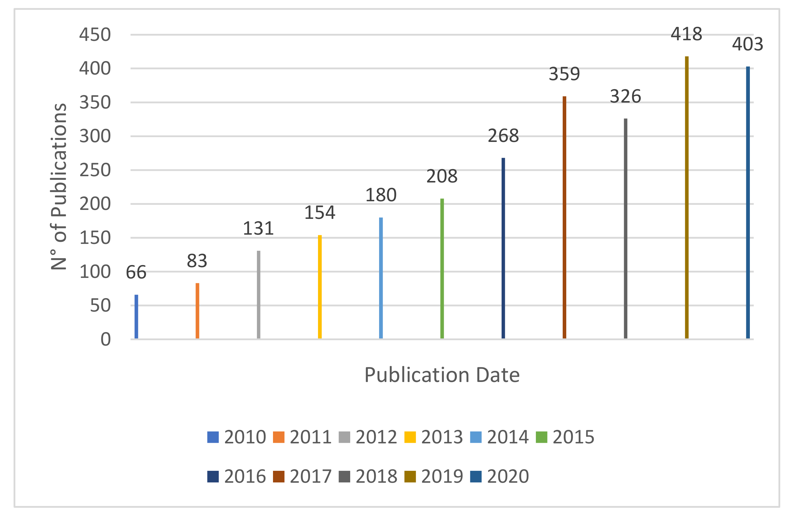
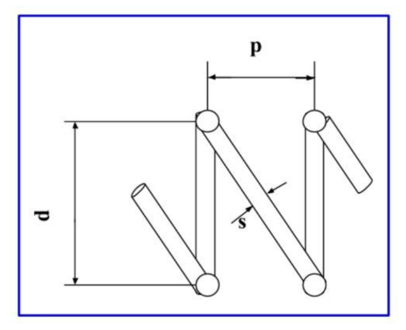
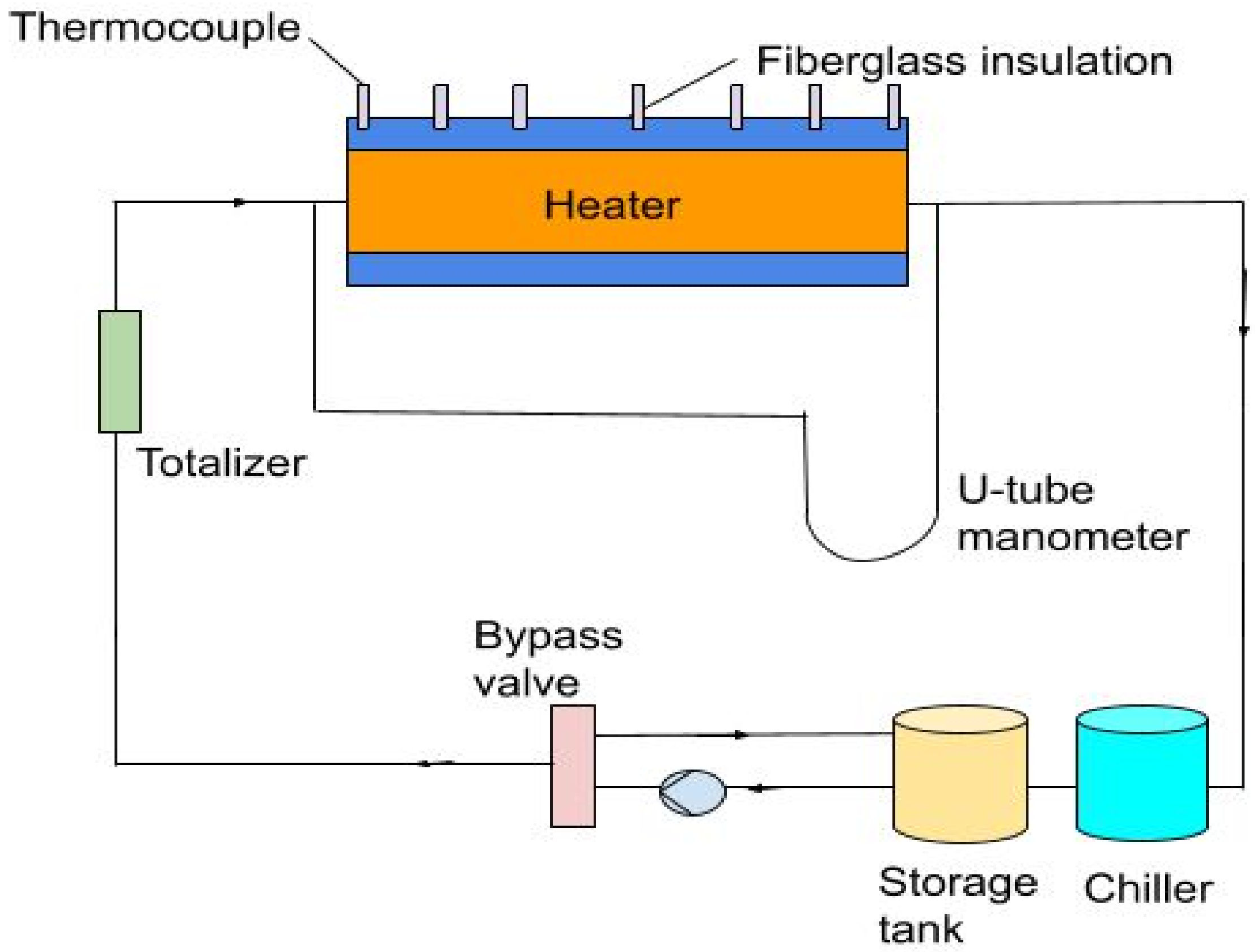
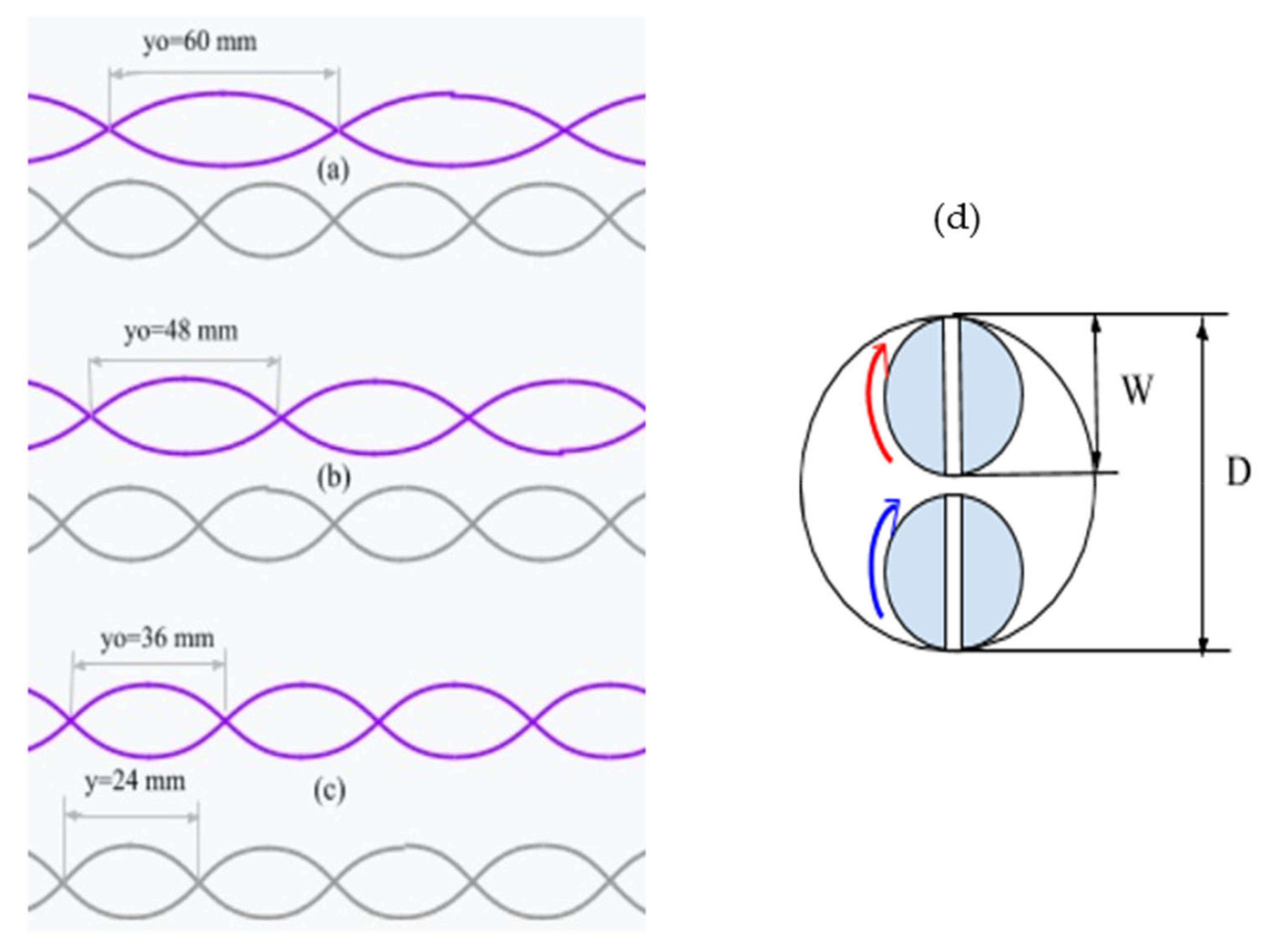
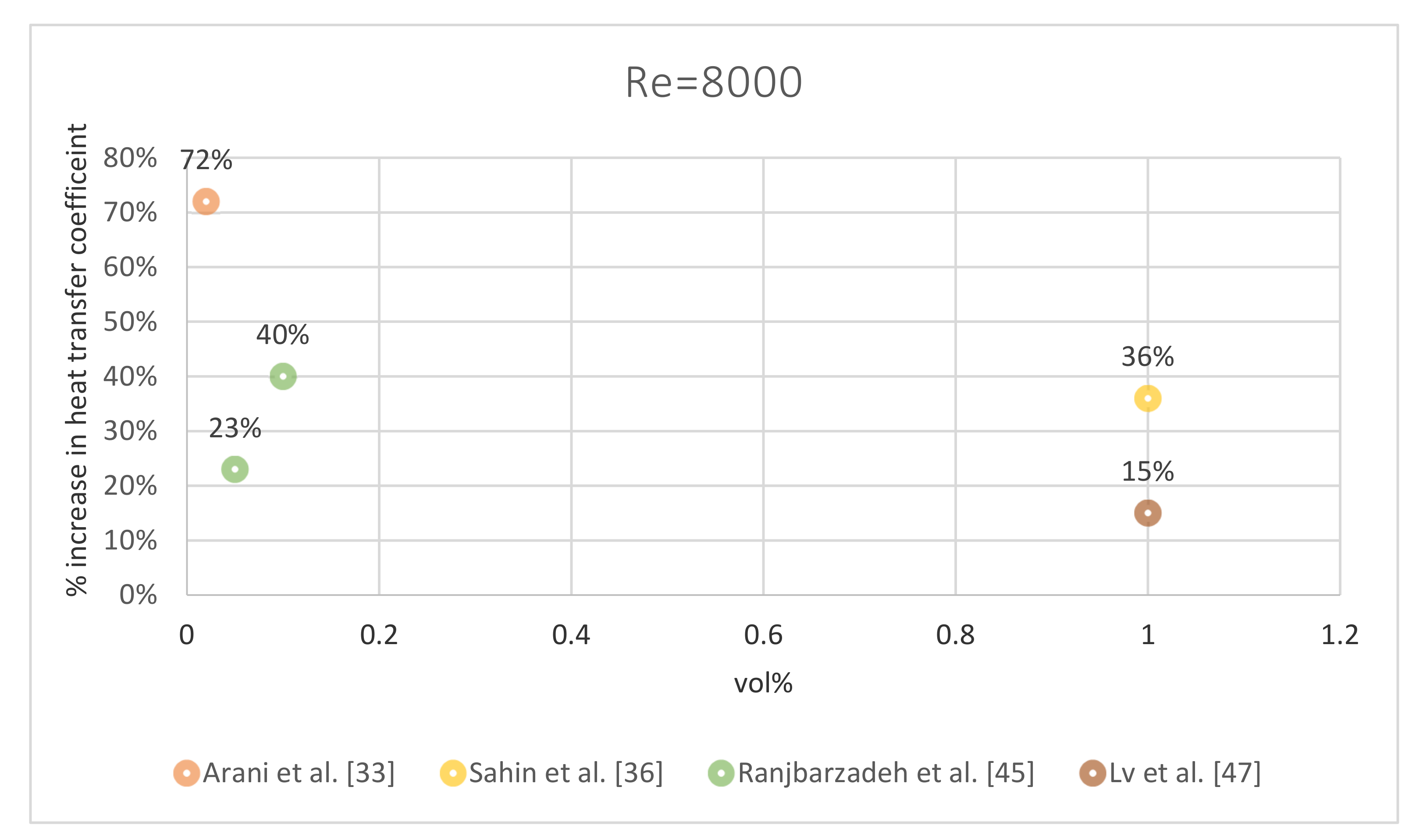
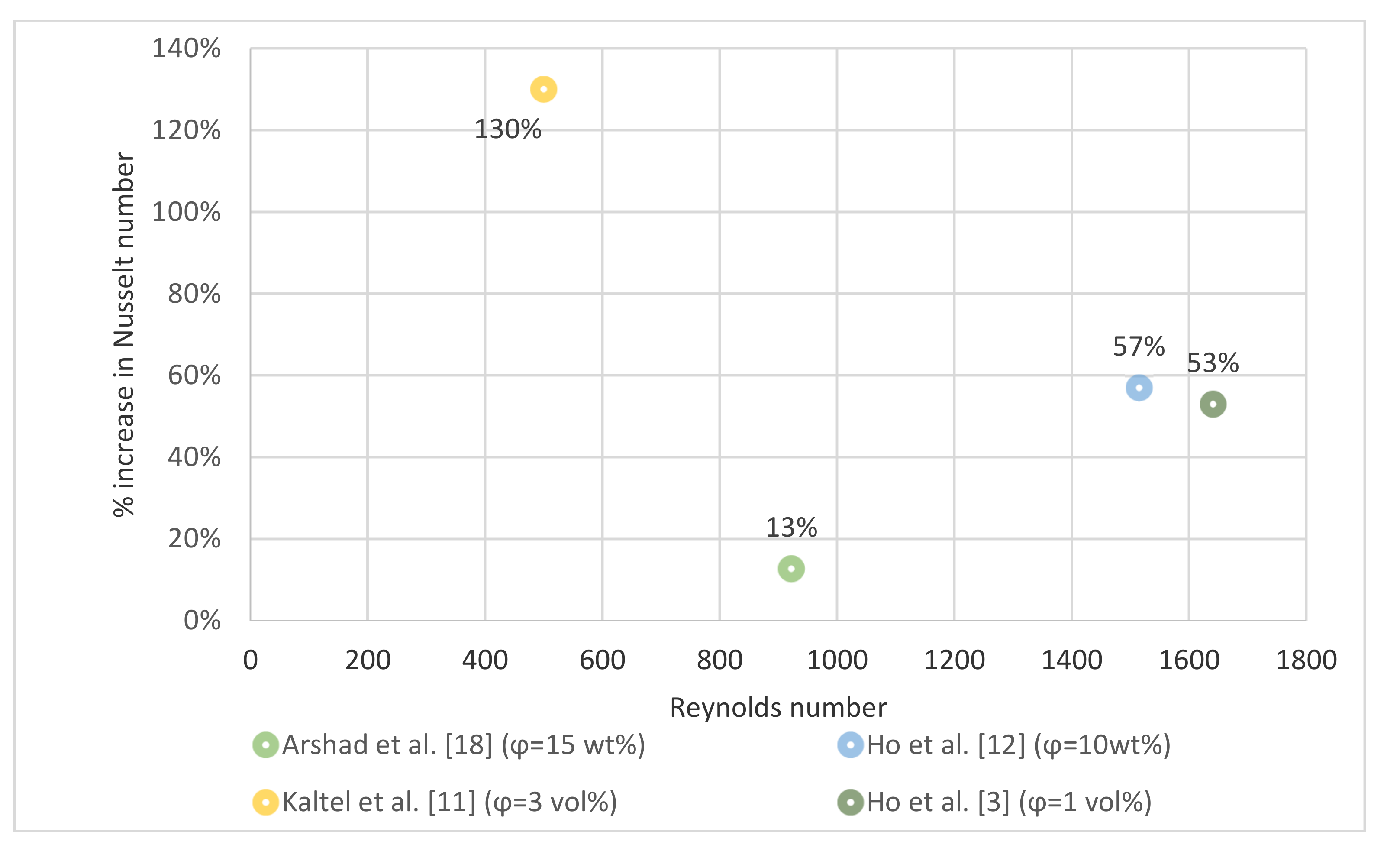


