
Critical Review of Intelligent Battery Systems: Challenges, Implementation, and Potential for Electric Vehicles

 , , , , , , , , , ,
  , , , ,
  ,
,
Abstract
: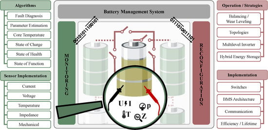
1. Introduction
- additional sensors or advanced monitoring functions on cell level and/or
- actuators such as switches to modify the system’s topology reversibly.
2. Advanced Battery Monitoring
2.1. Fault Diagnosis
- fault detection: recognition of faults;
- fault isolation: localization of faults;
- fault identification: estimation of the type and amplitude of faults;
- fault tolerance: (limited) continuation of operation in the presence of diagnosed faults.
2.2. Online Identification of Model Parameters
2.3. Online Identification of Core Temperature
2.4. Online Identification of State of Charge
2.5. Online Identification of State of Health
2.6. Online Identification of State of Function
3. Implementation of Sensing in Intelligent Battery Systems
3.1. Current
3.2. Voltage
3.3. Impedance
3.4. Temperature
- low costs;
- small size, so that the volumetric energy density of the cell is not significantly reduced
- long term chemical stability towards the electrolyte;
- negligible impact on the cell performance;
- compatible with the cell assembly process;
- reliable operation at least for eight to ten years depending on the local geopolitical regulations.
3.5. Mechanical and Volumetric Change Detection
4. Reconfiguration in Intelligent Battery Systems
- The smallest unit in an RBS can be a single cell or multiple cells combined. Since these cells do not necessarily have to be cells of the same type or even battery cells, the smallest unit is referred to as Energy Storage Unit (ESU) (Figure 6a). However, in the case of multiple cells, the flexibility of having influence on each individual energy storage decreases [374].
- An RBS is characterized by the fact that connections between the inherent ESUs can be changed during operation. As visualized in Figure 6b, an ESU can have three different states:
- -
- An ESU can be switched out of the power path, while the power path is either further maintained after switching of the ESU (bypass state) and/or the switching of the ESUs disrupts the power path (idle state).
- -
- An ESU is switched into the power path (active state).
- An important feature of RBSs is that these states are reversible and can be repeated multiple times during operation. Furthermore, such a system can be designed in a way that it contains multiple load paths and that an ESU is assignable to one or more of them. It is worth noting that an RBS needs to be able to change its configuration in real-time depending on system state [372,373].
- RBS Type 1 uses reconfiguration to directly change the state of an individual ESU. The main goal of this expansion level is to change or adjust the SOC [377,378,379,380], the temperature, and the SOH of an individual ESU as well as to guarantee its operation in case of single ESU failure [379,381]. Reconfiguration is thus used to influence internal states so that the batteries performance matches a new one’s for as long as possible. Since it has the same electrical output characteristics as a conventional battery but an extended lifetime, this technology can directly replace conventional battery systems in BEVs.
- RBS Type 2 performs reconfiguration dynamically and continuously to achieve the desired condition to operate the load, resulting in AC output voltage wave-forms. This leads to a transfer of the power electronics into the battery system and thus a fusion of both components. In the literature, Type 2 is referred to as an Multilevel Inverter (MLI) [382]. Commonly, the system is arranged in multiple strings of ESUs to supply multi-phase AC. In an electric drive train, an IBS with MLI technology can directly operate an electrical machine without additional components.
- RBS Type 3 are battery systems in the form of Type 1 or Type 2. They are used to operate different types of ESUs in one system. This type is called Hybrid Battery Storage System with the goal to combine ESUs e.g., with different energy storage capability or different power ratings [374]. With Type 3, an automobile manufacturer can, for example, replace defective cells in a battery system of an older costumer vehicle, even if the battery technology has changed in the meantime.
4.1. Basic Functions
4.1.1. Bad Block Management
4.1.2. Balancing
4.1.3. Wear Leveling
4.2. Switching Topologies
4.2.1. Microtopology
4.2.2. Macrotopology
4.3. Multilevel Inverter
4.4. Hybrid Battery Storage System
4.4.1. Topologies
4.4.2. Operation
5. Implementation of Reconfigurable Battery Systems
5.1. Switches for Reconfiguration Functionality
5.2. Architecture of the Battery Management System
5.3. Communication in Intelligent Battery Systems
- Reliability, due to the high safety requirements.
- Determinism and real-time capability, especially for safety critical data.
- Bit rate, which depends on the number of cells, the amount of data to be exchanged per cell and the necessary data update rate of the system.
- Scalability, in order to enable cheap and easy adaption for different vehicles and vehicle variants.
- Security, as the network is a common entry door for hackers.
5.4. Further Implications of Reconfiguration
5.4.1. Thermal Influence and Interaction in Reconfigurable Battery Systems
5.4.2. Influence of Switching on Cell Lifetime
5.4.3. Efficient Operation of Reconfigurable Battery Systems
- reduce the internal resistance of a switch by suitable components;
- use multiple switches in parallel for the same functionality;
- reduce the number of single switched ESUs by including multiple cells.
6. Summary, Conclusions, and Outline
Supplementary Materials
Author Contributions
Funding
Acknowledgments
Conflicts of Interest
Abbreviations
| AFE | Analog Front End |
| ANN | Artificial Neural Network |
| ASK | Amplitude Shift Keying |
| BBM | Bad-Block-Management |
| BEV | Battery Electric Vehicle |
| BMS | Battery Management System |
| BPF | Bandpass Filter |
| CAN | Controller Area Network |
| CCCT | Constant Current Charging Time |
| CHB | Cascaded H-Bridge |
| CMU | Cell Management Unit |
| CPSD | Cross Power Spectral Density |
| CVCT | Constant Voltage Charging Time |
| CSR | Current Sense Resistor |
| DFT | Discrete Fourier Transformation |
| DKF | Dual Kalman Filter |
| DOD | Depth of Discharge |
| DVA | Differential Voltage Analysis |
| ECM | Equivalent Circuit Model |
| ECIN | Enhanced Commutation Integrated Nested |
| ESC | External Short Circuit |
| EIS | Electrochemical Impedance Spectroscopy |
| EKF | Extended Kalman Filter |
| EMI | Electromagnetic Interference |
| ESU | Energy Storage Unit |
| ESS | Energy Storage System |
| EV | Electric Vehicle |
| FBG | Fiber Bragg Grating Sensor |
| FC | Flying Capacitor |
| FSK | Frequency Shift Keying |
| GA | Genetic Algorithm |
| GPR | Gaussian Process Regression |
| GTO | Gate Turn Off |
| HBSS | Hybrid Battery Storage System |
| HPF | High Pass Filter |
| HPPC | Hybrid Pulse Power Characterization |
| IBS | Intelligent Battery System |
| ICA | Incremental Capacity Analysis |
| ISC | Internal Short Circuit |
| IGBT | Insulated-Gate Bipolar Transistor |
| IoT | Internet of Things |
| KF | Kalman Filter |
| LAM | Loss of Active Material |
| LCO | Lithium Cobalt Oxide |
| Li-ion | lithium-ion |
| LFP | Lithium Iron Phosphate |
| LLI | Loss of Lithium Inventory |
| LMO | Lithium Manganese Oxide |
| LPF | Lowpass Filter |
| MC | Multi-Carrier |
| MCU | Microcontroller Unit |
| MLI | Multilevel Inverter |
| MOSFET | Metal-Oxide-Semiconductor Field-Effect Transistor |
| MMC | Modular Multilevel Converter |
| MMU | Module Management Unit |
| NCA | Lithium Nickel Cobalt Aluminum Oxide |
| NLC | Nearest Level Control |
| NMC | Lithium Nickel Manganese Cobalt Oxide |
| NPC | Neutral Point Clamped |
| NPS | Neutral Point Shift |
| NTC | Negative Thermal Coefficient |
| OCV | Open Circuit Voltage |
| PECIN | Parallel Enhanced Commutation Integrated Nested |
| PF | Particle Filter |
| PLC | Power Line Communication |
| PSD | Power Spectral Density |
| PSO | Particle Swarm Optimization |
| PWM | Pulse Width Modulation |
| RBS | Reconfigurable Battery System |
| RLS | Recursive Least Squares |
| RTD | Resistance Temperature Detector |
| SEI | Solid Electrolyte Interphase |
| SHE | Selective Harmonic Elimination |
| SOC | State of Charge |
| SOF | State of Function |
| SOH | State of Health |
| SOP | State of Performance |
| SPM | Single Particle Model |
| SPWM | Sinusoidal Pulse Width Modulation |
| SVC | Space Vector Control |
| SVM | Space Vector Modulation |
| SVPWM | Space Vector Pulse Width Modulation |
| SVR | Support Vector Regression |
| TECM | Thermal Equivalent Circuit Model |
| TOF | Time-of-Flight |
| THD | Total Harmonic Distortion |
| UART | Universal Asynchronous Receiver Transmitter |
| UKF | Unscented Kalman Filter |
| WBMS | Wireless Battery Management System |
| WTLS | Weighted Total Least Squares |
References
- Lu, L.; Han, X.; Li, J.; Hua, J.; Ouyang, M. A review on the key issues for lithium-ion battery management in electric vehicles. J. Power Sources 2013, 226, 272–288. [Google Scholar] [CrossRef]
- Liu, X.; Ai, W.; Naylor Marlow, M.; Patel, Y.; Wu, B. The effect of cell-to-cell variations and thermal gradients on the performance and degradation of lithium-ion battery packs. Appl. Energy 2019, 248, 489–499. [Google Scholar] [CrossRef]
- Campestrini, C.; Keil, P.; Schuster, S.F.; Jossen, A. Ageing of lithium-ion battery modules with dissipative balancing compared with single-cell ageing. J. Energy Storage 2016, 6, 142–152. [Google Scholar] [CrossRef]
- Rumpf, K.; Rheinfeld, A.; Schindler, M.; Keil, J.; Schua, T.; Jossen, A. Influence of Cell-to-Cell Variations on the Inhomogeneity of Lithium-Ion Battery Modules. J. Electrochem. Soc. 2018, 165, A2587–A2607. [Google Scholar] [CrossRef]
- Hosseinzadeh, E.; Arias, S.; Krishna, M.; Worwood, D.; Barai, A.; Widanalage, D.; Marco, J. Quantifying cell-to-cell variations of a parallel battery module for different pack configurations. Appl. Energy 2021, 282, 115859. [Google Scholar] [CrossRef]
- Paul, S.; Diegelmann, C.; Kabza, H.; Tillmetz, W. Analysis of ageing inhomogeneities in lithium-ion battery systems. J. Power Sources 2013, 239, 642–650. [Google Scholar] [CrossRef]
- Saidani, F.; Hutter, F.X.; Selinger, W.; Yu, Z.; Burghartz, J.N. A lithium-ion battery demonstrator for HEV applications featuring a smart system at cell level. In Proceedings of the 2017 IEEE International Systems Engineering Symposium (ISSE), Vienna, Austria, 11–13 October 2017; pp. 1–5. [Google Scholar] [CrossRef]
- Schneider, D.; Liebhart, B.; Endisch, C. Active state and parameter estimation as part of intelligent battery systems. J. Energy Storage 2021, 39, 102638. [Google Scholar] [CrossRef]
- Lorentz, V.; Wenger, M.; Giegerich, M.; Zeltner, S.; März, M.; Frey, L. Smart Battery Cell Monitoring with Contactless Data Transmission. In Advanced Microsystems for Automotive Applications 2012; Meyer, G., Ed.; Springer: Berlin/Heidelberg, Germany, 2012. [Google Scholar]
- Kim, T.; Qiao, W.; Qu, L. Series-connected reconfigurable multicell battery: A novel design towards smart batteries. In Proceedings of the 2010 IEEE Energy Conversion Congress and Exposition, Atlanta, GA, USA, 12–16 September 2010; pp. 4257–4263. [Google Scholar] [CrossRef]
- Canfield, D. Smart Battery with Integrated Sensing and Electronics. U.S. Patent 20170092994 A1, 30 March 2017. [Google Scholar]
- Butzmann, S. Battery Having a Plurality of Battery Cells and Method for Regulating a Battery Voltage of a Battery Using Switchon Probabilities of the Battery Cells. U.S. Patent 9362760 B2, 7 June 2016. [Google Scholar]
- Hinterberger, M.; Hellenthal, B. Smart Battery Cell of a Battery for a Motor Vehicle. U.S. Patent 10361466B2, 23 July 2019. [Google Scholar]
- Hinterberger, M.; Hellenthal, B. Battery Cell for a Battery of a Motor Vehicle, Battery, and Motor Vehicle. CN 107210418 B, 26 September 2017. [Google Scholar]
- Wei, Z.; Zhao, J.; He, H.; Ding, G.; Cui, H.; Liu, L. Future smart battery and management: Advanced sensing from external to embedded multi-dimensional measurement. J. Power Sources 2021, 489, 229462. [Google Scholar] [CrossRef]
- Xia, G.; Cao, L.; Bi, G. A review on battery thermal management in electric vehicle application. J. Power Sources 2017, 367, 90–105. [Google Scholar] [CrossRef]
- Wu, C.; Zhu, C.; Ge, Y.; Zhao, Y. A Review on Fault Mechanism and Diagnosis Approach for Li-Ion Batteries. J. Nanomater. 2015, 2015, 631263. [Google Scholar] [CrossRef] [Green Version]
- Shen, M.; Gao, Q. A review on battery management system from the modeling efforts to its multiapplication and integration. Int. J. Energy Res. 2019, 43, 5042–5075. [Google Scholar] [CrossRef]
- Kim, I.S. A Technique for Estimating the State of Health of Lithium Batteries Through a Dual-Sliding-Mode Observer. IEEE Trans. Power Electron. 2010, 25, 1013–1022. [Google Scholar] [CrossRef]
- Dixon, J.; Pereda, J.; Castillo, C.; Bosch, S. Asymmetrical Multilevel Inverter for Traction Drives Using Only One DC Supply. IEEE Trans. Veh. Technol. 2010, 59, 3736–3743. [Google Scholar] [CrossRef]
- Waag, W.; Fleischer, C.; Sauer, D.U. Critical review of the methods for monitoring of lithium-ion batteries in electric and hybrid vehicles. J. Power Sources 2014, 258, 321–339. [Google Scholar] [CrossRef]
- Lipu, M.H.; Hannan, M.A.; Hussain, A.; Hoque, M.M.; Ker, P.J.; Saad, M.; Ayob, A. A review of state of health and remaining useful life estimation methods for lithium-ion battery in electric vehicles: Challenges and recommendations. J. Clean. Prod. 2018, 205, 115–133. [Google Scholar] [CrossRef]
- Ripka, P. Electric current sensors: A review. Meas. Sci. Technol. 2010, 21, 112001. [Google Scholar] [CrossRef] [Green Version]
- Lyu, D.; Ren, B.; Li, S. Failure modes and mechanisms for rechargeable Lithium-based batteries: A state-of-the-art review. Acta Mech. 2019, 230, 701–727. [Google Scholar] [CrossRef]
- Tran, M.K.; Fowler, M. Sensor Fault Detection and Isolation for Degrading Lithium-Ion Batteries in Electric Vehicles Using Parameter Estimation with Recursive Least Squares. Batteries 2020, 6, 1. [Google Scholar] [CrossRef] [Green Version]
- Hu, X.; Jiang, Z.; Yan, L.; Yang, G.; Xie, J.; Liu, S.; Zhang, Q.; Xiang, Y.; Min, H.; Peng, X. Real-time visualized battery health monitoring sensor with piezoelectric/pyroelectric poly (vinylidene fluoride-trifluoroethylene) and thin film transistor array by in-situ poling. J. Power Sources 2020, 467, 228367. [Google Scholar] [CrossRef]
- Wang, H.; Simunovic, S.; Maleki, H.; Howard, J.N.; Hallmark, J.A. Internal configuration of prismatic lithium-ion cells at the onset of mechanically induced short circuit. J. Power Sources 2016, 306, 424–430. [Google Scholar] [CrossRef] [Green Version]
- Diao, W.; Xing, Y.; Saxena, S.; Pecht, M. Evaluation of Present Accelerated Temperature Testing and Modeling of Batteries. Appl. Sci. 2018, 8, 1786. [Google Scholar] [CrossRef] [Green Version]
- Xiong, R.; Yu, Q.; Shen, W. Review on sensors fault diagnosis and fault-tolerant techniques for lithium ion batteries in electric vehicles. In Proceedings of the 2018 13th IEEE Conference on Industrial Electronics and Applications (ICIEA), Wuhan, China, 31 May–2 June 2018; pp. 406–410. [Google Scholar] [CrossRef]
- Yao, L.; Wang, Z.; Ma, J. Fault detection of the connection of lithium-ion power batteries based on entropy for electric vehicles. J. Power Sources 2015, 293, 548–561. [Google Scholar] [CrossRef]
- Offer, G.J.; Yufit, V.; Howey, D.A.; Wu, B.; Brandon, N.P. Module design and fault diagnosis in electric vehicle batteries. J. Power Sources 2012, 206, 383–392. [Google Scholar] [CrossRef] [Green Version]
- Schmid, M.; Gebauer, E.; Hanzl, C.; Endisch, C. Active Model-Based Fault Diagnosis in Reconfigurable Battery Systems. IEEE Trans. Power Electron. 2021, 36, 2584–2597. [Google Scholar] [CrossRef]
- Lombardi, W.; Zarudniev, M.; Lesecq, S.; Bacquet, S. Sensors fault diagnosis for a BMS. In Proceedings of the 2014 European Control Conference (ECC 2014), Strasbourg, France, 24–27 June 2014; IEEE: Piscataway, NJ, USA, 2014; pp. 952–957. [Google Scholar] [CrossRef]
- Schmid, M.; Gebauer, E.; Endisch, C. Structural Analysis in Reconfigurable Battery Systems for Active Fault Diagnosis. IEEE Trans. Power Electron. 2021, 36, 8672–8684. [Google Scholar] [CrossRef]
- Xia, B.; Mi, C. A fault-tolerant voltage measurement method for series connected battery packs. J. Power Sources 2016, 308, 83–96. [Google Scholar] [CrossRef]
- Xia, B.; Nguyen, T.; Yang, J.; Mi, C. The improved interleaved voltage measurement method for series connected battery packs. J. Power Sources 2016, 334, 12–22. [Google Scholar] [CrossRef] [Green Version]
- Kang, Y.; Duan, B.; Zhou, Z.; Shang, Y.; Zhang, C. A multi-fault diagnostic method based on an interleaved voltage measurement topology for series connected battery packs. J. Power Sources 2019, 417, 132–144. [Google Scholar] [CrossRef]
- Schmid, M.; Kneidinger, H.G.; Endisch, C. Data-Driven Fault Diagnosis in Battery Systems through Cross-Cell Monitoring. IEEE Sens. J. 2020, 21, 1829–1837. [Google Scholar] [CrossRef]
- Schmid, M.; Liebhart, B.; Kleiner, J.; Endisch, C.; Kennel, R. Online Detection of Soft Internal Short Circuits in Lithium-Ion Battery Packs by Data-Driven Cell Voltage Monitoring. In Proceedings of the 2021 IEEE International Conference on Electrical and Electromechanical Energy Conversion (ECCE Asia), Singapore, 24–27 May 2021; pp. 1711–1718. [Google Scholar] [CrossRef]
- Dubarry, M.; Truchot, C.; Liaw, B.Y. Cell degradation in commercial LiFePO4 cells with high-power and high-energy designs. J. Power Sources 2014, 258, 408–419. [Google Scholar] [CrossRef]
- Dubarry, M.; Liaw, B.Y. Identify capacity fading mechanism in a commercial LiFePO4 cell. J. Power Sources 2009, 194, 541–549. [Google Scholar] [CrossRef]
- Bloom, I.; Christophersen, J.; Gering, K. Differential voltage analyses of high-power lithium-ion cells. J. Power Sources 2005, 139, 304–313. [Google Scholar] [CrossRef]
- Singh, A.; Izadian, A.; Anwar, S. Fault diagnosis of Li-Ion batteries using multiple-model adaptive estimation. In Proceedings of the 39th annual conference of the IEEE Industrial Electronics Societ, Vienna, Austria, 10–13 November 2013; pp. 3524–3529. [Google Scholar] [CrossRef]
- Sidhu, A.; Izadian, A.; Anwar, S. Adaptive Nonlinear Model-Based Fault Diagnosis of Li-Ion Batteries. IEEE Trans. Ind. Electron. 2015, 62, 1002–1011. [Google Scholar] [CrossRef] [Green Version]
- Alavi, S.M.M.; Samadi, M.F.; Saif, M. Plating Mechanism Detection in Lithium-ion batteries, by using a particle-filtering based estimation technique. In Proceedings of the 2013 American Control Conference (ACC 2013), Washington, DC, USA, 17–19 June 2013; IEEE: Piscataway, NJ, USA, 2013; pp. 4356–4361. [Google Scholar] [CrossRef]
- Tian, J.; Wang, Y.; Chen, Z. Sensor fault diagnosis for lithium-ion battery packs based on thermal and electrical models. Int. J. Electr. Power Energy Syst. 2020, 121, 106087. [Google Scholar] [CrossRef]
- Zheng, C.; Chen, Z.; Huang, D. Fault diagnosis of voltage sensor and current sensor for lithium-ion battery pack using hybrid system modeling and unscented particle filter. Energy 2020, 191, 116504. [Google Scholar] [CrossRef]
- Lin, T.; Chen, Z.; Zheng, C.; Huang, D.; Zhou, S. Fault diagnosis of lithium-ion battery pack based on hybrid system and dual extended Kalman filter algorithm. IEEE Trans. Transp. Electrif. 2020, 7, 26–36. [Google Scholar] [CrossRef]
- Xiong, R.; Yu, Q.; Shen, W.; Lin, C.; Sun, F. A Sensor Fault Diagnosis Method for a Lithium-Ion Battery Pack in Electric Vehicles. IEEE Trans. Power Electron. 2019, 34, 9709–9718. [Google Scholar] [CrossRef]
- Liu, Z.; He, H. Sensor fault detection and isolation for a lithium-ion battery pack in electric vehicles using adaptive extended Kalman filter. Appl. Energy 2017, 185, 2033–2044. [Google Scholar] [CrossRef]
- Liu, Z.; Ahmed, Q.; Zhang, J.; Rizzoni, G.; He, H. Structural analysis based sensors fault detection and isolation of cylindrical lithium-ion batteries in automotive applications. Control Eng. Pract. 2016, 52, 46–58. [Google Scholar] [CrossRef] [Green Version]
- Liu, Z.; He, H. Model-based Sensor Fault Diagnosis of a Lithium-ion Battery in Electric Vehicles. Energies 2015, 8, 6509–6527. [Google Scholar] [CrossRef]
- He, H.; Liu, Z.; Hua, Y. Adaptive Extended Kalman Filter Based Fault Detection and Isolation for a Lithium-Ion Battery Pack. Energy Procedia 2015, 75, 1950–1955. [Google Scholar] [CrossRef] [Green Version]
- Gadsden, S.A.; Habibi, S.R. Model-based fault detection of a battery system in a hybrid electric vehicle. In Proceedings of the IEEE Vehicle Power and Propulsion Conference 2011, Chicago, IL, USA, 6–9 September 2011; pp. 1–6. [Google Scholar] [CrossRef]
- Dey, S.; Biron, Z.A.; Tatipamula, S.; Das, N.; Mohon, S.; Ayalew, B.; Pisu, P. On-board Thermal Fault Diagnosis of Lithium-ion Batteries For Hybrid Electric Vehicle Application. IFAC-PapersOnLine 2015, 48, 389–394. [Google Scholar] [CrossRef]
- Dey, S.; Biron, Z.A.; Tatipamula, S.; Das, N.; Mohon, S.; Ayalew, B.; Pisu, P. Model-based real-time thermal fault diagnosis of Lithium-ion batteries. Control Eng. Pract. 2016, 56, 37–48. [Google Scholar] [CrossRef] [Green Version]
- Dey, S.; Perez, H.E.; Moura, S.J. Model-Based Battery Thermal Fault Diagnostics: Algorithms, Analysis, and Experiments. IEEE Trans. Control Syst. Technol. 2019, 27, 576–587. [Google Scholar] [CrossRef]
- Xu, J.; Wang, J.; Li, S.; Cao, B. A Method to Simultaneously Detect the Current Sensor Fault and Estimate the State of Energy for Batteries in Electric Vehicles. Sensors 2016, 16, 1328. [Google Scholar] [CrossRef] [Green Version]
- Dey, S.; Mohon, S.; Pisu, P.; Ayalew, B. Sensor Fault Detection, Isolation, and Estimation in Lithium-Ion Batteries. IEEE Trans. Control Syst. Technol. 2016, 24, 2141–2149. [Google Scholar] [CrossRef]
- Zhang, H.; Pei, L.; Sun, J.; Song, K.; Lu, R.; Zhao, Y.; Zhu, C.; Wang, T. Online Diagnosis for the Capacity Fade Fault of a Parallel-Connected Lithium Ion Battery Group. Energies 2016, 9, 387. [Google Scholar] [CrossRef] [Green Version]
- Marcicki, J.; Onori, S.; Rizzoni, G. Nonlinear Fault Detection and Isolation for a Lithium-Ion Battery Management System. In Proceedings of the ASME 2010 Dynamic Systems and Control Conference, Cambridge, MA, USA, 12–15 September 2010; ASME: New York, NY, USA, 2010; pp. 607–614. [Google Scholar] [CrossRef] [Green Version]
- Liu, Z.; He, H.; Ahmed, Q.; Rizzoni, G. Structural Analysis Based Fault Detection and Isolation Applied for A Lithium-Ion Battery Pack. IFAC-PapersOnLine 2015, 48, 1465–1470. [Google Scholar] [CrossRef]
- Liu, Z.; Ahmed, Q.; Rizzoni, G.; He, H. Fault Detection and Isolation for Lithium-Ion Battery System Using Structural Analysis and Sequential Residual Generation. In Proceedings of the ASME 2014 Dynamic Systems and Control Conference, DSCC 2014, San Antonio, TX, USA, 22–24 October 2014; Volume 2. [Google Scholar] [CrossRef]
- Shang, Y.; Lu, G.; Kang, Y.; Zhou, Z.; Duan, B.; Zhang, C. A multi-fault diagnosis method based on modified Sample Entropy for lithium-ion battery strings. J. Power Sources 2020, 446, 227275. [Google Scholar] [CrossRef]
- Ma, M.; Wang, Y.; Duan, Q.; Wu, T.; Sun, J.; Wang, Q. Fault detection of the connection of lithium-ion power batteries in series for electric vehicles based on statistical analysis. Energy 2018, 164, 745–756. [Google Scholar] [CrossRef]
- Sun, Z.; Liu, P.; Wang, Z. Real-time Fault Diagnosis Method of Battery System Based on Shannon Entropy. Energy Procedia 2017, 105, 2354–2359. [Google Scholar] [CrossRef]
- Zheng, Y.; Han, X.; Lu, L.; Li, J.; Ouyang, M. Lithium ion battery pack power fade fault identification based on Shannon entropy in electric vehicles. J. Power Sources 2013, 223, 136–146. [Google Scholar] [CrossRef]
- Yao, L.; Fang, Z.; Xiao, Y.; Hou, J.; Fu, Z. An Intelligent Fault Diagnosis Method for Lithium Battery Systems Based on Grid Search Support Vector Machine. Energy 2021, 214, 118866. [Google Scholar] [CrossRef]
- Lai, X.; Yi, W.; Kong, X.; Han, X.; Zhou, L.; Sun, T.; Zheng, Y. Online detection of early stage internal short circuits in series-connected lithium-ion battery packs based on state-of-charge correlation. J. Energy Storage 2020, 30, 101514. [Google Scholar] [CrossRef]
- Gao, W.; Zheng, Y.; Ouyang, M.; Li, J.; Lai, X.; Hu, X. Micro-Short-Circuit Diagnosis for Series-Connected Lithium-Ion Battery Packs Using Mean-Difference Model. IEEE Trans. Ind. Electron. 2019, 66, 2132–2142. [Google Scholar] [CrossRef]
- Feng, X.; Pan, Y.; He, X.; Wang, L.; Ouyang, M. Detecting the internal short circuit in large-format lithium-ion battery using model-based fault-diagnosis algorithm. J. Energy Storage 2018, 18, 26–39. [Google Scholar] [CrossRef]
- Chen, W.; Chen, W.T.; Saif, M.; Li, M.F.; Wu, H. Simultaneous Fault Isolation and Estimation of Lithium-Ion Batteries via Synthesized Design of Luenberger and Learning Observers. IEEE Trans. Control Syst. Technol. 2014, 22, 290–298. [Google Scholar] [CrossRef]
- Xu, J.; Wang, H.; Shi, H.; Mei, X. Multi-scale short circuit resistance estimation method for series connected battery strings. Energy 2020, 202, 117647. [Google Scholar] [CrossRef]
- Meng, J.; Boukhnifer, M.; Delpha, C.; Diallo, D. Incipient short-circuit fault diagnosis of lithium-ion batteries. J. Energy Storage 2020, 31, 101658. [Google Scholar] [CrossRef]
- Seo, M.; Park, M.; Song, Y.; Kim, S.W. Online Detection of Soft Internal Short Circuit in Lithium-Ion Batteries at Various Standard Charging Ranges. IEEE Access 2020, 8, 70947–70959. [Google Scholar] [CrossRef]
- Seo, M.; Goh, T.; Park, M.; Koo, G.; Kim, S. Detection of Internal Short Circuit in Lithium Ion Battery Using Model-Based Switching Model Method. Energies 2017, 10, 76. [Google Scholar] [CrossRef]
- Feng, X.; Weng, C.; Ouyang, M.; Sun, J. Online internal short circuit detection for a large format lithium ion battery. Appl. Energy 2016, 161, 168–180. [Google Scholar] [CrossRef] [Green Version]
- Ouyang, M.; Zhang, M.; Feng, X.; Lu, L.; Li, J.; He, X.; Zheng, Y. Internal short circuit detection for battery pack using equivalent parameter and consistency method. J. Power Sources 2015, 294, 272–283. [Google Scholar] [CrossRef]
- Kong, X.; Zheng, Y.; Ouyang, M.; Lu, L.; Li, J.; Zhang, Z. Fault diagnosis and quantitative analysis of micro-short circuits for lithium-ion batteries in battery packs. J. Power Sources 2018, 395, 358–368. [Google Scholar] [CrossRef]
- Kim, J.; Cho, B.H. An innovative approach for characteristic analysis and state-of-health diagnosis for a Li-ion cell based on the discrete wavelet transform. J. Power Sources 2014, 260, 115–130. [Google Scholar] [CrossRef]
- Xia, B.; Shang, Y.; Nguyen, T.; Mi, C. A correlation based fault detection method for short circuits in battery packs. J. Power Sources 2017, 337, 1–10. [Google Scholar] [CrossRef] [Green Version]
- Li, X.; Wang, Z. A novel fault diagnosis method for lithium-Ion battery packs of electric vehicles. Measurement 2018, 116, 402–411. [Google Scholar] [CrossRef]
- Liu, P.; Sun, Z.; Wang, Z.; Zhang, J. Entropy-Based Voltage Fault Diagnosis of Battery Systems for Electric Vehicles. Energies 2018, 11, 136. [Google Scholar] [CrossRef] [Green Version]
- Wang, Z.; Hong, J.; Liu, P.; Zhang, L. Voltage fault diagnosis and prognosis of battery systems based on entropy and Z -score for electric vehicles. Appl. Energy 2017, 196, 289–302. [Google Scholar] [CrossRef]
- Zheng, Y.; Lu, Y.; Gao, W.; Han, X.; Feng, X.; Ouyang, M. Micro-Short-Circuit Cell Fault Identification Method for Lithium-ion Battery Packs Based on the Mutual Information. IEEE Trans. Ind. Electron. 2020, 68, 4373–4381. [Google Scholar] [CrossRef]
- Hong, J.; Wang, Z.; Liu, P. Big-Data-Based Thermal Runaway Prognosis of Battery Systems for Electric Vehicles. Energies 2017, 10, 919. [Google Scholar] [CrossRef] [Green Version]
- Xue, Q.; Li, G.; Zhang, Y.; Shen, S.; Chen, Z.; Liu, Y. Fault diagnosis and abnormality detection of lithium-ion battery packs based on statistical distribution. J. Power Sources 2021, 482, 228964. [Google Scholar] [CrossRef]
- Diao, W.; Naqvi, I.H.; Pecht, M. Early detection of anomalous degradation behavior in lithium-ion batteries. J. Energy Storage 2020, 32, 101710. [Google Scholar] [CrossRef]
- Haider, S.N.; Zhao, Q.; Li, X. Data driven battery anomaly detection based on shape based clustering for the data centers class. J. Energy Storage 2020, 29, 101479. [Google Scholar] [CrossRef]
- Da, L.; Zhang, Z.; Liu, P.; Wang, Z.; Zhang, L. Battery Fault Diagnosis for Electric Vehicles Based on Voltage Abnormality by Combining the Long Short-Term Memory Neural Network and the Equivalent Circuit Model. IEEE Trans. Power Electron. 2021, 36, 1303–1315. [Google Scholar] [CrossRef]
- Ojo, O.; Lang, H.; Kim, Y.; Hu, X.; Mu, B.; Lin, X. A Neural Network-Based Method for Thermal Fault Detection in Lithium-Ion Batteries. IEEE Trans. Ind. Electron. 2020, 68, 4068–4078. [Google Scholar] [CrossRef]
- Xiong, J.; Banvait, H.; Li, L.; Chen, Y.; Xie, J.; Liu, Y.; Wu, M.; Chen, J. Failure detection for over-discharged Li-ion batteries. In Proceedings of the 2012 IEEE International Electric Vehicle Conference, Greenville, SC, USA, 4–8 March 2012; pp. 1–5. [Google Scholar] [CrossRef]
- Gao, W.; Li, X.; Ma, M.; Fu, Y.; Jiang, J.; Mi, C. Case Study of an Electric Vehicle Battery Thermal Runaway and Online Internal Short Circuit Detection. IEEE Trans. Power Electron. 2020, 36, 2452–2455. [Google Scholar] [CrossRef]
- Xia, B.; Chen, Z.; Mi, C.; Robert, B. External short circuit fault diagnosis for lithium-ion batteries. In Proceedings of the IEEE Transportation Electrification Conference and Expo (ITEC), Dearborn, MI, USA, 15–18 June 2014; IEEE: Piscataway, NJ, USA, 2014; pp. 1–7. [Google Scholar] [CrossRef]
- Muddappa, V.K.S.; Anwar, S. Electrochemical Model Based Fault Diagnosis of Li-Ion Battery Using Fuzzy Logic. In Proceedings of the ASME International Mechanical Engineering Congress and Exposition, Montreal, QC, Canada, 14–20 November 2014; ASME: New York, NY, USA, 2015. [Google Scholar] [CrossRef]
- Kaypmaz, T.C.; Tuncay, R.N. An advanced cell model for diagnosing faults in operation of Li-ion Polymer batteries. In Proceedings of the IEEE Vehicle Power and Propulsion Conference (VPPC), Chicago, IL, USA, 6–9 September 2011; IEEE: Piscataway, NJ, USA, 2011; pp. 1–5. [Google Scholar] [CrossRef]
- Yang, R.; Xiong, R.; He, H.; Chen, Z. A fractional-order model-based battery external short circuit fault diagnosis approach for all-climate electric vehicles application. J. Clean. Prod. 2018, 187, 950–959. [Google Scholar] [CrossRef]
- Zhao, Y.; Liu, P.; Wang, Z.; Zhang, L.; Hong, J. Fault and defect diagnosis of battery for electric vehicles based on big data analysis methods. Appl. Energy 2017, 207, 354–362. [Google Scholar] [CrossRef]
- Schmid, M.; Vögele, U.; Endisch, C. A novel matrix-vector-based framework for modeling and simulation of electric vehicle battery packs. J. Energy Storage 2020, 32, 101736. [Google Scholar] [CrossRef]
- Xiong, R.; Sun, F.; Chen, Z.; He, H. A data-driven multi-scale extended Kalman filtering based parameter and state estimation approach of lithium-ion polymer battery in electric vehicles. Appl. Energy 2014, 113, 463–476. [Google Scholar] [CrossRef]
- Wang, Q.; Kang, J.; Tan, Z.; Luo, M. An online method to simultaneously identify the parameters and estimate states for lithium ion batteries. Electrochim. Acta 2018, 289, 376–388. [Google Scholar] [CrossRef]
- Wei, Z.; Zhao, J.; Zou, C.; Lim, T.M.; Tseng, K.J. Comparative study of methods for integrated model identification and state of charge estimation of lithium-ion battery. J. Power Sources 2018, 402, 189–197. [Google Scholar] [CrossRef]
- Wang, Y.; Zhao, L.; Cheng, J.; Zhou, J.; Wang, S. A State of Charge Estimation Method of Lithium-Ion Battery Based on Fused Open Circuit Voltage Curve. Appl. Sci. 2020, 10, 1264. [Google Scholar] [CrossRef] [Green Version]
- Meng, J.; Boukhnifer, M.; Diallo, D.; Wang, T. A New Cascaded Framework for Lithium-Ion Battery State and Parameter Estimation. Appl. Sci. 2020, 10, 1009. [Google Scholar] [CrossRef] [Green Version]
- Dai, H.; Wei, X.; Sun, Z. Recursive Parameter Identification of Lithium-Ion Battery for EVs Based on Equivalent Circuit Model. J. Comput. Theor. Nanosci. 2013, 10, 2813–2818. [Google Scholar] [CrossRef]
- Xia, J.; Dai, H.; Sun, Z.; Venturi, M. Parameter Identification of Battery Pack Considering Cell Inconsistency. In Proceedings of the SAE World Congress Experience 2017, Detroit, MI, USA, 4–6 April 2017. [Google Scholar] [CrossRef]
- Wen, F.; Duan, B.; Zhang, C.; Zhu, R.; Shang, Y.; Zhang, J. High-Accuracy Parameter Identification Method for Equivalent-Circuit Models of Lithium-Ion Batteries Based on the Stochastic Theory Response Reconstruction. Electronics 2019, 8, 834. [Google Scholar] [CrossRef] [Green Version]
- Wei, Z.; Zou, C.; Leng, F.; Soong, B.H.; Tseng, K.J. Online Model Identification and State-of-Charge Estimate for Lithium-Ion Battery With a Recursive Total Least Squares-Based Observer. IEEE Trans. Ind. Electron. 2018, 65, 1336–1346. [Google Scholar] [CrossRef]
- Chiang, Y.H.; Sean, W.Y.; Ke, J.C. Online estimation of internal resistance and open-circuit voltage of lithium-ion batteries in electric vehicles. J. Power Sources 2011, 196, 3921–3932. [Google Scholar] [CrossRef]
- Ali, M.U.; Zafar, A.; Nengroo, S.H.; Hussain, S.; Kim, H.J. Effect of Sensors Sensitivity on Lithium-Ion Battery Modeled Parameters and State of Charge: A Comparative Study: State of charge (SOC); sensitivity analysis; current sensor precision; voltage sensor precision. Electronics 2019, 8, 709. [Google Scholar] [CrossRef] [Green Version]
- Pang, H.; Zhang, F. Experimental Data-Driven Parameter Identification and State of Charge Estimation for a Li-Ion Battery Equivalent Circuit Model. Energies 2018, 11, 1033. [Google Scholar] [CrossRef] [Green Version]
- Liebhart, B.; Komsiyska, L.; Endisch, C. Passive impedance spectroscopy for monitoring lithium-ion battery cells during vehicle operation. J. Power Sources 2020, 449, 227297. [Google Scholar] [CrossRef]
- Troxler, Y.; Wu, B.; Marinescu, M.; Yufit, V.; Patel, Y.; Marquis, A.J.; Brandon, N.P.; Offer, G.J. The effect of thermal gradients on the performance of lithium-ion batteries. J. Power Sources 2014, 247, 1018–1025. [Google Scholar] [CrossRef]
- Arora, S.; Shen, W.; Kapoor, A. Neural network based computational model for estimation of heat generation in LiFePO4 pouch cells of different nominal capacities. Comput. Chem. Eng. 2017, 101, 81–94. [Google Scholar] [CrossRef]
- Cui, X.; Zeng, J.; Zhang, H.; Yang, J.; Qiao, J.; Li, J.; Li, W. Optimization of the lumped parameter thermal model for hard-cased li-ion batteries. J. Energy Storage 2020, 32, 101758. [Google Scholar] [CrossRef]
- Lundgren, H.; Svens, P.; Ekström, H.; Tengstedt, C.; Lindström, J.; Behm, M.; Lindbergh, G. Thermal Management of Large-Format Prismatic Lithium-Ion Battery in PHEV Application. J. Electrochem. Soc. 2016, 163, A309–A317. [Google Scholar] [CrossRef]
- Kleiner, J.; Komsiyska, L.; Elger, G.; Endisch, C. Thermal Modelling of a Prismatic Lithium-Ion Cell in a Battery Electric Vehicle Environment: Influences of the Experimental Validation Setup. Energies 2020, 13, 62. [Google Scholar] [CrossRef] [Green Version]
- Baumann, M.; Rohr, S.; Lienkamp, M. Cloud-connected battery management for decision-making on second-life of electric vehicle batteries. In Proceedings of the 2018 Thirteenth International Conference, Monte Carlo, Monaco, 10–12 April 2018; pp. 1–6. [Google Scholar] [CrossRef]
- Jiang, J.; Ruan, H.; Sun, B.; Zhang, W.; Gao, W.; Le Wang, Y.; Zhang, L. A reduced low-temperature electro-thermal coupled model for lithium-ion batteries. Appl. Energy 2016, 177, 804–816. [Google Scholar] [CrossRef] [Green Version]
- Richardson, R.R.; Ireland, P.T.; Howey, D.A. Battery internal temperature estimation by combined impedance and surface temperature measurement. J. Power Sources 2014, 265, 254–261. [Google Scholar] [CrossRef]
- Richardson, R.R.; Zhao, S.; Howey, D.A. On-board monitoring of 2D spatially-resolved temperatures in cylindrical lithium-ion batteries: Part I. Low-order thermal modelling. J. Power Sources 2016, 326, 377–388. [Google Scholar] [CrossRef] [Green Version]
- Forgez, C.; Vinh Do, D.; Friedrich, G.; Morcrette, M.; Delacourt, C. Thermal modeling of a cylindrical LiFePO4/graphite lithium-ion battery. J. Power Sources 2010, 195, 2961–2968. [Google Scholar] [CrossRef]
- Damay, N.; Forgez, C.; Bichat, M.P.; Friedrich, G. Thermal modeling of large prismatic LiFePO4/graphite battery. Coupled thermal and heat generation models for characterization and simulation. J. Power Sources 2015, 283, 37–45. [Google Scholar] [CrossRef]
- Zhao, Y.; Patel, Y.; Zhang, T.; Offer, G.J. Modeling the Effects of Thermal Gradients Induced by Tab and Surface Cooling on Lithium Ion Cell Performance. J. Electrochem. Soc. 2018, 165, A3169–A3178. [Google Scholar] [CrossRef]
- Li, Y.; Chen, J.; Lan, F. Enhanced online model identification and state of charge estimation for lithium-ion battery under noise corrupted measurements by bias compensation recursive least squares. J. Power Sources 2020, 456, 227984. [Google Scholar] [CrossRef]
- Liu, Z.; Du, J.; Stimming, U.; Wang, Y. Adaptive observer design for the cell temperature estimation in battery packs in electric vehicles. In Proceedings of the 2014 IEEE 9th Conference on Industrial Electronics and Applications (ICIEA 2014), Hangzhou, China, 9–11 June 2014; IEEE: Piscataway, NJ, USA, 2014; pp. 348–353. [Google Scholar] [CrossRef]
- Lin, X.; Fu, H.; Perez, H.E.; Siege, J.B.; Stefanopoulou, A.G.; Ding, Y.; Castanier, M.P. Parameterization and Observability Analysis of Scalable Battery Clusters for Onboard Thermal Management. Oil Gas Sci. Technol.–Rev. D’Ifp Energies Nouv. 2013, 68, 165–178. [Google Scholar] [CrossRef] [Green Version]
- Kleiner, J.; Komsiyska, L.; Elger, G.; Endisch, C. Real-time core temperature prediction of prismatic automotive li-ion battery cells based on artificial neural networks. J. Energy Storage 2021, 39, 102588. [Google Scholar] [CrossRef]
- Kleiner, J.; Komsiyska, L.; Elger, G.; Endisch, C. Advanced thermal state monitoring and temperature prediction in electric vehicles by physical-based and data-driven modeling of intelligent battery cells. Batteries 2021, 7, 31. [Google Scholar] [CrossRef]
- Panchal, S.; Dincer, I.; Agelin-Chaab, M.; Fraser, R.; Fowler, M. Thermal modeling and validation of temperature distributions in a prismatic lithium-ion battery at different discharge rates and varying boundary conditions. Appl. Therm. Eng. 2016, 96, 190–199. [Google Scholar] [CrossRef]
- Panchal, S.; Mathew, M.; Dincer, I.; Agelin-Chaab, M.; Fraser, R.; Fowler, M. Thermal and electrical performance assessments of lithium-ion battery modules for an electric vehicle under actual drive cycles. Electr. Power Syst. Res. 2018, 163, 18–27. [Google Scholar] [CrossRef]
- Hussein, A.A.; Chehade, A.A. Robust Artificial Neural Network-Based Models for Accurate Surface Temperature Estimation of Batteries. IEEE Trans. Ind. Appl. 2020, 56, 5269–5278. [Google Scholar] [CrossRef]
- Srinivasan, R.; Carkhuff, B.G.; Butler, M.H.; Baisden, A.C. Instantaneous measurement of the internal temperature in lithium-ion rechargeable cells. Electrochim. Acta 2011, 56, 6198–6204. [Google Scholar] [CrossRef]
- Raijmakers, L.; Danilov, D.L.; Eichel, R.A.; Notten, P. A review on various temperature-indication methods for Li-ion batteries. Appl. Energy 2019, 240, 918–945. [Google Scholar] [CrossRef]
- Richardson, R.R.; Howey, D.A. Sensorless Battery Internal Temperature Estimation Using a Kalman Filter With Impedance Measurement. IEEE Trans. Sustain. Energy 2015, 6, 1190–1199. [Google Scholar] [CrossRef] [Green Version]
- Srinivasan, R. Monitoring dynamic thermal behavior of the carbon anode in a lithium-ion cell using a four-probe technique. J. Power Sources 2012, 198, 351–358. [Google Scholar] [CrossRef]
- Srinivasan, R.; Demirev, P.A.; Carkhuff, B.G. Rapid monitoring of impedance phase shifts in lithium-ion batteries for hazard prevention. J. Power Sources 2018, 405, 30–36. [Google Scholar] [CrossRef]
- Beelen, H.; Raijmakers, L.; Donkers, M.; Notten, P.; Bergveld, H.J. An Improved Impedance-Based Temperature Estimation Method for Li-ion Batteries. IFAC-PapersOnLine 2015, 48, 383–388. [Google Scholar] [CrossRef]
- Beelen, H.; Raijmakers, L.; Donkers, M.; Notten, P.; Bergveld, H.J. A comparison and accuracy analysis of impedance-based temperature estimation methods for Li-ion batteries. Appl. Energy 2016, 175, 128–140. [Google Scholar] [CrossRef] [Green Version]
- Zhu, J.G.; Sun, Z.C.; Wei, X.Z.; Dai, H.F. A new lithium-ion battery internal temperature online estimate method based on electrochemical impedance spectroscopy measurement. J. Power Sources 2015, 274, 990–1004. [Google Scholar] [CrossRef]
- Zhu, J.; Sun, Z.; Wei, X.; Dai, H. Battery Internal Temperature Estimation for LiFePO4 Battery Based on Impedance Phase Shift under Operating Conditions. Energies 2017, 10, 60. [Google Scholar] [CrossRef] [Green Version]
- Liebhart, B.; Diehl, S.; Endisch, C. Sensitivity Analysis of Battery Cell Aging Estimators based on Impedance Spectroscopy regarding Temperature Compensation. In Proceedings of the 2020 IEEE Conference on Control Technology and Applications (CCTA), Montreal, QC, Canada, 24–26 August 2020; pp. 801–806. [Google Scholar] [CrossRef]
- Beelen, H.; Mundaragi Shivakumar, K.; Raijmakers, L.; Donkers, M.; Bergveld, H.J. Towards impedance–based temperature estimation for Li–ion battery packs. Int. J. Energy Res. 2020, 44, 2889–2908. [Google Scholar] [CrossRef]
- Raijmakers, L.; Danilov, D.L.; van Lammeren, J.; Lammers, M.; Notten, P. Sensorless battery temperature measurements based on electrochemical impedance spectroscopy. J. Power Sources 2014, 247, 539–544. [Google Scholar] [CrossRef]
- Raijmakers, L. Sensorless Temperature Measurements for Advanced Battery Management Systems. Ph.D. Thesis, Delft University of Technology, Delft, The Netherlands, 2018. [Google Scholar]
- Ranieri, M.; Alberto, D.; Piret, H.; Cattin, V. Electronic module for the thermal monitoring of a Li-ion battery cell through the electrochemical impedance estimation. In Proceedings of the THERMINIC 2016—22nd International Workshop Thermal Investigations of ICs and Systems, Budapest, Hungary, 21–23 September 2016; IEEE: Piscataway, NJ, USA, 2016; pp. 294–297. [Google Scholar] [CrossRef]
- Raijmakers, L.H.J.; Danilov, D.L.; van Lammeren, J.P.M.; Lammers, T.J.G.; Bergveld, H.J.; Notten, P.H.L. Non-Zero Intercept Frequency: An Accurate Method to Determine the Integral Temperature of Li-Ion Batteries. IEEE Trans. Ind. Electron. 2016, 63, 3168–3178. [Google Scholar] [CrossRef] [Green Version]
- Socher, S.; Jehle, C.; Potthoff, U. Improving the Functional Safety of Automotive Batteries Using in-situ Impedance Spectroscopy. Transp. Res. Procedia 2016, 14, 3661–3666. [Google Scholar] [CrossRef]
- Carkhuff, B.G.; Demirev, P.A.; Srinivasan, R. Impedance-Based Battery Management System for Safety Monitoring of Lithium-Ion Batteries. IEEE Trans. Ind. Electron. 2018, 65, 6497–6504. [Google Scholar] [CrossRef]
- Haussmann, P.; Melbert, J. Internal Cell Temperature Measurement and Thermal Modeling of Lithium Ion Cells for Automotive Applications by Means of Electrochemical Impedance Spectroscopy. SAE Int. J. Altern. Powertrains 2017, 6, 261–270. [Google Scholar] [CrossRef]
- Morello, R.; Di Rienzo, R.; Roncella, R.; Saletti, R.; Schwarz, R.; Lorentz, V.; Hoedemaekers, E.; Rosca, B.; Baronti, F. Advances in Li-Ion Battery Management for Electric Vehicles. In Proceedings of the IECON 2018—44th Annual Conference of the IEEE Industrial Electronics Society, Washington, DC, USA, 21–23 October 2018; pp. 4949–4955. [Google Scholar] [CrossRef] [Green Version]
- Richardson, R.R.; Zhao, S.; Howey, D.A. On-board monitoring of 2D spatially-resolved temperatures in cylindrical lithium-ion batteries: Part II. State estimation via impedance-based temperature sensing. J. Power Sources 2016, 327, 726–735. [Google Scholar] [CrossRef] [Green Version]
- Schmidt, J.P.; Arnold, S.; Loges, A.; Werner, D.; Wetzel, T.; Ivers-Tiffée, E. Measurement of the internal cell temperature via impedance: Evaluation and application of a new method. J. Power Sources 2013, 243, 110–117. [Google Scholar] [CrossRef]
- Schwarz, R.; Semmler, K.; Wenger, M.; Lorentz, V.R.H.; Marz, M. Sensorless battery cell temperature estimation circuit for enhanced safety in battery systems. In Proceedings of the IECON 2015—Yokohama, Yokohama, Japan, 9–12 November 2015; Ohishi, K., Hashimoto, H., Eds.; IEEE: Piscataway, NJ, USA, 2015; pp. 001536–001541. [Google Scholar] [CrossRef]
- Spinner, N.S.; Love, C.T.; Rose-Pehrsson, S.L.; Tuttle, S.G. Expanding the Operational Limits of the Single-Point Impedance Diagnostic for Internal Temperature Monitoring of Lithium-ion Batteries. Electrochim. Acta 2015, 174, 488–493. [Google Scholar] [CrossRef]
- Wang, L.; Lu, D.; Song, M.; Zhao, X.; Li, G. Instantaneous estimation of internal temperature in lithium–ion battery by impedance measurement. Int. J. Energy Res. 2020, 44, 3082–3097. [Google Scholar] [CrossRef]
- Wang, X.; Wei, X.; Dai, H.; Wu, Q. State Estimation of Lithium Ion Battery Based on Electrochemical Impedance Spectroscopy with On-Board Impedance Measurement System. In Proceedings of the 2015 IEEE Vehicle Power and Propulsion Conference (VPPC), Montreal, QC, Canada, 19–22 October 2015; IEEE: Piscataway, NJ, USA, 2015; pp. 1–5. [Google Scholar] [CrossRef]
- Wang, X.; Wei, X.; Chen, Q.; Zhu, J.; Dai, H. Lithium-ion battery temperature online estimation based on fast impedance calculation. J. Energy Storage 2019, 26, 100952. [Google Scholar] [CrossRef]
- Rivera-Barrera, J.; Muñoz-Galeano, N.; Sarmiento-Maldonado, H. SoC Estimation for Lithium-ion Batteries: Review and Future Challenges. Electronics 2017, 6, 102. [Google Scholar] [CrossRef] [Green Version]
- Shrivastava, P.; Soon, T.K.; Idris, M.Y.I.B.; Mekhilef, S. Overview of model-based online state-of-charge estimation using Kalman filter family for lithium-ion batteries. Renew. Sustain. Energy Rev. 2019, 113, 109233. [Google Scholar] [CrossRef]
- Plett, G.L. Efficient Battery Pack State Estimation using Bar-Delta Filtering. In Proceedings of the International Battery, Hybrid and Fuel Cell Electric Vehicle Symposium, Stavanger, Norway, 13–16 May 2009; pp. 1–8. [Google Scholar]
- Roscher, M.A.; Bohlen, O.S.; Sauer, D.U. Reliable State Estimation of Multicell Lithium-Ion Battery Systems. IEEE Trans. Energy Convers. 2011, 26, 737–743. [Google Scholar] [CrossRef]
- Dai, H.; Wei, X.; Sun, Z.; Wang, J.; Gu, W. Online cell SOC estimation of Li-ion battery packs using a dual time-scale Kalman filtering for EV applications. Appl. Energy 2012, 95, 227–237. [Google Scholar] [CrossRef]
- Zheng, Y.; Ouyang, M.; Lu, L.; Li, J.; Han, X.; Xu, L.; Ma, H.; Dollmeyer, T.A.; Freyermuth, V. Cell state-of-charge inconsistency estimation for LiFePO4 battery pack in hybrid electric vehicles using mean-difference model. Appl. Energy 2013, 111, 571–580. [Google Scholar] [CrossRef]
- Sun, F.; Xiong, R.; He, H. A systematic state-of-charge estimation framework for multi-cell battery pack in electric vehicles using bias correction technique. Appl. Energy 2016, 162, 1399–1409. [Google Scholar] [CrossRef]
- Yang, C.; Wang, X.; Fang, Q.; Dai, H.; Cao, Y.; Wei, X. An online SOC and capacity estimation method for aged lithium-ion battery pack considering cell inconsistency. J. Energy Storage 2020, 29, 101250. [Google Scholar] [CrossRef]
- Zhong, L.; Zhang, C.; He, Y.; Chen, Z. A method for the estimation of the battery pack state of charge based on in-pack cells uniformity analysis. Appl. Energy 2014, 113, 558–564. [Google Scholar] [CrossRef]
- Chun, C.Y.; Baek, J.; Seo, G.S.; Cho, B.H.; Kim, J.; Chang, I.K.; Lee, S. Current sensor-less state-of-charge estimation algorithm for lithium-ion batteries utilizing filtered terminal voltage. J. Power Sources 2015, 273, 255–263. [Google Scholar] [CrossRef]
- Fleischer, C.; Waag, W.; Heyn, H.M.; Sauer, D.U. On-line adaptive battery impedance parameter and state estimation considering physical principles in reduced order equivalent circuit battery models. J. Power Sources 2014, 260, 276–291. [Google Scholar] [CrossRef]
- Moura, S.J.; Chaturvedi, N.A.; Krstic, M. PDE estimation techniques for advanced battery management systems—Part I: SOC estimation. In Proceedings of the 2012 American Control Conference (ACC), Montreal, QC, Canada, 27–29 June 2012; pp. 559–565. [Google Scholar] [CrossRef]
- Xu, J.; Mi, C.C.; Cao, B.; Deng, J.; Chen, Z.; Li, S. The State of Charge Estimation of Lithium-Ion Batteries Based on a Proportional-Integral Observer. IEEE Trans. Veh. Technol. 2014, 63, 1614–1621. [Google Scholar] [CrossRef]
- Kim, I.S. The novel state of charge estimation method for lithium battery using sliding mode observer. J. Power Sources 2006, 163, 584–590. [Google Scholar] [CrossRef]
- Kim, T.; Qiao, W.; Qu, L. Online SOC and SOH estimation for multicell lithium-ion batteries based on an adaptive hybrid battery model and sliding-mode observer. In Proceedings of the IEEE Energy Conversion Congress and Exposition (ECCE), Denver, CO, USA, 15–19 September 2013; IEEE: Piscataway, NJ, USA, 2013; pp. 292–298. [Google Scholar] [CrossRef] [Green Version]
- Hu, C.; Youn, B.D.; Chung, J. A multiscale framework with extended Kalman filter for lithium-ion battery SOC and capacity estimation. Appl. Energy 2012, 92, 694–704. [Google Scholar] [CrossRef]
- Kim, J.; Cho, B.H. State-of-Charge Estimation and State-of-Health Prediction of a Li-Ion Degraded Battery Based on an EKF Combined With a Per-Unit System. IEEE Trans. Veh. Technol. 2011, 60, 4249–4260. [Google Scholar] [CrossRef]
- Mastali, M.; Vazquez-Arenas, J.; Fraser, R.; Fowler, M.; Afshar, S.; Stevens, M. Battery state of the charge estimation using Kalman filtering. J. Power Sources 2013, 239, 294–307. [Google Scholar] [CrossRef]
- Plett, G.L. Extended Kalman filtering for battery management systems of LiPB-based HEV battery packs: Part 3. State and parameter estimation. J. Power Sources 2004, 134, 277–292. [Google Scholar] [CrossRef]
- Santhanagopalan, S.; White, R.E. Online estimation of the state of charge of a lithium ion cell. J. Power Sources 2006, 161, 1346–1355. [Google Scholar] [CrossRef]
- Lai, X.; Qin, C.; Gao, W.; Zheng, Y.; Yi, W. A State of Charge Estimator Based Extended Kalman Filter Using an Electrochemistry-Based Equivalent Circuit Model for Lithium-Ion Batteries. Appl. Sci. 2018, 8, 1592. [Google Scholar] [CrossRef] [Green Version]
- Li, W.; Fan, Y.; Ringbeck, F.; Jöst, D.; Han, X.; Ouyang, M.; Sauer, D.U. Electrochemical model-based state estimation for lithium-ion batteries with adaptive unscented Kalman filter. J. Power Sources 2020, 476, 228534. [Google Scholar] [CrossRef]
- Zheng, Y.; Ouyang, M.; Han, X.; Lu, L.; Li, J. Investigating the error sources of the online state of charge estimation methods for lithium-ion batteries in electric vehicles. J. Power Sources 2018, 377, 161–188. [Google Scholar] [CrossRef]
- Lin, C.; Yu, Q.; Xiong, R.; Le Wang, Y. A study on the impact of open circuit voltage tests on state of charge estimation for lithium-ion batteries. Appl. Energy 2017, 205, 892–902. [Google Scholar] [CrossRef]
- Pop, V.; Bergveld, H.J.; Op het Veld, J.H.G.; Regtien, P.P.L.; Danilov, D.; Notten, P.H.L. Modeling Battery Behavior for Accurate State-of-Charge Indication. J. Electrochem. Soc. 2006, 153, A2013. [Google Scholar] [CrossRef] [Green Version]
- Walder, G.; Campestrini, C.; Lienkamp, M.; Jossen, A. Adaptive State and Parameter Estimation of Lithium-Ion Batteries Based on a Dual Linear Kalman Filter. In Proceedings of the Second International Conference on Technological Advances in Electrical, Electronics and Computer Engineering, Kuala Lumpur, Malaysia, 18–20 March 2014; pp. 16–24. [Google Scholar]
- Zou, Y.; Hu, X.; Ma, H.; Li, S.E. Combined State of Charge and State of Health estimation over lithium-ion battery cell cycle lifespan for electric vehicles. J. Power Sources 2015, 273, 793–803. [Google Scholar] [CrossRef]
- Zou, C.; Manzie, C.; Nešić, D.; Kallapur, A.G. Multi-time-scale observer design for state-of-charge and state-of-health of a lithium-ion battery. J. Power Sources 2016, 335, 121–130. [Google Scholar] [CrossRef]
- Rubagotti, M.; Onori, S.; Rizzoni, G. Automotive Battery Prognostics Using Dual Extended Kalman Filter. In Proceedings of the ASME 2009 Dynamic Systems and Control Conference, Hollywood, CA, USA, 12–14 October 2009; ASME: New York, NY, USA, 2009; Volume 2, pp. 257–263. [Google Scholar] [CrossRef]
- Sun, F.; Xiong, R.; He, H. Estimation of state-of-charge and state-of-power capability of lithium-ion battery considering varying health conditions. J. Power Sources 2014, 259, 166–176. [Google Scholar] [CrossRef]
- Kim, J.; Cho, B.H. Pattern Recognition for Temperature-Dependent State-of-Charge/Capacity Estimation of a Li-ion Cell. IEEE Trans. Energy Convers. 2013, 28, 1–11. [Google Scholar] [CrossRef]
- Maletić, F.; Hrgetić, M.; Deur, J. Dual Nonlinear Kalman Filter-Based SoC and Remaining Capacity Estimation for an Electric Scooter Li-NMC Battery Pack. Energies 2020, 13, 540. [Google Scholar] [CrossRef] [Green Version]
- Dragicevic, T.; Sucic, S.; Guerrero, J.M. Battery state-of-charge and parameter estimation algorithm based on Kalman filter. In Proceedings of the Eurocon 2013, Zagreb, Croatia, 1–4 July 2013; pp. 1519–1525. [Google Scholar] [CrossRef] [Green Version]
- Andre, D.; Appel, C.; Soczka-Guth, T.; Sauer, D.U. Advanced mathematical methods of SOC and SOH estimation for lithium-ion batteries. J. Power Sources 2013, 224, 20–27. [Google Scholar] [CrossRef]
- Guo, F.; Hu, G.; Hong, R. A parameter adaptive method with dead zone for state of charge and parameter estimation of lithium-ion batteries. J. Power Sources 2018, 402, 174–182. [Google Scholar] [CrossRef]
- Plett, G.L. Sigma-point Kalman filtering for battery management systems of LiPB-based HEV battery packs: Part 2: Simultaneous state and parameter estimation. J. Power Sources 2006, 161, 1369–1384. [Google Scholar] [CrossRef]
- Zhang, F.; Rehman, M.M.U.; Wang, H.; Levron, Y.; Plett, G.; Zane, R.; Maksimovic, D. State-of-charge estimation based on microcontroller-implemented sigma-point Kalman filter in a modular cell balancing system for Lithium-Ion battery packs. In Proceedings of the 2015 IEEE 16th Workshop on Control and Modeling for Power Electronics (COMPEL), Vancouver, BC, Canada, 12–15 July 2015; IEEE: Piscataway, NJ, USA, 2015; pp. 1–7. [Google Scholar] [CrossRef]
- Xiong, R.; Sun, F.; Gong, X.; He, H. Adaptive state of charge estimator for lithium-ion cells series battery pack in electric vehicles. J. Power Sources 2013, 242, 699–713. [Google Scholar] [CrossRef]
- Sun, F.; Hu, X.; Zou, Y.; Li, S. Adaptive unscented Kalman filtering for state of charge estimation of a lithium-ion battery for electric vehicles. Energy 2011, 36, 3531–3540. [Google Scholar] [CrossRef]
- Shen, P.; Ouyang, M.; Lu, L.; Li, J.; Feng, X. The Co-estimation of State of Charge, State of Health, and State of Function for Lithium-Ion Batteries in Electric Vehicles. IEEE Trans. Veh. Technol. 2018, 67, 92–103. [Google Scholar] [CrossRef]
- Xu, W.; Xu, J.; Yan, X. Lithium-ion battery state of charge and parameter joint estimation using cubature Kalman filter and particle filter. J. Power Electron. 2020, 20, 292–307. [Google Scholar] [CrossRef]
- Ganeshan, A.; Shanmughasundaram, R. Estimation of SOC and SOH using Mixed Neural Network and Coulomb Counting Algorithm. Int. J. Innov. Technol. Explor. Eng. 2019, 8, 2557–2561. [Google Scholar] [CrossRef]
- Rahbari, O.; Omar, N.; van den Bossche, P.; van Mierlo, J. A centralized state of charge estimation technique for electric vehicles equipped with lithium-ion batteries in smart grid environment. In Proceedings of the 2018 IEEE International Conference on Industrial Technology (ICIT), Lyon, France, 20–22 February 2018; pp. 1721–1725. [Google Scholar] [CrossRef]
- Yang, F.; Li, W.; Li, C.; Miao, Q. State-of-charge estimation of lithium-ion batteries based on gated recurrent neural network. Energy 2019, 175, 66–75. [Google Scholar] [CrossRef]
- Zahid, T.; Xu, K.; Li, W.; Li, C.; Li, H. State of charge estimation for electric vehicle power battery using advanced machine learning algorithm under diversified drive cycles. Energy 2018, 162, 871–882. [Google Scholar] [CrossRef]
- Li, R.; Xu, S.; Li, S.; Zhou, Y.; Zhou, K.; Liu, X.; Yao, J. State of Charge Prediction Algorithm of Lithium-Ion Battery Based on PSO-SVR Cross Validation. IEEE Access 2020, 8, 10234–10242. [Google Scholar] [CrossRef]
- Shi, Q.S.; Zhang, C.H.; Cui, N.X. Estimation of battery state-of-charge using v-support vector regression algorithm. Int. J. Automot. Technol. 2008, 9, 759–764. [Google Scholar] [CrossRef]
- Ozcan, G.; Pajovic, M.; Sahinoglu, Z.; Wang, Y.; Orlik, P.V.; Wada, T. Online battery state-of-charge estimation based on sparse gaussian process regression. In Proceedings of the 2016 IEEE Power and Energy Society General Meeting (PESGM), Boston, MA, USA, 17–21 July 2016; pp. 1–5. [Google Scholar] [CrossRef]
- Howey, D.A.; Mitcheson, P.D.; Yufit, V.; Offer, G.J.; Brandon, N.P. Online Measurement of Battery Impedance Using Motor Controller Excitation. IEEE Trans. Veh. Technol. 2014, 63, 2557–2566. [Google Scholar] [CrossRef]
- Jansen, P.; Vergossen, D.; Renner, D.; John, W.; Götze, J. Impedance spectra classification for determining the state of charge on a lithium iron phosphate cell using a support vector machine. Adv. Radio Sci. 2015, 13, 127–132. [Google Scholar] [CrossRef] [Green Version]
- Mohan, S.; Kim, Y.; Siegel, J.B.; Samad, N.A.; Stefanopoulou, A.G. A Phenomenological Model of Bulk Force in a Li-Ion Battery Pack and Its Application to State of Charge Estimation. J. Electrochem. Soc. 2014, 161, A2222–A2231. [Google Scholar] [CrossRef] [Green Version]
- Mohan, S.; Kim, Y.; Stefanopoulou, A.G. On Improving Battery State of Charge Estimation Using Bulk Force Measurements. In Proceedings of the ASME 2015 Dynamic Systems and Control Conference, Columbus, OH, USA, 28–30 October 2015; Volume 1. Paper No. V001T13A010. [Google Scholar] [CrossRef]
- Ganguli, A.; Saha, B.; Raghavan, A.; Kiesel, P.; Arakaki, K.; Schuh, A.; Schwartz, J.; Hegyi, A.; Sommer, L.W.; Lochbaum, A.; et al. Embedded fiber-optic sensing for accurate internal monitoring of cell state in advanced battery management systems part 2: Internal cell signals and utility for state estimation. J. Power Sources 2017, 341, 474–482. [Google Scholar] [CrossRef] [Green Version]
- Ghannoum, A.; Norris, R.C.; Iyer, K.; Zdravkova, L.; Yu, A.; Nieva, P. Optical Characterization of Commercial Lithiated Graphite Battery Electrodes and in Situ Fiber Optic Evanescent Wave Spectroscopy. ACS Appl. Mater. Interfaces 2016, 8, 18763–18769. [Google Scholar] [CrossRef]
- Ghannoum, A.; Nieva, P.; Yu, A.; Khajepour, A. Development of Embedded Fiber-Optic Evanescent Wave Sensors for Optical Characterization of Graphite Anodes in Lithium-Ion Batteries. ACS Appl. Mater. Interfaces 2017, 9, 41284–41290. [Google Scholar] [CrossRef]
- Modrzynski, C.; Roscher, V.; Rittweger, F.; Ghannoum, A.; Nieva, P.; Riemschneider, K.R. Integrated Optical Fibers for Simultaneous Monitoring of the Anode and the Cathode in Lithium Ion Batteries. In Proceedings of the IEEE SENSORS 2019, Montreal, QC, Canada, 27–30 October 2019; IEEE: Piscataway, NJ, USA, 2019; pp. 1–4. [Google Scholar] [CrossRef]
- Birkl, C.R.; Roberts, M.R.; McTurk, E.; Bruce, P.G.; Howey, D.A. Degradation diagnostics for lithium ion cells. J. Power Sources 2017, 341, 373–386. [Google Scholar] [CrossRef]
- Lewerenz, M.; Marongiu, A.; Warnecke, A.; Sauer, D.U. Differential voltage analysis as a tool for analyzing inhomogeneous aging: A case study for LiFePO4|Graphite cylindrical cells. J. Power Sources 2017, 368, 57–67. [Google Scholar] [CrossRef]
- Haifeng, D.; Xuezhe, W.; Zechang, S. A new SOH prediction concept for the power lithium-ion battery used on HEVs. In Proceedings of the IEEE Vehicle Power and Propulsion Conference, Dearborn, MI, USA, 7–10 September 2009; IEEE: Piscataway, NJ, USA, 2009; pp. 1649–1653. [Google Scholar] [CrossRef]
- Berecibar, M.; Gandiaga, I.; Villarreal, I.; Omar, N.; van Mierlo, J.; van den Bossche, P. Critical review of state of health estimation methods of Li-ion batteries for real applications. Renew. Sustain. Energy Rev. 2016, 56, 572–587. [Google Scholar] [CrossRef]
- Xiong, R.; Li, L.; Tian, J. Towards a smarter battery management system: A critical review on battery state of health monitoring methods. J. Power Sources 2018, 405, 18–29. [Google Scholar] [CrossRef]
- Tian, H.; Qin, P.; Li, K.; Zhao, Z. A review of the state of health for lithium-ion batteries: Research status and suggestions. J. Clean. Prod. 2020, 261, 120813. [Google Scholar] [CrossRef]
- Li, Y.; Liu, K.; Foley, A.M.; Zülke, A.; Berecibar, M.; Nanini-Maury, E.; van Mierlo, J.; Hoster, H.E. Data-driven health estimation and lifetime prediction of lithium-ion batteries: A review. Renew. Sustain. Energy Rev. 2019, 113, 109254. [Google Scholar] [CrossRef]
- Prasad, G.K.; Rahn, C.D. Model based identification of aging parameters in lithium ion batteries. J. Power Sources 2013, 232, 79–85. [Google Scholar] [CrossRef]
- Guo, Z.; Qiu, X.; Hou, G.; Liaw, B.Y.; Zhang, C. State of health estimation for lithium ion batteries based on charging curves. J. Power Sources 2014, 249, 457–462. [Google Scholar] [CrossRef]
- Liu, H.; Naqvi, I.H.; Li, F.; Liu, C.; Shafiei, N.; Li, Y.; Pecht, M. An analytical model for the CC-CV charge of Li-ion batteries with application to degradation analysis. J. Energy Storage 2020, 29, 101342. [Google Scholar] [CrossRef]
- Eddahech, A.; Briat, O.; Vinassa, J.M. Determination of lithium-ion battery state-of-health based on constant-voltage charge phase. J. Power Sources 2014, 258, 218–227. [Google Scholar] [CrossRef]
- Lee, S.; Kim, J.; Lee, J.; Cho, B.H. State-of-charge and capacity estimation of lithium-ion battery using a new open-circuit voltage versus state-of-charge. J. Power Sources 2008, 185, 1367–1373. [Google Scholar] [CrossRef]
- Feng, X.; Li, J.; Ouyang, M.; Lu, L.; Li, J.; He, X. Using probability density function to evaluate the state of health of lithium-ion batteries. J. Power Sources 2013, 232, 209–218. [Google Scholar] [CrossRef]
- Li, Y.; Abdel-Monem, M.; Gopalakrishnan, R.; Berecibar, M.; Nanini-Maury, E.; Omar, N.; van den Bossche, P.; van Mierlo, J. A quick online state of health estimation method for Li-ion battery with incremental capacity curves processed by Gaussian filter. J. Power Sources 2018, 373, 40–53. [Google Scholar] [CrossRef]
- Theiler, M.; Endisch, C.; Lewerenz, M. Float Current Analysis for Fast Calendar Aging Assessment of 18650 Li(NiCoAl)O2/Graphite Cells. Batteries 2021, 7, 22. [Google Scholar] [CrossRef]
- Tröltzsch, U.; Kanoun, O.; Tränkler, H.R. Characterizing aging effects of lithium ion batteries by impedance spectroscopy. Electrochim. Acta 2006, 51, 1664–1672. [Google Scholar] [CrossRef]
- Huhman, B.M. A Single-Frequency Impedance Diagnostic for State of Health Determination in Li-ion 4P1S Battery Packs. Ph.D. Thesis, Virginia State University, Falls Church, VA, USA, 2017. [Google Scholar]
- Lajara, R.; Perez-Solano, J.J.; Pelegri-Sebastia, J. Predicting the batteries’ state of health in wireless sensor networks applications. IEEE Trans. Ind. Electron. 2018, 65, 8936–8945. [Google Scholar] [CrossRef]
- Gong, W.; Chen, Y.; Kou, L.; Kang, R.; Yang, Y. Life Prediction of Lithium Ion Batteries for Electric Vehicles Based on Gas Production Behavior Model. In Proceedings of the 2017 International Conference on Sensing, Diagnostics, Prognostics, and Control, Shanghai, China, 16–18 August 2017; Li, C., Ed.; IEEE: Piscataway, NJ, USA, 2017; pp. 275–280. [Google Scholar] [CrossRef]
- Li, Y.; Wei, Z.; Xiong, B.; Vilathgamuwa, D.M. Adaptive Ensemble-Based Electrochemical-Thermal-Degradation State Estimation of Lithium-Ion Batteries. IEEE Trans. Ind. Electron. 2021, 1. [Google Scholar] [CrossRef]
- Chiang, Y.H.; Sean, W.Y. Dynamical estimation of State-of-Health of batteries by using adaptive observer. In Proceedings of the 2009 2nd International Conference on Power Electronics and Intelligent Transportation System (PEITS), Shenzhen, China, 19–20 December 2009; pp. 110–115. [Google Scholar] [CrossRef]
- Plett, G.L. Recursive approximate weighted total least squares estimation of battery cell total capacity. J. Power Sources 2011, 196, 2319–2331. [Google Scholar] [CrossRef]
- Remmlinger, J.; Buchholz, M.; Meiler, M.; Bernreuter, P.; Dietmayer, K. State-of-health monitoring of lithium-ion batteries in electric vehicles by on-board internal resistance estimation. J. Power Sources 2011, 196, 5357–5363. [Google Scholar] [CrossRef]
- Rahimian, S.K.; Rayman, S.; White, R.E. State of Charge and Loss of Active Material Estimation of a Lithium Ion Cell under Low Earth Orbit Condition Using Kalman Filtering Approaches. J. Electrochem. Soc. 2012, 159, A860. [Google Scholar] [CrossRef] [Green Version]
- Nuhic, A.; Terzimehic, T.; Soczka-Guth, T.; Buchholz, M.; Dietmayer, K. Health diagnosis and remaining useful life prognostics of lithium-ion batteries using data-driven methods. J. Power Sources 2013, 239, 680–688. [Google Scholar] [CrossRef]
- Remmlinger, J.; Buchholz, M.; Soczka-Guth, T.; Dietmayer, K. On-board state-of-health monitoring of lithium-ion batteries using linear parameter-varying models. J. Power Sources 2013, 239, 689–695. [Google Scholar] [CrossRef]
- Schwunk, S.; Straub, S.; Armbruster, N.; Matting, S.; Vetter, M. Parallel particle filter for state of charge and health estimation with a long term test. In Proceedings of the World Electric Vehicle Symposium and Exposition (EVS 27), Barcelona, Spain, 17–20 November 2013; IEEE: Piscataway, NJ, USA, 2013; pp. 1–10. [Google Scholar] [CrossRef]
- Weng, C.; Cui, Y.; Sun, J.; Peng, H. On-board state of health monitoring of lithium-ion batteries using incremental capacity analysis with support vector regression. J. Power Sources 2013, 235, 36–44. [Google Scholar] [CrossRef]
- Zheng, Y.; Lu, L.; Han, X.; Li, J.; Ouyang, M. LiFePO4 battery pack capacity estimation for electric vehicles based on charging cell voltage curve transformation. J. Power Sources 2013, 226, 33–41. [Google Scholar] [CrossRef]
- Han, X.; Ouyang, M.; Lu, L.; Li, J. A comparative study of commercial lithium ion battery cycle life in electric vehicle: Capacity loss estimation. J. Power Sources 2014, 268, 658–669. [Google Scholar] [CrossRef]
- Hu, X.; Li, S.E.; Jia, Z.; Egardt, B. Enhanced sample entropy-based health management of Li-ion battery for electrified vehicles. Energy 2014, 64, 953–960. [Google Scholar] [CrossRef]
- Berecibar, M.; Omar, N.; Garmendia, M.; Dubarry, M.; Villarreal, I.; van den Bossche, P.; van Mierlo, J. SOH Estimation and Prediction for NMC Cells Based on Degradation Mechanism Detection. In Proceedings of the 2015 IEEE Vehicle Power and Propulsion Conference (VPPC), Montreal, QC, Canada, 19–22 October 2015; pp. 1–6. [Google Scholar] [CrossRef]
- Wu, J.; Wang, Y.; Zhang, X.; Chen, Z. A novel state of health estimation method of Li-ion battery using group method of data handling. J. Power Sources 2016, 327, 457–464. [Google Scholar] [CrossRef]
- Dubarry, M.; Berecibar, M.; Devie, A.; Anseán, D.; Omar, N.; Villarreal, I. State of health battery estimator enabling degradation diagnosis: Model and algorithm description. J. Power Sources 2017, 360, 59–69. [Google Scholar] [CrossRef]
- Sánchez, L.; Couso, I.; Otero, J.; Echevarría, Y.; Anseán, D.; Sánchez, L.; Couso, I.; Otero, J.; Echevarría, Y.; Anseán, D. A Model-Based Virtual Sensor for Condition Monitoring of Li-Ion Batteries in Cyber-Physical Vehicle Systems. J. Sens. 2017, 2017, 9643279. [Google Scholar] [CrossRef] [Green Version]
- Cai, Y.; Yang, L.; Deng, Z.; Zhao, X.; Deng, H. Online identification of lithium-ion battery state-of-health based on fast wavelet transform and cross D-Markov machine. Energy 2018, 147, 621–635. [Google Scholar] [CrossRef]
- Chen, Z.; Sun, M.; Shu, X.; Shen, J.; Xiao, R. On-board state of health estimation for lithium-ion batteries based on random forest. In Proceedings of the 2018 IEEE International Conference on Industrial Technology (ICIT), Lyon, France, 20–22 February 2018; pp. 1754–1759. [Google Scholar] [CrossRef]
- Li, S.; Pischinger, S.; He, C.; Liang, L.; Stapelbroek, M. A comparative study of model-based capacity estimation algorithms in dual estimation frameworks for lithium-ion batteries under an accelerated aging test. Appl. Energy 2018, 212, 1522–1536. [Google Scholar] [CrossRef]
- Santos, S.R.d.; Aranha, J.C.M.S.; Nascimento, T.C.d.; Vieira, D.; Junior, E.M.O.; Cerri, F. Study of machine learning algorithms to state of health estimation of iron phosphate lithium-ion battery used in fully electric vehicles. In Proceedings of the 2018 SAE Brasil Congress & Exhibition, Sao Paulo, Brazil, 3–5 September 2018. [Google Scholar] [CrossRef]
- Smiley, A.; Plett, G.L. An adaptive physics-based reduced-order model of an aged lithium-ion cell, selected using an interacting multiple-model Kalman filter. J. Energy Storage 2018, 19, 120–134. [Google Scholar] [CrossRef]
- Tang, X.; Zou, C.; Yao, K.; Chen, G.; Liu, B.; He, Z.; Gao, F. A fast estimation algorithm for lithium-ion battery state of health. J. Power Sources 2018, 396, 453–458. [Google Scholar] [CrossRef]
- Wassiliadis, N.; Adermann, J.; Frericks, A.; Pak, M.; Reiter, C.; Lohmann, B.; Lienkamp, M. Revisiting the dual extended Kalman filter for battery state-of-charge and state-of-health estimation: A use-case life cycle analysis. J. Energy Storage 2018, 19, 73–87. [Google Scholar] [CrossRef]
- Yu, Q.; Xiong, R.; Yang, R.; Pecht, M.G. Online capacity estimation for lithium-ion batteries through joint estimation method. Appl. Energy 2019, 255, 113817. [Google Scholar] [CrossRef]
- Zheng, Y.; Qin, C.; Lai, X.; Han, X.; Xie, Y. A novel capacity estimation method for lithium-ion batteries using fusion estimation of charging curve sections and discrete Arrhenius aging model. Appl. Energy 2019, 251, 113327. [Google Scholar] [CrossRef]
- Bi, Y.; Yin, Y.; Choe, S.Y. Online state of health and aging parameter estimation using a physics-based life model with a particle filter. J. Power Sources 2020, 476, 228655. [Google Scholar] [CrossRef]
- Jiang, B.; Dai, H.; Wei, X. Incremental capacity analysis based adaptive capacity estimation for lithium-ion battery considering charging condition. Appl. Energy 2020, 269, 115074. [Google Scholar] [CrossRef]
- Shu, X.; Li, G.; Zhang, Y.; Shen, J.; Chen, Z.; Liu, Y. Online diagnosis of state of health for lithium-ion batteries based on short-term charging profiles. J. Power Sources 2020, 471, 228478. [Google Scholar] [CrossRef]
- Xu, J.; Mei, X.; Wang, X.; Fu, Y.; Zhao, Y.; Wang, J. A Relative State of Health Estimation Method Based on Wavelet Analysis for Lithium-Ion Battery Cells. IEEE Trans. Ind. Electron. 2020, 1. [Google Scholar] [CrossRef]
- Yang, J.; Du, C.; Liu, W.; Wang, T.; Yan, L.; Gao, Y.; Cheng, X.; Zuo, P.; Ma, Y.; Yin, G.; et al. State-of-health estimation for satellite batteries based on the actual operating parameters—Health indicator extraction from the discharge curves and state estimation. J. Energy Storage 2020, 31, 101490. [Google Scholar] [CrossRef]
- Meissner, E.; Richter, G. Battery Monitoring and Electrical Energy Management. J. Power Sources 2003, 116, 79–98. [Google Scholar] [CrossRef]
- Farmann, A.; Sauer, D.U. A comprehensive review of on-board State-of-Available-Power prediction techniques for lithium-ion batteries in electric vehicles. J. Power Sources 2016, 329, 123–137. [Google Scholar] [CrossRef]
- Sun, F.; Xiong, R.; He, H.; Li, W.; Aussems, J.E.E. Model-based dynamic multi-parameter method for peak power estimation of lithium–ion batteries. Appl. Energy 2012, 96, 378–386. [Google Scholar] [CrossRef]
- Xiong, R.; Sun, F.; He, H.; Nguyen, T.D. A data-driven adaptive state of charge and power capability joint estimator of lithium-ion polymer battery used in electric vehicles. Energy 2013, 63, 295–308. [Google Scholar] [CrossRef]
- Bohlen, O.; Buller, S.; de Doncker, R.W.; Gelbke, M.; Naumann, R. Impedance based battery diagnosis for automotive applications. In Proceedings of the 2004 IEEE 35th Annual Power Electronics Specialists Conference (IEEE Cat. No.04CH37551), Aachen, Germany, 20–25 June 2004; IEEE: Piscataway, NJ, USA, 2004; pp. 2792–2797. [Google Scholar] [CrossRef]
- Plett, G.L. High-Performance Battery-Pack Power Estimation Using a Dynamic Cell Model. IEEE Trans. Veh. Technol. 2004, 53, 1586–1593. [Google Scholar] [CrossRef] [Green Version]
- Küpper, M.; Hülshorst, T.; Seibert, D. Prädiktive Algorithmen für Lithium-Ionen-Traktionsbatterien in Elektro- und Hybridfahrzeugen. ATZelektronik 2011, 6, 70–78. [Google Scholar] [CrossRef]
- Anderson, R.D.; Zhao, Y.; Wang, X.; Yang, X.G.; Li, Y. Real time battery power capability estimation. In Proceedings of the 2012 American Control Conference (ACC), Montreal, QC, Canada, 27–29 June 2012; pp. 592–597. [Google Scholar] [CrossRef]
- Bhattacharya, S.; Bauer, P. Requirements for charging of an electric vehicle system based on state of power (SoP) and state of energy (SoE). In Proceedings of the 7th International Power Electronics and Motion Control Conference, Harbin, China, 2–5 June 2012; pp. 434–438. [Google Scholar] [CrossRef]
- Xiong, R.; He, H.; Sun, F.; Zhao, K. Online Estimation of Peak Power Capability of Li-Ion Batteries in Electric Vehicles by a Hardware-in-Loop Approach. Energies 2012, 5, 1455–1469. [Google Scholar] [CrossRef]
- Fleischer, C.; Waag, W.; Bai, Z.; Sauer, D.U. Adaptive On-line State-of-available-power Prediction of Lithium-ion Batteries. J. Power Electron. 2013, 13, 516–527. [Google Scholar] [CrossRef] [Green Version]
- Pei, L.; Zhu, C.; Wang, T.; Lu, R.; Chan, C.C. Online peak power prediction based on a parameter and state estimator for lithium-ion batteries in electric vehicles. Energy 2014, 66, 766–778. [Google Scholar] [CrossRef]
- Balagopal, B.; Chow, M.Y. The state of the art approaches to estimate the state of health (SOH) and state of function (SOF) of lithium Ion batteries. In Proceedings of the 2015 IEEE 13th International Conference on Industrial Informatics (INDIN), Cambridge, UK, 22–24 July 2015; pp. 1302–1307. [Google Scholar] [CrossRef]
- Xavier, M.A.; Trimboli, M.S. Lithium-ion battery cell-level control using constrained model predictive control and equivalent circuit models. J. Power Sources 2015, 285, 374–384. [Google Scholar] [CrossRef] [Green Version]
- Burgos-Mellado, C.; Orchard, M.E.; Kazerani, M.; Cárdenas, R.; Sáez, D. Particle-filtering-based estimation of maximum available power state in Lithium-Ion batteries. Appl. Energy 2016, 161, 349–363. [Google Scholar] [CrossRef]
- Dong, G.; Wei, J.; Chen, Z. Kalman filter for onboard state of charge estimation and peak power capability analysis of lithium-ion batteries. J. Power Sources 2016, 328, 615–626. [Google Scholar] [CrossRef]
- Malysz, P.; Ye, J.; Gu, R.; Yang, H.; Emadi, A. Battery State-of-Power Peak Current Calculation and Verification Using an Asymmetric Parameter Equivalent Circuit Model. IEEE Trans. Veh. Technol. 2016, 65, 4512–4522. [Google Scholar] [CrossRef]
- Lelie, M.; Braun, T.; Knips, M.; Nordmann, H.; Ringbeck, F.; Zappen, H.; Sauer, D. Battery Management System Hardware Concepts: An Overview. Appl. Sci. 2018, 8, 534. [Google Scholar] [CrossRef] [Green Version]
- Luca, R.; Whiteley, M.; Neville, T.; Tranter, T.; Weaving, J.; Marco, J.; Shearing, P.R.; Brett, D.J.L. Current Imbalance in Parallel Battery Strings Measured Using a Hall–Effect Sensor Array. Energy Technol. 2021, 9, 2001014. [Google Scholar] [CrossRef]
- Schneider, D.; Vögele, U.; Endisch, C. Model-based sensor data fusion of quasi-redundant voltage and current measurements in a lithium-ion battery module. J. Power Sources 2019, 440, 227156. [Google Scholar] [CrossRef]
- Schneider, D.; Endisch, C. Robustness and Reliability of Model-based Sensor Data Fusion in a Lithium-Ion Battery System. In Proceedings of the 2020 IEEE Conference on Control Technology and Applications (CCTA), Montreal, QC, Canada, 24–26 August 2020. [Google Scholar] [CrossRef]
- Ripka, P. Contactless measurement of electric current using magnetic sensors. tm-Tech. Mess. 2019, 86, 586–598. [Google Scholar] [CrossRef] [Green Version]
- Ziegler, S.; Woodward, R.C.; Iu, H.H.-C.; Borle, L.J. Current Sensing Techniques: A Review. IEEE Sens. J. 2009, 86, 354–376. [Google Scholar] [CrossRef]
- Patel, A.; Ferdowsi, M. Current Sensing for Automotive Electronics—A Survey. IEEE Trans. Veh. Technol. 2009, 58, 4108–4119. [Google Scholar] [CrossRef]
- Takaya, H.; Miyagi, K.; Hamada, K. Current-sensing power MOSFETs with excellent temperature characteristics. In Proceedings of the 2009 21st International Symposium on Power Semiconductor Devices & IC’s, Barcelona, Spain, 14–18 June 2009; pp. 73–76. [Google Scholar] [CrossRef]
- Meddings, N.; Heinrich, M.; Overney, F.; Lee, J.S.; Ruiz, V.; Napolitano, E.; Seitz, S.; Hinds, G.; Raccichini, R.; Gaberšček, M.; et al. Application of electrochemical impedance spectroscopy to commercial Li-ion cells: A review. J. Power Sources 2020, 480, 228742. [Google Scholar] [CrossRef]
- Gong, Z.; Liu, Z.; Wang, Y.; Gupta, K.; da Silva, C.; Liu, T.; Zheng, Z.H.; Zhang, W.P.; van Lammeren, J.P.M.; Bergveld, H.J.; et al. IC for online EIS in automotive batteries and hybrid architecture for high-current perturbation in low-impedance cells. In Proceedings of the APEC 2018, San Antonio, TX, USA, 4–8 March 2018; IEEE: Piscataway, NJ, USA, 2018; pp. 1922–1929. [Google Scholar] [CrossRef]
- Alavi, S.; Birkl, C.R.; Howey, D.A. Time-domain fitting of battery electrochemical impedance models. J. Power Sources 2015, 288, 345–352. [Google Scholar] [CrossRef]
- Depernet, D.; Ba, O.; Berthon, A. Online impedance spectroscopy of lead acid batteries for storage management of a standalone power plant. J. Power Sources 2012, 219, 65–74. [Google Scholar] [CrossRef]
- Liebhart, B.; Diehl, S.; Schneider, D.; Endisch, C.; Kennel, R. Enhancing the Cell Impedance Estimation of a Lithium-Ion Battery System with Embedded Power Path Switches. In Proceedings of the 2021 IEEE Applied Power Electronics Conference and Exposition (APEC), Phoenix, AZ, USA, 14–17 June 2021; pp. 967–974. [Google Scholar] [CrossRef]
- Liebhart, B.; Diehl, S.; Schmid, M.; Endisch, C.; Kennel, R. Improved Impedance Measurements for Electric Vehicles with Reconfigurable Battery Systems. In Proceedings of the 2021 IEEE 12th Energy Conversion Congress & Exposition-Asia (ECCE-Asia), Singapore, 24–27 May 2021; pp. 1736–1742. [Google Scholar] [CrossRef]
- Sihvo, J.; Messo, T.; Roinila, T.; Luhtala, R. Online Internal Impedance Measurements of Li-ion Battery Using PRBS Broadband Excitation and Fourier Techniques: Methods and Injection Design. In Power Electronics for Sustainable Society; IEEE: Piscataway, NJ, USA, 2018; pp. 2470–2475. [Google Scholar] [CrossRef]
- Din, E.; Schaef, C.; Moffat, K.; Stauth, J.T. A Scalable Active Battery Management System With Embedded Real-Time Electrochemical Impedance Spectroscopy. IEEE Trans. Power Electron. 2017, 32, 5688–5698. [Google Scholar] [CrossRef]
- Piret, H.; Portier, B.; Bacquet, S.; Palmieri, M.; Granjon, P.; Guillet, N.; Cattin, V. Key parameters design for online battery electrochemical impedance tracker. In Proceedings of the European Battery, Hybrid and Fuel Cell Electric Vehicle Congress, Brussels, Belgium, 1–4 December 2015. [Google Scholar]
- Yao, Q.; Lu, D.; Lei, G. Battery Impedance Measurement Using Fast Square Current Perturbation. In Proceedings of the 2019 IEEE 4th International Future Energy Electronics Conference (IFEEC), Singapore, 25–28 November 2019; pp. 1–5. [Google Scholar] [CrossRef]
- Koch, R.; Kuhn, R.; Zilberman, I.; Jossen, A. Electrochemical impedance spectroscopy for online battery monitoring-power electronics control. In Proceedings of the 2014 16th European Conference on Power Electronics and Applications, Lappeenranta, Finland, 26–28 August 2014; pp. 1–10. [Google Scholar] [CrossRef]
- Nguyen, T.T.; Doan, V.T.; Lee, G.H.; Kim, H.W.; Choi, W.; Kim, D.W. Development of an Intelligent Charger with a Battery Diagnosis Function Using Online Impedance Spectroscopy. J. Power Electron. 2016, 16, 1981–1989. [Google Scholar] [CrossRef] [Green Version]
- Ferrero, R.; Wu, C.; Carboni, A.; Toscani, S.; de Angelis, M.; George-Williams, H.; Patelli, E.; Pegoraro, P.A. Low-Cost Battery Monitoring by Converter-Based Electrochemical Impedance Spectroscopy. In Proceedings of the 2017 IEEE International Workshop on Applied Measurements for Power Systems (AMPS), Liverpool, UK, 20–22 September 2017; pp. 1–6. [Google Scholar] [CrossRef]
- Moore, S.; Barendse, P. Online condition monitoring of lithium-ion batteries using impedance spectroscopy. In Proceedings of the ECCE 2017, Cincinnati, OH, USA, 1–5 October 2017; IEEE: Piscataway, NJ, USA, 2017; pp. 5617–5624. [Google Scholar] [CrossRef]
- Hong, P.; Jiang, H.; Li, J.q.; Xu, L.; Ouyang, M. Modeling and Experiment Validation of the DC/DC Converter for Online AC Impedance Identification of the Lithium-Ion Battery. SAE Int. J. Altern. Powertrains 2017, 6, 233–245. [Google Scholar] [CrossRef]
- Qahouq, J.A.A.; Xia, Z. Single-Perturbation-Cycle Online Battery Impedance Spectrum Measurement Method With Closed-Loop Control of Power Converter. IEEE Trans. Ind. Electron. 2017, 64, 7019–7029. [Google Scholar] [CrossRef]
- Piret, H.; Sockeel, N.; Heiries, V.; Michel, P.H.; Ranieri, M.; Cattin, V.; Guillet, N.; Granjon, P. Passive and active tracking of electrochemical impedance of a drone battery. In Proceedings of the European Battery, Hybrid and Fuel Cell Electric Vehicle Congress, Brussels, Belgium, 1–4 December 2015. [Google Scholar]
- Sockeel, N.; Ball, J.; Shahverdi, M.; Mazzola, M. Passive Tracking of the Electrochemical Impedance of a Hybrid Electric Vehicle Battery and State of Charge Estimation through an Extended and Unscented Kalman Filter. Batteries 2018, 4, 52. [Google Scholar] [CrossRef] [Green Version]
- Lohmann, N.; Haussmann, P.; Wesskamp, P.; Melbert, J.; Musch, T. Employing Real Automotive Driving Data for Electrochemical Impedance Spectroscopy on Lithium-Ion Cells. SAE Int. J. Altern. Powertrains 2015, 4, 308–317. [Google Scholar] [CrossRef]
- Lohmann, N.; Weßkamp, P.; Haußmann, P.; Melbert, J.; Musch, T. Electrochemical impedance spectroscopy for lithium-ion cells: Test equipment and procedures for aging and fast characterization in time and frequency domain. J. Power Sources 2015, 273, 613–623. [Google Scholar] [CrossRef]
- Mingant, R.; Bernard, J.; Sauvant-Moynot, V. Towards Onboard Li-ion Battery State-of-health Diagnosis by a Virtual Sensor. World Electr. Veh. J. 2012, 5, 405–411. [Google Scholar] [CrossRef] [Green Version]
- Roscher, V.; Schneider, M.; Durdaut, P.; Sassano, N.; Pereguda, S.; Mense, E.; Riemschneider, K.R. Synchronisation using wireless trigger-broadcast for impedance spectroscopy of battery cells. In Proceedings of the 2015 IEEE Sensors Applications Symposium (SAS), Zadar, Croatia, 13–15 April 2015; IEEE: Piscataway, NJ, USA, 2015; pp. 1–6. [Google Scholar] [CrossRef]
- Wei, X.; Wang, X.; Dai, H. Practical On-Board Measurement of Lithium Ion Battery Impedance Based on Distributed Voltage and Current Sampling. Energies 2018, 11, 64. [Google Scholar] [CrossRef] [Green Version]
- Zhang, L.; Zhou, Z.; Chen, Q.; Long, R.; Quan, S. Model Predictive Control for Electrochemical Impedance Spectroscopy Measurement of Fuel Cells Based on Neural Network Optimization. IEEE Trans. Transp. Electrif. 2019, 5, 524–534. [Google Scholar] [CrossRef]
- Ivanisevic, N.; Rodriguez, S.; Rusu, A. Impedance Spectroscopy Based on Linear System Identification. IEEE Trans. Biomed. Circuits Syst. 2019, 13, 396–402. [Google Scholar] [CrossRef] [Green Version]
- Kuipers, M.; Schröer, P.; Nemeth, T.; Zappen, H.; Blömeke, A.; Sauer, D.U. An Algorithm for an Online Electrochemical Impedance Spectroscopy and Battery Parameter Estimation: Development, Verification and Validation. J. Energy Storage 2020, 30, 101517. [Google Scholar] [CrossRef]
- Piret, H.; Granjon, P.; Guillet, N.; Cattin, V. Tracking of electrochemical impedance of batteries. J. Power Sources 2016, 312, 60–69. [Google Scholar] [CrossRef] [Green Version]
- Zappen, H.; Ringbeck, F.; Sauer, D. Application of Time-Resolved Multi-Sine Impedance Spectroscopy for Lithium-Ion Battery Characterization. Batteries 2018, 4, 64. [Google Scholar] [CrossRef] [Green Version]
- Schmidt, J.P.; Ivers-Tiffée, E. Pulse-fitting–A novel method for the evaluation of pulse measurements, demonstrated for the low frequency behavior of lithium-ion cells. J. Power Sources 2016, 315, 316–323. [Google Scholar] [CrossRef]
- Barsoukov, E.; Ryu, S.H.; Lee, H. A novel impedance spectrometer based on carrier function Laplace-transform of the response to arbitrary excitation. J. Electroanal. Chem. 2002, 536, 109–122. [Google Scholar] [CrossRef]
- Klotz, D.; Schönleber, M.; Schmidt, J.P.; Ivers-Tiffée, E. New approach for the calculation of impedance spectra out of time domain data. Electrochim. Acta 2011, 56, 8763–8769. [Google Scholar] [CrossRef]
- Yokoshima, T.; Mukoyama, D.; Nara, H.; Maeda, S.; Nakazawa, K.; Momma, T.; Osaka, T. Impedance Measurements of Kilowatt-Class Lithium Ion Battery Modules/Cubicles in Energy Storage Systems by Square-Current Electrochemical Impedance Spectroscopy. Electrochim. Acta 2017, 246, 800–811. [Google Scholar] [CrossRef]
- Carbonnier, H.; Barde, H.; Riga, L.; Carre, A. Electrochemical Impedance Spectroscopy for Online Satellite Battery Monitoring Using Square Wave Excitation. In Proceedings of the 2019 European Space Power Conference (ESPC), Juan-les-Pins, France, 30 September–4 October 2019; pp. 1–6. [Google Scholar] [CrossRef]
- Osaka, T.; Naoi, K. Application of On-line Impedance Measurement Using Fast Fourier Transform to Electrochemical Systems. Bull. Chem. Soc. Jpn. 1982, 55, 36–40. [Google Scholar] [CrossRef] [Green Version]
- Kamat, R.K.; Naik, G.M. Thermistors—In search of new applications, manufacturers cultivate advanced NTC techniques. Sens. Rev. 2002, 22, 334–340. [Google Scholar] [CrossRef]
- Cao, J.; Emadi, A. Batteries Need Electronics. IEEE Ind. Electron. Mag. 2011, 5, 27–35. [Google Scholar] [CrossRef]
- Anthony, D.; Wong, D.; Wetz, D.; Jain, A. Non-invasive measurement of internal temperature of a cylindrical Li-ion cell during high-rate discharge. Int. J. Heat Mass Transf. 2017, 111, 223–231. [Google Scholar] [CrossRef] [Green Version]
- Drake, S.J.; Martin, M.; Wetz, D.A.; Ostanek, J.K.; Miller, S.P.; Heinzel, J.M.; Jain, A. Heat generation rate measurement in a Li-ion cell at large C-rates through temperature and heat flux measurements. J. Power Sources 2015, 285, 266–273. [Google Scholar] [CrossRef]
- Childs, P.R.N.; Greenwood, J.R.; Long, C.A. Review of temperature measurement. Rev. Sci. Instrum. 2000, 71, 2959–2978. [Google Scholar] [CrossRef] [Green Version]
- Wang, S.; Li, K.; Tian, Y.; Wang, J.; Wu, Y.; Ji, S. Infrared imaging investigation of temperature fluctuation and spatial distribution for a large laminated lithium–ion power battery. Appl. Therm. Eng. 2019, 152, 204–214. [Google Scholar] [CrossRef]
- White, D.R.; Galleano, R.; Actis, A.; Brixy, H.; de Groot, M.; Dubbeldam, J.; Reesink, A.L.; Edler, F.; Sakurai, H.; Shepard, R.L.; et al. The status of Johnson noise thermometry. Metrologia 1996, 33, 325–335. [Google Scholar] [CrossRef]
- Liu, X.; Zheng, C.; Liu, C.; Pong, P.W.T. Experimental Investigation of a Johnson Noise Thermometry Using GMR Sensor for Electric Vehicle Applications. IEEE Sens. J. 2018, 18, 3098–3107. [Google Scholar] [CrossRef]
- Fleming, J.; Amietszajew, T.; Charmet, J.; Roberts, A.J.; Greenwood, D.; Bhagat, R. The design and impact of in-situ and operando thermal sensing for smart energy storage. J. Energy Storage 2019, 22, 36–43. [Google Scholar] [CrossRef]
- Zhang, G.; Cao, L.; Ge, S.; Wang, C.Y.; Shaffer, C.E.; Rahn, C.D. Reaction temperature sensing (RTS)-based control for Li-ion battery safety. Sci. Rep. 2015, 5, 18237. [Google Scholar] [CrossRef] [Green Version]
- Zhu, S.; Han, J.; An, H.Y.; Pan, T.S.; Wei, Y.M.; Song, W.L.; Chen, H.S.; Fang, D. A novel embedded method for in-situ measuring internal multi-point temperatures of lithium ion batteries. J. Power Sources 2020, 456, 227981. [Google Scholar] [CrossRef]
- Mutyala, M.S.K.; Zhao, J.; Li, J.; Pan, H.; Yuan, C.; Li, X. In-situ temperature measurement in lithium ion battery by transferable flexible thin film thermocouples. J. Power Sources 2014, 260, 43–49. [Google Scholar] [CrossRef]
- Martiny, N.; Rheinfeld, A.; Geder, J.; Wang, Y.; Kraus, W.; Jossen, A. Development of an All Kapton-Based Thin-Film Thermocouple Matrix for In Situ Temperature Measurement in a Lithium Ion Pouch Cell. IEEE Sens. J. 2014, 14, 3377–3384. [Google Scholar] [CrossRef]
- Raghavan, A.; Kiesel, P.; Sommer, L.W.; Schwartz, J.; Lochbaum, A.; Hegyi, A.; Schuh, A.; Arakaki, K.; Saha, B.; Ganguli, A.; et al. Embedded fiber-optic sensing for accurate internal monitoring of cell state in advanced battery management systems part 1: Cell embedding method and performance. J. Power Sources 2017, 341, 466–473. [Google Scholar] [CrossRef] [Green Version]
- Martiny, N.; Geder, J.; Wang, Y.; Kraus, W.; Jossen, A. Development of a thin-film thermocouple matrix for in-situ temperature measurement in a lithium ion pouch cell. In Proceedings of the IEEE Sensors, Baltimore, MD, USA, 3–6 November 2013; IEEE: Piscataway, NJ, USA, 2013; pp. 1–4. [Google Scholar] [CrossRef]
- Charmet, J.; Bitterli, J.; Sereda, O.; Liley, M.; Renaud, P.; Keppner, H. Optimizing Parylene C Adhesion for MEMS Processes: Potassium Hydroxide Wet Etching. J. Microelectromech. Syst. 2013, 22, 855–864. [Google Scholar] [CrossRef]
- Oh, K.Y.; Epureanu, B.I. A novel thermal swelling model for a rechargeable lithium-ion battery cell. J. Power Sources 2016, 303, 86–96. [Google Scholar] [CrossRef] [Green Version]
- Oh, K.Y.; Epureanu, B.I.; Siegel, J.B.; Stefanopoulou, A.G. Phenomenological force and swelling models for rechargeable lithium-ion battery cells. J. Power Sources 2016, 310, 118–129. [Google Scholar] [CrossRef] [Green Version]
- Rieger, B.; Schlueter, S.; Erhard, S.V.; Schmalz, J.; Reinhart, G.; Jossen, A. Multi-scale investigation of thickness changes in a commercial pouch type lithium-ion battery. J. Energy Storage 2016, 6, 213–221. [Google Scholar] [CrossRef]
- Kim, Y.; Mohan, S.; Samad, N.A.; Siegel, J.B.; Stefanopoulou, A.G. Optimal power management for a series hybrid electric vehicle cognizant of battery mechanical effects. In Proceedings of the 2014 American Control Conference, Portland, OR, USA, 4–6 June 2014; pp. 3832–3837. [Google Scholar] [CrossRef]
- Popp, H.; Koller, M.; Jahn, M.; Bergmann, A. Mechanical methods for state determination of Lithium-Ion secondary batteries: A review. J. Energy Storage 2020, 32, 101859. [Google Scholar] [CrossRef]
- Cheng, X.; Pecht, M. In Situ stress measurement techniques on li-ion battery electrodes: A review. Energies 2017, 10, 591. [Google Scholar] [CrossRef]
- Knobloch, A.; Kapusta, C.; Karp, J.; Plotnikov, Y.; Siegel, J.B.; Stefanopoulou, A.G. Fabrication of Multimeasurand Sensor for Monitoring of a Li-Ion Battery. J. Electron. Packag. 2018, 140, 031002. [Google Scholar] [CrossRef]
- Knobloch, A.; Karp, J.; Plotnikov, Y.; Kapusta, C.; Siegel, J.; Samad, N.; Stefanopoulou, A. Novel thin temperature and expansion sensors for li-ion battery monitoring. In Proceedings of the 2017 IEEE SENSORS, Glasgow, UK, 29 October–1 November 2017; pp. 1–3. [Google Scholar] [CrossRef]
- Kinet, D.; Mégret, P.; Goossen, K.W.; Qiu, L.; Heider, D.; Caucheteur, C. Fiber Bragg grating sensors toward structural health monitoring in composite materials: Challenges and solutions. Sensors 2014, 14, 7394–7419. [Google Scholar] [CrossRef]
- Fleming, J.; Amietszajew, T.; McTurk, E.; Towers, D.P.; Greenwood, D.; Bhagat, R. Development and evaluation of in-situ instrumentation for cylindrical Li-ion cells using fibre optic sensors. HardwareX 2018, 3, 100–109. [Google Scholar] [CrossRef]
- McTurk, E.; Amietszajew, T.; Fleming, J.; Bhagat, R. Thermo-electrochemical instrumentation of cylindrical Li-ion cells. J. Power Sources 2018, 379, 309–316. [Google Scholar] [CrossRef]
- Amietszajew, T.; McTurk, E.; Fleming, J.; Bhagat, R. Understanding the limits of rapid charging using instrumented commercial 18650 high-energy Li-ion cells. Electrochim. Acta 2018, 263, 346–352. [Google Scholar] [CrossRef]
- Finegan, D.P.; Darcy, E.; Keyser, M.; Tjaden, B.; Heenan, T.M.M.; Jervis, R.; Bailey, J.J.; Vo, N.T.; Magdysyuk, O.V.; Drakopoulos, M.; et al. Identifying the Cause of Rupture of Li-Ion Batteries during Thermal Runaway. Adv. Sci. 2018, 5, 1700369. [Google Scholar] [CrossRef] [PubMed] [Green Version]
- Nascimento, M.; Ferreira, M.; Pinto, J. Simultaneous Sensing of Temperature and Bi-Directional Strain in a Prismatic Li-Ion Battery. Batteries 2018, 4, 23. [Google Scholar] [CrossRef] [Green Version]
- Nascimento, M.; Novais, S.; Ding, M.S.; Ferreira, M.S.; Koch, S.; Passerini, S.; Pinto, J.L. Internal strain and temperature discrimination with optical fiber hybrid sensors in Li-ion batteries. J. Power Sources 2019, 410–411, 1–9. [Google Scholar] [CrossRef]
- Peng, J.; Zhou, X.; Jia, S.; Jin, Y.; Xu, S.; Chen, J. High precision strain monitoring for lithium ion batteries based on fiber Bragg grating sensors. J. Power Sources 2019, 433, 226692. [Google Scholar] [CrossRef]
- Nascimento, M.; Ferreira, M.S.; Pinto, J.L. Real time thermal monitoring of lithium batteries with fiber sensors and thermocouples: A comparative study. Measurement 2017, 111, 260–263. [Google Scholar] [CrossRef]
- Bae, C.J.; Manandhar, A.; Kiesel, P.; Raghavan, A. Monitoring the Strain Evolution of Lithium-Ion Battery Electrodes using an Optical Fiber Bragg Grating Sensor. Energy Technol. 2016, 4, 851–855. [Google Scholar] [CrossRef]
- Nedjalkov, A.; Meyer, J.; Gräfenstein, A.; Schramm, B.; Angelmahr, M.; Schwenzel, J.; Schade, W. Refractive Index Measurement of Lithium Ion Battery Electrolyte with Etched Surface Cladding Waveguide Bragg Gratings and Cell Electrode State Monitoring by Optical Strain Sensors. Batteries 2019, 5, 30. [Google Scholar] [CrossRef] [Green Version]
- Fortier, A.; Tsao, M.; Williard, N.; Xing, Y.; Pecht, M. Preliminary Study on Integration of Fiber Optic Bragg Grating Sensors in Li-Ion Batteries and In Situ Strain and Temperature Monitoring of Battery Cells. Energies 2017, 10, 838. [Google Scholar] [CrossRef]
- Novais, S.; Nascimento, M.; Grande, L.; Domingues, M.F.; Antunes, P.; Alberto, N.; Leitão, C.; Oliveira, R.; Koch, S.; Kim, G.T.; et al. Internal and External Temperature Monitoring of a Li-Ion Battery with Fiber Bragg Grating Sensors. Sensors 2016, 16, 1394. [Google Scholar] [CrossRef] [Green Version]
- Ghannoum, A.; Iyer, K.; Nieva, P.; Khajepour, A. Fiber optic monitoring of lithium-ion batteries: A novel tool to understand the lithiation of batteries. In Proceedings of the IEEE SENSORS 2016, Orlando, FL, USA, 30 October–3 November 2016; IEEE: Piscataway, NJ, USA, 2016; pp. 1–3. [Google Scholar] [CrossRef]
- Ghannoum, A.; Nieva, P. Graphite lithiation and capacity fade monitoring of lithium ion batteries using optical fibers. J. Energy Storage 2020, 28, 101233. [Google Scholar] [CrossRef]
- Yang, L.; Chen, H.S.; Song, W.L.; Fang, D. Effect of Defects on Diffusion Behaviors of Lithium-Ion Battery Electrodes: In Situ Optical Observation and Simulation. ACS Appl. Mater. Interfaces 2018, 10, 43623–43630. [Google Scholar] [CrossRef]
- Davies, G.; Knehr, K.W.; van Tassell, B.; Hodson, T.; Biswas, S.; Hsieh, A.G.; Steingart, D.A. State of charge and state of health estimation using electrochemical acoustic time of flight analysis. J. Electrochem. Soc. 2017, 164, A2746. [Google Scholar] [CrossRef]
- Hsieh, A.G.; Bhadra, S.; Hertzberg, B.J.; Gjeltema, P.J.; Goy, A.; Fleischer, J.W.; Steingart, D.A. Electrochemical-acoustic time of flight: In operando correlation of physical dynamics with battery charge and health. Energy Environ. Sci. 2015, 8, 1569–1577. [Google Scholar] [CrossRef]
- Robinson, J.B.; Maier, M.; Alster, G.; Compton, T.; Brett, D.J.L.; Shearing, P.R. Spatially resolved ultrasound diagnostics of Li-ion battery electrodes. Phys. Chem. Chem. Phys. 2019, 21, 6354–6361. [Google Scholar] [CrossRef] [Green Version]
- Gold, L.; Bach, T.; Virsik, W.; Schmitt, A.; Müller, J.; Staab, T.E.; Sextl, G. Probing lithium-ion batteries’ state-of-charge using ultrasonic transmission—Concept and laboratory testing. J. Power Sources 2017, 343, 536–544. [Google Scholar] [CrossRef]
- Robinson, J.B.; Pham, M.; Kok, M.D.; Heenan, T.M.; Brett, D.J.; Shearing, P.R. Examining the Cycling Behaviour of Li-Ion Batteries Using Ultrasonic Time-of-Flight Measurements. J. Power Sources 2019, 444, 227318. [Google Scholar] [CrossRef]
- Sood, B.; Osterman, M.; Pecht, M. Health monitoring of lithium-ion batteries. In Proceedings of the 10th Annual IEEE Symposium on Product Compliance Engineering ISPCE, Austin, TX, USA, 7–9 October 2013; pp. 1–6. [Google Scholar] [CrossRef]
- Zappen, H.; Fuchs, G.; Gitis, A.; Sauer, D.U. In-Operando Impedance Spectroscopy and Ultrasonic Measurements during High-Temperature Abuse Experiments on Lithium-Ion Batteries. Batteries 2020, 6, 25. [Google Scholar] [CrossRef] [Green Version]
- Ladpli, P.; Kopsaftopoulos, F.; Chang, F.K. Estimating state of charge and health of lithium-ion batteries with guided waves using built-in piezoelectric sensors/actuators. J. Power Sources 2018, 384, 342–354. [Google Scholar] [CrossRef]
- Chang, J.J.; Zeng, X.F.; Wan, T.L. Real-time measurement of lithium-ion batteries’ state-of-charge based on air-coupled ultrasound. AIP Adv. 2019, 9, 085116. [Google Scholar] [CrossRef]
- Muhammad, S.; Rafique, M.U.; Li, S.; Shao, Z.; Wang, Q.; Liu, X. Reconfigurable Battery Systems. ACM Trans. Des. Autom. Electron. Syst. 2019, 24, 1–27. [Google Scholar] [CrossRef]
- Ci, S.; Lin, N.; Wu, D. Reconfigurable Battery Techniques and Systems: A Survey. IEEE Access 2016, 4, 1175–1189. [Google Scholar] [CrossRef]
- Helling, F.; Glück, J.; Singer, A.; Pfisterer, H.J.; Weyh, T. The AC battery—A novel approach for integrating batteries into AC systems. Int. J. Electr. Power Energy Syst. 2019, 104, 150–158. [Google Scholar] [CrossRef]
- Kim, T.; Qiao, W.; Qu, L. A series-connected self-reconfigurable multicell battery capable of safe and effective charging/discharging and balancing operations. In Proceedings of the 2012 Twenty-Seventh Annual IEEE Applied Power Electronics Conference and Exposition (APEC), Orlando, FL, USA, 5–9 February 2012; pp. 2259–2264. [Google Scholar] [CrossRef]
- He, L.; Yang, Z.; Gu, Y.; Liu, C.; He, T.; Shin, K.G. SoH-Aware Reconfiguration in Battery Packs. IEEE Trans. Smart Grid 2018, 9, 3727–3735. [Google Scholar] [CrossRef]
- Kim, T.; Qiao, W.; Qu, L. Power Electronics-Enabled Self-X Multicell Batteries: A Design Toward Smart Batteries. IEEE Trans. Power Electron. 2012, 27, 4723–4733. [Google Scholar] [CrossRef]
- Kim, T.; Qiao, W.; Qu, L. A multicell battery system design for electric and plug-in hybrid electric vehicles. In Proceedings of the 2012 IEEE International Electric Vehicle Conference, Greenville, SC, USA, 4–8 March 2012; pp. 1–7. [Google Scholar] [CrossRef]
- Manenti, A.; Abba, A.; Merati, A.; Savaresi, S.M.; Geraci, A. A New BMS Architecture Based on Cell Redundancy. IEEE Trans. Ind. Electron. 2011, 58, 4314–4322. [Google Scholar] [CrossRef]
- Tolbert, L.A.; Peng, F.Z.; Cunnyngham, T.; Chiasson, J.N. Charge balance control schemes for cascade multilevel converter in hybrid electric vehicles. IEEE Trans. Ind. Electron. 2002, 49, 1058–1064. [Google Scholar] [CrossRef] [Green Version]
- Zhu, Q.; Dai, W.; Guan, L.; Tan, X.; Li, Z.; Xie, D. A Fault-Tolerant Control Strategy of Modular Multilevel Converter with Sub-Module Faults Based on Neutral Point Compound Shift. Energies 2019, 12, 876. [Google Scholar] [CrossRef] [Green Version]
- Venkataramanaiah, J.; Suresh, Y.; Panda, A.K. A review on symmetric, asymmetric, hybrid and single DC sources based multilevel inverter topologies. Renew. Sustain. Energy Rev. 2017, 76, 788–812. [Google Scholar] [CrossRef]
- Chen, Z.; Lin, F.; Wang, C.; Le Wang, Y.; Xu, M. Active Diagnosability of Discrete Event Systems and its Application to Battery Fault Diagnosis. IEEE Trans. Control Syst. Technol. 2014, 22, 1892–1898. [Google Scholar] [CrossRef]
- Lezana, P.; Pou, J.; Meynard, T.A.; Rodriguez, J.; Ceballos, S.; Richardeau, F. Survey on Fault Operation on Multilevel Inverters. IEEE Trans. Ind. Electron. 2010, 57, 2207–2218. [Google Scholar] [CrossRef] [Green Version]
- Maharjan, L.; Yamagishi, T.; Akagi, H.; Asakura, J. Fault-tolerant control for a battery energy storage system based on a cascade PWM converter. In Proceedings of the IEEE 6th International Power Electronics and Motion Control Conference, Wuhan, China, 17–20 May 2009; IEEE: Piscataway, NJ, USA, 2009; pp. 945–950. [Google Scholar] [CrossRef]
- Kleiner, J.; Lechermann, L.; Komsiyska, L.; Elger, G.; Endisch, C. Thermal Effects of Bad-Block-Management in an Intelligent Automotive Lithium-ion Battery Module based on lumped 3D Electro-Thermal Modeling. In Proceedings of the 2021 IEEE Transportation Electrification Conference & Expo (ITEC), Chicago, IL, USA, 21–25 June 2021. [Google Scholar]
- Konstantinou, G.; Pou, J.; Ceballos, S.; Agelidis, V.G. Active Redundant Submodule Configuration in Modular Multilevel Converters. IEEE Trans. Power Deliv. 2013, 28, 2333–2341. [Google Scholar] [CrossRef]
- Liu, G.; Xu, Z.; Xue, Y.; Tang, G. Optimized Control Strategy Based on Dynamic Redundancy for the Modular Multilevel Converter. IEEE Trans. Power Electron. 2015, 30, 339–348. [Google Scholar] [CrossRef]
- Zhang, W.; Xu, D.; Enjeti, P.N.; Li, H.; Hawke, J.T.; Krishnamoorthy, H.S. Survey on Fault-Tolerant Techniques for Power Electronic Converters. IEEE Trans. Power Electron. 2014, 29, 6319–6331. [Google Scholar] [CrossRef]
- Hammond, P.W. Enhancing the reliability of modular medium-voltage drives. IEEE Trans. Ind. Electron. 2002, 49, 948–954. [Google Scholar] [CrossRef]
- Yu, Y.; Konstantinou, G.; Townsend, C.D.; Agelidis, V.G. Comparison of zero-sequence injection methods in cascaded H-bridge multilevel converters for large-scale photovoltaic integration. IET Renew. Power Gener. 2017, 11, 603–613. [Google Scholar] [CrossRef] [Green Version]
- Lezana, P.; Ortiz, G. Extended Operation of Cascade Multicell Converters Under Fault Condition. IEEE Trans. Ind. Electron. 2009, 56, 2697–2703. [Google Scholar] [CrossRef]
- Herzog, M.; Ebentheuer, A.W.; Lahlou, T.; Herzog, H.G. Management Algorithms for Cascaded H-Bridge Multilevel Inverters. In Proceedings of the 2018 53rd International Universities Power Engineering Conference (UPEC2018), Glasgow, UK, 4–7 September 2018; pp. 1–6. [Google Scholar] [CrossRef]
- Kim, S.M.; Lee, J.S.; Lee, K.B. Fault-tolerant strategy using neutral-shift method for cascaded multilevel inverters based on level-shifted PWM. In Proceedings of the 2015 9th International Conference on Power Electronics and ECCE Asia (ICPE-ECCE Asia), Seoul, Korea, 1–5 June 2015; IEEE: Piscataway, NJ, USA, 2015; pp. 1327–1332. [Google Scholar] [CrossRef]
- Daowd, M.; Omar, N.; van den Bossche, P.; van Mierlo, J. Passive and active battery balancing comparison based on MATLAB simulation. In Proceedings of the IEEE Vehicle Power and Propulsion Conference (VPPC), Chicago, IL, USA, 6–9 September 2011; IEEE: Piscataway, NJ, USA, 2011; pp. 1–7. [Google Scholar] [CrossRef]
- Aizpuru, I.; Iraola, U.; Canales, J.M.; Unamuno, E.; Gil, I. Battery pack tests to detect unbalancing effects in series connected Li-ion cells. In Proceedings of the International Conference on Clean Electrical Power (ICCEP), Alghero, Italy, 11–13 June 2013; IEEE: Piscataway, NJ, USA, 2013; pp. 99–106. [Google Scholar] [CrossRef]
- Santhanagopalan, S.; White, R.E. Quantifying Cell-to-Cell Variations in Lithium Ion Batteries. Int. J. Electrochem. 2012, 2012, 1–10. [Google Scholar] [CrossRef] [Green Version]
- Baumhöfer, T.; Brühl, M.; Rothgang, S.; Sauer, D.U. Production caused variation in capacity aging trend and correlation to initial cell performance. J. Power Sources 2014, 247, 332–338. [Google Scholar] [CrossRef]
- Schuster, S.F.; Brand, M.J.; Berg, P.; Gleissenberger, M.; Jossen, A. Lithium-ion cell-to-cell variation during battery electric vehicle operation. J. Power Sources 2015, 297, 242–251. [Google Scholar] [CrossRef]
- Gao, Z.C.; Chin, C.S.; Toh, W.D.; Chiew, J.; Jia, J. State-of-Charge Estimation and Active Cell Pack Balancing Design of Lithium Battery Power System for Smart Electric Vehicle. J. Adv. Transp. 2017, 2017, 1–14. [Google Scholar] [CrossRef] [Green Version]
- Ricco, M.; Meng, J.; Gherman, T.; Grandi, G.; Teodorescu, R. Smart Battery Pack for Electric Vehicles Based on Active Balancing with Wireless Communication Feedback. Energies 2019, 12, 3862. [Google Scholar] [CrossRef] [Green Version]
- Cao, J.; Schofield, N.; Emadi, A. Battery balancing methods: A comprehensive review. In Proceedings of the IEEE Vehicle Power and Propulsion Conference, Harbin, China, 3–5 September 2008; IEEE: Piscataway, NJ, USA, 2008; pp. 1–6. [Google Scholar] [CrossRef]
- Qi, J.; Dah-Chuan Lu, D. Review of battery cell balancing techniques. In Proceedings of the Australasian Universities Power Engineering Conference (AUPEC), Perth, WA, Australia, 28 September–1 October 2014; Abu-Siada, A., Ed.; IEEE: Piscataway, NJ, USA, 2014; pp. 1–6. [Google Scholar] [CrossRef]
- Omariba, Z.B.; Zhang, L.; Sun, D. Review of Battery Cell Balancing Methodologies for Optimizing Battery Pack Performance in Electric Vehicles. IEEE Access 2019, 7, 129335–129352. [Google Scholar] [CrossRef]
- Bouchhima, N.; Schnierle, M.; Schulte, S.; Birke, K.P. Active model-based balancing strategy for self-reconfigurable batteries. J. Power Sources 2016, 322, 129–137. [Google Scholar] [CrossRef]
- Alaas, Z.; Wang, C.; Jiang, C.; Duan, C.; Chen, J. Improved cascaded multilevel battery inverters with phase-to-phase SOC balancing capability. In Proceedings of the 2017 IEEE Transportation and Electrification Conference and Expo (ITEC), Chicago, IL, USA, 22–24 June 2017; IEEE: Piscataway, NJ, USA, 2017; pp. 323–327. [Google Scholar] [CrossRef]
- Vasiladiotis, M.; Rufer, A. Balancing control actions for cascaded H-bridge converters with integrated battery energy storage. In Proceedings of the 2013 15th European Conference on Power Electronics and Applications (EPE), Lille, France, 2–6 September 2013; pp. 1–10. [Google Scholar] [CrossRef]
- Yang, C.Y.; Chen, Y.M.; Juang, K.C. A sorting balance control for battery sources in a single phase multilevel inverter. In Proceedings of the IEEE Energy Conversion Congress and Exposition (ECCE), Cincinnati, OH, USA, 1–5 October 2017; pp. 2742–2747. [Google Scholar] [CrossRef]
- Kim, J.H.; Kang, M.S.; Oh, S.B.; Kim, E.H. New control scheme of lithium-polymer battery units using single phase multi-level converter. In Proceedings of the IEEE 8th International Conference on Power Electronics and ECCE Asia (ICPE & ECCE), Jeju, Korea, 30 May–3 June 2011; IEEE: Piscataway, NJ, USA, 2011; pp. 2997–3000. [Google Scholar] [CrossRef]
- Babaei, E.; Azimpour, Y.; Kangarlu, M.F. Charge balance control of a seven-level asymmetric cascade multilevel inverter. In Proceedings of the 3rd IEEE International Symposium on Power Electronics for Distributed Generation Systems (PEDG), Aalborg, Denmark, 25–28 June 2012; IEEE: Piscataway, NJ, USA, 2012; pp. 674–681. [Google Scholar] [CrossRef]
- Chang, F.; Zheng, Z.; Li, Y.; Peng, L. A two-level SOC balance strategy for a novel hybrid energy storage topology. In Proceedings of the 2015 17th European Conference on Power Electronics and Applications (EPE’15 ECCE-Europe), Geneva, Switzerland, 8–10 September 2015; pp. 1–10. [Google Scholar] [CrossRef]
- Townsend, C.D.; Summers, T.J.; Betz, R.E. Phase-Shifted Carrier Modulation Techniques for Cascaded H-Bridge Multilevel Converters. IEEE Trans. Ind. Electron. 2015, 62, 6684–6696. [Google Scholar] [CrossRef] [Green Version]
- D’Arco, S.; Piegari, L.; Tricoli, P. A modular converter with embedded battery cell balancing for electric vehicles. In Proceedings of the Electrical Systems for Aircraft, Railway and Ship Propulsion (ESARS), Bologna, Italy, 16–18 October 2012; IEEE: Piscataway, NJ, USA, 2012; pp. 1–6. [Google Scholar] [CrossRef]
- Ilves, K.; Harnefors, L.; Norrga, S.; Nee, H.P. Predictive Sorting Algorithm for Modular Multilevel Converters Minimizing the Spread in the Submodule Capacitor Voltages. IEEE Trans. Power Electron. 2015, 30, 440–449. [Google Scholar] [CrossRef]
- Siemaszko, D. Fast Sorting Method for Balancing Capacitor Voltages in Modular Multilevel Converters. IEEE Trans. Power Electron. 2015, 30, 463–470. [Google Scholar] [CrossRef]
- Goetz, S.M.; Li, Z.; Liang, X.; Zhang, C.; Lukic, S.M.; Peterchev, A.V. Control of Modular Multilevel Converter With Parallel Connectivity—Application to Battery Systems. IEEE Trans. Power Electron. 2017, 32, 8381–8392. [Google Scholar] [CrossRef]
- Kandasamy, K.; Vilathgamuwa, M.; Tseng, K.J. Inter-module state-of-charge balancing and fault-tolerant operation of cascaded H-bridge converter using multi-dimensional modulation for electric vehicle application. IET Power Electron. 2015, 8, 1912–1919. [Google Scholar] [CrossRef]
- Maharjan, L.; Inoue, S.; Akagi, H.; Asakura, J. State-of-Charge (SOC)-Balancing Control of a Battery Energy Storage System Based on a Cascade PWM Converter. IEEE Trans. Power Electron. 2009, 24, 1628–1636. [Google Scholar] [CrossRef]
- Summers, T.J.; Betz, R.E.; Mirzaeva, G. Phase leg voltage balancing of a cascaded H-Bridge converter based STATCOM using zero sequence injection. In Proceedings of the 2009 13th European Conference on Power Electronics and Applications, Barcelona, Spain, 8–10 September 2009; pp. 1–10. [Google Scholar]
- Li, N.; Gao, F.; Hao, T.; Ma, Z.; Zhang, C. SOH Balancing Control Method for the MMC Battery Energy Storage System. IEEE Trans. Ind. Electron. 2018, 65, 6581–6591. [Google Scholar] [CrossRef]
- Altaf, F.; Johannesson, L.; Egardt, B. Simultaneous Thermal and State-of-Charge Balancing of Batteries: A Review. In Proceedings of the 2014 IEEE Vehicle Power and Propulsion Conference (VPPC), Coimbra, Portugal, 27–30 October 2014; IEEE: Piscataway, NJ, USA, 2014; pp. 1–7. [Google Scholar] [CrossRef] [Green Version]
- Docimo, D.J.; Fathy, H.K. Using a Linear Quadratic Regulator to Attenuate Cell-to-Cell Heterogeneity within a Lithium-Ion Battery Pack. In Proceedings of the 2018 IEEE Conference on Control Technology and Applications (CCTA), Copenhagen, Denmark, 21–24 August 2018; pp. 1395–1402. [Google Scholar] [CrossRef]
- Bouchhima, N.; Gossen, M.; Schulte, S.; Birke, K.P. Lifetime of self-reconfigurable batteries compared with conventional batteries. J. Energy Storage 2018, 15, 400–407. [Google Scholar] [CrossRef]
- Kleiner, J.; Lechermann, L.; Komsiyska, L.; Elger, G.; Endisch, C. Thermal Behavior of Intelligent Automotive Lithium-Ion Batteries: Operating Strategies for Adaptive Thermal Balancing by Reconfiguration. J. Energy Storage 2021, 40, 102686. [Google Scholar] [CrossRef]
- Altai, F.; Egardt, B.; Johannesson, L. Electro-thermal Control of Modular Battery using Model Predictive Control with Control Projections. IFAC-PapersOnLine 2015, 48, 368–375. [Google Scholar] [CrossRef]
- Hasan, N.S.; Rosmin, N.; Osman, D.A.A.; Hatib, A. Reviews on multilevel converter and modulation techniques. Renew. Sustain. Energy Rev. 2017, 80, 163–174. [Google Scholar] [CrossRef]
- Kamaldeep; Kumar, J. Switch reduction and performance analysis using different modulation technique in multilevel inverter. In Proceedings of the First IEEE International Conference on Power Electronics, Intelligent Control and Energy Systems (IPEICES 2016), Delhi, India, 4–6 July 2016; pp. 1–4. [Google Scholar] [CrossRef]
- Hinago, Y.; Koizumi, H. A Switched-Capacitor Inverter Using Series/Parallel Conversion With Inductive Load. IEEE Trans. Ind. Electron. 2012, 59, 878–887. [Google Scholar] [CrossRef]
- Nabae, A.; Takahashi, I.; Akagi, H. A New Neutral-Point-Clamped PWM Inverter. IEEE Trans. Ind. Appl. 1981, IA-17, 518–523. [Google Scholar] [CrossRef]
- Rodriguez, J.; Bernet, S.; Wu, B.; Pontt, J.O.; Kouro, S. Multilevel Voltage-Source-Converter Topologies for Industrial Medium-Voltage Drives. IEEE Trans. Ind. Electron. 2007, 54, 2930–2945. [Google Scholar] [CrossRef]
- Goetz, S.M.; Peterchev, A.V.; Weyh, T. Modular Multilevel Converter With Series and Parallel Module Connectivity: Topology and Control. IEEE Trans. Power Electron. 2015, 30, 203–215. [Google Scholar] [CrossRef]
- Hinago, Y.; Koizumi, H. A single phase multilevel inverter using switched series/parallel DC voltage sources. In Proceedings of the IEEE Energy Conversion Congress and Exposition, San Jose, CA, USA, 20–24 September 2009; IEEE: Piscataway, NJ, USA, 2009; pp. 1962–1967. [Google Scholar] [CrossRef]
- Vasiladiotis, M.; Rufer, A. Analysis and Control of Modular Multilevel Converters With Integrated Battery Energy Storage. IEEE Trans. Power Electron. 2015, 30, 163–175. [Google Scholar] [CrossRef]
- Quraan, M.; Tricoli, P.; D Arco, S.; Piegari, L. Efficiency Assessment of Modular Multilevel Converters for Battery Electric Vehicles. IEEE Trans. Power Electron. 2017, 32, 2041–2051. [Google Scholar] [CrossRef]
- Korte, C.; Specht, E.; Hiller, M.; Goetz, S. Efficiency evaluation of MMSPC/CHB topologies for automotive applications. In Proceedings of the 2017 IEEE 12th International Conference on Power Electronics and Drive Systems (PEDS), Honolulu, HI, USA, 12–15 December 2017; pp. 324–330. [Google Scholar] [CrossRef]
- Baronti, F.; Fantechi, G.; Roncella, R.; Saletti, R. Design of a module switch for battery pack reconfiguration in high-power applications. In Proceedings of the 2012 IEEE International Symposium on Industrial Electronics, Hangzhou, China, 28–31 May 2012; pp. 1330–1335. [Google Scholar] [CrossRef]
- Babaei, E.; Hosseini, S.H. New cascaded multilevel inverter topology with minimum number of switches. Energy Convers. Manag. 2009, 50, 2761–2767. [Google Scholar] [CrossRef]
- Lesnicar, A.; Marquardt, R. An innovative modular multilevel converter topology suitable for a wide power range. In Proceedings of the 2003 IEEE Bologna PowerTech, Bologna, Italy, 23–26 June 2003; pp. 272–277. [Google Scholar] [CrossRef]
- Allebrod, S.; Hamerski, R.; Marquardt, R. New transformerless, scalable Modular Multilevel Converters for HVDC-transmission. In Proceedings of the IEEE Power Electronics Specialists Conference, Rhodes, Greece, 15–19 June 2008; pp. 174–179. [Google Scholar] [CrossRef]
- Alaas, Z.; Wang, C.; Jiang, C.; Duan, C.; Le Wang, Y. A Hierarchal Cascaded Multilevel Converter for uniform SOC battery management. In Proceedings of the 2016 IEEE Transportation Electrification Conference and Expo (ITEC), Dearborn, MI, USA, 27–29 June 2016; pp. 1–6. [Google Scholar] [CrossRef]
- Liu, L.; Gotting, G.; Xie, J. Torque Ripple Reduction Using Variable DC-link Voltage Technique for Permanent Magnet Synchronous Motor in Battery Electric Vehicle. In Proceedings of the 2020 IEEE 29th International Symposium on Industrial Electronics (ISIE), Delft, The Netherlands, 17–19 June 2020; pp. 374–379. [Google Scholar] [CrossRef]
- Horsche, M.; Sturm, M.; Jossen, A. Realising Serial Hybrid Energy Storage Systems (sHESS) by Implementing Switching Circuits on Battery Cell Level. World Electr. Veh. J. 2016, 8, 371–378. [Google Scholar] [CrossRef] [Green Version]
- D’Arco, S.; Quraan, M.; Tricoli, P.; Piegari, L. Low frequency operation of Modular Multilevel Converters with embedded battery cells for traction drives. In Proceedings of the 2016 International Symposium on Power Electronics, Electrical Drives, Automation and Motion (SPEEDAM), Capri, Italy, 22–24 June 2016; pp. 1375–1382. [Google Scholar] [CrossRef]
- Franquelo, L.; Rodriguez, J.; Leon, J.; Kouro, S.; Portillo, R.; Prats, M. The age of multilevel converters arrives. IEEE Ind. Electron. Mag. 2008, 2, 28–39. [Google Scholar] [CrossRef] [Green Version]
- McGrath, B.P.; Teixeira, C.A.; Holmes, D.G. Optimized Phase Disposition (PD) Modulation of a Modular Multilevel Converter. IEEE Trans. Ind. Appl. 2017, 53, 4624–4633. [Google Scholar] [CrossRef]
- McGrath, B.P.; Holmes, D.G. Multicarrier PWM strategies for multilevel inverters. IEEE Trans. Ind. Electron. 2002, 49, 858–867. [Google Scholar] [CrossRef]
- Choi, W.K.; Kang, F.S. H-bridge based multilevel inverter using PWM switching function. In Proceedings of the 31st International Telecommunications Energy Conference, Incheon, Korea, 18–22 October 2009; IEEE: Piscataway, NJ, USA, 2009; pp. 1–5. [Google Scholar] [CrossRef]
- Babaei, E.; Farhadi Kangarlu, M. Cross-switched multilevel inverter: An innovative topology. IET Power Electron. 2013, 6, 642–651. [Google Scholar] [CrossRef]
- Sabahi, M.; Babaei, E.; Farhadi Kangarlu, M. Cascaded cross-switched multilevel inverter in symmetric and asymmetric conditions. IET Power Electron. 2013, 6, 1041–1050. [Google Scholar] [CrossRef]
- Babaei, E.; Hosseini, S.H.; Gharehpetian, G.B.; Haque, M.T.; Sabahi, M. Reduction of dc voltage sources and switches in asymmetrical multilevel converters using a novel topology. Electr. Power Syst. Res. 2007, 77, 1073–1085. [Google Scholar] [CrossRef]
- Hammond, P.W. A new approach to enhance power quality for medium voltage AC drives. IEEE Trans. Ind. Appl. 1997, 33, 202–208. [Google Scholar] [CrossRef]
- Josefsson, O.; Thiringer, T.; Lundmark, S.; Zelaya, H. Evaluation and comparison of a two-level and a multilevel inverter for an EV using a modulized battery topology. In Proceedings of the IECON 2012, Montreal, QC, Canada, 25–28 October 2012; IEEE: Piscataway, NJ, USA, 2012; pp. 2949–2956. [Google Scholar] [CrossRef]
- Diong, B.; Sepahvand, H.; Corzine, K.A. Harmonic Distortion Optimization of Cascaded H-Bridge Inverters Considering Device Voltage Drops and Noninteger DC Voltage Ratios. IEEE Trans. Ind. Electron. 2013, 60, 3106–3114. [Google Scholar] [CrossRef]
- Routray, A.; Kumar Singh, R.; Mahanty, R. Harmonic Minimization in Three-Phase Hybrid Cascaded Multilevel Inverter Using Modified Particle Swarm Optimization. IEEE Trans. Ind. Inform. 2019, 15, 4407–4417. [Google Scholar] [CrossRef]
- Kuder, M.; Singer, A.; Weyh, T. Multi-Engine in Modular Multilevel Converter based Split Battery Systems for Electric Vehicles. In Proceedings of the PCIM Europe 2019; International Exhibition and Conference for Power Electronics, Intelligent Motion, Renewable Energy, and Energy Management, Nuremberg, Germany, 7–9 May 2019; pp. 1–7. [Google Scholar] [CrossRef]
- Theliander, O.; Kersten, A.; Kuder, M.; Han, W.; Arfa Grunditz, E.; Thiringer, T. Battery Modeling and Parameter Extraction for Drive Cycle Loss Evaluation of a Modular Battery System for Vehicles based on a Cascaded H-Bridge Multilevel Inverter. IEEE Trans. Ind. Appl. 2020, 56, 6968–6977. [Google Scholar] [CrossRef]
- Terbrack, C.; Stottner, J.; Endisch, C. Operation of an Externally Excited Synchronous Machine with a Hybrid Multilevel Inverter. In Proceedings of the 2020 22nd European Conference on Power Electronics and Applications (EPE’20 ECCE Europe), Lyon, France, 7–11 September 2020; pp. 1–12. [Google Scholar] [CrossRef]
- Rodriguez, J.I.; Leeb, S.B. A Multilevel Inverter Topology for Inductively Coupled Power Transfer. IEEE Trans. Power Electron. 2006, 21, 1607–1617. [Google Scholar] [CrossRef]
- Hinago, Y.; Koizumi, H. A Single-Phase Multilevel Inverter Using Switched Series/Parallel DC Voltage Sources. IEEE Trans. Ind. Electron. 2010, 57, 2643–2650. [Google Scholar] [CrossRef]
- Helling, F.; Gotz, S.; Weyh, T. A battery modular multilevel management system (BM3) for electric vehicles and stationary energy storage systems. In Proceedings of the 2014 16th European Conference on Power Electronics and Applications, Lappeenranta, Finland, 26–28 August 2014; pp. 1–10. [Google Scholar] [CrossRef]
- Kim, H.; Shin, K.G. DESA: Dependable, Efficient, Scalable Architecture for Management of Large-Scale Batteries. IEEE Trans. Ind. Inform. 2012, 8, 406–417. [Google Scholar] [CrossRef] [Green Version]
- Helling, F.; Kuder, M.; Singer, A.; Schmid, S.; Weyh, T. Low Voltage Power Supply in Modular Multilevel Converter based Split Battery Systems for Electrical Vehicles. In Proceedings of the 20th European Conference on Power Electronics and Applications, Riga, Latvia, 17–21 September 2018; pp. 1–10. [Google Scholar]
- Helling, F.; Gluck, J.; Singer, A.; Weyh, T. Modular multilevel battery (M2B) for electric vehicles. In Proceedings of the 2016 18th European Conference on Power Electronics and Applications (EPE’16 ECCE Europe), Karlsruhe, Germany, 5–9 September 2016; pp. 1–9. [Google Scholar] [CrossRef]
- Terbrack, C.; Stöttner, J.; Endisch, C. Design and Validation of the Parallel Enhanced Commutation Integrated Nested Multilevel Inverter Topology. IEEE Trans. Ind. Electron. 2021. under review. [Google Scholar]
- Su, G.J. Multilevel DC link inverter. In Proceedings of the Conference record of the 2004 IEEE Industry Applications Conference, Seattle, WA, USA, 3–7 October 2004; Institute of Electrical and Electronics Engineers: Piscataway, NJ, USA, 2004; pp. 806–812. [Google Scholar] [CrossRef]
- Gupta, K.K.; Jain, S. Comprehensive review of a recently proposed multilevel inverter. IET Power Electron. 2014, 7, 467–479. [Google Scholar] [CrossRef]
- Debnath, S.; Qin, J.; Bahrani, B.; Saeedifard, M.; Barbosa, P. Operation, Control, and Applications of the Modular Multilevel Converter: A Review. IEEE Trans. Power Electron. 2015, 30, 37–53. [Google Scholar] [CrossRef]
- Babaei, E. A Cascade Multilevel Converter Topology With Reduced Number of Switches. IEEE Trans. Power Electron. 2008, 23, 2657–2664. [Google Scholar] [CrossRef]
- Ebrahimi, J.; Babaei, E.; Gharehpetian, G.B. A New Multilevel Converter Topology With Reduced Number of Power Electronic Components. IEEE Trans. Ind. Electron. 2012, 59, 655–667. [Google Scholar] [CrossRef]
- Buccella, C.; de Santis, C.C.E.; Khalid, H.A. Impact of the Number of Angles and Levels on Harmonic Mitigation in Multilevel Converters. In Proceedings of the IECON 2015, Yokohama, Japan, 9–12 November 2015; Ohishi, K., Hashimoto, H., Eds.; IEEE: Piscataway, NJ, USA, 2015; pp. 002834–002839. [Google Scholar] [CrossRef]
- Gupta, K.K.; Jain, S. Topology for multilevel inverters to attain maximum number of levels from given DC sources. IET Power Electron. 2012, 5, 435. [Google Scholar] [CrossRef]
- Singer, A.; Helling, F.; Weyh, T.; Jungbauer, J.; Pfisterer, H.J. Modular multilevel parallel converter based split battery system (M2B) for stationary storage applications. In Proceedings of the 2017 19th European Conference on Power Electronics and Applications (EPE’17 ECCE Europe), Warsaw, Poland, 11–14 September 2017; pp. P.1–P.10. [Google Scholar] [CrossRef]
- Rech, C.; Pinheiro, J.R. Hybrid Multilevel Converters: Unified Analysis and Design Considerations. IEEE Trans. Ind. Electron. 2007, 54, 1092–1104. [Google Scholar] [CrossRef]
- Helling, F.; Gotz, S.; Singer, A.; Weyh, T. Fast Modular Multilevel series/Parallel Converter for direct-drive gas turbines. In Proceedings of the 2015 IEEE North West Russia Section Young Researchers in Electrical and Electronic Engineering Conference (2015 ElConRusNW), St. Petersburg, Russia, 2–4 February 2015; Shaposhnikov, S.O., Ed.; IEEE: Piscataway, NJ, USA, 2015; pp. 198–202. [Google Scholar] [CrossRef]
- Liang, H.; Guo, L.; Song, J.; Yang, Y.; Zhang, W.; Qi, H. State-of-Charge Balancing Control of a Modular Multilevel Converter with an Integrated Battery Energy Storage. Energies 2018, 11, 873. [Google Scholar] [CrossRef] [Green Version]
- Marquardt, R. Modular Multilevel Converter: An universal concept for HVDC-Networks and extended DC-Bus-applications. In Proceedings of the International Power Electronics Conference (IPEC), Sapporo, Japan, 21–24 June 2010; IEEE: Piscataway, NJ, USA, 2010; pp. 502–507. [Google Scholar] [CrossRef]
- Chang, F.; Ilina, O.; Lienkamp, M.; Voss, L. Improving the Overall Efficiency of Automotive Inverters Using a Multilevel Converter Composed of Low Voltage Si mosfets. IEEE Trans. Power Electron. 2019, 34, 3586–3602. [Google Scholar] [CrossRef]
- Rodriguez, J.; Lai, J.S.; Peng, F.Z. Multilevel inverters: A survey of topologies, controls, and applications. IEEE Trans. Ind. Electron. 2002, 49, 724–738. [Google Scholar] [CrossRef] [Green Version]
- Lai, J.S.; Peng, F.Z. Multilevel converters-a new breed of power converters. Electron. Lett. 1996, 32, 509–517. [Google Scholar] [CrossRef]
- El-Hosainy, A.; Hamed, H.A.; Azazi, H.Z.; El-Kholy, E.E. A review of multilevel inverter topologies, control techniques, and applications. In Proceedings of the 2017 Nineteenth International Middle East Power Systems Conference (MEPCON), Cairo, Egypt, 19–21 December 2017; pp. 1265–1275. [Google Scholar] [CrossRef]
- Rodriguez, J.; Franquelo, L.G.; Kouro, S.; Leon, J.I.; Portillo, R.C.; Prats, M.; Perez, M.A. Multilevel Converters: An Enabling Technology for High-Power Applications. Proc. IEEE 2009, 97, 1786–1817. [Google Scholar] [CrossRef] [Green Version]
- Deng, Y.; Harley, R.G. Space-Vector Versus Nearest-Level Pulse Width Modulation for Multilevel Converters. IEEE Trans. Power Electron. 2015, 30, 2962–2974. [Google Scholar] [CrossRef]
- Swamy, D.M.; Venkatesan, M. Three Phase Multi-Level Inverter Topologies and Modulation Techniques: A Short review. In Proceedings of the 2019 2nd International Conference on Intelligent Computing, Instrumentation and Control Technologies (ICICICT), Kannur, India, 5–6 July 2019; pp. 305–311. [Google Scholar] [CrossRef]
- Dupont, F.H.; Pinheiro, J.R.; Montagner, V.F.; Pinheiro, H. GA optimization to mitigate voltage harmonics of cascade multilevel converters. In Proceedings of the IEEE Chilecon2015, Santiago, Chile, 28–30 October 2015; Fernández-Fernández, M., Ed.; IEEE: Piscataway, NJ, USA, 2015; pp. 461–466. [Google Scholar] [CrossRef]
- Li, L.; Czarkowski, D.; Liu, Y.; Pillay, P. Multilevel selective harmonic elimination PWM technique in series-connected voltage inverters. IEEE Trans. Ind. Appl. 2000, 36, 160–170. [Google Scholar] [CrossRef]
- Rodriguez, J.; Moran, L.; Correa, P.; Silva, C. A vector control technique for medium-voltage multilevel inverters. IEEE Trans. Ind. Electron. 2002, 49, 882–888. [Google Scholar] [CrossRef]
- Attique, Q.M. A Survey on Space-Vector Pulse Width Modulation for Multilevel Inverters. CPSS Trans. Power Electron. Appl. 2017, 2, 226–236. [Google Scholar] [CrossRef]
- Prasad, K.N.V.; ParimitaPradhan, P.; Misra, B.; Surekha, J. A modified space vector algorithm for 5-level cascaded multilevel inverter. In Proceedings of the 2017 Innovations in Power and Advanced Computing Technologies (i-PACT), Vellore, India, 21–22 April 2017; pp. 1–6. [Google Scholar] [CrossRef]
- Franquelo, L.G.; León, J.I.; Prats, M.M.; Portillo, R. Space Vector Modulation techniques for multilevel converters—A survey. Prz. Elektrotech. 2006, 82, 56–61. [Google Scholar]
- Mostafa, M.; Abdou, A.F.; El-Gawad, A.F.A.; El-Kholy, E.E. Comparison of multi-carrier and SHE-PWM for a nine levels cascaded H-bridge inverter. In Proceedings of the 2017 Nineteenth International Middle East Power Systems Conference (MEPCON), Cairo, Egypt, 19–21 December 2017; pp. 1483–1491. [Google Scholar] [CrossRef]
- Becker, J.; Nemeth, T.; Wegmann, R.; Sauer, D. Dimensioning and Optimization of Hybrid Li-Ion Battery Systems for EVs. World Electr. Veh. J. 2018, 9, 19. [Google Scholar] [CrossRef] [Green Version]
- Tu, C.H.; Emadi, A. A novel series-parallel reconfigurable hybrid energy storage system for electrified vehicles. In Proceedings of the 2012 IEEE Transportation Electrification Conference and Expo (ITEC), Dearborn, MI, USA, 18–20 June 2012; pp. 1–4. [Google Scholar] [CrossRef]
- Ciccarelli, F.; Clemente, G.; Iannuzzi, D. Energy storage management control based on supercapacitors using a modular multilevel inverter topology for electrical vehicles. In Proceedings of the 2013 International Conference on Clean Electrical Power (ICCEP), Alghero, Italy, 11–13 June 2013; pp. 170–176. [Google Scholar] [CrossRef]
- Guo, F.; Sharma, R. A modular multilevel converter with half-bridge submodules for hybrid energy storage systems integrating battery and UltraCapacitor. In Proceedings of the 2015 IEEE Applied Power Electronics Conference and Exposition (APEC), Charlotte, NC, USA, 15–19 March 2015; pp. 3025–3030. [Google Scholar] [CrossRef]
- Bharadwaj, C.A.; Maiti, S. Modular multilevel converter based hybrid energy storage system. In Proceedings of the IEEE PES Asia-Pacific Power and Energy Engineering Conference 2017, Bangalore, India, 8–10 November 2017; pp. 1–6. [Google Scholar] [CrossRef]
- George, S.S.; Badawy, M.O. A Modular Multi-Level Converter for Energy Management of Hybrid Storage System in Electric Vehicles. In Proceedings of the 2018 IEEE Transportation Electrification Conference and Expo (ITEC), Long Beach, CA, USA, 13–15 June 2018; pp. 336–341. [Google Scholar] [CrossRef]
- Zimmermann, T.; Mora, M.; Steinhorst, S.; Mueller-Gritschneder, D.; Jossen, A. Analysis of Dissipative Losses in Modular Reconfigurable Energy Storage Systems Using SystemC TLM and SystemC-AMS. ACM Trans. Des. Autom. Electron. Syst. 2019, 24, 1–33. [Google Scholar] [CrossRef] [Green Version]
- Zimmermann, T.; Keil, P.; Hofmann, M.; Horsche, M.F.; Pichlmaier, S.; Jossen, A. Review of system topologies for hybrid electrical energy storage systems. J. Energy Storage 2016, 8, 78–90. [Google Scholar] [CrossRef]
- Praveena Krishna, P.S.; Sabhahit, J.N.; Kedlaya, A. Energy Management Strategies for Hybrid Energy Storage System in Electric Vehicles: A Review. In Proceedings of the 2020 IEEE International Conference on Electronics, Computing and Communication Technologies (CONECCT), Bangalore, India, 2–4 July 2020; pp. 1–7. [Google Scholar] [CrossRef]
- Jiang, Z.; Gao, L.; Dougal, R.A. Adaptive Control Strategy for Active Power Sharing in Hybrid Fuel Cell/Battery Power Sources. IEEE Trans. Energy Convers. 2007, 22, 507–515. [Google Scholar] [CrossRef] [Green Version]
- Song, Z.; Hofmann, H.; Li, J.; Hou, J.; Han, X.; Ouyang, M. Energy management strategies comparison for electric vehicles with hybrid energy storage system. Appl. Energy 2014, 134, 321–331. [Google Scholar] [CrossRef]
- Santucci, A.; Sorniotti, A.; Lekakou, C. Power split strategies for hybrid energy storage systems for vehicular applications. J. Power Sources 2014, 258, 395–407. [Google Scholar] [CrossRef] [Green Version]
- Zhou, W.; Li, M.; Yin, H.; Ma, C. An adaptive fuzzy logic based energy management strategy for electric vehicles. In Proceedings of the 2014 IEEE 23rd International Symposium on Industrial Electronics (ISIE), Istanbul, Turkey, 1–4 June 2014; pp. 1778–1783. [Google Scholar] [CrossRef]
- Zhang, Q.; Deng, W. An Adaptive Energy Management System for Electric Vehicles Based on Driving Cycle Identification and Wavelet Transform. Energies 2016, 9, 341. [Google Scholar] [CrossRef] [Green Version]
- Hu, J.; Jiang, X.; Jia, M.; Zheng, Y. Energy Management Strategy for the Hybrid Energy Storage System of Pure Electric Vehicle Considering Traffic Information. Appl. Sci. 2018, 8, 1266. [Google Scholar] [CrossRef] [Green Version]
- Shen, J.; Khaligh, A. A Supervisory Energy Management Control Strategy in a Battery/Ultracapacitor Hybrid Energy Storage System. IEEE Trans. Transp. Electrif. 2015, 1, 223–231. [Google Scholar] [CrossRef]
- Chenghui, Z.; Qingsheng, S.; Naxin, C.; Wuhua, L. Particle Swarm Optimization for energy management fuzzy controller design in dual-source electric vehicle. In Proceedings of the IEEE Power Electronics Specialists Conference 2007, Orlando, FL, USA, 17–21 June 2007; pp. 1405–1410. [Google Scholar] [CrossRef]
- Mesbahi, T.; Rizoug, N.; Bartholomeus, P.; Sadoun, R.; Khenfri, F.; Lemoigne, P. Optimal Energy Management for a Li-Ion Battery/Supercapacitor Hybrid Energy Storage System Based on Particle Swarm Optimization Incorporating Nelder-Mead Simplex Approach. IEEE Trans. Intell. Veh. 2017, 2, 99–110. [Google Scholar] [CrossRef]
- Awerbuch, J.J.; Sullivan, C.R. Filter-based power splitting in ultracapacitor-battery hybrids for vehicular applications. In Proceedings of the 2010 IEEE 12th Workshop on Control and Modeling for Power Electronics (COMPEL), Boulder, CO, USA, 28–30 June 2010; pp. 1–8. [Google Scholar] [CrossRef]
- Wang, B.; Wang, C.; Ma, G.; Zhang, L. Power-split strategy based on average power method for semi-active hybrid energy storage system in small electric vehicles. Energy Procedia 2019, 158, 2994–2999. [Google Scholar] [CrossRef]
- Xie, Q.; Lin, X.; Wang, Y.; Pedram, M.; Shin, D.; Chang, N. State of health aware charge management in hybrid electrical energy storage systems. In Proceedings of the 2012 Design, Automation & Test in Europe Conference & Exhibition (DATE), Dresden, Germany, 12–16 March 2012; pp. 1060–1065. [Google Scholar] [CrossRef] [Green Version]
- Zhang, X.; Mi, C.C.; Masrur, A.; Daniszewski, D. Wavelet-transform-based power management of hybrid vehicles with multiple on-board energy sources including fuel cell, battery and ultracapacitor. J. Power Sources 2008, 185, 1533–1543. [Google Scholar] [CrossRef]
- Hu, J.; Liu, D.; Du, C.; Yan, F.; Lv, C. Intelligent energy management strategy of hybrid energy storage system for electric vehicle based on driving pattern recognition. Energy 2020, 198, 117298. [Google Scholar] [CrossRef]
- Romaus, C.; Gathmann, K.; Bocker, J. Optimal energy management for a hybrid energy storage system for electric vehicles based on Stochastic Dynamic Programming. In Proceedings of the 2010 IEEE Vehicle Power and Propulsion Conference, Lille, France, 1–3 September 2010; pp. 1–6. [Google Scholar] [CrossRef]
- Wegmann, R.; Döge, V.; Becker, J.; Sauer, D.U. Optimized operation of hybrid battery systems for electric vehicles using deterministic and stochastic dynamic programming. J. Energy Storage 2017, 14, 22–38. [Google Scholar] [CrossRef]
- Zhou, F.; Xiao, F.; Chang, C.; Shao, Y.; Song, C. Adaptive Model Predictive Control-Based Energy Management for Semi-Active Hybrid Energy Storage Systems on Electric Vehicles. Energies 2017, 10, 1063. [Google Scholar] [CrossRef] [Green Version]
- Trovão, J.P.; Pereirinha, P.G.; Jorge, H.M.; Antunes, C.H. A multi-level energy management system for multi-source electric vehicles–An integrated rule-based meta-heuristic approach. Appl. Energy 2013, 105, 304–318. [Google Scholar] [CrossRef]
- Trovao, J.P.F.; Santos, V.D.N.; Antunes, C.H.; Pereirinha, P.G.; Jorge, H.M. A Real-Time Energy Management Architecture for Multisource Electric Vehicles. IEEE Trans. Ind. Electron. 2015, 62, 3223–3233. [Google Scholar] [CrossRef]
- Choi, M.E.; Lee, J.S.; Seo, S.W. Real-Time Optimization for Power Management Systems of a Battery/Supercapacitor Hybrid Energy Storage System in Electric Vehicles. IEEE Trans. Veh. Technol. 2014, 63, 3600–3611. [Google Scholar] [CrossRef]
- Yue, S.; Wang, Y.; Xie, Q.; Zhu, D.; Pedram, M.; Chang, N. Model-free learning-based online management of hybrid electrical energy storage systems in electric vehicles. In Proceedings of the IECON 2014—40th Annual Conference of the IEEE Industrial Electronics Society, Dallas, TX, USA, 29 October–1 November 2014; pp. 3142–3148. [Google Scholar] [CrossRef]
- Cao, J.; Xiong, R. Reinforcement Learning-based Real-time Energy Management for Plug-in Hybrid Electric Vehicle with Hybrid Energy Storage System. Energy Procedia 2017, 2017, 1896–1901. [Google Scholar] [CrossRef]
- Zhang, S.; Xiong, R.; Cao, J. Battery durability and longevity based power management for plug-in hybrid electric vehicle with hybrid energy storage system. Appl. Energy 2016, 179, 316–328. [Google Scholar] [CrossRef]
- Li, W.; Cui, H.; Nemeth, T.; Jansen, J.; Ünlübayir, C.; Wei, Z.; Zhang, L.; Wang, Z.; Ruan, J.; Dai, H.; et al. Deep reinforcement learning-based energy management of hybrid battery systems in electric vehicles. J. Energy Storage 2021, 36, 102355. [Google Scholar] [CrossRef]
- Yu, H.; Cao, D. Multi-objective Optimal Sizing and Real-time Control of Hybrid Energy Storage Systems for Electric Vehicles. In Proceedings of the IEEE Intelligent Vehicles Symposium 2018, Changshu, China, 26–30 June 2018; pp. 191–196. [Google Scholar] [CrossRef]
- Yu, H.; Castelli-Dezza, F.; Cheli, F.; Tang, X.; Hu, X.; Lin, X. Dimensioning and Power Management of Hybrid Energy Storage Systems for Electric Vehicles With Multiple Optimization Criteria. IEEE Trans. Power Electron. 2021, 36, 5545–5556. [Google Scholar] [CrossRef]
- Hung, Y.H.; Wu, C.H. An integrated optimization approach for a hybrid energy system in electric vehicles. Appl. Energy 2012, 98, 479–490. [Google Scholar] [CrossRef]
- Baronti, F.; Fantechi, G.; Roncella, R.; Saletti, R. Intelligent Cell Gauge for a Hierarchical Battery Management System. In Proceedings of the IEEE Transactions on Transportation Electrification, Dearborn, MI, USA, 18–20 June 2012. [Google Scholar] [CrossRef]
- Rößler, W. When Do We Get the Electronic Battery Switch? In Advanced Microsystems for Automotive Applications 2014; Fischer-Wolfarth, J., Meyer, G., Eds.; Lecture Notes in Mobility; Springer International Publishing: Cham, Switzerland, 2014; pp. 165–177. [Google Scholar] [CrossRef]
- Kim, T.; Qiao, W.; Qu, L. Series-connected self-reconfigurable multicell battery. In Proceedings of the 2011 Twenty-Sixth Annual IEEE Applied Power Electronics Conference and Exposition (APEC), Fort Worth, TX, USA, 6–11 March 2011; pp. 1382–1387. [Google Scholar] [CrossRef] [Green Version]
- Steinhorst, S.; Shao, Z.; Chakraborty, S.; Kauer, M.; Li, S.; Lukasiewycz, M.; Narayanaswamy, S.; Rafique, M.U.; Wang, Q. Distributed reconfigurable Battery System Management Architectures. In Proceedings of the 2016 21st Asia and South Pacific Design Automation Conference (ASP-DAC), Macao, China, 25–28 January 2016; pp. 429–434. [Google Scholar] [CrossRef]
- Hanzl, C.; Hartmann, C.; Hölzle, M.; Liebhart, B.; Schmid, M.; Endisch, C. Current Commutation in a Switched Lithium–Ion Cell used in Cascaded Half–Bridge Multilevel Inverters. IET Power Electron. 2021, 14, 1073–1088. [Google Scholar] [CrossRef]
- Shalchi Alishah, R.; Nazarpour, D.; Hosseini, S.H.; Sabahi, M. Novel multilevel inverter topologies for medium and high–voltage applications with lower values of blocked voltage by switches. IET Power Electron. 2014, 7, 3062–3071. [Google Scholar] [CrossRef]
- Ng, K.K. Complete Guide to Semiconductor Devices; John Wiley & Sons, Inc.: Hoboken, NJ, USA, 2009. [Google Scholar] [CrossRef]
- Ci, S.; Zhang, J.; Sharif, H.; Alahmad, M. (Eds.) Dynamic Reconfigurable Multi-Cell Battery: A Novel Approach to Improve Battery Performance. In Proceedings of the Twenty-Seventh Annual IEEE Applied Power Electronics Conference and Exposition (APEC), Orlando, FL, USA, 5–9 February 2012; IEEE: Piscataway, NJ, USA, 2012; pp. 439–442. [Google Scholar] [CrossRef] [Green Version]
- Ji, F.; Liao, L.; Wu, T.; Chang, C.; Wang, M. Self-reconfiguration batteries with stable voltage during the full cycle without the DC-DC converter. J. Energy Storage 2020, 28, 101213. [Google Scholar] [CrossRef]
- Lutz, J.; Schlangenotto, H.; Scheuermann, U.; de Doncker, R. Semiconductor Power Devices; Springer International Publishing: Cham, Switzerland, 2018. [Google Scholar] [CrossRef]
- Haghdar, K. Optimal DC Source Influence on Selective Harmonic Elimination in Multilevel Inverters Using Teaching–Learning-Based Optimization. IEEE Trans. Ind. Electron. 2020, 67, 942–949. [Google Scholar] [CrossRef]
- Haritha, M.; Sujith, S. DC link voltage balancing of three phase neutral point clamped multilevel inverter by redundant vector identification. In Proceedings of the IEEE International Conference on Power, Control, Signals and Instrumentation Engineering 2017, Chennai, India, 21–22 September 2017; pp. 1952–1958. [Google Scholar] [CrossRef]
- Ma, Y.; Lin, H.; Wang, Z.; Ze, Z. Modified State-of-Charge Balancing Control of Modular Multilevel Converter with Integrated Battery Energy Storage System. Energies 2019, 12, 96. [Google Scholar] [CrossRef] [Green Version]
- Memon, M.A.; Mekhilef, S.; Mubin, M. Selective harmonic elimination in multilevel inverter using hybrid APSO algorithm. IET Power Electron. 2018, 11, 1673–1680. [Google Scholar] [CrossRef]
- Tolbert, L.M.; Peng, F.Z.; Habetler, T.G. Multilevel inverters for electric vehicle applications. In Proceedings of the Power Electronics in Transportation (Cat. No.98TH8349), Dearborn, MI, USA, 22–23 October 1998; pp. 79–84. [Google Scholar] [CrossRef] [Green Version]
- Baliga, B.J. Fundamentals of Power Semiconductor Devices; Springer International Publishing: Cham, Switzerland, 2019. [Google Scholar] [CrossRef]
- Engelhardt, J.; Gabderakhmanova, T.; Rohde, G.; Marinelli, M. Reconfigurable Stationary Battery with Adaptive Cell Switching for Electric Vehicle Fast-Charging. In Proceedings of the 2020 55th International Universities Power Engineering Conference (UPEC), Turin, Italy, 1–4 September 2020; pp. 1–6. [Google Scholar] [CrossRef]
- Gao, Z.; Lu, Q. A Hybrid Cascaded Multilevel Converter Based on Three-Level Cells for Battery Energy Management Applied in Electric Vehicles. IEEE Trans. Power Electron. 2019, 34, 7326–7349. [Google Scholar] [CrossRef]
- Lee, K.M.; Kim, D.H.; Shin, J.H.; Goh, T.D.; Park, J.H.; Ryu, Y.H. Reconfigurable battery system with active balancing circuit. In Proceedings of the IECON 2019—45th Annual Conference of the IEEE Industrial Electronics Society, Lisbon, Portugal, 14–17 October 2019; pp. 4583–4586. [Google Scholar] [CrossRef]
- Patel, V.; Tinari, M.; Buccella, C.; Cecati, C. Analysis on Multilevel Inverter Powertrains for E-transportation. In Proceedings of the 2019 IEEE 13th International Conference on Compatibility, Power Electronics and Power Engineering (CPE-POWERENG), Sonderborg, Denmark, 23–25 April 2019; pp. 1–6. [Google Scholar] [CrossRef]
- Sathik, M.J.; Bhatnagar, K.; Siwakoti, Y.P.; Bassi, H.M.; Rawa, M.; Sandeep, N.; Yang, Y.; Blaabjerg, F. Switched-capacitor multilevel inverter with self-voltage-balancing for high-frequency power distribution system. IET Power Electron. 2020, 13, 1807–1818. [Google Scholar] [CrossRef]
- Schettino, G.; Viola, F.; Di Tommaso, A.O.; Livreri, P.; Miceli, R. Experimental Validation of a Novel Method for Harmonic Mitigation for a Three-Phase Five-Level Cascaded H-Bridges Inverter. IEEE Trans. Ind. Appl. 2019, 55, 6089–6101. [Google Scholar] [CrossRef]
- Sheir, A.; Youssef, M.Z. A Novel Power Balancing Technique in Neutral Point Clamping Multilevel Inverters for the Electric Vehicle Industry under Distributed Unbalance Battery Powering Scheme. In Proceedings of the 2019 IEEE Applied Power Electronics Conference and Exposition (APEC), Anaheim, CA, USA, 17–21 March 2019; pp. 3304–3308. [Google Scholar] [CrossRef]
- Sheir, A.; Youssef, M.Z.; Orabi, M. A Novel Bidirectional T-Type Multilevel Inverter for Electric Vehicle Applications. IEEE Trans. Power Electron. 2019, 34, 6648–6658. [Google Scholar] [CrossRef]
- Sheir, A.; Youssef, M.Z.; Orabi, M. A Novel Auxiliary Modular Inverter with Battery Integration for Electric Vehicle Applications. In Proceedings of the 2019 IEEE Applied Power Electronics Conference and Exposition (APEC), Anaheim, CA, USA, 17–21 March 2019; pp. 1730–1737. [Google Scholar] [CrossRef]
- Drivetek AG. Electric, Drive, Technology, Products, Multilevel, Highspeed, Inverter. 2019. Available online: https://www.drivetek.ch (accessed on 8 September 2021).
- Reindl, A.; Meier, H.; Niemetz, M. Scalable, Decentralized Battery Management System Based on Self-organizing Nodes. In Proceedings of the International Conference on Architecture of Computing Systems, Aachen, Germany, 25–28 May 2020; pp. 171–184. [Google Scholar]
- Brandl, M.; Gall, H.; Wenger, M.; Lorentz, V.; Giegerich, M.; Baronti, F.; Fantechi, G.; Fanucci, L.; Roncella, R.; Saletti, R.; et al. Batteries and battery management systems for electric vehicles. In Proceedings of the 2012 Design, Automation & Test in Europe Conference & Exhibition (DATE), Dresden, Germany, 12–16 March 2012; pp. 971–976. [Google Scholar] [CrossRef]
- Otto, A.; Rzepka, S.; Mager, T.; Michel, B.; Lanciotti, C.; Günther, T.; Kanoun, O. Battery Management Network for Fully Electrical Vehicles Featuring Smart Systems at Cell and Pack Level. In Advanced Microsystems for Automotive Applications 2012; Meyer, G., Ed.; Springer: Berlin/Heidelberg, Germany, 2012. [Google Scholar] [CrossRef]
- Baronti, F.; Fantechi, G.; Leonardi, E.; Roncella, R.; Saletti, R. Hierarchical platform for monitoring, managing and charge balancing of LiPo batteries. In Proceedings of the 2011 IEEE Vehicle Power and Propulsion Conference, Chicago, IL, USA, 6–9 September 2011; pp. 1–6. [Google Scholar] [CrossRef]
- Linlin, L.; Xu, Z.; Zhujinsheng.; Jing, X.; Shuntao, X. Research on dynamic equalization for lithium battery management system. In Proceedings of the 2017 29th Chinese Control in Addition, Decision Conference (CCDC), Chongqing, China, 28–30 May 2017; pp. 6884–6888. [Google Scholar] [CrossRef]
- Narayanaswamy, S.; Park, S.; Steinhorst, S.; Chakraborty, S. Design automation for battery systems. In Proceedings of the International Conference on Computer-Aided Design—ICCAD ’18, San Diego, CA, USA, 5–8 November 2018; Bahar, I., Ed.; ACM Press: New York, NY, USA, 2018; pp. 1–7. [Google Scholar] [CrossRef]
- Rahimi-Eichi, H.; Ojha, U.; Baronti, F.; Chow, M.Y. Battery Management System: An Overview of Its Application in the Smart Grid and Electric Vehicles. IEEE Ind. Electron. Mag. 2013, 7, 4–16. [Google Scholar] [CrossRef]
- Steinhorst, S.; Lukasiewycz, M.; Narayanaswamy, S.; Kauer, M.; Chakraborty, S. Smart Cells for Embedded Battery Management. In Proceedings of the 2014 IEEE International Conference on Cyber-Physical Systems, Networks, and Applications, Hong Kong, China, 25–26 August 2014; pp. 59–64. [Google Scholar] [CrossRef]
- Li, Y.; Han, Y. A Module-Integrated Distributed Battery Energy Storage and Management System. IEEE Trans. Power Electron. 2016, 31, 8260–8270. [Google Scholar] [CrossRef]
- Kim, C.H.; Kim, M.Y.; Moon, G.W. A Modularized Charge Equalizer Using a Battery Monitoring IC for Series-Connected Li-Ion Battery Strings in Electric Vehicles. IEEE Trans. Power Electron. 2013, 28, 3779–3787. [Google Scholar] [CrossRef]
- Wenger, M.M.; Filimon, R.; Lorentz, V.; Marz, M. A robust contactless capacitive communication link for high power battery systems. In Proceedings of the 2014 IEEE 23rd International Symposium on Industrial Electronics (ISIE), Istanbul, Turkey, 1–4 June 2014; pp. 1766–1772. [Google Scholar] [CrossRef]
- Lorentz, V.; Wenger, M.M.; Grosch, J.L.; Giegerich, M.; Jank, M.; Marz, M.; Frey, L. Novel cost-efficient contactless distributed monitoring concept for smart battery cells. In Proceedings of the 2012 IEEE International Symposium on Industrial Electronics, Hangzhou, China, 28–31 May 2012; pp. 1342–1347. [Google Scholar] [CrossRef]
- Zhang, R.; Wu, J.; Wang, R.; Yan, R.; Zhu, Y.; He, X. A Novel Battery Management System Architecture Based on an Isolated Power/Data Multiplexing Transmission Bus. IEEE Trans. Ind. Electron. 2019, 66, 5979–5991. [Google Scholar] [CrossRef]
- Schneider, M.; Ilgin, S.; Jegenhorst, N.; Kube, R.; Puttjer, S.; Riemschneider, K.R.; Vollmer, J. Automotive battery monitoring by wireless cell sensors. In Proceedings of the 2012 IEEE International Instrumentation and Measurement Technology Conference Proceedings, Graz, Austria, 13–16 May 2012; pp. 816–820. [Google Scholar] [CrossRef]
- Li, Y.; Han, Y. Power electronics integration on battery cells. In Proceedings of the 2014 IEEE Applied Power Electronics Conference and Exposition—APEC 2014, Fort Worth, TX, USA, 16–20 March 2014; pp. 3318–3322. [Google Scholar] [CrossRef]
- Steinhorst, S. Design and verification methodologies for Smart Battery Cells. In Proceedings of the 2016 International Symposium on Integrated Circuits (ISIC), Singapore, 12–14 December 2016; pp. 1–4. [Google Scholar] [CrossRef]
- Chowdhury, S.M.; Badawy, M.O.; Sozer, Y.; Garcia, J.A.D.A. A Novel Battery Management System Using the Duality of the Adaptive Droop Control Theory. IEEE Trans. Ind. Appl. 2019, 55, 5078–5088. [Google Scholar] [CrossRef]
- Frost, D.F.; Howey, D.A. Completely Decentralized Active Balancing Battery Management System. IEEE Trans. Power Electron. 2018, 33, 729–738. [Google Scholar] [CrossRef]
- Lafrenz, J.L.; Scheff, P.; Ricco, M.; Kerekes, T.; Olsen, R.L.; Teodorescu, R.; Liserre, M. Application Layer Design for Smart Battery Pack Control with Wi-Fi® Feedback. In Proceedings of the 2018 IEEE Energy Conversion Congress and Exposition (ECCE), Portland, OR, USA, 23–27 September 2018; pp. 5586–5590. [Google Scholar] [CrossRef]
- Vogt, T. Comparing wired vs. wireless solutions in automotive battery management systems. In Automotive TI Tech Days 2020, Online, 22–24 September 2020; Texas Instruments: Dallas, TX, USA, 2020. [Google Scholar]
- ISO. ISO 26262-(1-12):2018 Road Vehicles—Functional Safety; International Organization for Standardization: Geneva, Switzerland, 2018. [Google Scholar]
- Tabatowski-Bush, B. Functional Safety for Battery Monitoring Integrated Circuits. In Proceedings of the WCX™ 17: SAE World Congress Experience, Detroit, MI, USA, 4–6 April 2017. [Google Scholar] [CrossRef]
- Lee, M.; Lee, J.; Lee, I.; Lee, J.; Chon, A. Wireless battery management system. In Proceedings of the World Electric Vehicle Symposium and Exposition (EVS 27), Barcelona, Spain, 17–20 November 2013; IEEE: Piscataway, NJ, USA, 2013; pp. 1–5. [Google Scholar] [CrossRef]
- Huang, X.; Sui, X.; Stroe, D.I.; Teodorescu, R. A Review of Management Architectures and Balancing Strategies in Smart Batteries. In Proceedings of the IECON 2019—45th Annual Conference of the IEEE Industrial Electronics Society, Lisbon, Portugal, 14–17 October 2019; pp. 5909–5914. [Google Scholar] [CrossRef]
- Alonso, D.; Opalko, O.; Dostert, K. Channel Measurements and Simulations with Planar Inverted F-Antennas in an Enhanced Testbed for a Wireless Battery Management System. In Proceedings of the WSA 2015, 19th International ITG Workshop on Smart Antennas, Ilmenau, Germany, 3–5 March 2015; pp. 1–8. [Google Scholar]
- Texas Instruments. BQ7961x-Q1 Family of 12S, 14S, 16S Precision Automotive Battery Monitor, Balancer and Integrated Hardware Protector; Texas Instruments: Dallas, TX, USA, 2020. [Google Scholar]
- Infineon. TLE9015QU BMS Transceiver IC—UART to iso UART; Infineon: Munich, Germany, 2019. [Google Scholar]
- NXP Semiconductors. MC33771B_SDS Battery Cell Controller IC; Rev. 6.0 Product Short Data Sheet; NXP Semiconductors: Eindhoven, The Netherlands, 2020. [Google Scholar]
- Kilic, A.; Koroglu, S.; Demirçalı, A.; Kesler, S.; Oner, Y.; Karakas, E.; Sergeant, P. Design of Master and Slave Modules on Battery Management System for Electric Vehicles. In Proceedings of the (2017) 6th International Conference on Advanced Technology & Sciences (ICAT’Riga), Riga, Latvia, 12–15 September 2017; pp. 161–166. [Google Scholar]
- Toh, C.L.; Norum, L.E. A high speed control network synchronization jitter evaluation for embedded monitoring and control in modular multilevel converter. In Proceedings of the 2013 IEEE Grenoble Conference, Grenoble, France, 16–20 June 2013; pp. 1–6. [Google Scholar] [CrossRef]
- Dan Burlacu, P.; Mathe, L.; Teodorescu, R. Synchronization of the distributed PWM carrier waves for modular multilevel converters. In Proceedings of the 2014 International Conference on Optimization of Electrical and Electronic Equipment (OPTIM), Bran, Romania, 22–24 May 2014; pp. 553–559. [Google Scholar] [CrossRef]
- IEEE. IEEE Standard for Ethernet Amendment 1: Physical Layer Specifications and Management Parameters for 100 Mbs Operation over a Single Balanced Twisted Pair Cable (100BASE-T1); IEEE: Piscataway, NJ, USA, 2015. [Google Scholar]
- Bae, J.H.; Zhiguo, B.; Koo, B.J.; Kim, H.R.; Jang, D.G. The CAN communication application on the BMS. In Proceedings of the 2013 International Conference on ICT Convergence (ICTC), Jeju, Korea, 14–16 October 2013; pp. 1140–1145. [Google Scholar] [CrossRef]
- Reindl, A.; Meier, H.; Niemetz, M. Software Framework for the Simulation of a Decentralized Battery Management System Consisting of Intelligent Battery Cells. In Proceedings of the 2019 IEEE Student Conference on Research and Development (SCOReD), Bandar Seri Iskandar, Malaysia, 15–17 October 2019; pp. 75–80. [Google Scholar] [CrossRef]
- Bilbao, J.; Varela, C.; Bravo, E.; Rodríguez, M.; García, O.; González, P. Alternatives for a design of a Battery Management System for traction applications. In Proceedings of the 2013 12th WSEAS International Conference on Applications of Computer Engineering (ACE 2013), Cambridge, MA, USA, 1–30 January 2013. [Google Scholar]
- Alonso, D.; Opalko, O.; Sigle, M.; Dostert, K. Towards a Wireless Battery Management System: Evaluation of Antennas and Radio Channel Measurements Inside a Battery Emulator. In Proceedings of the 2014 IEEE 80th Vehicular Technology Conference (VTC2014-Fall), Vancouver, BC, Canada, 14–17 September 2014; pp. 1–5. [Google Scholar] [CrossRef]
- Robert Bosch GmbH. CAN XL: Next, Step in CAN Evolution; Robert Bosch GmbH: Gerlingen, Germany, 2020. [Google Scholar]
- Morello, R.; Schwarz, R.; Hoedemaekers, E.R.G.; Habenschaden, F.; Di Rienzo, R.; Roncella, R.; Saletti, R.; Rosca, B.; Steffenhagen, T.; Lorentz, V.R.H.; et al. Implementation and Test of a 48 V Smart Battery System with Integrated DC/DC Converter. In Proceedings of the 2019 IEEE 28th International Symposium on Industrial Electronics (ISIE), Vancouver, BC, Canada, 12–14 June 2019. [Google Scholar] [CrossRef]
- Saleem, M.S. Development of PLC based Communication Architecture for Battery Management System. In Proceedings of the 2020 IEEE 91st Vehicular Technology Conference (VTC2020-Spring), Antwerp, Belgium, 25–28 May 2020; pp. 1–5. [Google Scholar] [CrossRef]
- Saidani, F.; Hutter, F.X.; Scurtu, R.G.; Braunwarth, W.; Burghartz, J.N. Lithium-ion battery models: A comparative study and a model-based powerline communication. Adv. Radio Sci. 2017, 15, 83–91. [Google Scholar] [CrossRef] [Green Version]
- Opalko, O.; Alonso, D.; Dostert, K. Measurements on Rogowski coils as coupling elements for power line communication in traction lithium-ion batteries. In Proceedings of the 2015 IEEE International Symposium on Power Line Communications and Its Applications (ISPLC), Austin, TX, USA, 29 March–1 April 2015; pp. 29–34. [Google Scholar] [CrossRef]
- Ouannes, I.; Nickel, P.; Bernius, J.; Dostert, K. Physical Layer Performance Analysis of Power Line Communication (PLC) Applied for Cell-Wise Monitoring of Automotive Lithium-Ion Batteries. In Proceedings of the OFDM 2014; 18th International OFDM Workshop 2014 (InOWo’14), Essen, Germany, 27–28 August 2014; pp. 1–8. [Google Scholar]
- Ouannes, I.; Nickel, P.; Dostert, K. Cell-wise monitoring of Lithium-ion batteries for automotive traction applications by using power line communication: Battery modeling and channel characterization. In Proceedings of the 18th IEEE International Symposium on Power Line Communications and Its Applications, Glasgow, UK, 30 March–2 April 2014; pp. 24–29. [Google Scholar]
- Lara, D.; Porter, D. Using Wireless Technologies to Replace Cables in Car Access and Battery Management Systems in Automotive; Texas Instruments: Dallas, TX, USA, 2020. [Google Scholar]
- Kumbhar, S.; Faika, T.; Makwana, D.; Kim, T.; Lee, Y. Cybersecurity for Battery Management Systems in Cyber-Physical Environments. In Proceedings of the 2018 IEEE Transportation Electrification Conference and Expo (ITEC), Long Beach, CA, USA, 13–15 June 2018; pp. 934–938. [Google Scholar] [CrossRef]
- Alonso, D.; Opalko, O.; Dostert, K. Parametrization of automotive lithium-ion batteries and its influence on the wireless in-battery channel. In Proceedings of the 2016 10th European Conference on Antennas and Propagation (EuCAP), Davos, Switzerland, 10–15 April 2016; pp. 1–5. [Google Scholar] [CrossRef]
- Mathew, S.A.; Prakash, R.; John, P.C. A smart wireless battery monitoring system for Electric Vehicles. In Proceedings of the 2012 12th International Conference on Intelligent Systems Design and Applications (ISDA), Kochi, India, 27–29 November 2012; pp. 189–193. [Google Scholar] [CrossRef]
- Wu, Y.; Liao, X.; Chen, W.; Chen, D. A Battery Management System for electric vehicle based on Zigbee and CAN. In Proceedings of the 2011 4th International Congress on Image and Signal Processing, Shanghai, China, 15–17 October 2011; pp. 2517–2521. [Google Scholar] [CrossRef]
- Shell, C.; Henderson, J.; Verra, H.; Dyer, J. Implementation of a wireless battery management system (WBMS). In Proceedings of the 2015 IEEE International Instrumentation and Measurement Technology Conference (I2MTC) Proceedings, Pisa, Italy, 11–14 May 2015; pp. 1954–1959. [Google Scholar] [CrossRef]
- Huang, X.; Acharya, A.B.; Meng, J.; Sui, X.; Stroe, D.I.; Teodorescu, R. Wireless Smart Battery Management System for Electric Vehicles. In Proceedings of the 2020 IEEE Energy Conversion Congress and Exposition (ECCE), Detroit, MI, USA, 11–15 October 2020; pp. 5620–5625. [Google Scholar] [CrossRef]
- Kumtachi, T.; Kinoshita, K.; Watanabe, T. Reliable wireless communications in battery management system of electric vehicles. In Proceedings of the 2017 Tenth International Conference on Mobile Computing and Ubiquitous Network (ICMU), Toyama, Japan, 3–5 October 2017; pp. 1–6. [Google Scholar] [CrossRef]
- Faika, T.; Kim, T.; Khan, M. An Internet of Things (IoT)-Based Network for Dispersed and Decentralized Wireless Battery Management Systems. In Proceedings of the 2018 IEEE Transportation Electrification Conference and Expo (ITEC), Long Beach, CA, USA, 13–15 June 2018; pp. 1060–1064. [Google Scholar] [CrossRef]
- Navitas Solutions Inc. Wireless Battery Management System: For Smart Grid and Electric Vehicle Applications; Navitas Solutions Inc.: Princeton, NJ, USA, 2016. [Google Scholar]
- Zimmer, G. Wireless Battery Management Systems Highlight Industry’s Drive for Higher Reliability; Linear Technology: Milpitas, CA, USA, 2007. [Google Scholar]
- Analog Devices. Analog Devices Introduces Automotive Industry’s First Wireless Battery Management System for Electric Vehicles: General Motors to Use ADI’s Wireless Battery Management System Across its Ultium Battery Platform; Analog Devices: Norwood, MA, USA, 2020. [Google Scholar]
- Kleiner, J.; Heider, A.; Komsiyska, L.; Elger, G.; Endisch, C. Experimental Study on the Thermal Interactions in Novel Intelligent Lithium-Ion Modules for Electric Vehicles. In Proceedings of the 2021 IEEE ITherm The Intersociety Conference on Thermal and Thermomechanical Phenomena in Electronic Systems, San Diego, CA, USA, 1–4 June 2021. [Google Scholar]
- Kleiner, J.; Heider, A.; Hanzl, C.; Komsiyska, L.; Elger, G.; Endisch, C. Thermal Behavior of an Intelligent Li-Ion Cell under Vehicle Conditions. In Proceedings of the IECON 2020—46th Annual Conference of the IEEE Industrial Electronics Society, Singapore, 18–21 October 2020; pp. 2081–2086. [Google Scholar] [CrossRef]
- Chang, F.; Roemer, F.; Lienkamp, M. Influence of Current Ripples in Cascaded Multilevel Topologies on the Aging of Lithium Batteries. IEEE Trans. Power Electron. 2020, 35, 11879–11890. [Google Scholar] [CrossRef]
- Uno, M.; Tanaka, K. Influence of High-Frequency Charge–Discharge Cycling Induced by Cell Voltage Equalizers on the Life Performance of Lithium-Ion Cells. IEEE Trans. Veh. Technol. 2011, 60, 1505–1515. [Google Scholar] [CrossRef]
- Lewerenz, M.; Fuchs, G.; Becker, L.; Sauer, D.U. Irreversible calendar aging and quantification of the reversible capacity loss caused by anode overhang. J. Energy Storage 2018, 18, 149–159. [Google Scholar] [CrossRef]
- Wong, D.; Shrestha, B.; Wetz, D.A.; Heinzel, J.M. Impact of high rate discharge on the aging of lithium nickel cobalt aluminum oxide batteries. J. Power Sources 2015, 280, 363–372. [Google Scholar] [CrossRef]
- Soares, R.; Bessman, A.; Wallmark, O.; Lindbergh, G.; Svens, P. An Experimental Setup with Alternating Current Capability for Evaluating Large Lithium-Ion Battery Cells. Batteries 2018, 4, 38. [Google Scholar] [CrossRef] [Green Version]
- Prasad, R.; Namuduri, C.; Kollmeyer, P. Onboard unidirectional automotive G2V battery charger using sine charging and its effect on li-ion batteries. In Proceedings of the 2015 IEEE Energy Conversion Congress and Exposition (ECCE), Montreal, QC, Canada, 20–24 September 2015; pp. 6299–6305. [Google Scholar] [CrossRef]
- Korth Pereira Ferraz, P.; Kowal, J. A Comparative Study on the Influence of DC/DC-Converter Induced High Frequency Current Ripple on Lithium-Ion Batteries. Sustainability 2019, 11, 6050. [Google Scholar] [CrossRef] [Green Version]


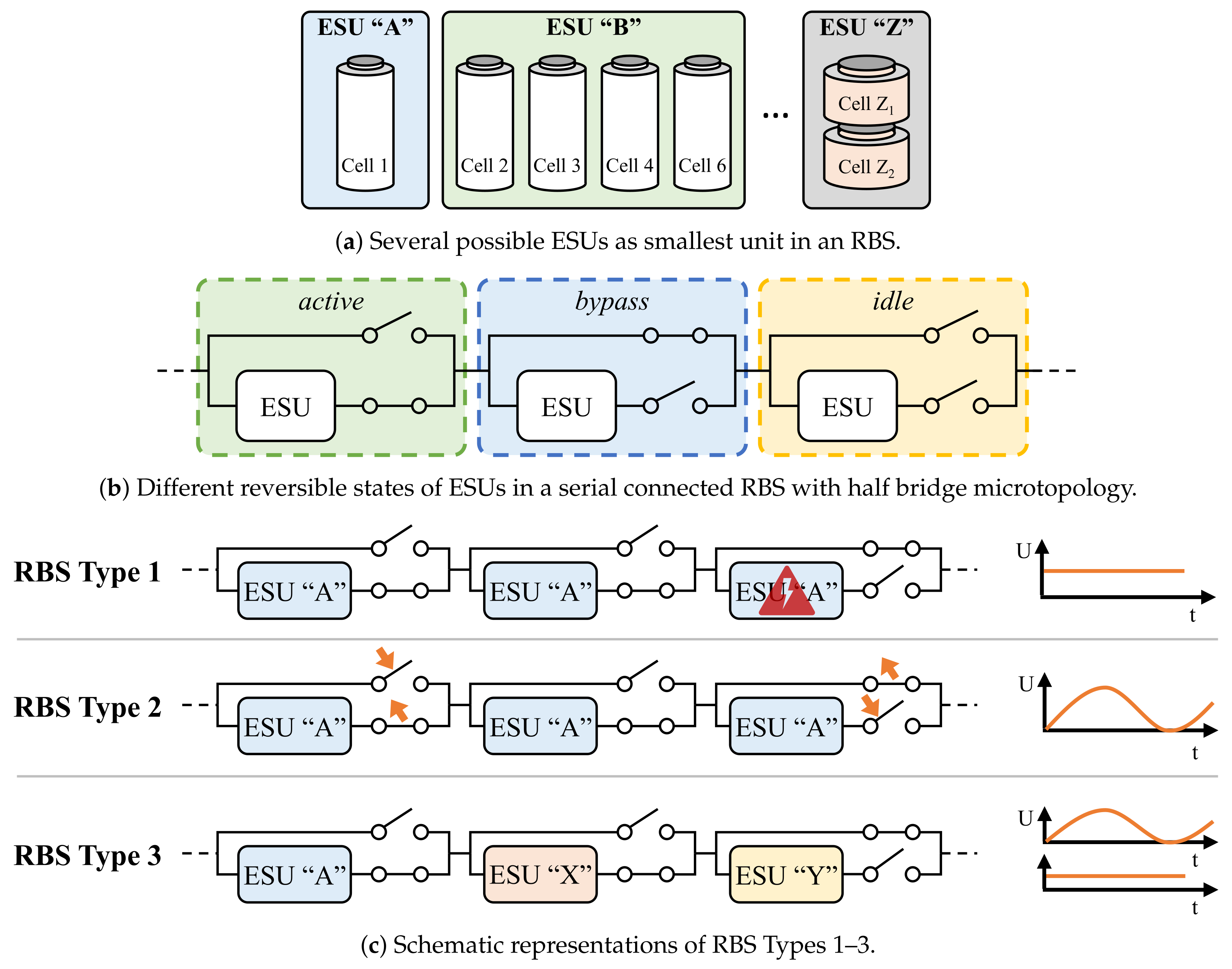
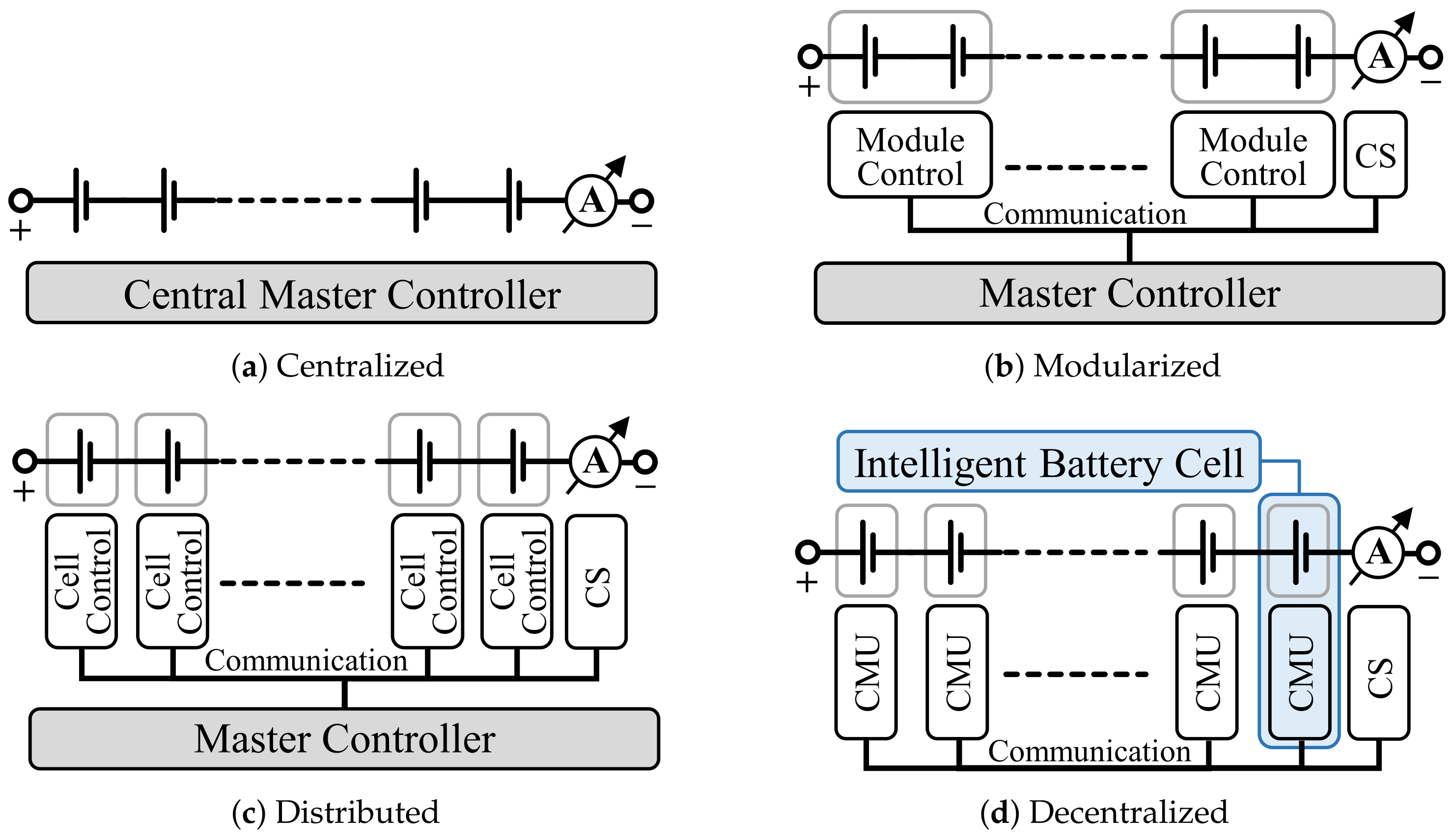
| Sensor Fault | Actuator Fault | |||||||
|---|---|---|---|---|---|---|---|---|
| Voltage | Current | Temperature | Connection | Cooling System | ||||
| Model-Based | Particle Filter | [46,47] | [46,47] | [46] | ||||
| Kalman Filter | [32,48,49,50,51,52,53] | [32,48,49,50,51,52,53] | [32,51] | [32,54] | ||||
| Luenberger Observer | [55] | |||||||
| Lyapunov-Analysis Nonlinear Observer | [56] | |||||||
| Partial-Differential-Equation Observer | [57] | |||||||
| Proportional Integral Observer | [58] | |||||||
| Sliding Mode Observer | [59] | [59] | [59] | [54] | ||||
| Recursive Least Squares | [25,46,49] | [25,46,49] | [46] | [60] | ||||
| Parity space: Nonlinear Parity Equations | [33,61] | [33,61] | [33,61] | [61] | ||||
| Structural Analysis | [32,34,51,62,63] | [32,34,51,62,63] | [32,34,51,62,63] | [32,34] | [62,63] | |||
| Data-Driven | Wavelet Transform | |||||||
| Correlation Coefficient | [37] | [37] | ||||||
| Shannon Entropy/Mutual Information | [30,64,65,66,67] | |||||||
| Sensor Topology | [35,36,37] | [37] | ||||||
| Incremental Capacity Analysis | ||||||||
| CCCV Transform | ||||||||
| Clustering | [68] | |||||||
| Anomaly Detection | [38] | [38] | [38] | |||||
| Neural Network | ||||||||
| Short Circuit | Accelerated Degradation | ||||||||||||||||
|---|---|---|---|---|---|---|---|---|---|---|---|---|---|---|---|---|---|
| Internal Fault | Overcharge | Overdischarge | Short Circuit | ISC | ESC | Thermal Fault | Accelerated Degradation | Resistance | Capacity | ||||||||
| Model-Based | |||||||||||||||||
| Particle Filter | [45] | ||||||||||||||||
| Kalman Filter | [43,44] | [43,44] | [32,69,70,71] | [32] | |||||||||||||
| Luenberger Observer | [55] | [72] | |||||||||||||||
| Lyapunov-Analysis Nonlinear Observer | [56] | ||||||||||||||||
| Partial-Differential-Equation Observer | [57] | ||||||||||||||||
| Proportional Integral Observer | [73] | [74] | |||||||||||||||
| Sliding Mode Observer | |||||||||||||||||
| Recursive Least Squares | [70,71,75,76,77,78] | [60] | |||||||||||||||
| Parity Space: Nonlinear Parity Equations | |||||||||||||||||
| Structural Analysis | [32,34] | [32,34] | |||||||||||||||
| Data-Driven | |||||||||||||||||
| Wavelet Transform | [79] | [80] | |||||||||||||||
| Correlation Coefficient | [81] | [81,82] | [37,69,81,82] | [37,81,82] | |||||||||||||
| Shannon Entropy/Mutual Information | [83,84] | [64] | [64] | [64] | [85] | [86] | |||||||||||
| Sensor Topology | [35,36] | [37] | [37] | ||||||||||||||
| Incremental Capacity Analysis | [40,41,42] | ||||||||||||||||
| CCCV Transform | [79] | ||||||||||||||||
| Clustering | [87] | [87] | [87] | [87] | [88,89] | ||||||||||||
| Anomaly Detection | [87] | [87] | [38,87] | [39] | [87,90] | [88,89] | |||||||||||
| Artificial Neural Network | [91] | ||||||||||||||||
| Knowledge-Based | |||||||||||||||||
| Rule-Based | [92] | [93] | [94] | ||||||||||||||
| Fuzzy Logic | [95,96] | [95,96] | [95] | ||||||||||||||
| Random Forests Classifier | [97] | ||||||||||||||||
| Artificial Neural Network | [98] | ||||||||||||||||
| Features | Frequencies | Cell | |||||||
|---|---|---|---|---|---|---|---|---|---|
| f | |||||||||
| Beelen et al. [138,139] | |||||||||
| x | x | 50 | 90 LFP | ||||||
| Beelen et al. [143] | x | x | 133/630 | 23 NMC | |||||
| Carkhuff et al. [149] | x | Ano.: 70 | N/A | ||||||
| Cath.: 10 | |||||||||
| Haussmann et al. [150] | x | 500 | 26 N/A | ||||||
| Morello et al. [151] | x | 1 | 34 NMC | ||||||
| Raijmakers et al. [144,145,147] | x | 300–400 | LFP, NCA, 90 LFP | ||||||
| Raijmakers et al. [145,147] | x | 1.6–2 | 90 LFP | ||||||
| Ranieri et al. [146] | x | 80 –2 | 12 NCA | ||||||
| Richardson et al. [120,135] | x | 215 | LFP | ||||||
| Richardson et al. [152] | x | 215 | LFP | ||||||
| Schmidt et al. [153] | x | 2 LCO & NCA | |||||||
| Schwarz et al. [154] | x | 1 | 20 LTO | ||||||
| Socher et al. [148] | N/A | N/A | 21 Ah NMC | ||||||
| Spinner et al. [155] | x | 300 | Ah LCO | ||||||
| Srinivasan et al. [133,136] | x | 40 | Ah LFP, Ah N/A, 50 Ah LCO | ||||||
| Srinivasan et al. [137] | x | 5 | 50 Ah LCO, Ah N/A, 3 Ah N/A | ||||||
| Wang L. et al. [156] | x | 12/44/79 | Ah LFP | ||||||
| Wang X. et al. [157] | x | 8 Ah LFP | |||||||
| Wang X. et al. [158] | x | 10 | 8 Ah LFP, 40 Ah LFP | ||||||
| Zhu et al. [140] | x | 10–100 | 8 Ah N/A | ||||||
| x | 600 –17 | 8 Ah N/A | |||||||
| Zhu et al. [141] | x | 10 | 30 Ah LFP | ||||||
| Modeling Approach | Feature | Methods | ||||||||||||||
|---|---|---|---|---|---|---|---|---|---|---|---|---|---|---|---|---|
| Physical | SPM | ECM | Data-Driven | Capacity | Other | Observer | ANN | SVR | DVA/ICA | EIS | Other | |||||
| Troeltzsch et al. [230] | x | x | x | x | ||||||||||||
| Lee et al. [226] | x | x | x | |||||||||||||
| Haifeng et al. [217] | x | x | DKF | |||||||||||||
| Chiang et al. [235] | x | x | Adaptive O. | |||||||||||||
| Kim et al. [19] | x | x | x | SMO | ||||||||||||
| Plett et al. [236] | x | x | WTLS | |||||||||||||
| Remmlinger et al. [237] | x | x | RLS | |||||||||||||
| Hu et al. [174] | x | x | DKF | |||||||||||||
| Rahimian et al. [238] | x | LAM | EKF/UKF | |||||||||||||
| Andre et al. [192] | x | x | x | |||||||||||||
| Feng et al. [227] | x | x | x | Point Counting | ||||||||||||
| Kim et al. [189] | x | x | x | |||||||||||||
| Nuhic et al. [239] | x | x | x | |||||||||||||
| Prasad et al. [222] | x | x | Diffusion Time | LS | ||||||||||||
| Remmlinger et al. [240] | x | x | KF | |||||||||||||
| Schwunk et al. [241] | x | x | PF | |||||||||||||
| Weng et al. [242] | x | x | x | x | ||||||||||||
| Zheng et al. [243] | x | x | GA | |||||||||||||
| Eddahech et al. [225] | x | CVCT | Empirical | |||||||||||||
| Guo et al. [223] | x | CCCT | NLS | |||||||||||||
| Han et al. [244] | x | x | Calibrated O. | |||||||||||||
| Hu et al. [245] | x | Sample Entropy | Empirical | |||||||||||||
| Kim et al. [80] | x | DWT | Empirical | |||||||||||||
| Zou et al. [185] | x | x | DKF | |||||||||||||
| Berecibar et al. [246] | x | x | x | |||||||||||||
| Wu et al. [247] | x | x | x | |||||||||||||
| Zou et al. [186] | x | x | EKF | |||||||||||||
| Dubarry et al. [248] | x | LAM, LLI | Empirical | |||||||||||||
| Gong et al. [233] | x | Gas Production | Empirical | |||||||||||||
| Huhman et al. [231] | x | x | x | |||||||||||||
| Sanchez et al. [249] | Vessel Model | x | Fuzzy | |||||||||||||
| Cai et al. [250] | x | DWT | Empirical | |||||||||||||
| Chen et al. [251] | x | x | RF | |||||||||||||
| Lajara et al. [232] | x | x | x | LS | ||||||||||||
| Li et al. [228] | x | x | x | |||||||||||||
| Li et al. [252] | x | x | EKF, PF | |||||||||||||
| Santos et al. [253] | x | x | x | |||||||||||||
| Shen et al. [198] | x | x | RLS | |||||||||||||
| Smiley et al. [254] | x | x | IMM KF | |||||||||||||
| Tang et al. [255] | x | x | x | |||||||||||||
| Wassiliadis et al. [256] | x | x | DEKF | |||||||||||||
| Ganeshan et al. [200] | x | x | x | |||||||||||||
| Yu et al. [257] | x | x | H | |||||||||||||
| Zheng et al. [258] | x | x | DKF | x | Arrhenius | |||||||||||
| Bi et al. [259] | x | x | x | LAM, LLI | PF | |||||||||||
| Jiang et al. [260] | x | x | x | |||||||||||||
| Liebhart et al. [142] | x | x | x | |||||||||||||
| Liu et al. [224] | x | x | CVCT, CCCT | Empirical | ||||||||||||
| Maletic et al. [190] | x | x | DKF | |||||||||||||
| Meng et al. [104] | x | x | UKF | |||||||||||||
| Shu et al. [261] | x | x | x | x | ||||||||||||
| Xu et al. [262] | x | DWT | Empirical | |||||||||||||
| Yang et al. [263] | x | x | Empirical | |||||||||||||
| Limits | Description | |||||||
|---|---|---|---|---|---|---|---|---|
| U | I | P | SOC | T | Method, Comments, etc. | |||
| Meissner et al. [264] | x | Considers current SOC, SOH and T | ||||||
| Bohlen et al. [268] | x | EIS | ||||||
| Plett et al. [269] | x | x | Bisection Search | |||||
| Kupper et al. [270] | x | x | ECM and Thermal Model | |||||
| Anderson et al. [271] | x | ECM | ||||||
| Bhattacharya et al. [272] | x | Considers Serial and Parallel Strings | ||||||
| Sun et al. [266] | x | x | x | ECM | ||||
| Xiong et al. [273] | x | x | ECM | |||||
| Fleischer et al. [274] | x | x | Fuzzy ANN, considers current SOC, SOH and T | |||||
| Xiong et al. [267] | x | x | x | x | ECM, Time Horizon of 30 s | |||
| Pei et al. [275] | x | x | ECM | |||||
| Sun et al. [188] | x | x | x | ECM | ||||
| Balagopal et al. [276] | x | Binary | ||||||
| Xavier et al. [277] | x | x | Charging Strategy with MPC | |||||
| Burgos-Mellado et al. [278] | x | x | PF based on ECM | |||||
| Dong et al. [279] | x | x | x | ECM | ||||
| Malysz et al. [280] | x | x | x | ECM | ||||
| Shen et al. [198] | x | x | ECM with RLS for Parameter Identification | |||||
| Cell Type | Capacity | Frequency | Operation Mode | Application |
|---|---|---|---|---|
| LCO po | 210 | temporally resolved pulse-receive acoustic TOF measurements | stress induced failure [367] SOC/SOH | |
| LCO po | 200 | transmission mode | SOC/SOH estimation [363] | |
| LFP po | n.a. | n.a. | n.a. | |
| LCO po | 1 | 5 | pulse echo mode through transmission mode | detection of local degradation [368] |
| LCO po | 200 | transmission mode | SOC determination [366] | |
| LCO po | n.a. | pulse echo mode | SOC determination [364] | |
| NCA cy | n.a. | n.a. | through transmission mode | n.a. |
| NMC po | n.a. | in-plane and through-plane modes | mechanical structure during high temperature abuse [369] | |
| NMC po | 100–200 | acousto-ultrasonic guided waves in-plane mode | SOC determination intercalation staging [370] | |
| NMC po | 36 | 200–600 | non-contact air-coupled | SOC determination [371] |
| Microtopology | SS | TS | PR | SB | PA | |
|---|---|---|---|---|---|---|
| Half Bridge [375,381,408,413,433,434,435,436,437,438,439,440,441,442,443] |  | ext | yes | no | ||
| Prior Half Bridge [447] |  | Level 0: 2 Level N: | ext | no | no | |
| Cross-Switched [448] |  | int | no | no | ||
| Cascaded Cross-Switched [449] |  | int | yes | no | ||
| CEBS [450] |  | 4 | int | no | no | |
| Full Bridge [380,385,407,410,418,419,435,451,452,453,454,455,456] |  | int | yes | no | ||
| ECIN [457] |  | int | yes | no | ||
| Marx [458,459,460,461] |  | ext | yes | yes | ||
| MMSPC [416,431,435] |  | int | yes | yes | ||
| M2B [455,462,463] |  | int | yes | yes | ||
| PECIN [464] |  | int | yes | yes | ||
| Requirement | Reasoning |
|---|---|
| Electric Losses | The electric losses should be low in order to increase the overall range of the BEV and to reduce the required cooling capacity. |
| Leakage Current | Should be low to reduce the stand-by consumption. |
| Switching Frequency | For an RBS Type 2, switching frequencies of several kilohertz are appropriate in order to achieve a low harmonic content. In contrast to an RBS Type 2, the switching frequency of a few hertz is sufficient for an RBS Type 1. |
| Blocking Voltage | The necessary blocking voltage of the switch is determined by the used topology of the RBS [531]. The topology proposed by [532] e.g., requires to block the voltage of the whole battery while the cascaded half-bridge for example only needs to block the voltage of a single cell. Additionally, the topology dictates if the switch has to block voltage in both directions (bidirectional) or in only one direction (unidirectional). |
| Current Capability | Since batteries need to be charged and discharged, the switch must be able to conduct current in both directions. This requires either a unipolar device or a combination of two bipolar devices or a bipolar device with a Schottky diode in parallel. Additionally, the switch must be able to conduct the peak current of the application. |
| Requirement | Reasoning |
|---|---|
| Cell Monitoring | To keep the battery cells in a save state, parameters like the cell voltages, temperatures, and currents have to be monitored [558]. |
| Battery Safety and Protection | No battery cell in the pack may exceed a safety critical limit regarding voltage and temperature [558]. |
| Estimation of SOC, SOH, and SOF | SOC, SOH, and SOF are important indicators of battery systems and serve as basis for functionalities like range prediction, balancing, etc. [554]. |
| Ensure the Isolation | The BMS must guarantee the isolation between the HV and the rest of the vehicle. |
| Balancing | To increase the total usable capacity of the battery pack, charge imbalances between serial cells must be compensated [554,559]. |
| Charge Control | The batteries have limitations for the charge current. They have to be considered during the charging process. Advanced charging strategies (e.g., pulse charging) may be applied. |
| Thermal Management | For safety reason, but also to increase the efficiency, the battery must be operated in an optimal temperature range. For this purpose, it can be cooled as well as heated. |
| Communication with the Car | The BMS is responsible for sharing important parameters like the SOC of the battery with the other vehicle’s components. Furthermore, power requirements of the drive train are received. |
| Open Main Switch | In emergency case or when the vehicle is parked the BMS opens the main switch. |
| Control RBS switches | A significant number of switches are controlled to reconfigure the ESUs. Depending on the RBS type and its functionality, the switching operation must be performed with high synchronicity. |
Publisher’s Note: MDPI stays neutral with regard to jurisdictional claims in published maps and institutional affiliations. |
© 2021 by the authors. Licensee MDPI, Basel, Switzerland. This article is an open access article distributed under the terms and conditions of the Creative Commons Attribution (CC BY) license (https://creativecommons.org/licenses/by/4.0/).
Share and Cite
Komsiyska, L.; Buchberger, T.; Diehl, S.; Ehrensberger, M.; Hanzl, C.; Hartmann, C.; Hölzle, M.; Kleiner, J.; Lewerenz, M.; Liebhart, B.; et al. Critical Review of Intelligent Battery Systems: Challenges, Implementation, and Potential for Electric Vehicles. Energies 2021, 14, 5989. https://doi.org/10.3390/en14185989
Komsiyska L, Buchberger T, Diehl S, Ehrensberger M, Hanzl C, Hartmann C, Hölzle M, Kleiner J, Lewerenz M, Liebhart B, et al. Critical Review of Intelligent Battery Systems: Challenges, Implementation, and Potential for Electric Vehicles. Energies. 2021; 14(18):5989. https://doi.org/10.3390/en14185989
Chicago/Turabian StyleKomsiyska, Lidiya, Tobias Buchberger, Simon Diehl, Moritz Ehrensberger, Christian Hanzl, Christoph Hartmann, Markus Hölzle, Jan Kleiner, Meinert Lewerenz, Bernhard Liebhart, and et al. 2021. "Critical Review of Intelligent Battery Systems: Challenges, Implementation, and Potential for Electric Vehicles" Energies 14, no. 18: 5989. https://doi.org/10.3390/en14185989