
Influence of Driving Direction on the Stability of a Group of Headings Located in a Field of High Horizontal Stresses in the Polish Underground Copper Mines †


Abstract
:1. Introduction
- −
- interaction of individual tectonic units,
- −
- the terrain surface,
- −
- tectonic features of the rock mass,
- −
- depth of the rock mass, and
- −
- stiffness of rock material, expressed, among others through Poisson’s ratio ν and the modulus of linear deformation (longitudinal modulus of elasticity) E.
- −
- roof bedding (vertical split),
- −
- concentration of mineralized foigs,
- −
- fault concentration,
- −
- average fault throw, and
- −
- tensile strength of the roof rock beam.
- −
- excavation height is greater than 4.5 m (regardless of the inclination angle of the side walls) or
- −
- excavation height is not greater than 4.5 m and moving the side walls outwards by approximately 10° is not possible.
2. In-Situ Tests of Stresses in the Polkowice–Sieroszowice Mine
- −
- measurement point 1: located in the “Sieroszowice I” mine area, between crosscuts 13 and 12 in main haulage roadway T-360, at a depth of 966.0 m below ground level;
- −
- measurement point 2: located in division G-62, in main haulage roadway T-357, in the vicinity of crosscut P-84; and
- −
- measurement point 3: located in the “Sieroszowice I” mine area, in the recess of main incline E-1, in the vicinity of crosscut 63, at a depth of 906.0 m below ground level.
- −
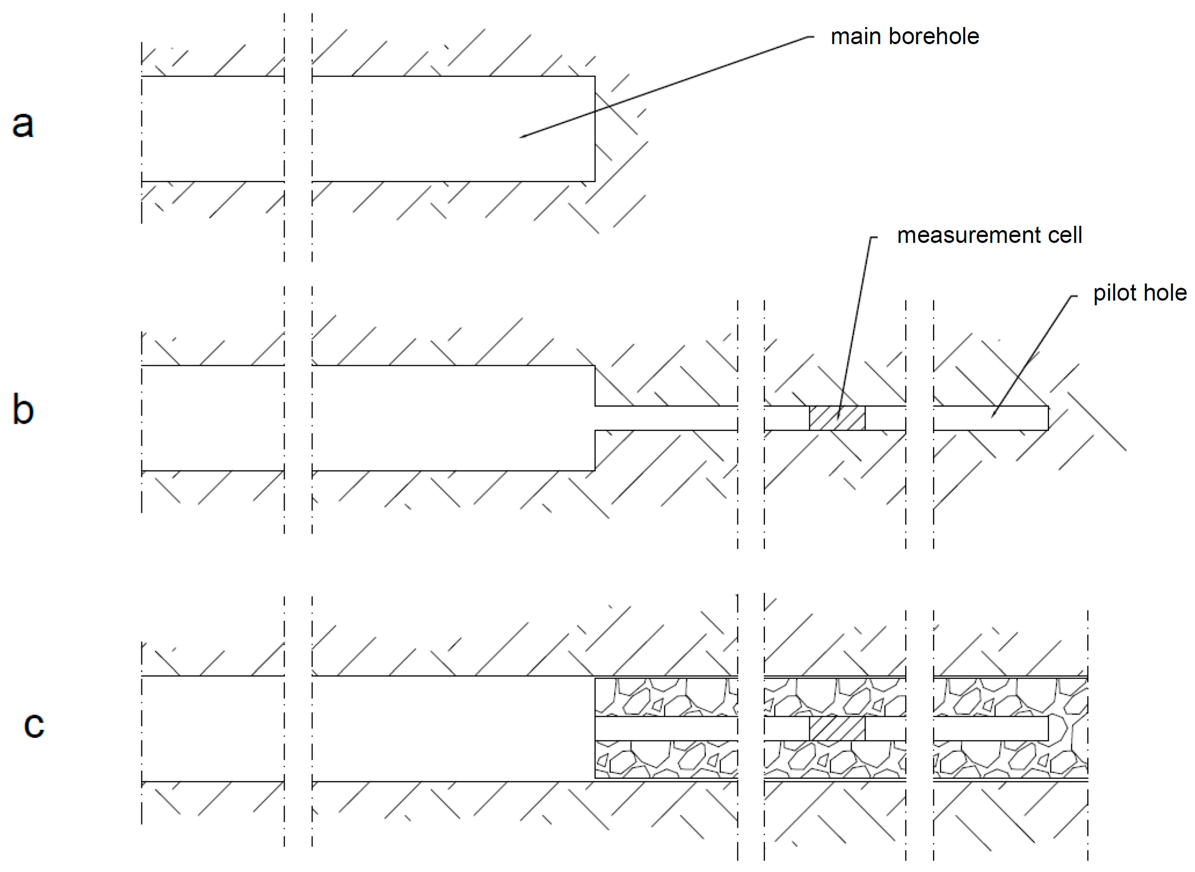
- boring a hole in the rock which has a large-diameter (60–220 mm) and a length sufficient to treat the influence of the mining excavation as negligible (Figure 3a),
- −
- driving a pilot hole typically 38 mm in diameter (Figure 3b),
- −
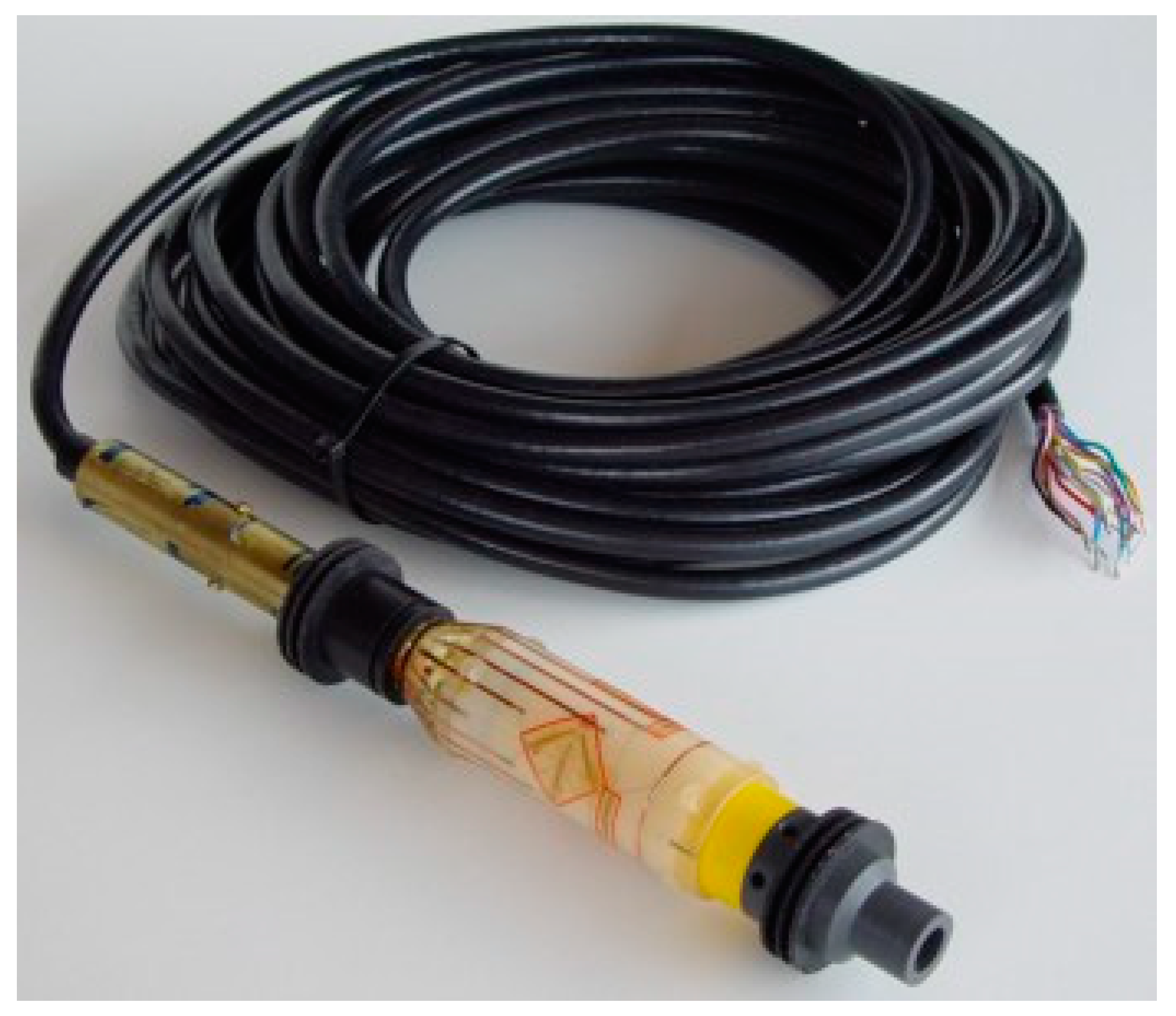
- placing a measurement device (probe) in the pilot hole, and
- −
- effecting stress relief in the cut-out cylinder, whose deformations are recorded with a measurement device (Figure 3c).
3. Stability Prediction for a Group of Headings at the Polkowice-Sieroszowice Mine
- −
- dividing an area into subareas,
- −
- determining FEM equations for the elements,
- −
- gluing (aggregating) the elements,
- −
- allowing for boundary conditions,
- −
- solving the equations, and
- −
- calculating additional values in other (than nodes) points of the area [22].
- −
- uniaxial tensile strength of the rock mass σt,
- −
- cohesion c,
- −
- internal friction angle φ, and
- −
- rock mass modulus of elasticity Erm.
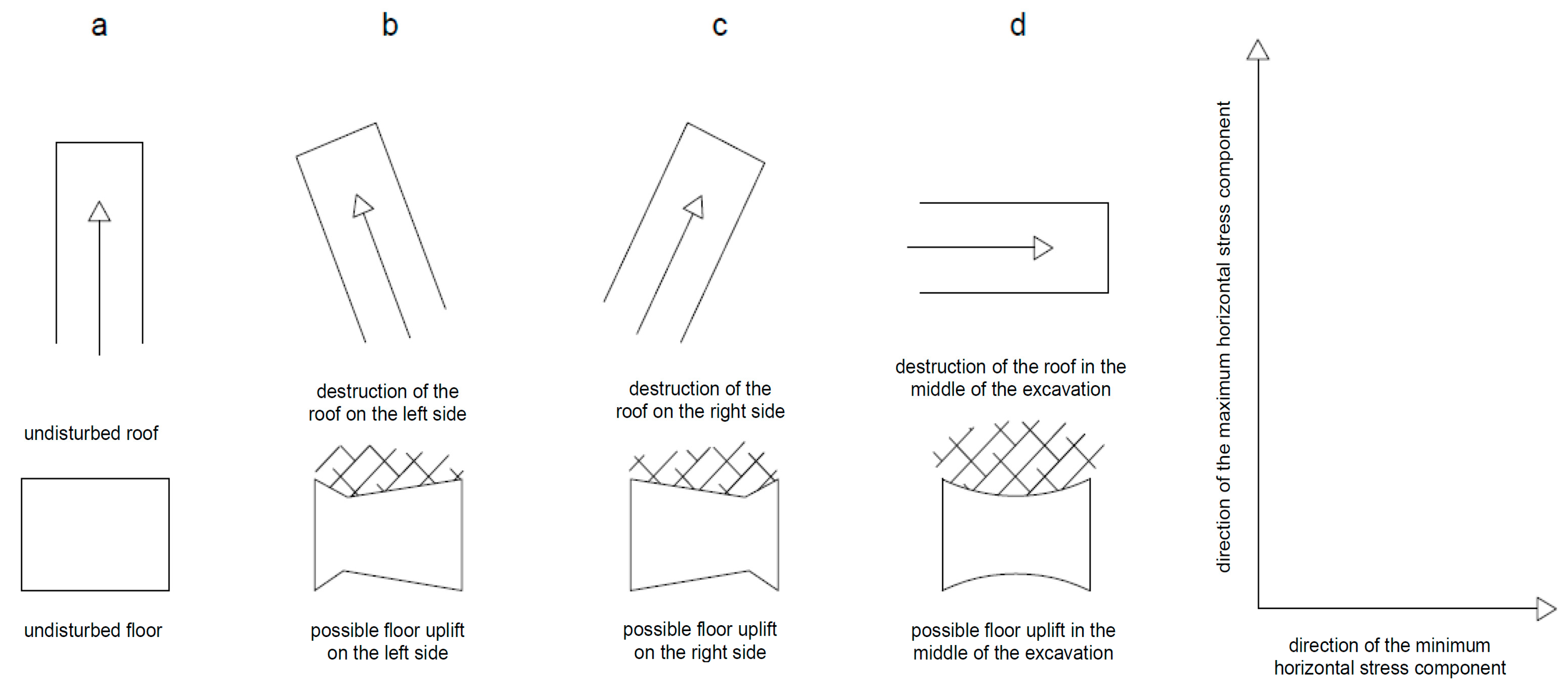
- load variant 1 (maximum horizontal stress component σH is in the direction parallel to the longer axis of the headings):
- −
- side edges: px = 26.10 MPa,
- −
- upper edge and bottom edge: pz = 27.70 MPa,
- −
- direction perpendicular to plate surface: py = 32.20 MPa,
- load variant 2 (maximum horizontal stress component σH is in the direction perpendicular to the longer axis of the headings):
- −
- side edges: px = 32.20 MPa,
- −
- upper edge and bottom edge: pz = 27.70 MPa,
- −
- direction perpendicular to plate surface: py = 26.10 MPa.
- −
- distribution of principal stresses σ1,
- −
- distribution of principal stresses σ3,
- −
- horizontal stress distribution σxx,
- −
- vertical stress distribution σyy,
- −
- total displacements,
- −
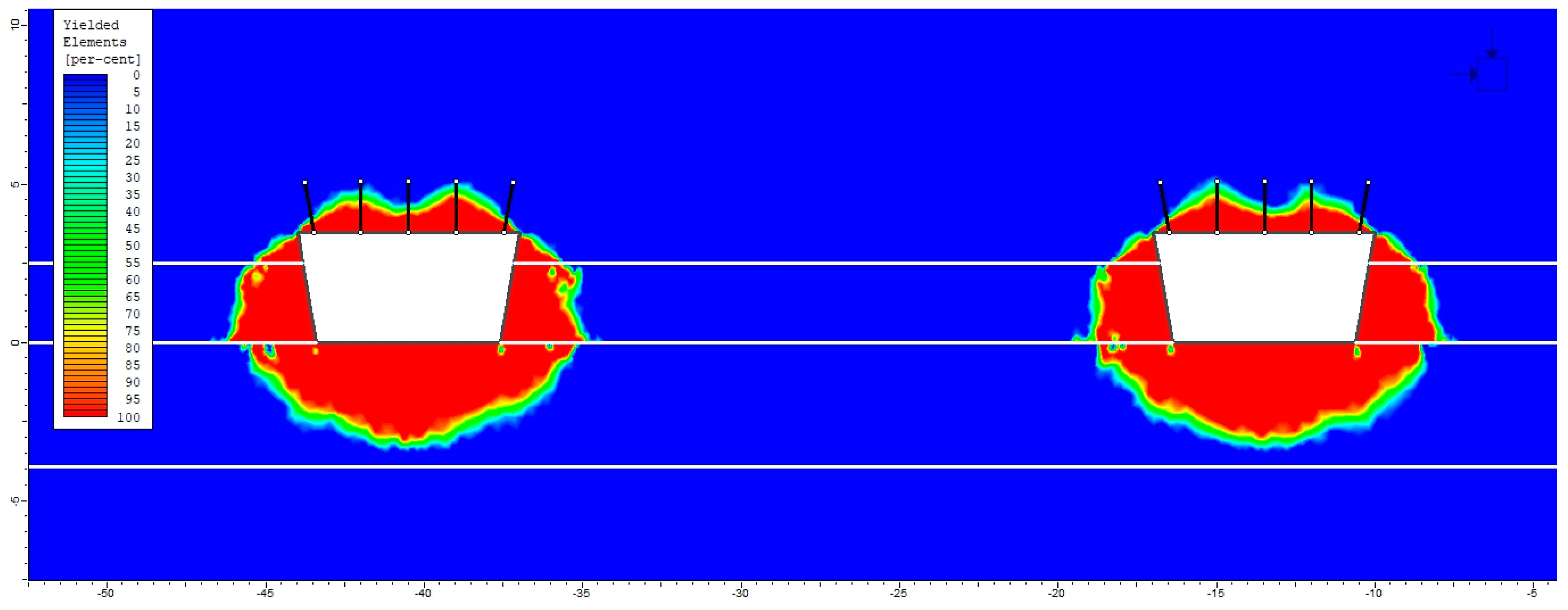
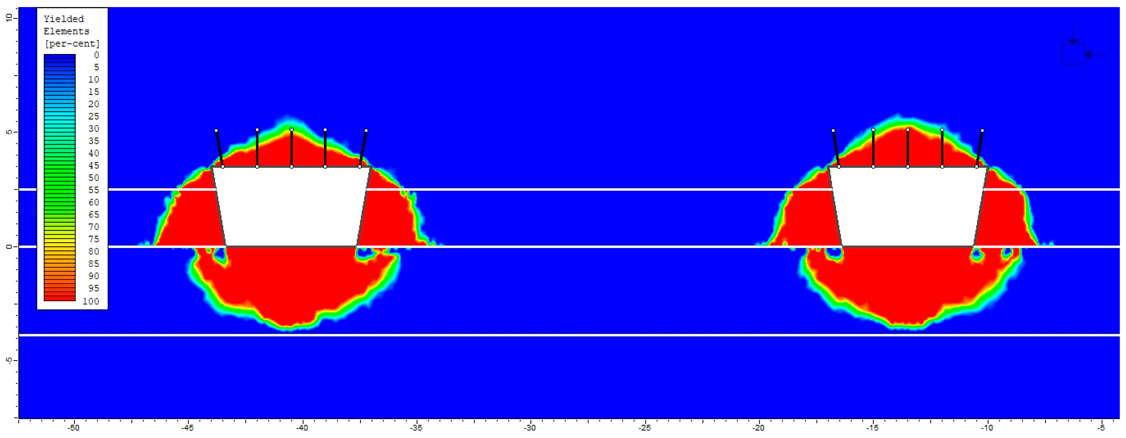
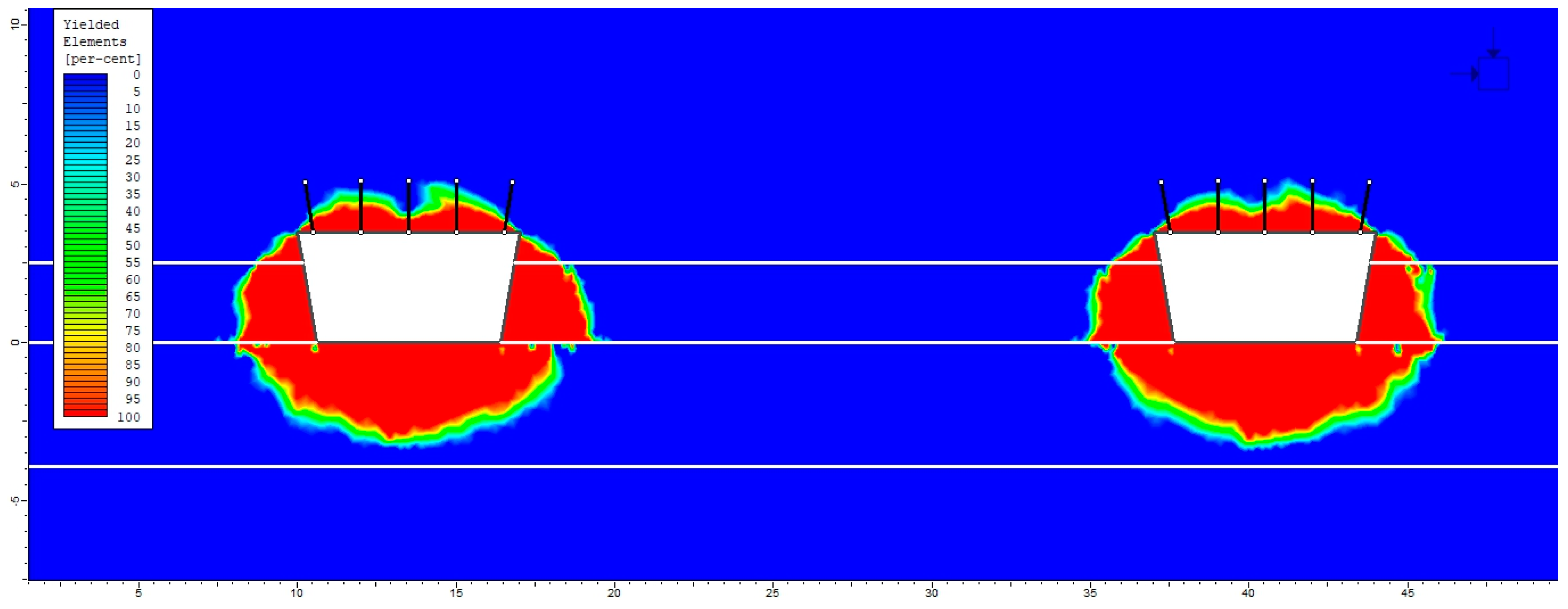
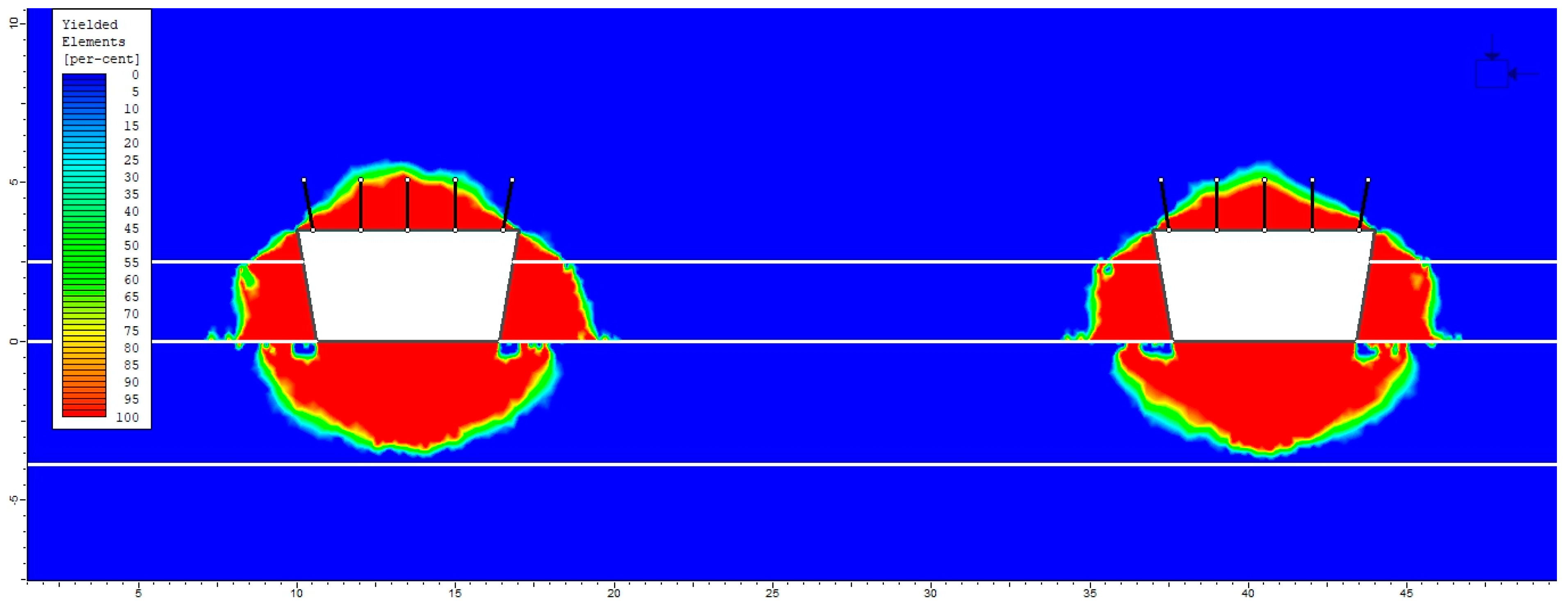
- yielded element area (yielded rock mass zone).
4. Results of Numerical Simulations and Selection of the Bolting System
- −
- the direction in which headings are driven in a field of high horizontal stresses may be of key importance to the stability of headings in the LGCB mines, and
- −
- problems with stability may occur when the yielded rock zone in the roof is larger than the bolted zone.
- −
- The surface of the relaxed area around a heading increases together with the increase of the horizontal stress in the rock mass (high stress field in the rock mass). Meanwhile, stress concentration in the analyzed headings occurs only in the corners of the roofs and of the side walls.
- −
- The greatest total displacements occur in the floors of the analyzed headings (formed of sandstones having low strength and strain parameters). The range of the zone affected by displacements increases together with the increase of horizontal stresses in the rock mass.
- −
- The surface of the yielded area in the rock mass around headings driven in the heading group increases together with the increase of horizontal stresses in the rock mass (high stress field in the rock mass). This phenomenon is strictly related to the stress and strain parameters of the rock layers surrounding the excavations and negatively influences their stability.
- −
- The verification of the results of the numerical simulations obtained for the plastic-elastic model with rock softening confirmed that they correspond most accurately to the observed cases of stability losses in the mining excavations of Polish copper mines.
- −
- in the case of a group of headings driven parallel to the direction of the maximum horizontal stress component σH, the bolts were 1.6 m in length and the bolting pattern (distance between the bolts) was 1.5 × 1.5 m,
- −
- and in the case of a group of headings driven perpendicular to the direction of the maximum horizontal stress component σH, the bolts were 2.2 m in length and the bolting pattern (distance between the bolts) was 1.5 × 1.5 m,
5. Conclusions
Author Contributions
Funding
Institutional Review Board Statement
Informed Consent Statement
Data Availability Statement
Conflicts of Interest
References
- Hast, N. The state of stresses in the upper part of the earth’s crust. Eng. Geol. 1967, 2, 5–17. [Google Scholar] [CrossRef]
- Mark, C. Horizontal stress and its effects on longwall ground control. Min. Eng. 1991, 11, 1356–1360. [Google Scholar]
- Daws, G.; Hons, B. Roof bolting in coal mining—Design and implementation. Min. News 1992, 1, 27–32. (In Polish) [Google Scholar]
- Mark, C.; Mucho, T.P. Longwall Mine Design for Control of Horizontal Stress, New Technology for Longwall Ground Control; US Government Printing Office: Washington, DC, USA, 1994; pp. 53–73.
- Mark, C.; Mucho, T.P.; Dolinar, D. Horizontal stress and longwall headgate ground control. Min. Eng. 1998, 61–68. [Google Scholar]
- Mark, C. Focus on Ground Control: Horizontal Stress. Coal Age 2001, 106, 47–50. [Google Scholar]
- Agapito, J.; Gilbride, L. Horizontal stresses as indicators of roof stability. In Proceedings of the SME Annual Meeting, Phoenix, AZ, USA, 25–27 February 2002. [Google Scholar]
- Heidbach, O.; Tingay, M.; Barth, A.; Reinecker, J.; Kurfeß, D.; Müller, B. Global stress pattern based on the World Stress Map database release. Tectonophysics 2008, 482, 3–15. [Google Scholar] [CrossRef] [Green Version]
- Trinh, N.; Jonsson, K. Design considerations for an underground room in a hard rock subjected to a high horizontal stress field at Rana Gruber, Norway. Tunn. Undergr. Space Technol. 2013, 38, 205–212. [Google Scholar] [CrossRef]
- Zhaoa, X.G.; Wanga, J.; Caib, M.; Maa, L.K.; Zonga, Z.H.; Wanga, X.Y.; Sua, R.W.; Chena, M.; Zhaoa, H.G.; Chenc, Q.C.; et al. In-situ stress measurements and regional stress field assessment of the Beishan area, China. Eng. Geol. 2013, 163, 26–40. [Google Scholar] [CrossRef]
- Haghi, A.H.; Kharrat, R.; Asef, M.R. A case study for HCL-based fracturing and stress determination: A Deformation/Diffusion/Thermal approach. J. Petrol. Sci. Eng. 2013, 112, 105–116. [Google Scholar] [CrossRef]
- Haghi, A.H.; Chalaturnyk, R.; Ghobadi, H. The state of stress in SW Iran and implications for hydraulic fracturing of a naturally fractured carbonate reservoir. Int. J. Rock. Mech. Min. Sci. 2018, 105, 28–43. [Google Scholar] [CrossRef]
- Salmachi, A.; Rajabi, M.; Wainman, C.; Mackie, S.; McCabe, P.; Camac, B.; Clarkson, C. History, Geology, In Situ Stress Pattern, Gas Content and Permeability of Coal Seam Gas Basins in Australia: A Review. Energies 2021, 14, 2651. [Google Scholar] [CrossRef]
- Fabjanczyk, M.; Bryja, Z.; Bugajski, W.; Katulski, A. Measurement of pre-exploitation stress field in KGHM Polska Miedz, O/ZG Rudna. Proc. Undergr. Min. School 1997, 1, 67–75. (In Polish) [Google Scholar]
- Fabich, S.; Lis, J.; Pytel, W.; Szadkowski, T.; Szlązak, M. Calculation of Stress in Rock Mass in Various Geological and Mining Conditions on the Basis of In-Situ Measurements, Stage I: Development of Technologies Allowing the Measurement of Primary and Production Stress Tensor in the Rock Mass, and Completing the First Stage of Measurements; Cuprum R&D Centre: Wroclaw, Poland, 2003. (In Polish) [Google Scholar]
- Butra, J. (Ed.) Magnitude and Directions of In-Situ Stress in the Deep Part of a Copper ore Deposit with an Appendix “Determination of the Impact of the Primary Stress Directions and Magnitudes on the Optimal Geometry of Mining Fields; KGHM Cuprum sp. z o.o. R&D Centre: Wroclaw, Poland, 2012. (In Polish) [Google Scholar]
- Kidybiński, A. Basics of Mining Geotechnics; Slask: Katowice, Poland, 1982. [Google Scholar]
- Ming, J.; Hongjun, G. Influence of in-situ rock stress on the stability of roadway surrounding rock: A case study. J. Geophys. Eng. 2020, 17, 138–147. [Google Scholar] [CrossRef]
- Esterhuizen, G.S.; Dolinar, D.R.; Iannacchione, A. Field observations and numerical studies of horizontal stress effects on roof stability in US limestone mines. J. S. Afr. Inst. Min. Metall. 2008, 108, 345–352. [Google Scholar]
- Abdel-Meguid, M.; Rowe, R.K.; Lo, K.Y. Three-dimensional analysis of unlined tunnels in rock subjected to high horizontal stress. Can. Geotech. J. 2003, 40, 6. [Google Scholar] [CrossRef] [Green Version]
- Li, H.; Lin, B.; Hong, Y.; Gao, Y.; Yang, W.; Liu, T.; Wang, R.; Huang, Z. Effects of in-situ stress on the stability of a roadway excavated through a coal seam. Intern. J. Min. Sci. Technol. 2017, 27, 917–927. [Google Scholar] [CrossRef]
- Pawelus, D. Influence of Horizontal Stress on the Stability of Underground Excavations in Copper Mines. Ph.D. Thesis, Wroclaw University of Science and Technology, Wroclaw, Poland, 2010. (In Polish). [Google Scholar]
- Cała, M.; Flisiak, J.; Tajduś, A. Mechanism of Engagement between Bolts and Rock Mass of Various Formation; Library of Undergr. Min. School: Krakow, Poland, 2001. (In Polish) [Google Scholar]
- Collaborative Publication. Instructions on Determining the Geomechanical Parameters of Roof Rocks with Respect to Roof Classes in Copper Mines, as Required in the Selection of a Roof Bolt System Design; KGHM Polska Miedz S.A.: Lubin, Poland, 2017. (In Polish) [Google Scholar]
- Collaborative Publication. Regulations on the Selection, Construction and Control of Excavation Support in the KGHM Polska Miedz S.A. Mines; KGHM Polska Miedz S.A.: Lubin, Poland, 2017. (In Polish) [Google Scholar]
- Pawelus, D. Stability assessment of headings situated in a field of high horizontal stress in Polish copper mines by means of numerical methods. In IOP Conference Series—Earth & Environmental Science, Proceedings of the World Multidisciplinary Earth Sciences Symposium, Prague, Czech Republic, 3–7 September 2018; IOP Publishing Ltd.: Bristol, UK, 2019; Volume 221, p. 221. [Google Scholar]
- Pawelus, D. The azimuths difference method as an effective method of determining the value of horizontal stress acting on mining excavations in underground mines. In Science and Technologies in Geology, Exploration and Mining 1.3, Exploration and Mining, Proceedings of the 18th International Multidisciplinary Scientific GeoConference, Albena, Bulgaria, 2–8 July 2018; Curran Associates, Inc.: New York, NY, USA, 2018; Volume 18, p. 18. [Google Scholar]
- Amadei, B.; Stephansson, O. Rock Stress and Its Measurement; Chapman & Hall: London, UK, 2009. [Google Scholar]
- Hoek, E.; Carranza-Torres, C.T.; Corkum, B. Hoek-Brown failure criterion—2002 edition. In Proceedings of the North American Rock Mechanics Society Meeting, Toronto, ON, Canada, 7–10 July 2002. [Google Scholar]
- Hoek, E. Strength of rock and rock masses. ISRM News J. 1994, 2, 4–16. [Google Scholar]
- Hoek, E.; Brown, E.T. Practical estimates of rock mass strength. Int. J. Rock Mech. Min. Sci. 1997, 34, 1165–1186. [Google Scholar] [CrossRef]
- Hoek, E.; Marinos, P. GSI: A geologically friendly tool for rock mass strength estimation. In Proceedings of the ISRM International Symposium, Melbourne, Australia, 19–24 November 2000. [Google Scholar]


| Measurement Test No. | Stress Field Parameters | ||||
|---|---|---|---|---|---|
| σH [MPa] | αH [°] | σh [MPa] | αh [°] | σv [MPa] | |
| SP1T2 | 29.9 | 160.0 | 22.3 | 70.0 | 27.7 |
| SP1T3 | 29.9 | 157.0 | 24.4 | 67.0 | 27.9 |
| SP1T4 | 20.6 | 158.0 | 16.9 | 68.0 | 22.7 |
| SP2T2 | 32.2 | 6.0 | 26.1 | 96.0 | 27.7 |
| SP3T2 | 27.7 | 156.0 | 14.5 | 66.0 | 27.6 |
| SP3T3 | 19.2 | 139.0 | 12.8 | 49.0 | 18.2 |
| Location | Rock Type | h [m] | ρ [kg/dm3] | Rc [MPa] | Rr [MPa] | Ei [GPa] | v [–] |
|---|---|---|---|---|---|---|---|
| Roof | Anhydrite | 16.00 | 2.94 | 92.16 | 6.69 | 53.22 | 0.26 |
| Calcareous dolomite II | 9.00 | 2.82 | 236.10 | 14.59 | 113.17 | 0.25 | |
| Excavation | Calcareous dolomite I | 0.50 | 2.47 | 98.43 | 6.04 | 38.77 | 0.26 |
| Streaky dolomite | 0.90 | 2.77 | 140.57 | 9.33 | 40.73 | 0.24 | |
| Clay dolomite | 0.55 | 2.63 | 79.50 | 5.70 | 28.75 | 0.23 | |
| Quartz sandstone IV | 0.25 | 2.40 | 39.97 | 2.78 | 16.53 | 0.19 | |
| Quartz sandstone III | 0.30 | 2.25 | 16.57 | 0.80 | 7.23 | 0.13 | |
| Floor | Quartz sandstone II | 3.90 | 2.07 | 20.67 | 1.22 | 8.63 | 0.14 |
| Quartz sandstone I | 1.10 | 2.02 | 16.95 | 0.75 | 6.65 | 0.12 |
| Location | Rock Type | σt [MPa] | c [MPa] | ϕ [°] | Erm [MPa] |
|---|---|---|---|---|---|
| Roof | Anhydrite | 0.738 | 6.896 | 38.66 | 39,000.37 |
| Calcareous dolomite II | 5.226 | 21.535 | 39.00 | 99,628.96 | |
| Excavation | Calcareous dolomite I | 1.495 | 7.853 | 37.69 | 31,649.89 |
| Streaky dolomite | 3.112 | 12.821 | 39.00 | 35,856.57 | |
| Clay dolomite | 0.828 | 5.653 | 36.31 | 21,068.41 | |
| Quartz sandstone IV | 0.103 | 2.784 | 39.06 | 8595.60 | |
| Quartz sandstone III | 0.043 | 1.154 | 39.06 | 3759.60 | |
| Floor | Quartz sandstone II | 0.053 | 1.439 | 39.06 | 4487.60 |
| Quartz sandstone I | 0.044 | 1.180 | 39.06 | 3458.00 |
| Location | Rock Type | h [m] | Es [MPa] | ν [–] | σt [MPa] | ϕpeak [°] | cpeak [MPa] | ϕdyl [°] | ϕresid [°] | cresid [MPa] |
|---|---|---|---|---|---|---|---|---|---|---|
| Roof | Anhydrite | 16.00 | 39,000.37 | 0.26 | 0.738 | 38.66 | 6.896 | 2.00 | 36.73 | 1.379 |
| Calcareous dolomite II | 9.00 | 99,628.96 | 0.25 | 5.226 | 39.00 | 21.535 | 2.00 | 37.05 | 4.307 | |
| Excavation (h = 3.5 m) | Deposit mined in dolomite-sandstone | 2.50 | 25,184.11 | 0.22 | 1.617 | 38.16 | 7.847 | 2.00 | 36.25 | 1.569 |
| Floor | Quartz sandstone II | 3.90 | 4487.60 | 0.14 | 0.053 | 39.06 | 1.439 | 2.00 | 37.11 | 0.288 |
| Quartz sandstone I | 1.10 | 3458.00 | 0.12 | 0.044 | 39.06 | 1.180 | 2.00 | 37.11 | 0.236 |
| Excavation Height h [m] | Excavation Width Below the Roof dwst [m] | Excavation Width at the Floor dwsp [m] | Mean Excavation Width dwśr [m] | Excavation Surface Area Sr [m2] | Side Wall Inclination Angle α [°] |
|---|---|---|---|---|---|
| 3.5 | 7.0 | 5.8 | 6.4 | 22.4 | 10.0 |
| Excavation | Yield Range in the Roof [m] | Increase of Yield Range in the Roof | ||
|---|---|---|---|---|
| Load Variant 1 | Load Variant 2 | [m] | [%] | |
| 1 | 1.32 | 1.77 | 0.45 | 34.09 |
| 2 | 1.34 | 1.91 | 0.57 | 42.54 |
| 3 | 1.36 | 1.94 | 0.58 | 42.65 |
| 4 | 1.30 | 1.76 | 0.46 | 35.38 |
Publisher’s Note: MDPI stays neutral with regard to jurisdictional claims in published maps and institutional affiliations. |
© 2021 by the authors. Licensee MDPI, Basel, Switzerland. This article is an open access article distributed under the terms and conditions of the Creative Commons Attribution (CC BY) license (https://creativecommons.org/licenses/by/4.0/).
Share and Cite
Adach-Pawelus, K.; Pawelus, D. Influence of Driving Direction on the Stability of a Group of Headings Located in a Field of High Horizontal Stresses in the Polish Underground Copper Mines. Energies 2021, 14, 5955. https://doi.org/10.3390/en14185955
Adach-Pawelus K, Pawelus D. Influence of Driving Direction on the Stability of a Group of Headings Located in a Field of High Horizontal Stresses in the Polish Underground Copper Mines. Energies. 2021; 14(18):5955. https://doi.org/10.3390/en14185955
Chicago/Turabian StyleAdach-Pawelus, Karolina, and Daniel Pawelus. 2021. "Influence of Driving Direction on the Stability of a Group of Headings Located in a Field of High Horizontal Stresses in the Polish Underground Copper Mines" Energies 14, no. 18: 5955. https://doi.org/10.3390/en14185955