Review

A Review on Failure Modes of Wind Turbine Components

by
Abdul Ghani Olabi
1,2,*,
Tabbi Wilberforce
2,
Khaled Elsaid
3,*,
Enas Taha Sayed
4,5,
Tareq Salameh
1,
Mohammad Ali Abdelkareem
1,4,5,* and
Ahmad Baroutaji
6
1
Department of Sustainable and Renewable Energy Engineering, University of Sharjah, Sharjah P.O. Box 27272, United Arab Emirates
2
Mechanical Engineering and Design, School of Engineering and Applied Science, Aston University, Aston Triangle, Birmingham B4 7ET, UK
3
Chemical Engineering Program, Texas A&M University at Qatar, Doha 23874, Qatar
4
Centre for Advanced Materials Research, University of Sharjah, Sharjah P.O. Box 27272, United Arab Emirates
5
Chemical Engineering Department, Faculty of Engineering, Minia University, Minya 61519, Egypt
6
Department of Mechanical Engineering, University of Wolverhampton, Wulfruna St, Wolverhampton WV1 1LY, UK
*
Authors to whom correspondence should be addressed.
Energies 2021, 14(17), 5241; https://doi.org/10.3390/en14175241
Submission received: 26 May 2021 / Revised: 30 July 2021 / Accepted: 5 August 2021 / Published: 24 August 2021

Abstract

:
To meet the increasing energy demand, renewable energy is considered the best option. Its patronage is being encouraged by both the research and industrial community. The main driving force for most renewable systems is solar energy. It is abundant and pollutant free compared to fossil products. Wind energy is also considered an abundant medium of energy generation and often goes hand in hand with solar energy. The last few decades have seen a sudden surge in wind energy compared to solar energy due to most wind energy systems being cost effective compared to solar energy. Wind turbines are often categorised as large or small depending on their application and energy generation output. Sustainable materials for construction of different parts of wind turbines are being encouraged to lower the cost of the system. The turbine blades and generators perform crucial roles in the overall operation of the turbines; hence, their material composition is very critical. Today, most turbine blades are made up of natural fiber-reinforced polymer (NFRP) as well as glass fiber-reinforced polymer (GFRP). Others are also made from wood and some metallic materials. Each of the materials introduced has specific characteristics that affect the system’s efficiency. This investigation explores the influence of these materials on turbine efficiency. Observations have shown that composites reinforced with nanomaterials have excellent mechanical characteristics. Carbon nanotubes have unique characteristics that may make them valuable in wind turbine blades in the future. It is possible to strengthen carbon nanotubes with various kinds of resins to get a variety of different characteristics. Similarly, the end-of-life treatment methods for composite materials is also presented.

1. Introduction

Climate change continues to remain a major issue for both research and industrial communities [1,2]. As the yearly energy demand of the world increases, carbon dioxide emissions increase, as well. This is because fossil products continue to be the main driving force for the energy industry to date [3,4]. The instability of prices for fossil products, coupled with their reserves depleting at a faster pace, has necessitated the urgent need for an alternative form of energy generation [5,6]. Most countries have supported this clarion call by actively formulating policies that seek to expand the renewable energy sources [7,8]. Obviously, the signing of the Kyoto agreement and the Paris agreement by 192 and 197 countries around the world, respectively, is an indication of the massive support for renewable energy as a possible replacement for fossil energy [9,10]. Wind energy, a type of renewable energy sources, is one of the primary energy-generating mediums that can make this goal a reality. Research projects showed that the wind capacity of the EU must annually increase by 21% to achieve the 2020 goal for energy generation. Application of wind energy can be traced to 5000 B.C. when it was used on the river Nile for the sailing of boats. The Babylonians later applied this energy in building the first windmill in 2000 B.C.
The Persians also used wind energy for pumping water as well as crushing in the nineth century. Europe built its first post windmill in the 12th century. In the 19th century, some individuals supported the advancement of this technology. Notable among them were Charles F. Brush, who had researched wind turbines by 1888 [11]. Poul La Cour in 1897 built the first wind turbine in Demark. In 1941, Smith–Putnam developed the first mega sized wind turbine, but the design failed initially, as a turbine blade fell off the system due to poor selection of its material [12].
Studies in the wind turbine industry are performed to enhance the performance of wind turbines. This results in a novel and unique wind turbine blade, which is useful in creating the structure of future wind turbine blades. Currently being investigated is an alternative material system with superior characteristics. The use of this material system in the blade construction results in optimum aerodynamic performance and reduced gravity forces throughout the operational stage, resulting in a longer blade life cycle, overall. In order to meet this need, improved wind blades with sufficient stiffness, strength and prolonged fatigue resistance are needed. Furthermore, the end of life of these blades once they have exhausted their usefulness is very critical, as well. The focus of this review is to present varying materials that can be used for the manufacturing of modern wind turbines and to compare their advantages, disadvantages and uses.

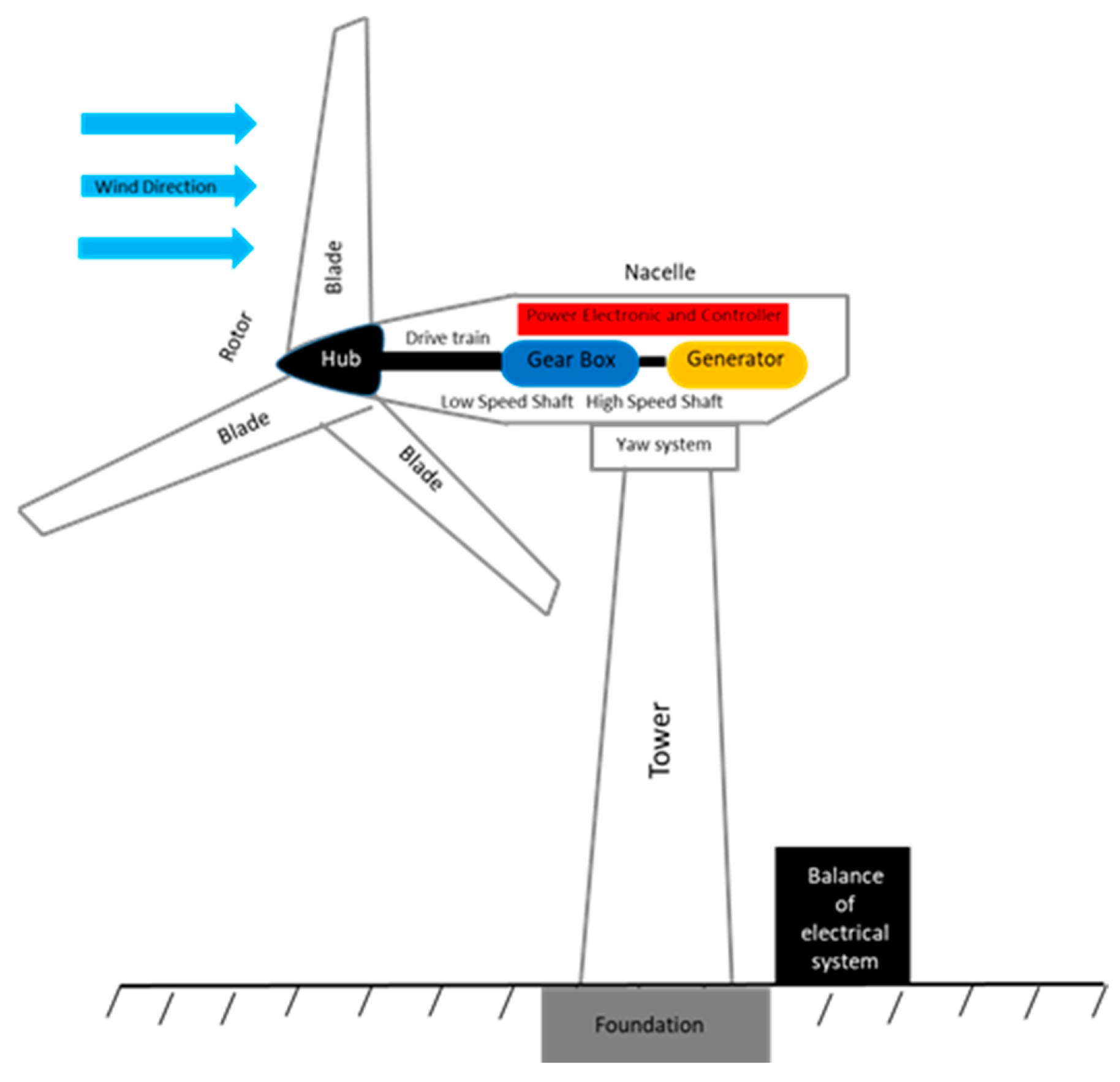
2. Wind Turbine Components

Wind turbines have more than 8000 components, but these components are categorised into six parts shown in Figure 1. The blades, nacelle and tower determine the functionality of the turbines [13]. The tower sits on a concrete foundation, and it supports the blades and the nacelle. The tower is designed to be strong to hold the blade and the nacelle weight. It must also be strong enough to resist any changes in wind velocity around the turbine. Therefore, stiffness and rigidity are the most important material characteristics for designing towers of wind turbines [14]. It is also recommended the tower is built in parts and assembled at the specific location to eliminate or reduce cost. The weight of the turbine tower installed onshore can be slightly lighter compared to turbines installed offshore.
The issue of corrosion also becomes very important and necessary to consider during the design stages of the turbine. Some turbine towers today are made of steel due to the material characteristics of steel. Steel is generally strong and less expensive and has high stiffness [15]. A major challenge in the usage of steel for wind turbine towers is difficulty in welding the components. Most steel towers must be coated to resist the effects of corrosion on the turbine performance and reduce the chances of the turbine falling off, which can be fatal. Researchers today recommend the usage of some type of hybrid steel concrete for wind turbine towers such as that of the glass fiber composite monoliths [16].
The nacelle shown in Figure 1 is the heart of the turbine. Depending on the types of wind turbine (small, medium or large), the nacelle size can vary, but they are often designed to have small space for maintenance purposes. Accessibility to the nacelle for routine maintenance and servicing is also another challenge due to its location on the turbine [17]. Materials for the construction of the nacelle must be light in weight, simple in moulding and able to withstand corrosion. Most nacelle in wind turbines today are made of glass fiber composite material. These turbines are subjected to several bending forces as well as torques. During emergency braking, a large load is applied to the bedplate, causing it to deflect, and this affects the entire drivetrain. Wind turbine engineers suggest that this phenomenon can lead to misalignment of the bedplate and nacelle should this emergency braking continue. Misalignment of the shaft on the drivetrain can lead to wearing out of the bearings, and this will increase maintenance activities on the turbine [18].

3. Wind Turbine Blades

The blade comprises the root, chord, midspan and tip. All these parts support the uplift. A helical vortex is created with the help of the turbine tip. Most turbine roots are designed to be strong to resist different types of stresses due to different wind loadings at varying times [19]. The chord supports the generation of the lift while the midspan handles the bending and shear stresses; these stresses are further transferred from the midspan to the root. Blades of the wind turbines are made up of two faces for both the pressure and suction regions of the area. These faces are linked together using shear webs connecting the upper and the lower regions of the blade [15].
The wind energy sector has seen a surge up in the size of wind turbines. A key factor for this is the need to increase the energy generated by these turbines to meet the world’s high energy consumption. Increasing the turbine size implies that the weight will increase, as well. One design criterion that must be considered as the turbine size is increased is stiffness. This is primarily because, the longer the blade size, the greater the deflection. In order to curb the blades from hitting the tower, stiffness of material for the blade construction is very important. For the wind turbine to exceed its life span (20–25 years), material selection for the various components becomes very vital [20].

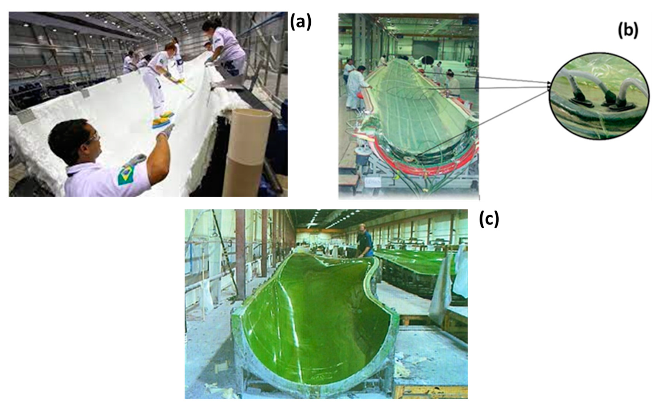
3.1. Wind Turbines Production

The earliest types of wind turbines were produced using wet hand lay-up technology (Figure 2a). Impregnation of the glass fiber was carried out with the aid of rollers and paint brushes. Using an adhesive, the shells were connected to the spars. Small and medium wind turbine blades were manufactured using this method. Webs for larger blades were positioned between the two sides using the same technological approach but with the greater fiber content for the plies [21]. Cost of labour, low quality of the blade and the negative environmental effects were some of the challenges related to using this approach for manufacturing turbines. The filament winding approach was adopted by several industries into the production of turbine blades by the 1970s. The quality of the product improved due to the introduction of the vacuum infusion and the prepreg approach, as shown in Figure 2b. The concept of the prepreg was developed from the aerospace industry, which uses impregnated composite fibers [22]. For bigger turbine blades, resin infusion technology was adopted. Fibers are positioned in a closed mould for the resin infusion technology. Resin is then pumped into the mould. Heat is then applied as a curing process once the resin settles on the fibers. This technology is categorized as resin transfer moulding and vacuum-assisted transfer moulding (Figure 2c). Resins are supplied at pressures beyond atmospheric conditions under the resin transfer moulding (RTM) technology. Resins are also supplied below atmospheric conditions, and that is the fundamental principle behind the vacuum-assisted resin transfer moulding (VARTM). The vacuum-assisted resin transfer moulding is suitable for manufacturing components that are large. This technology has been in existence since the 1980s [23]. It is a well-known method for building wind turbine blades. The technology involves unidirectional fibers being positioned in the same direction as the blade length. Polymer foams or wood are sometimes used, as well. Forming the laminate involves the plies moving from the root to the tip, especially for the manufacturing of roots that are thick. With the help of the vacuum bag, these fabrics are covered [24]. The resin is then cured under room conditions. Some turbine blades are postcured, as well. Due to the possibility of the inlets and suctions for the vacuum being increased, this production approach is best for upscaling. Infusion technology is often preferred for manufacturing wind turbines compared to the prepreg approach, because infusion is cheap [25]. In terms of stability for wind turbine blades made of composites, the prepreg is better compared to infusion. Prepreg is also conducive for the environment and fiber in terms of higher volume compared to the other production approach. It is also easy to automate and select the best resins when the prepreg strategy is adopted [26]. Due to technological advancement, new types of wind turbine blades, such as the segmented blades, are being developed to make the blades cheaper but with higher quality [27].

3.2. Wind Turbines Blade Damages

In planning of a wind turbine project coupled with continuing through its early operation, a detailed failure investigation has to be executed and constantly updated on a regular basis. These procedures are very necessary not only for health and safety issues, but they also support a more robust maintenance plan to ensure all units are in good condition. This approach further helps in the collection of data, which is useful in the selection of an entire end of life scenario. For quality control as well as the detection of potential failure modes, current failure identification procedures (e.g., failure mode effect analysis (FMEA); failure mode, effects and criticality analysis (FMECA); and fault tree analysis (FTA)) and the design of experiments are utilised. First, the system is broken down into its primary elements, and then these elements are broken down into their essential components. Again, the failure modes of each subsystem and component should be identified, while keeping in mind the interaction that each component has with the others. Third, failure mode identification should be carried out for each component and subsystem, individually. Furthermore, the ramifications of these failure modes must be considered and evaluated [31]. As previously stated, many methods are available, with FMEA being one of the most common. For example, FMEA provides a methodical, systematic and organised way to create a framework for the identification of failures, a system maintenance planning and classification of actions. As a practical matter, this identification will be carried out in practise by specialists, who will then evaluate the likelihood of occurrence of each failure, as well as its repercussions and the criticality of each failure. Furthermore, it has evolved into a critical procedure throughout the development process, from the conceptual stage to the design and testing phases. On the other hand, FTA is regarded to be more suited for “top-down” analysis than other methods. Use of FMEA as a “bottom-up” technique may supplement or complement FTA by identifying a greater number of causes and failure modes than FTA, alone. The effects of materials and adhesive challenges on the functionality of the wind turbine have been investigated thoroughly, especially for turbine blades under static and cyclic loading. The main failure modes that may occur for composite turbine blade under cyclic and static loadings are laminate delamination, splitting of fibers and, sometimes, gelcoat crack. Identifying some of these damages in the wind turbine blades is quite challenging, as most of them are not visible to the human eye. Furthermore, there is compression failure due to the formation of wrinkles on parts of the composite blade, and this may lead to delamination. Most turbine blades are subjected to lightning, the surface eroding and direct contact because of human activity. There are instances where turbine blades are destroyed under harsh weather conditions due to the blades hitting the tower [31]. Today, most turbines have a system that protects the blades during lightning. Damage due to intense heat from the sun and cracks on the blade region that attract the lightning remains a challenge. Abrasive particulates hitting the leading edge may cause its erosion. This reduces the efficiency of the turbine blades, which in turn, affects the power output from the wind turbine negatively. During low temperatures, the blade sometimes freezes up, and this prevents the wind turbine from generating any energy [32].

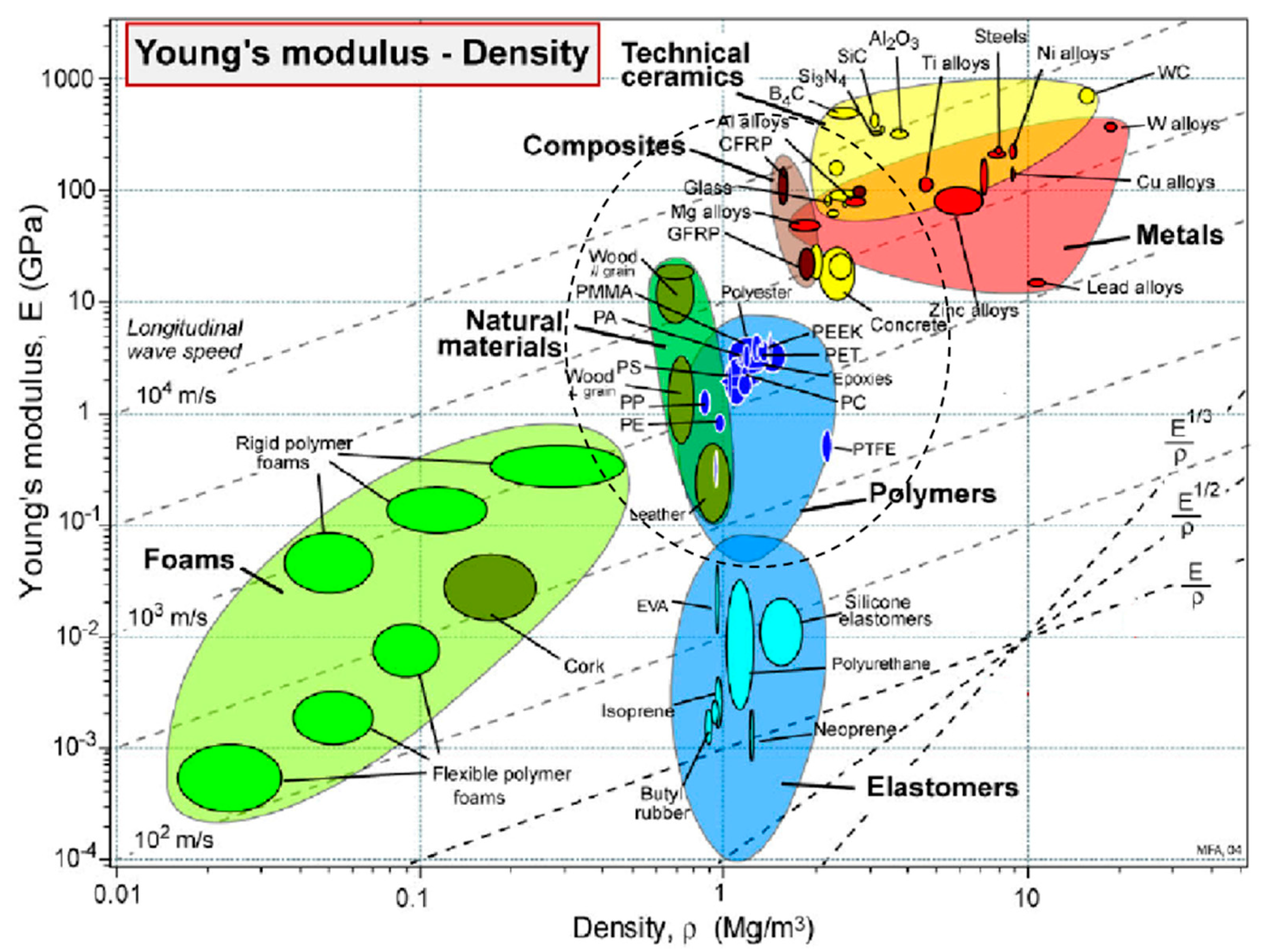
4. Materials for Wind Turbine Blades
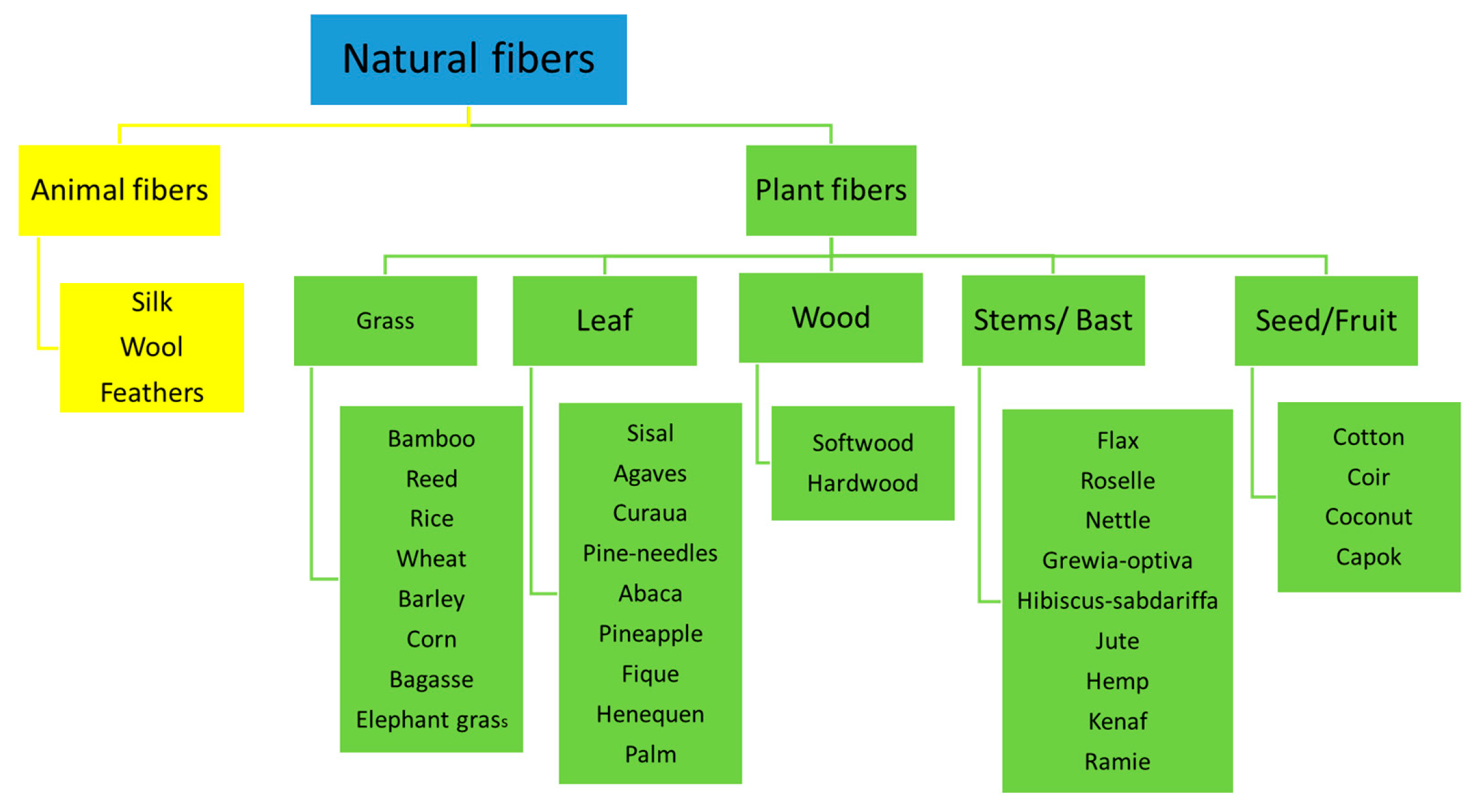
There are several materials for wind turbine blade construction, as shown in Figure 3, but the usefulness of these materials is dependent on their weight and rigidity. From Figure 3, it is observed that composites have good strength and good stiffness fibers. Despite the high strength and stiffness, composites are low in weight. The orientation of the fiber in the laminate determines the characteristic behaviour of the composite material [15].

4.1. Natural Fiber

The quest to decrease the price of materials for turbine blades led to natural fibers being used as materials for wind turbines. They often come as nonabrasive materials that are usually biodegradable. Most of these natural fibers are environmentally friendly, even though they have high strength and mechanical characteristics. The types of natural fibers are shown in Figure 4. They are obtained from minerals, plants and animals. One investigation concluded that bamboo has good stiffness as well as strength, and, therefore, it is suitable for the manufacturing of wind turbine blades.
It is, therefore, the future of the wind energy industry due to its fast growth rate, easy accessibility and environmental friendliness [35,36]. Another group of researchers concluded that 30% of the laminate being made of bamboo enhances the mechanical characteristics. They further identified that bamboo-filled reinforced composite absorbs a lower amount of water compared to empty reinforced polymer [36]. The life cycle analysis for bamboo has also been investigated to determine its characteristics with that of glass fiber blades. The group concluded that using bamboo was the best option for wind turbine blades [37]. Mechanical characteristics of coir fiber composites have also been investigated [38]. It was observed that their mechanical characteristics were almost the same as wood but different compared to glass fibers. A flax fiber turbine blade has also been developed at the University of Nottingham. These fibers often have high strength [39]. Machining flax fiber has also been researched. Delamination of the material occurs, because the fiber is brittle, and this is a major demerit when used as a blade. Absorption of moisture is a challenge when these materials are utilized; hence, they are subjected to reinforcement fiber treatment. The wettability of the surface for the fiber improves, and this helps the movement of stresses from the fiber to the resin.

4.2. Carbon and Glass Fibers

The volume content and the fiber stiffness determine the composite stiffness. For most composites, the main reinforcement material is made up of E-glass fibers. The compressional strength, tensile strength and stiffness of the composite material increases when the fiber volume content increases. Beyond 65%, some regions in the fiber dry up. This phenomenon lowers the fatigue strength of the composite material [32]. Epoxy composites used for wind turbine blades have 75% of their weight made of glass. Several research works aimed at enhancing fiber strength have been carried out. Well-known, high-strength fibers are basalt, carbon and glass fibers. They exhibit 40% high tensile and flexural strengths. The compressive strength of these materials is higher compared to E-glass by 10–20%. In terms of cost, the E-glass is cheaper compared to the S-glass. An S-glass was developed in 1968 for commercial purposes, and this was named the S2 glass fiber. The S2 glass has the same characteristics as the S-glass. The only disparity between the two is the coating of the fiber and processes for certification [40]. S2-glass is 10 times more expensive than the E-glass. Some other types of glass fibers are the R-glass fiber, Advantex and WindStrandTm [40,41]. An alternative to glass fibers is carbon fiber. The stiffness of carbon fibers is higher compared to glass fibers. They are also lighter than glass fibers. These properties make them suitable for wind turbine blades that are light, thin and stiff. A major setback for this material is that it can easily be damaged. It is also more expensive compared to the E-glass fiber [42]. The fatigue strength and compressive strength tend to reduce when there is a misalignment of the fiber in the carbon fiber composite. Companies such as Vestas and Siemens uses carbon fibers in some of their products.

4.3. Basalt Fibers

Aromatic polyamide fibers, also known as basalt fibers, have good mechanical strength and are generally tough. They are sometimes described as nonglass fibers. These materials feature low compressional strength as well as low adhesion to resins. They absorb water easily and degrade faster, as well [43]. The mechanical characteristics of E-glass are lower compared to basalt fibers. Basalt is 30% stronger than E-glass. It is 15–20% better than E-glass in terms of stiffness. The weight of basalt is lower than E-glass by 8–10%. Carbon fibers are more expensive compared to basalt. Using basalt as turbine blade material has also been researched [44,45].

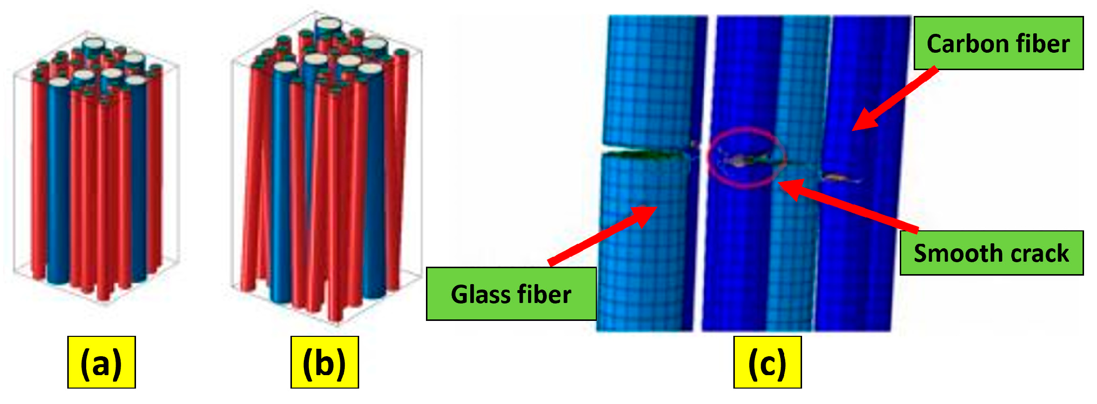
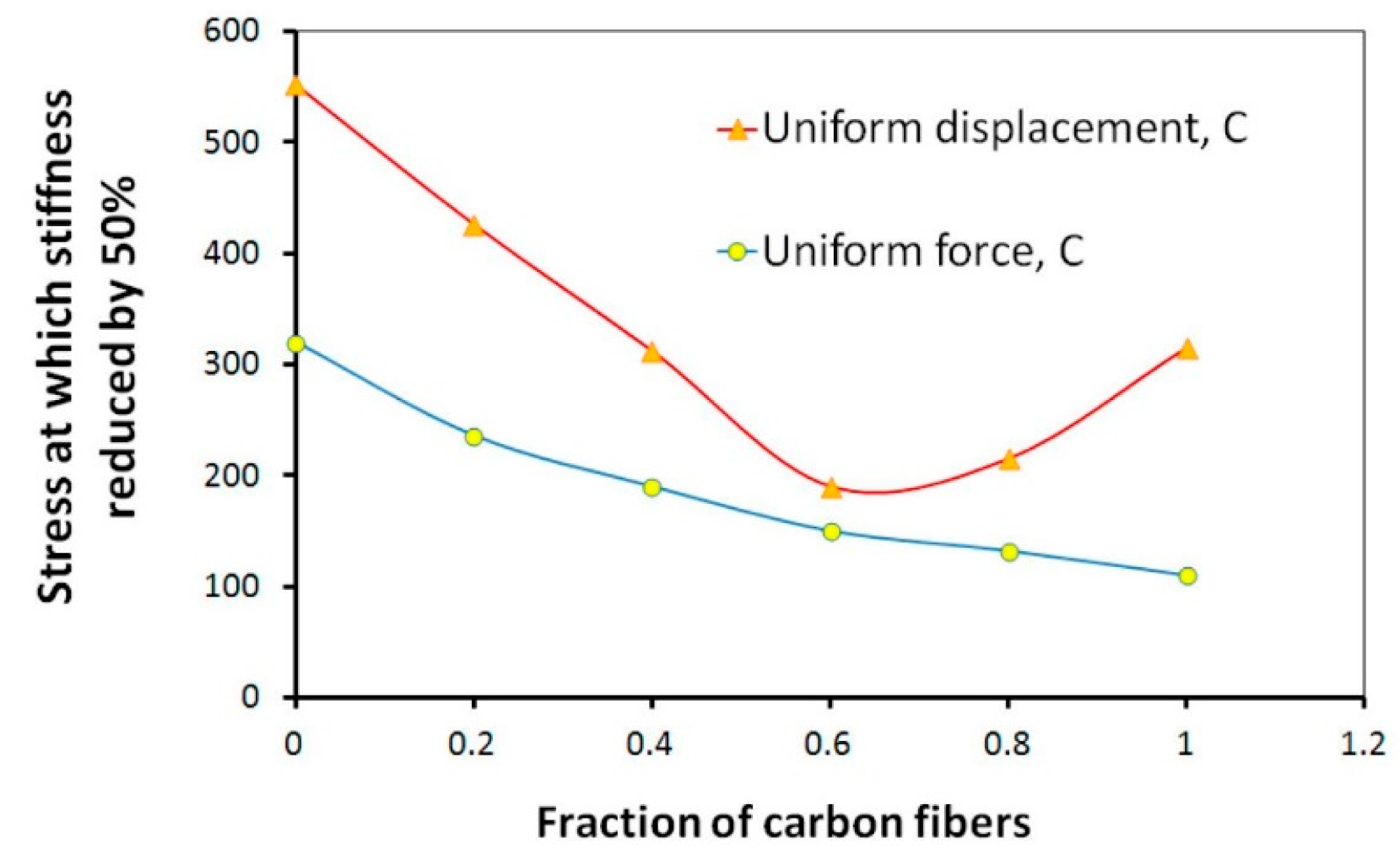
4.4. Hybrid Composite

Researchers today consider basalt as well as E-glass as an alternative to pure carbon reinforcement. Many investigations argued that full replacement may reduce the weight by 80% but will increase the overall material cost by 150%. There is a 90% increase in cost for partial replacement but a reduction in the weight of the turbine by 50%. The largest turbine blade developed in the world is 88.4 m in length and manufactured by LM Wind power; it is composed of carbon and glass hybrid composites [46]. The strength and failure mechanisms of these hybrid composite materials have been studied. Most of the investigations suggested that the strain-to-failure of the carbon fibers as well as the impact properties improved due to the addition of glass fibers in carbon fiber-reinforced composites. Another study also noticed that the combination of carbon fiber with ductile glass fiber in a hybrid composite improved the failure strain of the material. Using numerical analysis, it was observed that the composite strength as a function of the glass/carbon ratio was v-shaped. Experiments have also been conducted using the probabilistic fiber bundle model and micromechanical multifiber model [47]. Figure 5a,b captures a hybrid composite with the fiber misaligned and aligned. The cracking in the fiber is captured in Figure 5c.
The critical stress against the carbon fibers in hybrid composite is captured in Figure 6. It is further observed that mixing the fibers reduces the strength of the composite from Figure 6.

4.5. Matrix

Epoxy, vinyl esters, polyesters and thermoplastics are often preferred as wind turbine blade matrices for composite materials.

4.5.1. Thermosets

More than 80% of reinforced composites for wind turbine blades are manufactured from thermoset plastics. These materials can be cured at lower temperatures and even at environmental conditions. Most wind turbine blades developed in the past were made of polyester resins [49]. As the demand for energy increased, the need for urgent sources of energy also increased, and did that for blades of the turbines used in harnessing energy from these sources. According to some researchers, DSM composite resins have a quick cycle time. This material is also strong and durable, thus making it very suitable for manufacturing bigger blades [43,50]. Developing matrix material that has a faster pace of curing but at lower temperature conditions is an important area that requires further investigations.

4.5.2. Thermoplastics

These materials are considered a good replacement for thermosetting matrices [51]. They can be recycled, which is very advantageous. A major setback for thermoplastics is that they require high processing temperature [52]. Producing large as well as thick parts also becomes a challenge due to their high viscosity. The melt viscosity of thermoplastics is of the order 102–103 Pa s. The temperature for decomposition of thermoplastics is higher than their melting temperatures; hence, it is possible for them to be reshaped. Thermosetting has good fatigue behaviour compared to thermoplastics, even for carbon or glass fibers [53,54]. Thermoplastics have large elongation when fractured and can also be processed automatically. The shelf life of thermoplastics’ raw materials is unlimited.

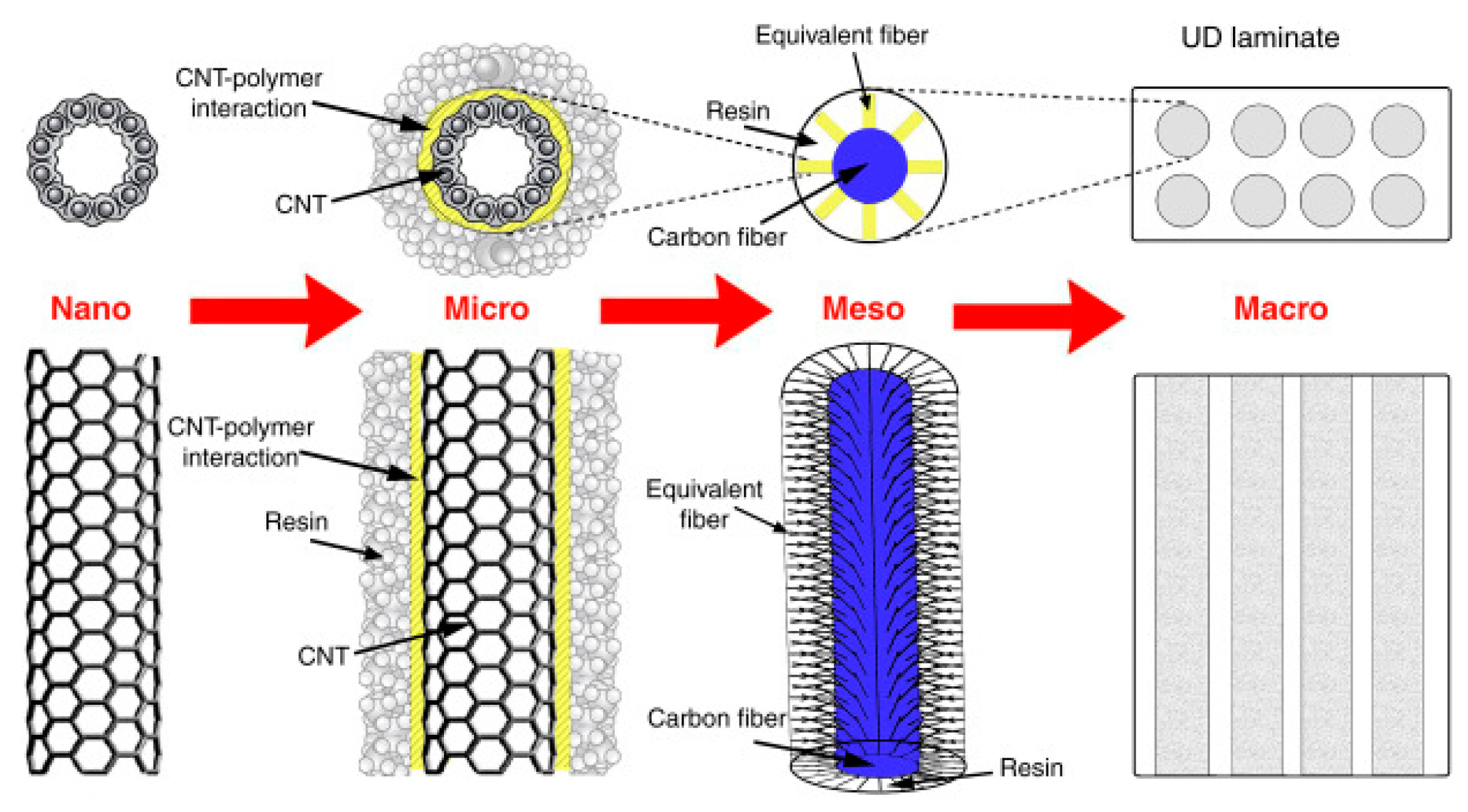
4.5.3. Nano-Engineered Composites

A number of investigations have been done to increase the characteristics of composites through the addition of nanotubes reinforcement in their matrix. To increase the fatigue resistance, shear or compressive strength, and the toughness by 30–80%, researchers suggest the addition of 0.5 weight percentage of nanotubes reinforcement in the matrix of composite material [55,56]. Vinyl ester, epoxy composites and thermoplastics have been used from literature in the manufacturing of wind turbines. The investigation showed that the addition of small carbon nanotubes increased the lifetime to more than 1000 percent [57]. Using graphene as reinforcement for the nanomodification of wind turbine composites has also been researched. The conclusion of the experimental investigation was that graphene is suitable for developing strong wind turbine blades and increases the life span of the turbine blade [58]. The tensile stress of wind turbine blades for 2 MW as well as 5 MW wind turbine increased when 1–5 weight percentage of carbon nanofibers were fused with glass fiber-reinforced epoxy composite. The weight of the blade is also reduced by 20%, and this increases the life span of the turbine blades [59,60]. Transfer of material characteristics of a specific polymer nanocomposite as a matrix to laminate with reinforcing fibers still remains a challenge [61]. The utilization of nano modified polymers as a matrix in order to enhance toughness often results in low property characteristics in other areas, and this reduces the application of nano modified polymers. Using nano-reinforced composites to replace glass fiber composite has also been researched [62]. An investigation also concluded that using non-reinforced composite as well as hybrids increased the lifespan of the turbine blade [62]. There is still work to be done in reducing the cost of wind turbine blades made of these materials. Figure 7 shows an image of carbon fiber with carbon nanotube reinforcement.
Ye et al. [64] conducted an investigation on the evolution of failure on composite wind turbine blades. The group of researchers developed a model for the determination of damages on composite wind turbine blades when exposed to varying load conditions. It was deduced from the investigation as captured in Figure 8 that the deterioration of the turbine blades originates from the upper surface. An increase in the load results in the matrix becoming damaged compressively, and this is noticed on the leading edge. The damage of the fiber also begins from the root of the blade.

4.6. Factors That Influence Damage of Fiber-Reinforced Composites

As explained earlier, a vivid comprehension of issues that causes the initiation of composite turbine blade deterioration is crucial in the life span of the blade. This is very critical, as the blades are likely to be subjected to varying loading conditions. There have been several investigations on issues leading to a deterioration of composite materials. Figure 9 captures salient information on varying deterioration mechanisms as a result of loading action.
The complications of damage mechanisms for composite materials are higher compared to others, because the material characteristics are constant in all directions. Again, when they are subject to loading conditions that are transient, the stresses generated are not distributed equally on the material [66]. This challenge is not an issue when dealing with metals, because they are ductile in nature and do not lose their toughness, even under deformation. Composites, on the other hand, are brittle; hence, they are likely to get damaged when subjected to any varying loading action. When composites are subjected to varying loading conditions, the matrix are often likely to crack due to shearing action. There is also the possibility of bending cracks, because the bottom part of the composite material is subjected to flexural stresses. Delamination is also likely to occur, because the cracks are restricted. There is also damage to the fiber due to tension, as well as buckling, when subjected to compressive action. The two common dominant damage modes at lower energy impact situations are resin cracking and matrix interfacial deterioration [67]. Breaking down of fibers is also another common failure mechanism caused during higher energy impact situations [68,69,70]. The resin system’s fracture toughness has also influenced the impact on composites. Resistance to fracture is lower for resin systems that are brittle. The opposition to the development of fracture is curbed when the matrix fracture toughness is improved. It, therefore, results in delamination due to resin cracking. Again, a mismatch within the layers for varying types of fibers as well as orientation can lead to intrepidly failure. There is an increment in the shear stress due to crack propagation in the layers. These phenomena occur dependent on the characteristics of the material. These cracks can further develop on the material interface, resulting in delamination [71]. The impact response for composite laminates is due to models I and II [72]. It must be noted that delamination occurs due to the opening of cracks in a model I, and propagation of cracks occurs because of bending [73]. Composite materials are capable of sustaining varying loads as well as releasing these stored energies under varying failure modes [74]. The impact energy subject to composite materials is sustained as a result of the elastic characteristics of the structure. The toughness of fibers of composites, as well as the interface, determines the elasticity of the material, and this determines the capacity of the impact energy being absorbed [75,76]. Many research activities have been conducted to determine impact damage from the literature [76]. The fiber’s chemical and mechanical properties have an effect on the rate of deformation of the composite. Other factors such as environmental conditions equally have a direct effect on the impact response. An understanding of different damage, as well as the progression the material will be subjected to at varying loading actions, is crucial to the lifespan of the composite material. Factors that affect impact response are summarised in Figure 10.
The dynamic characteristics of composite materials as well as their ability to oppose damages is important, especially during optimization of the material. There are waves produced elastically across the region where the load acts on the material. This results in deterioration of the material; hence, the timing at which the material is constantly subjected to the impact load causes the variation in responses [77]. For elastic waves where contact time stays within transition time, the characteristics are measured based on a transverse wave, as captured in Figure 11a. Prolonging the time kicks in the flexural and shear waves, as shown in Figure 11b.
When the duration for the impact exceeds that of the elastic wave at the target edges, quasi static characteristics are most likely to occur. This is represented in Figure 11c. The entire component undergoes deformation on impact, as captured in Figure 12a. The region closer to the point of impact is the area where the deformation is most likely to be predominant, as shown in Figure 12b.
When the speed of the impact is less than 11 m/s, it is considered low-velocity impact; this is common in the event of maintenance activities. Bird strike on the blade is considered a high-impact event, as the impact normally exceeds 11 m/s. The ballistic impact is also carried out for applications ideal for the military, and this type of impact occurs beyond 500 m/s. When the impact velocity is more than 2000 m/s, it is considered hypervelocity impact. These impacts can further be subclassified into lower-velocity impacts and higher-velocity impacts. Kinetic energy is sustained properly in low-velocity impact, unlike the high-velocity impact.

5. Failure Modes of Wind Turbine

Wind turbine blade and tower failures have become less common with the passing of time. It is the result of continuing attempts to resolve and correct the popular failure factors, which has resulted in more efficient wind turbine blade production. However, as the number of wind turbine installations in the industrial sector grows, new issues and difficulties arise. Some of these failures are attributed to the turbines ageing and exceeding established fatigue life limitations; others are because of material faults and manufacturing flaws, coupled with modern failure modes attributable to improved rotor size. As the number of turbines onshore or offshore grows, so will the number of accident cases [80]. Figure 13 shows the amount of wind turbine damages that happened worldwide from 2000 to 2017 [81]. These figures clearly show that, while there were fewer wind turbines in operation, there were fewer incidents, with the number of accidents rising in tandem with the increasing number of wind turbine set-ups. From 2000–2005, there were 57 incidents per year on average, which increased to 118 cases/year from 2006–2010. Total number of damage cases each year between 2013 and 2017 was about 167.
On a global scale, Figure 14 depicts the amount of blade and structural defects. The statistic shows the rate of structural malfunctions is significantly lower in comparison to number of blade malfunctions. In 2013, the highest total wind turbine blade breakdowns ensued, although the lowest number of structural failures (16) occurred in 2009. To minimise failures, further technical advancement is needed in areas of wind–blade interaction, blade processing processes and the production of novel materials [82,83,84,85].
As blades malfunction, the rotor can be removed from the blades entirely or in fragments. Depending on the rotor size and rpm, a piece of blade will fly up to 1.6 km due to centrifugal and Coriolis forces. In a recent incident in Germany, several blade scraps pierced the roofs and walls of surrounding homes, indicating that wind turbines must be built 2 km away from domestic buildings. Figure 14 depicts several unusual wind turbine tower and blade malfunction scenarios [81,85].
With the aid of a compact scale prototype wind turbine that can operate upwind or downwind, Kress et al. [86] calculated and contrasted yaw stability of three separate downwind rotors with subsequent upwind rotors in an experimental analysis. The investigation revealed that downwind rotor designs have yaw endurance at near full-scale Reynolds quantities, while upwind turbines are either unpredictable or have dramatically decreased yaw constancy. The shaft strength and rotor thrust were higher in downwind configurations with a 0°, 5° and 10° cone than in upwind designs. Downwind configurations, on the other hand, provided 5% more power and just 3% more thrust than upwind configurations at zero yaw and 5° and 10° cone angles. Subject to field and wind tunnel results, aero–servo–elastic measurements, as well as engineering judgement, Abdallah et al. [87] suggested realistic stochastic model to measure instability in airfoil drag coefficient as well as static lift. The findings revealed that, subject to the part and operational parameters, coupled with correlations of aerodynamic variables along blades’ width, instability in static airfoil data has a major effect on the estimation of severe loads impact as well as structural dependability. Based on three main configurations and malfunction statistics review details of wind turbines in China, Lin et al. [88] summarised malfunctions of wind turbine parts such as blades, etc. Failures were discovered to have four key causes, according to the study: (i) a shortage of key technology, (ii) lower quality of materials used due to market competitiveness, (iii) construction requirements and disparities in wind farm climates and (vi) no required quality certification as well as external influences.
Highest breakdown rates of wind turbine parts [89] were observed at mean wind speeds of 12–14 m/s (Figure 15).
For four towns, Sathe et al. [91] simulated wind turbine loads for the NREL 5 MW reference wind turbine. The analysis found that atmospheric equilibrium has an effect on the tower as well as rotor loads but that it has no impact on the blade loads. Moreover, loads caused by wind profile were greater under stable conditions because of enhanced wind shear, while loads caused by turbulence were smaller because of less turbulent capacity. Wind turbines may be constructed in seismically active areas, as global wind power development indicates, and entire clusters of equally built installations could be at risk of collapsing at the same time in the case of a major earthquake [92,93]. Only a few published research seem to have taken into account the time domain nonlinear dynamic reaction of a wind turbine support tower [94,95]. Nuta et al. [92] used a suite of earthquake data reflecting North American seismic activity in areas such as Los Angeles and Western Canada to investigate an 80 m tall 1.65 MW wind turbine steel tower with diameter-to-thickness (d/t) ratios varying from 105 to 278. Stamatopoulos [95] used nonlinear springs to model a reaction continuum as well as a single time–history study on a 54 m tall “perfect” hollow steel tower with d/t ratios varying from 51 to 134. As opposed to a reaction continuum analysis, the time–history analysis expected almost 50% higher values of the base shear and overturning moment.
Nebenführ and Davidson [96] utilized large eddy models to model the neutral atmospheric boundary layer over a fragmented and thick woodland, as well as a flat grassland. The effects of forest density, wind direction and wind turbine hub height on wind turbine fatigue loads were investigated, and it was discovered that the equivalent fatigue loads increased substantially between the two forests (sparse and dense). Sadowski et al. [97] published a detailed study of the seismic reaction of a 1.5 MW wind turbine supported by a steel tower modelled as a near cylindrical shell framework with functional axisymmetric weld depression imperfections in a near-cylindrical shell structure. A sample of 20 earthquake ground movements, 10 “near fault” and 10 “far fault” was seen as a flaw. Under seismic excitations, the tower developed a particularly brittle plastic hinge, which resulted in high stiffness. Near fault earthquakes with pulse-like effects and high vertical accelerations were found to be considerably more destructive than far fault earthquakes without these features.
Chou et al. [98] studied the reasons of wind turbine blade failure, especially delamination and splitting of the blades, in a wind turbine blade failure study. They also conducted a critical review of the literature in order to determine the most frequent causes of turbine blade failures. The harm mechanisms were then established by analysing the structural dynamics of blades using behavioural models. The empirical findings are intended to aid in the potential reduction/prevention of related engineering accidents. Extreme winds placed wind turbines’ structural stability in jeopardy. Chen and Xu [99] used postmortem research to investigate the systemic collapse of wind turbines caused by harsh wind conditions such as Super Typhoon Usagi in 2013. (PMA). The research focused on the impact of high wind speeds and rapidly shifting wind directions on tower collapse and blade fracturing.
The investigation recommended that the existing IEC architecture specification be modified, as well as a few possible future guidelines for reducing the possibility of wind turbine failures in severe wind environments such as typhoons and hurricanes. The postmortem review has become a popular method in software engineering for determining and analysing elements of a finished project to decide if they are functional or not [100]. This method entails determining the underlying factors of challenges and progress that occurred during the project, as well as suggesting process changes that will aid in reducing potential project risks [101,102]. The PMA was utilized to investigate defects of polyvinylidene fluoride pipes [103], power transformers with temperature transfer on surfaces [104], refractory linings [105] and compression of cast Al–Si alloys [106].
Ishihara et al. [107] examined failure of two turbine towers in Japan in 2003 triggered by Typhoon Maemi. They discovered that the toppled towers’ overall bending moment was greater. Chou and Tu [108] and Chou et al. [98] looked into reasons for a wind turbine’s tower failure and rotor blade destruction during Typhoon Jangmi in Taiwan in 2008. The fall of the tower during high winds was caused by inadequate power and low-quality bolts, according to the report. Poor blade material resistance, wind frequency and resonance impact and human errors during turbine installation, on the other hand, have been reported as primary causes of wind turbine blade destruction. Zhang et al. [109] performed a set of tests to determine the chemical composition and mechanical properties of shafts in order to determine the cause of shaft failure. As contrasted to the EN10083-3:2006 standard, the findings revealed no major variations in the material and mechanical properties of the main shaft. The main shaft fracture was caused by stress accumulation on the shaft surface combined with high-stress concentration caused by a difference in the inner diameter of the main shaft, according to the report. Furthermore, the experimental stresses at the shaft’s end showed that cracks would easily form under the influence of impact loads. Jensen et al. [110] investigated a 34 m wind turbine blade and its load-carrying spar girder to failure and discovered that the Brazier impact caused large deformation in the spar cap, which contributed to more delamination buckling and blade collapse. Overgarrd et al. [111] measured a 25 m blade to failure and found that instability phenomena such as delamination and buckling impact were responsible for the blade’s ultimate power. Yang et al. [112] investigated the structural failure of a 40 m blade and discovered that the key cause of blade collapse was debonding of aerodynamic shells from adhesive joints. Chou et al. [108] studied a typhoon-damaged composite blade with a blade length of close to 39.5 m and found that the blade collapsed through delamination and cracking at a wind speed of 53.4 m/s, despite being designed to withstand forces at 80 m/s. Chen et al. [113] presented the preliminary results of a failure study of a massive composite blade (52.3 m). Static loads were added to mimic the blade’s intense load conditions. After the blade failed, it was discovered that it had several failure modes. The disastrous loss of the blade was discovered to be caused by delamination of unidirectional laminates in the spar cap.
Damages found in several blades of 300 kW wind turbines were found to be caused by a fatigue process, according to an examination [114]. The failure triggers (such as superficial fractures, geometric concentrators and sudden changes in thickness) were investigated and confirmed using a generalised fatigue life assessment protocol based on the “Germanischer Lloyd” (GL) norm. Lacalle et al. [115] investigated the source of cracking in a wind turbine tower. The welded joint between the lower ring of the towers and the flange linking the towers to their respective foundations was found to have cracks. Nondestructive experiments on the base steel, the weld bead and the heat-affected zone (HAZ) were also performed. A finite elements (FE) simulation was used to assess the stress condition in the welded joints as well as the fatigue analysis in conjunction with the fatigue module of the FITNET FFS Procedure. The findings revealed that the key cause of the cracking mechanism was a poor joint configuration with elevated stress concentrations as well as a flange with insufficient resistance. Karthikeyan et al. [116] presented a comprehensive analysis of different blade profiles as well as airfoil geometry optimization processes for small wind turbines with Reynolds numbers less than 500,000. Chehouri et al. [117] issued a report of wind turbine efficiency enhancement techniques and solutions using objective functions, architecture limits, methods and models and as optimization algorithms. Yang et al. [118] used a succinct literature study to present a systematic analysis of nondestructive testing (NDT) methods for wind turbine blade (WTB) inspection. The study covered common flaws and harm in WTB manufacture and operation, as well as advances in visual, sonic and ultrasonic, optical, electromagnetic, thermal and radiographic nondestructive testing (NDT) for composite WTB, as well as the strengths and shortcomings of NDT techniques.

5.1. Extension of Wind Turbine Blades

The energy efficiency rises as the rotor diameter grows. Widening the height of the wind turbine blades is a practical approach to increase the energy production of current wind turbines [119]. The blade extension can be achieved using adhesively bonded technologies [120] or metal bolt attachment [121]. As opposed to metal bolt connections, the adhesively bonded technology of stretching blade size is smoother, has greater fatigue characteristics and adds less burden to the rotor. Adhesively bonding technology is a suitable method for expanding the service life of wind turbine blades, thus increasing energy efficiency [122]. Erratic aerodynamic loads caused by stochastic turbulent incursion, on the other hand, may cause fatigue as well as failure. An analysis of the strain reaction and fatigue for adhesively fixed extended composite wind turbine blades subjected to erratic aerodynamic loads was discussed in the article. The research reinforced the blades’ extendibility using adhesively bonded technology, resulting in a lower chance of adhesively bonded structures [122]. A thorough study of rotor abnormalities was carried out almost two decades ago, with the most frequent being aerodynamic asymmetry and yaw misalignment being identified as the most common [123]. Even before then, a study on the behaviour of bearings caused by nonuniform airgap and slip-speed was carried out [124]. In one study, the torsional oscillation and the variation of the torque/speed ratio of a synchronous Wind Turbine (WT) generator were investigated in order to diagnose drivetrain faults [125]. Other rotor fault detection possibilities are discussed in their research, a possibility that has previously been investigated in [126], where, for example, the mass imbalance was discovered, and the implications of this imbalance were taken into consideration. The blade integrity of wind turbines is a critical element in determining their operating characteristics. In addition to creep and corrosion fatigue [127], which may have catastrophic effects owing to improper maintenance and inspection of cracks, delamination of the composite blades due to fatigue [128,129] is also an important failure mode for rotors. Ice, filth and moisture build-up may cause rotor imbalance [130] and aerodynamic asymmetry, which are both dangerous. It is also possible that wear build-up on the rotor blades is the underlying cause of these problems. Aside from hubs spinning on the shaft [131], other frequent rotor failures include shaft misalignment [128] and hubs spinning on the rotor [132]. When the blade surface roughness of a WT increases, it may result in a reduction in the amount of energy collected (also known as efficiency loss). This phenomenon and surface wear [133] are caused by erosion, ice and other factors to which the wind turbine is exposed over time. Pitch control system may also help to prevent or minimise flap-wise fatigue damage to the blades [134], which is a kind of failure that can occur. Unfortunately, various kinds of faults and damage occur in wind turbine blades, and not all of them can be detected via monitoring. Lightning strikes, which are, in theory, an unintentional spontaneous occurrence, may cause damage to turbine blades. Lightning protection systems [135] are used to prevent damage; nevertheless, they do not provide full protection from lightning strikes. There are a number of other frequent blade defects or direct repercussions of these flaws, including: excessive vibrations [136], unstable performance [135], corrosion [137] and unsteady blade air loads [137], all of which may result in blade breakage [127], in the worst case scenario.

Pitch Control System

Pitch control system is designed for energy collection, operational load reduction, wind stalling and aerodynamic braking [138], making it an essential component of the wind turbine operation. Pitching failure is very essential to prevent since this failure may have devastating effects if not avoided. When high winds endanger the turbine’s ability to operate safely, aerodynamic braking is employed to bring it to a halt. In most cases, a hydraulic actuator or an electric motor is in charge of controlling this subsystem. Even while electric motors provide faster reaction times, they have poorer stiffness and dependability when compared to hydraulic systems, and as a result, they are regarded less fail-safe [128]. Certain hydraulic system defects [139] result in operational instability; nevertheless, early brake activation [127] undermines the desired operating mode of the system. Other instances of pitch control system failures include: a reduction in effective bulk modulus of hydraulic fluid caused by air pollution of the hydraulic system, a decrease in the plant’s bandwidth and a large leakage in the hydraulic system [140]. All of these failures result in a decrease in the stability and resilience of the associated closed-loop system. When there is an asymmetry in pitch angle [128], the wind turbine shuts down.

5.2. Gear Box Failures

The efficiency of wind turbines has increased in recent years as production technology has advanced, but gearbox issues still remain. According to figures [141], the primary breakdown components of a wind turbine in the last ten years have been the gearbox, engine, low-speed shaft, high-speed shaft, rotor, yaw mechanism, pitch and control mechanisms. As contrasted to the damages associated with other wind turbine crashes, gearbox failure usually results in the longest downtime and highest economic loss [142]. The planetary gear loss mechanism is categorised into two stages: fretting wear and fatigue source production. The stiffness disparity between the inner surfaces of the gear and the outer ring of the bearing, the influence of fit resistance on fretting slip distance and the impact of gear hub thickness on fretting slip distance are both measured during the fretting wear stage checking. The above interventions were shown to be very successful based on the experimental results and relevant research [142].
From all the other parts of the wind turbine drivetrain, the gearbox has been shown to be the component that experiences the greatest number of failures [128,143]. According to the findings of a relevant study [144], gear tooth damage and bearing failure are the most common types of failures. According to the same study, “among all bearings in a planetary gearbox, the planet bearings, intermediate shaft-locating bearings, and high-speed locating bearings tend to fail at a higher rate, whereas the planet carrier bearings, hollow shaft bearings, and non-locating bearings are the bearings that are most likely to fail.” An additional significant failure is decoupling between the shaft and the gearbox, which is considered to be catastrophic [127], whereas other faults such as pitting, cracking, scratching and other faults are graded with lower cruciality [144], as they can be spotted on time via gearbox diagnosis and condition monitoring (CM) techniques, e.g., acoustic emission (AE) [145] or auto-associative kernel regression (AAKR) [146]. Captured in [136] is data relating to wind turbine drivetrain diagnostics, in which electrical evaluation was used to check for mechanical flaws, and the diagnosis of gear eccentricity was examined, both of which were successful. An essential element of the wind turbine rotating parts, and especially of the gearbox [147], is the provision of effective lubrication [148,149,150]. Various variations in oil characteristics, such as viscosity, water content, particle count and debris, are often utilised as indicators of possible defects [150] and are frequently used as inspection techniques.

5.3. Generator

The wind turbine generators are one of the subsystems that have a high rate of failure. The stator, rotor and bearings are the most often affected by these problems. According to [132], bearing malfunctions account for ~40% of induction machine malfunctions, whereas 38% of stator failures and 10% of rotor failures are attributed to bearings. For example, failures at the winding circuits of the stator or rotor can include opening or shorting interturn failures, abnormal connections at winding circuits of the stator, dynamic eccentricity, broken rotor bars, cracked end rings, static and dynamic airgap eccentricities, among other things. It is also possible that the consequences of those failures will be measured as possible faults, e.g., imbalances coupled with harmonics in the air gap flux, as well as phase currents, an improvement in torque pulses, a reduction in average torque, complex losses, a loss of performance and winding overheating, among others. Using two methods, the fast Fourier transform (FFT) and Wavelet analysis, a power signal was used to identify rotor instability coupled with bearing problems in a rotor. An electrical problem that may occur in these systems is a shorted winding coil, which lowers the synchronous reactance of the generator. This is one of the most common electrical faults that can occur. It has been classified as critical, and remedial action must be taken as soon as possible once it is discovered in the environment. When a shorted coil is generated, it has been shown in [136] that a greater mechanical force is required to achieve an equivalent shaft rotational speed. Furthermore, shorted winding coil failure often manifests itself considerably more quickly, in the range of minutes, as opposed to the days or months that it takes for a mechanical deterioration malfunction to manifest itself. Different kinds of rotor faults may be classified as follows: rotor eccentricity, breaking of rotor cage bars and breakage of end-rings. These malfunctions are liable for the generation of certain secondary flaws that may result in severe malfunctions, such as winding coupled with excitation imbalances or interturn short circuits, among other things. Rotor eccentricity occurs when a nonsymmetric airgap is created between the stator and the rotor as a result of the rotor being shifted off of its original location in the centre of the stator bore [151]. According to [27], the maximum allowable amount of eccentricity is between 5 percent to 10 percent of the airgap length. In any case, it is critical that it be recognised quickly, because, when the stator rubs the rotor or vice versa, catastrophic effects may ensue due to motor’s windings, stator core and rotor cage [148,151]. When the stator rubs the rotor, the motor is gradually destroyed. Squirrel-cage induction machines (SCIM) are susceptible to rotor bar cracking, as described in [152], which may occur as a result of loads and/or poor rotor geometry design during operation. Bar breakage is the most severe failure mode for the SCIM rotor because, when it occurs, the degradation of neighbouring bars begins as a consequence of the increased redistributed loads. Bar breakage is also the most expensive failure mode [153].

5.4. Power Electronics and Electric Controls

Electronic mechanisms account for 13 percent of all wind turbine breakdowns, while wind turbine commissioning expenses account for 1 percent of all WT failures [128]. In order to improve electronic failure, it is critical to improve its diagnostic methods. Another essential point to remember about variable speed and direct drive WT is that power electronics is responsible for a considerably larger fraction of the entire price of ownership than for constant speed WT [127]. According to certain research, the majority of power electronic system breakdowns are due to semiconductor failures in power electronics circuits. As a result, several questionnaires were developed for the purpose of investigating these device failures [154], with the emphasis on the main faults of three-phase power converters including open circuit, short circuit and gate-drive circuit faults. According to the outcome of the survey, “due to the temporal criticality of these defects, fault detection and diagnostic techniques for these semiconductor devices should be implemented as protection functions rather than monitoring functions”, rather than monitoring functions.

5.5. Towers and Foundation

The wind turbine tower and its foundation are both important parts since they are unable to be changed in the same manner that most other components can. Due to the fact that fatigue [155], cracks and corrosion are possible failure modes, the underlying causes of these must be addressed on a regular basis via inspection and monitoring [156]. A wind turbine is intended to have a 25-year operating life; however, some occurrences may pose greater risks compared to those predicted when designing the wind turbine. Earthquakes, unanticipated soil volatility and unwarranted tainting of the foundation, to name a few examples [157], are all potential consequences. In most cases, however, there are significant variations concerning the loads and ambient situations that wind turbines are created for and the actual circumstances encountered in practice. Malfunction activities, such as corrosion coupled with fatigue, may be significantly exacerbated by these variations, increasing the degree of danger. Consequently, frequent inspection as well as monitoring via structural health monitoring systems (SHMS) are highly suggested for both the tower and its foundation, particularly at the beginning of a scheme, to allow changes to be rectified as quickly as feasible. When it comes to OWT, foundations are critical, because if they fail, it would result in the collapse of the whole system.
The location must thus be subjected to a thorough geotechnical evaluation [158]. As previously stated in [159], cyclic capabilities in the foundation layout should be sufficient to support the edifice when exposed to external cyclic loads. Again, it must be able to keep the degree of distortion within acceptable limits during cyclic loading. Meanwhile, foundations must be capable of withstanding significant uncertainty not just in terms of soil environments but of soil characteristics, precision of computation techniques and loads estimate. Furthermore, owing to the criticality of this subsystem, as was the case with when designing the tower, discrepancies between design and actual circumstances must also be reduced and managed in the foundation design, as was the case with the tower design [160]. As a result, it is normal to assume that wind turbine foundations are covered by the same kind of guarantee that WTs are; however, this is not always the case, and in certain cases it is not. Foundation risks, on the other hand, are insurable and may be reduced via the use of certification. As a result, the maintenance of WT foundations should be executed in distinct manner, primarily via visual inspections coupled with survey work, with risk remedial labours being performed only when absolutely required. Structure strength, lifting, climbing and safety equipment, corrosion and scour protection are all assessed by these many kinds of inspections. Restoration of paint to foundations and subsea structures, removal of excess marine growth from foundations, rock placement to improve scour resistance and sporadic repairs are all part of the foundations and subsea structure maintenance.

5.6. Summary of Wind Turbine Blade Failure Modes

Variety of failure and harm modes can cause wind turbine blades to malfunction. Extent of damage evolution can vary depending on the blade profile. However, regardless of blade design, evidence has shown that a blade can produce a variety of material-related and structural-related harm modes. These harm modes may cause blade loss or necessitate blade repair or replacement in certain cases. A composite structure’s failure may be caused by a variety of factors:
  • Buckling, massive deflection, crushing and folding are all caused by geometrical influences.
  • Plasticity, ductile/brittle breakdown, rupture and splitting damage are also material considerations to consider.
  • Original fabrication flaws, such as initial distortion, residual stresses or manufacturing flaws.
  • Low temperatures are correlated with activity in cold climates, and high temperatures are associated with fire and fires.
  • Dynamic factors (strain rate sensitivity, inertia influence, damage) linked to impact pressure caused by explosions, dropped artefacts or related events.
  • Fatigue cracking is an example of age-related degradation.
To determine the manner in which destruction occurs in a wind turbine blade as well as to construct a blade against failure using analytical or computational techniques, a significant amount of expertise is needed. Blades are often measured to failure in full-scale trials to verify the specification and gain insight into potential harm modes and their seriousness. Figure 16 depicts the failure modes discovered in a wind turbine blade that was screened to failure [161]. According to a report by Jensen [162], there are many common types of faults and defects in wind turbine blades. Table 1 presents a summary of wind turbine blade failure modes

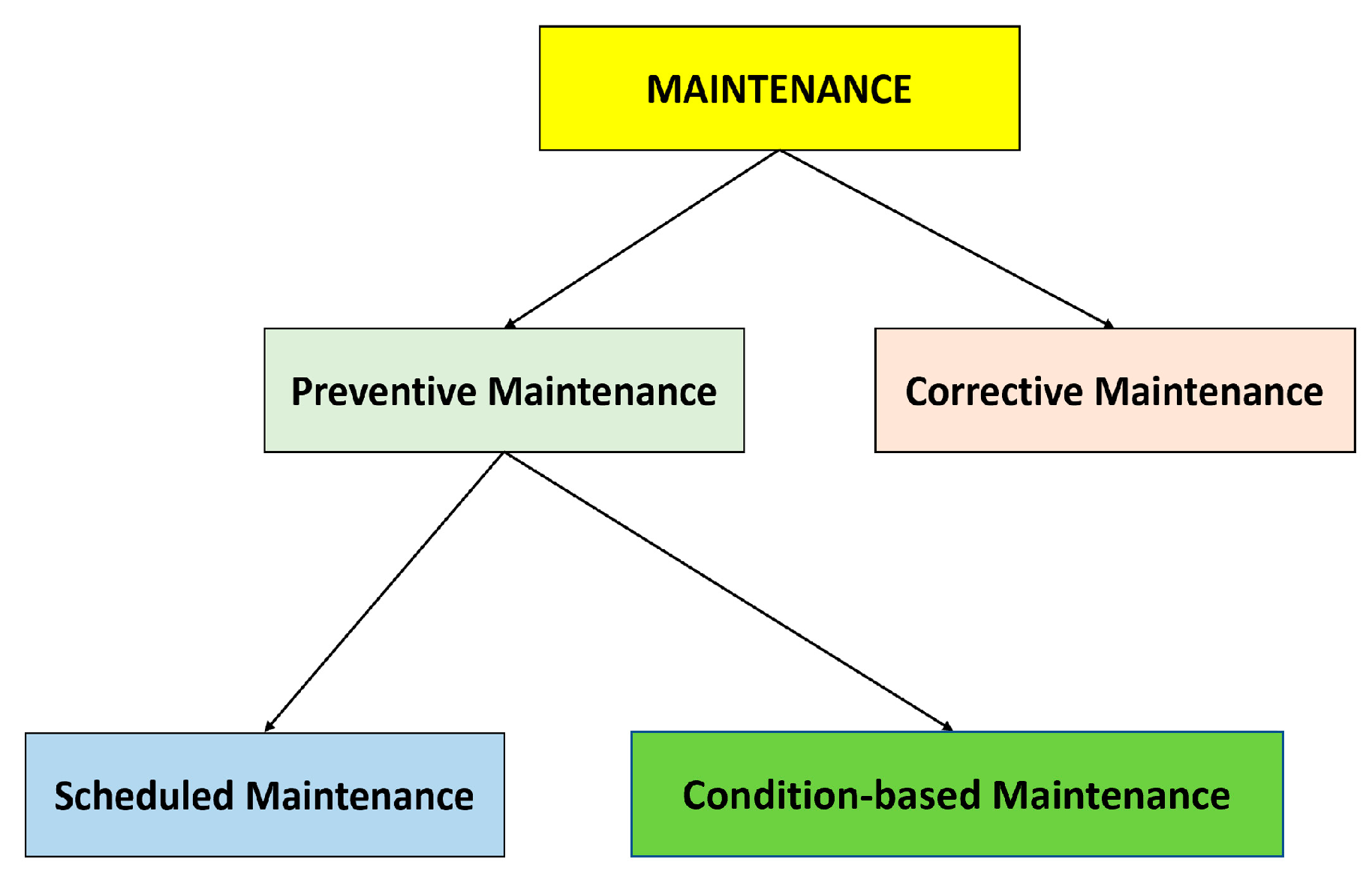
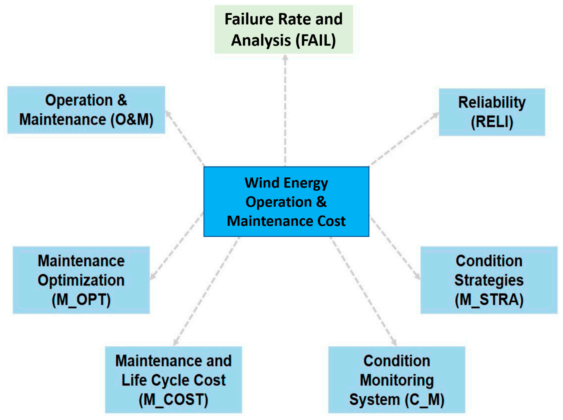
5.7. Maintenance for Wind Turbines

Wind turbines, like all other mechanical, electrical or mobile systems, need repair throughout the course of their lives. Mone et al. (2017) [164] calculated the price of operations and maintenance (O&M) for WT to be 14.6 $/MWh for a 2 MW onshore wind turbine in a 200 MW project and 49.6 $/MWh for a 4.14 MW offshore wind turbine in a 600 MW project. For onshore as well as offshore wind turbines, equivalent lifetime cost of operations and maintenance (O&M) are about $2 million and $14.8 million, respectively. Wind turbine repair is categorised into two: preventive and corrective. Planned service and condition-based maintenance are two types of preventive maintenance. Wind turbine producers prescribe 6-month intervals for scheduled repairs, and onshore wind turbines are normally maintained at 6-month intervals [165]. Condition-based maintenance necessitates an additional expenditure in a condition management device, but it avoids unexpectedly large malfunction costs as compared to planned maintenances. Corrective repair, on the other hand, is performed in the event of a defect that necessitates restoration or replacement. This categorization of wind turbine servicing is depicted in Figure 17 [166].
There are a variety of condition management procedures that can be utilised in both routine and condition monitoring-based maintenance. As seen in Table 2, Tchakoua et al. (2014) outlined potential malfunction mechanisms and associated testing procedures for wind turbine systems and modules. In terms of operation, destructive testing (DT) and nondestructive testing (NDT) for modules and subsystems of wind turbines are two forms of preventive maintenance. The following are the most popular DT methods for tracking wind turbine condition:
  • Oil Analysis (OA) is used to assess the consistency of oil within a wind turbine gearbox and whether debris contaminant is present due to harm to bearings and gearings [167].
  • In a wind turbine, electrical results are added to electrical devices such as turbines, pumps and accumulators [167].
  • The shock pulse system (SPM) is a technique for detecting bearing harm utilising transducers and signal reading [168].
  • The below are the major NDT for wind turbine modules and subsystems:
  • Ultrasonic monitoring techniques (UTTs), which are used to assess surface and subsurface structural deterioration on wind turbine towers and rotor blades [168].
  • Visual inspection (VI) is an ancient condition monitoring method that is used to detect problems that other condition monitoring techniques fail to detect, such as loose bits, contacts, oil leaks, rust and chattering gears [167].
  • Vibration analysis (VA) on WT parts such as shafts, bearings and rotor blades, as well as subsystems such as the gearbox [168]. Vibration sensors are applied to the surface of the inspected object, and data for the frequency of the component’s vibration is investigated.
  • Strain measurement (SM), which uses strain gauges to calculate stress levels in situ and predict lifetime in a laboratory [168]. It is primarily used on wind turbine blades.
  • To locate defects in gearboxes, bearings, shafts and blades, acoustic emission uses transducers and optic fiber displacement sensors [167].
  • Infrared cameras are used to identify hot spots in electrical and mechanical devices, as well as rotor blades, in thermography [168].
  • Using data such as strength, wind direction, rotor blade angle and rotor speed, performance analysis may be used as a wind turbine condition monitoring technique [168].
  • X-ray imaging is used to expose close delaminations or cracks in a wind turbine part during radiographic inspection [168].

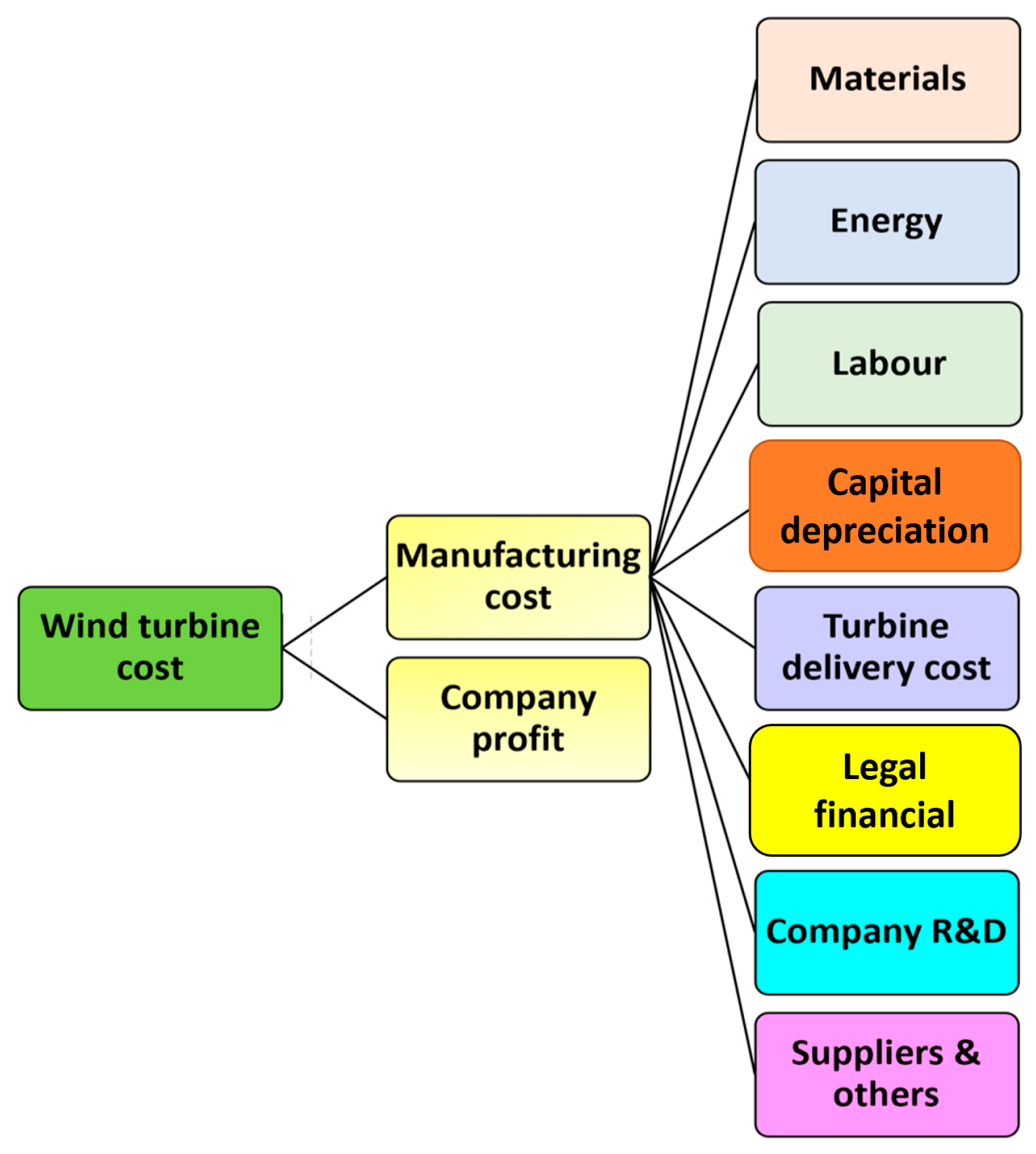
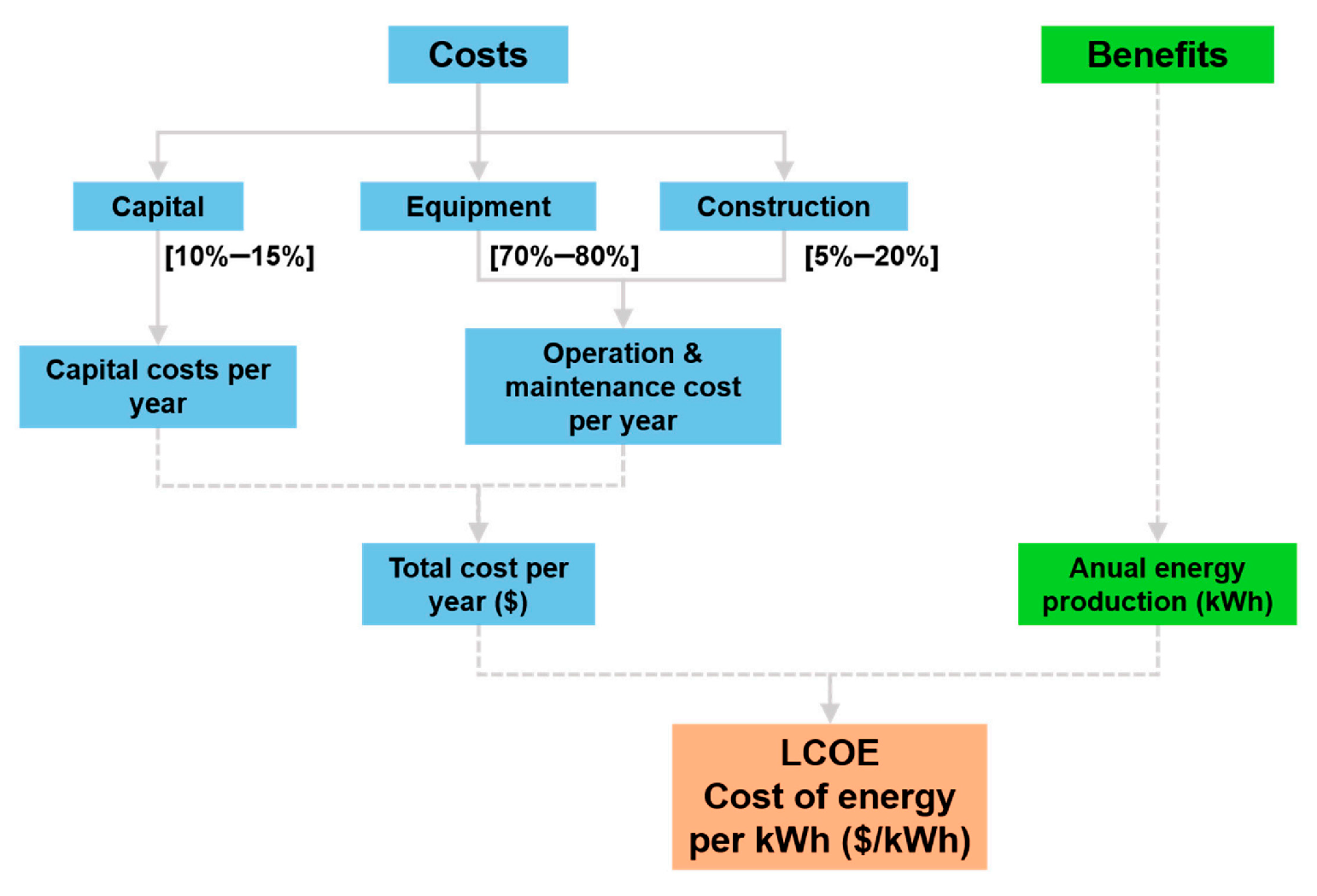
6. Overview on Cost of Wind Turbine

As highlighted in the analyses of improvement settings designed to guide national and foreign climate policy, the implementation of clean energy resources must be increased to reduce global warming [169,170,171]. Comprehending factors for green energy price savings is critical. By breaking down overall cost savings through their component parts as well as drivers, we will see which policy areas have the most cost-cutting ability. Onshore wind energy was utilised as a real-life scenario to describe factors for technological cost savings in present scenarios where prices have dropped significantly due to increased global penetration and tailored policy structures. Onshore wind is now an established technology with a growing international and local supply chain, with rising market growth [172]. Wind energy installed power crossed 540 GW at the end of 2018, accounting for 5% of overall global electricity generation. The year 2018 saw the levelized cost of electricity (LCOE) of onshore wind energy in Germany reduced compared to traditional fossil fuel technology [173]. Governments use the LCOE to screen and review policy choices, since it is commonly used to assess and compare renewable energy sources [174]. Costs of wind turbine (Figure 18) have direct effect on the overall price [175]. Emphasis on identifying the fundamental drivers of technology cost savings is not unique to the literature, where qualitative debates have attempted to clarify cause for observable cost reductions at various stages of technology growth. Using the principle of drivers, various macro dynamics affecting advancement of a technology and their prices, such as industrial learning, economies of scale and learning by engagement, coupled with influence of R&D growth, have been established [176]. Researchers have often attempted to measure the effects of these factors. The one-factor learning curve (1FLC), which depicts the relationship between costs and installed capability, is the most widely utilised method [177]. Only one driver of cost shifts, deployment-induced learning, can be captured by 1FLCs. This high-level aggregation obscures fundamental drivers, which may behave another way [178].
A group of researchers has established and implemented more sophisticated strategies such as multifactor learning curves (MFLC) that may include several criteria to model technology cost decrease if data is usable [179,180]. So far, multifactor learning curves have been used to explain the dynamics of technology cost decline by utilising largely device constraints; techno–economic factors, e.g., commodity market costs and technology scale, have only been explored in a limited capacity in recent investigations. Provided that learning curves are econometric models as well as the fact that this approach cannot attribute a pivotal relationship between costs and parameters, only rare multifactor learning curve investigations have valuable focus into the effects of several drivers [181]. Furthermore, using additional drivers in learning curve calculation introduces different empirical uncertainties, such as statistical association between several variables; as a consequence, researchers tend to use 1FLC to eliminate outcomes that are incorrectly associated [182,183]. Aside from these procedural issues, learning curves characterise extended improvements. They are frequently ineffective at understanding the dynamics that drive short-term cost growth. They often seldom depict actual cost improvement patterns that arise at various stages of a technology’s development [184]. Due to these drawbacks, an innovative bottom-up cost model (BUCM) was suggested as a harmonizing approach for overcoming learning curve constraints [185].
Using a basic bottom-up engineering cost model that determines effect of material, capital downgrading, labour cost improvements and other factors on total technology cost patterns, the BUCM approach begins by defining and quantifying the effects of each critical cost variable on technology cost drop. The BUCM approach is then improved with the aid of cost calculation to connect cost elements and techno–economic variables together. These variables are measurable indicators that break down cost classes in the framework into related metrics [186]. Levelized cost of energy (LCOE) is key method for defining and assessing core economics of power projects. It includes calculation of costs of operational wind power systems. The capital expenditures, process and repair expenses and anticipated yearly energy output are primary components of levelized cost of energy (LCOE) [187,188]. When estimating the price of a wind generating system, it is important to do a thorough analysis of components throughout the course of scheme’s lifetime [189]. Capital costs, which is responsible for 10 to 15 percent of the overall cost of the project, comprise expenditures spent in acquisition of land, construction of structures and the purchase and installation of machinery. The equipment represents between 70 and 80 percent of the overall project cost, owing mostly to high price of turbine and other components. Construction accounts for between 5 percent and 20 percent of the overall project investment, depending on the size of the project. The cost of operation and maintenance (O&M) for a wind farm is cost involved with the operation and maintenance of the wind turbines, themselves, as highlighted in Figure 19 below.
Fixed and variable expenses of operation and maintenance (O&M) account for a substantial portion of the total lifetime cost of ownership (LCOE) of wind generation. Costs associated with operations and maintenance (O&M) may account for anywhere from 11 percent to 30 percent of onshore wind LCOE, and they usually account for 20 percent to 25 percent of the overall levelised cost of energy of contemporary wind generating systems [190]. When wind farm promoters signed complete operation and maintenance contracts with wind turbine manufacturers years ago, they were certain that technologists would offer the greatest degree of development in the maintenance of their installations. However, time has demonstrated that this has not always been the case, and over time, the owners of the installation have begun to lose responsiveness and knowledge of their own facilities, while also coming to believe that the interests of the technologist were more important than the interests of the park and its owners. Consequently, in recent years, various ideas for O&M of wind farms have emerged, some of which were not always the most suitable, depending on the context and ownership of the installations [191], and others which were. As of right now, there is no clear process for informing researchers about new study areas with which they should spend their time [192,193,194,195]. Every year, the number of accidents involving wind turbines increases. As a result, the cost of constructing offshore wind turbines, logistics for their installation, grid management and maintenance continue to be expensive [196]. There has been a significant amount of work put into creating wind turbine condition monitoring systems and establishing specialised condition monitoring technologies over the last few decades. However, the expensive cost of existing accomplishments, as well as the numerous limits of their capabilities, have prevented their widespread use [197]. Unexpected drivetrain failures account for a significant portion of the total maintenance cost [198]. Currently, the availability of wind turbines is often more than 98 percent [199,200] of the time. Taking into consideration the scientific importance that wind energy has gained throughout the 21st century, as well as the influence that operating and maintenance costs have on the determination of the levelized cost of energy (LCOE) of the technology, the subject of this section is extremely important in terms of the maintenance of wind farms. Figure 20 highlights the cost that goes into O&M.

7. End of Life

With several wind farms being constructed across the globe, the amount of energy used, pollutants emitted and volume of composite materials used grows, amplifying the environmental effects of their production and use. These realities unquestionably need appropriate disposal product life cycle phases, which must be handled with the least amount of environmental effect possible. The European Union’s primary aim is to increase resource efficiency. This may be accomplished by turning trash as a product. The nature of composite materials makes recycling much more challenging, especially given the limited resources available [201]. Life cycle assessment (LCA) for composite materials purposes is considered a necessity in order to identify the material’s life cycle and serve as a major element in environmental management. The main findings are that the high energy intensity and price of carbon fibers used in composites are impediments to their usage. Carbon fiber-reinforced composites have the ability to significantly reduce component weight while retaining the strength and stiffness of widely used isotropic materials. As a result, in this specific application, mechanical performance requirements drive material selection. Definition of the intended result of a research as well as the functional unit of the product under investigation is very important in LCA. Pollutant emissions and resource usage per functional unit are listed in a life cycle inventory. The life cycle impact assessment identifies the environmental effect of pollutants released throughout the life cycle and then interprets the results to estimate performance and uncertainty [202]. At the carbon fiber manufacturing and part production phases, as well as part recycling and disposal life cycle stages, the carbon fiber reinforced polymer (CFRP) life cycle analysis examines competitive solutions. The absence of standard compositions is the primary challenge in standardising the recycling process when handling composites, and determining such proportions is very difficult [203].
An evaluation of a recycling process’ environmental appropriateness must evaluate all of the process’ possible environmental effects. The use of life cycle assessment is well established in many sectors, and it is becoming increasingly popular in the composites area, where it has been used to investigate the environmental implications of replacing more frequently used material types with composites in transportation applications [204]. A number of fascinating overviews of the challenges and new methods have been presented, focusing primarily on the recycling of carbon fiber composites for structural purposes [205].
Individually recovered carbon fibers have been said to exhibit mechanical characteristics that are similar to virgin fibers. They could be clearly characterised as similar goods due to their recent advances and capacity to provide comparable service as their virgin counterparts being impacted and so may be considered to have experienced downcycling. Recycling produces low-cost carbon fibers that may be used in applications with fewer criteria. Each of the current composite recycling methods has its own set of benefits and drawbacks. Furthermore, each method is better suited to certain composites; for example, mechanical recycling (milling, grinding) is better suited to glass fiber-reinforced composites, while thermal and chemical techniques (matrix combustion) are better suited to carbon fiber reinforced-composites [206].

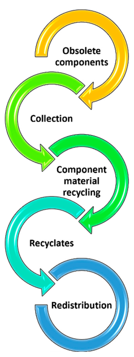
7.1. Waste Management in a Composite Form

Originally, composite structures as well as materials, primarily from the aerospace a well as automotive industries, were thrown away or burned when they reached the end of their useful lives. During the past decade, the great majority of countries in the European Union have ruled in support of laws prohibiting the dumping of hazardous waste in landfills. Concerning burning, the most concerning aspect is the possibility of hazardous byproducts being released into the environment (matrix) [206]. Recycling, although being the more environmentally friendly option, is only economically viable if and only if the worth of the recovered raw materials surpasses the cost of the recycling medium. Because of the reasons described in the following paragraphs, composites offer some particular challenges for recyclers in this situation.

7.2. Composite Materials Recycling Approach

Recycling composite materials on a large scale is a challenging job, owing to the limited methods that are presently accessible [206,207]. The anticipated quantities of outdated material, as well as the regulations that govern it, are driving the need for optimal composite material recycling. The general recycling system shown in the flowchart below (Figure 21) further discusses the fundamental elements that ensure functioning. Given that the required materials have a lower volume of production than conventional (isotropic) materials, the availability of outdated components products and manufacturing waste is critical for effective functioning. This may result in a lack of availability, raising the cost of operating the operation.
Dependent on the kind of composite materials, reprocessing may include mechanical, thermal or chemical methods. Enhanced product quality, environmental restrictions and processing costs are among the obstacles to be overcome. When compared to virgin composites, optimization will allow satisfactory levels of quality and affordability, thereby creating a market for recycled composites.

7.3. Mechanical Recycling

The end of life (EOL) composite is gradually reduced in size throughout these operations. The first stage is coarse cutting or crushing at a low speed (to approximately 100 mm). The second stage uses high-speed milling for fine grinding to decrease the size to nearly one-tenth of its original size, which is subsequently separated into matrix and fiber particles using separation methods. The fine particles of the waste composites are next separated into fiber-rich (coarser) and matrix-rich (finer) fractions using cyclones and sieves. The possible use of recycled glass fiber composite materials as a substitute for virgin reinforcing elements in new thermoset composites has been investigated [208]. The closed-loop mechanical recycling of dough and sheet moulding composites, which are widely utilised in the automobile industry, was investigated. A new air separation method was created to improve the mechanical recycling process and the gathering of usable fiber grades of recycled materials, called recyclate. When the characteristics of these recyclate fibers were directly compared to the properties of pristine fibers, it was discovered that the recyclate fibers were weaker and had a worse matrix interface. Mechanical treatment is considered easy, but it is energy expensive, and it results in short fibers with poor mechanical characteristics that are only utilised as filler reinforcement materials.

7.4. Thermal Recycling

7.4.1. Pyrolysis Recycling Technique

The polymer breaks down during pyrolysis, which occurs at elevated temperatures of 300–1000 C in the absence of oxygen, to generate an oil, a gas and a char product, leaving a solid residue. In addition, the fibers are recovered. It should be noted that greater temperatures have an impact on the quality of the resultant fiber. It has the benefit of possibly being able to use all of the by-products. The temperature control, in combination with the time spent on the process, is a critical parameter for effective depolymerisation. Due to the high cost of carbon fiber reinforced composites, pyrolysis recycling is a more cost-effective option.

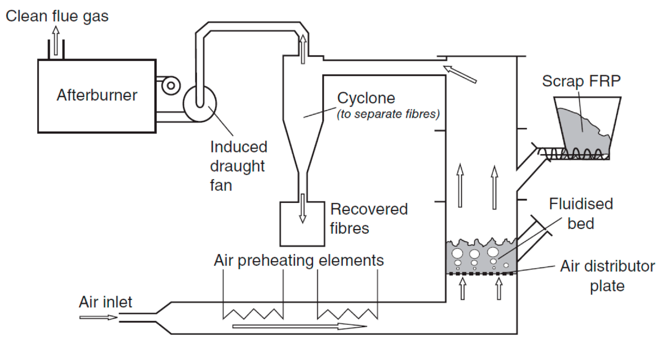
7.4.2. Fluidized Bed Combustion Recycling Process

The resin matrix is combusted, and the reinforcing fibers are reclaimed via a fluidised bed recycling method, as shown in Figure 22 [201]. The EOL material is broken down into tiny pellets (20–30 mm) and then fed into a fluid bed reactor, which achieves temperatures of up to 550 degrees Celsius depending on the composite recycled. The characteristics of recycled fibers, such as physical shape, fiber length and mechanical properties for fibers, are described in [207], which indicates a significant deterioration in general.

7.4.3. Chemical Recycling Process

The technique of chemical depolymerisation or matrix removal employing chemical dissolution reagents for recovering fibers is known as chemical recycling. Both fibers and matrices may be reclaimed via the chemical recycling method. The method may be used on a variety of fibers. In this instance, the recovered fibers have a slight loss of mechanical characteristics [208,209]. The matrix chemicals have a significant impact on the process’ efficiency. This highlights the necessity to ensure awareness of the EOL properties, which is a challenging job in an environment where a variety of composite materials is prevalent.

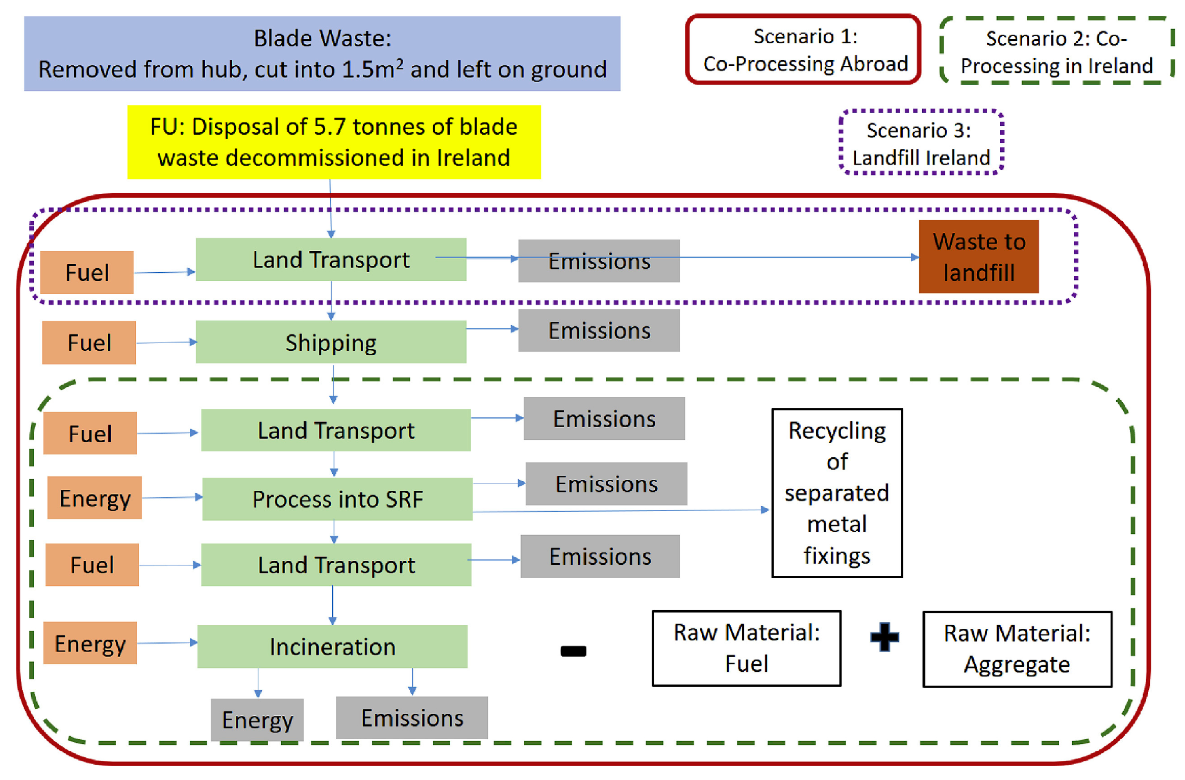
7.5. The Specific Sector

Large-scale wind turbines (up to 3 MW) typically include a three-blade rotor, which accounts for about 4% of the overall turbine weight, with 40% of that being composite [186]. Furthermore, about 10% of the composite is wasted during the production process, which is a considerable amount. At the end of the service life for such composite structures, which is usually 20 years, the total mass of composite trash from EOL wind turbines is expected to exceed 1 million tonnes. The fundamental nature of the issue to be addressed is that composite materials are inherently difficult to recycle. In order to find a solution, two aspects must be considered. The first is the creation of optimum recycling systems capable of maximising material and energy recovery. The second is the development of new composites with outstanding mechanical characteristics and the ability to be recycled. The above should be done in accordance with economies of scale, which are linked to the availability of EOL material, environmental regulations, overall cost and the possibility of new environmentally hazardous derivative substances, all of which will eventually determine the process’s long-term viability.

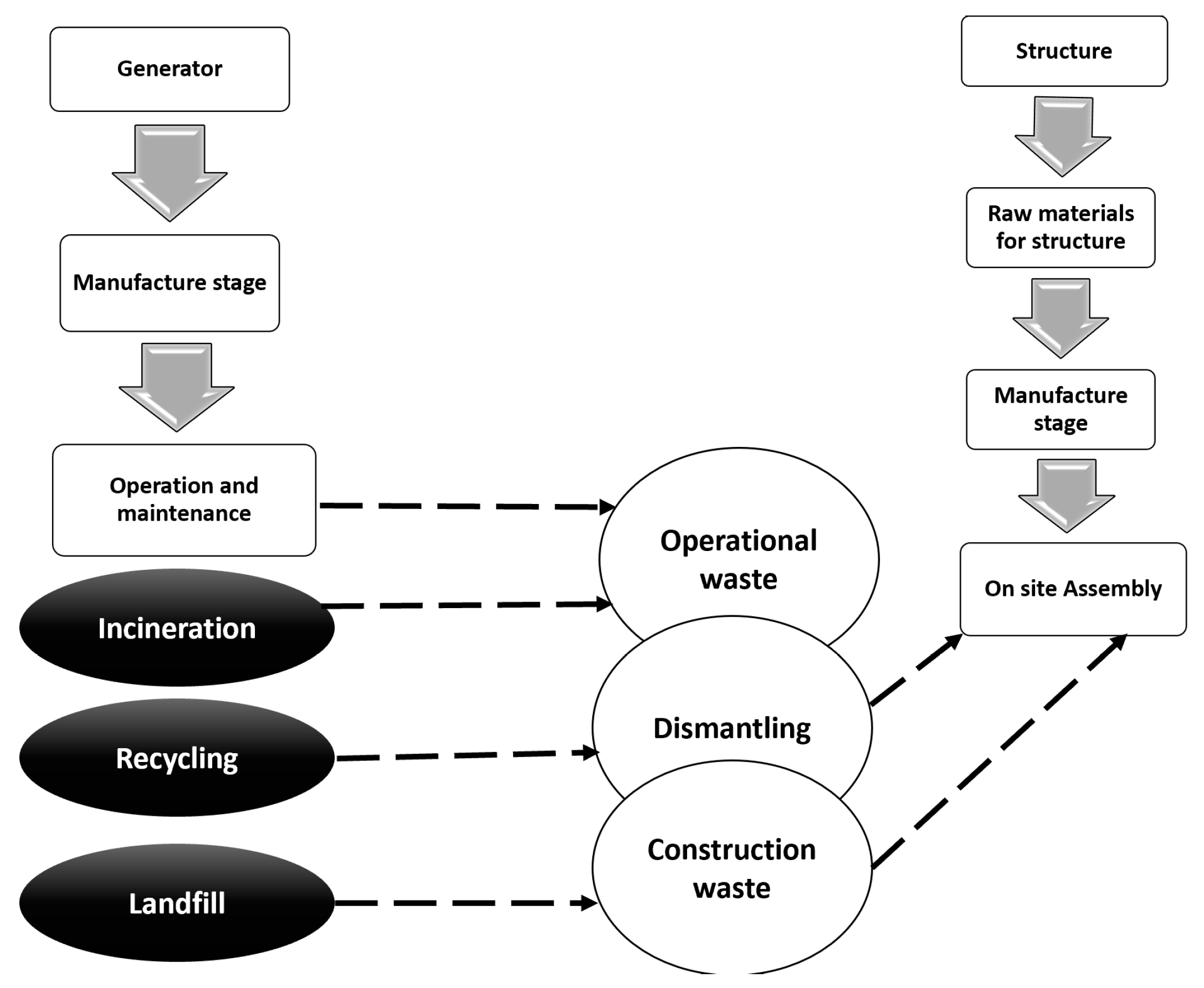
7.5.1. The Life Cycle Method

The life cycle assessment is a technique that may examine every direct and indirect effect of a product or service over its entire life cycle. The manufacturing and installation stages of renewable energy facilities have the greatest environmental effect. Figure 23 highlights the life cycle assessment for the turbine blades.
The efficiency of a wind turbine should be assessed after determining the balance between environmental effects throughout its lifetime and energy saved. The embodied energy of a wind turbine is the time it takes for it to produce energy equal to the energy spent over its entire life cycle, whereas the emission payback time is the time it takes for avoided emissions from the wind turbine to equal those released for manufacturing and all related processes.
There are many stages to the analysis. To begin, one must have a thorough understanding of the structure being examined (Figure 24). This is the total amount of energy used on the manufacturing, installation and ongoing maintenance of a system. Naturally, when considering big buildings or numerous units, energy spent on infrastructure must be taken into account. There are many phases to the life cycle inventory analysis. The resource inputs, all utilised materials and energy needed for the production of the various components of the wind turbine are all included in the inventory study. Energy input requirements include foundation manufacturing, transportation and on-site assembly operation and maintenance, as well as deconstruction and recycling at the end of service [210]. When it comes to wind turbines, blades are the most difficult part to recycle because of their shape. The EOL process, in particular, consists of a number of stages that begin with the planning of procedures and expenses. The elimination of the building is carried out in accordance with the project management, followed by the completion of secondary processes, such as logistics for the removed materials. Current waste management methods and choices are relevant to the post-decommissioning of composite materials, as are existing waste management procedures and options. Consequently, with precise information of the waste generation process, one may control the characterisation of composite materials as well as the collection, separation-selection, recycling or energy recovery and recirculation processes.

7.5.2. Materials

The total size of the construction is a significant element in determining the bill of materials for the project. Furthermore, the design and manufacturing trends for small and big turbines are distinct from one another. This is owing to the fact that the requirements for strength and fatigue loading are different. Because of the continuous dynamic stress applied to some wind turbine components, they experience significant cycle fatigue, which is often more than what would be anticipated in other high-performance engineering structures, such as aircrafts. As a result, material fatigue characteristics are taken into account throughout the design and selection of wind turbine components. There are new component innovations that will have a major impact on the patterns of material use. In general, lightweight materials are being used more often, particularly on moving components. As rotor size grows, the tendency will be towards materials with great strength and fatigue resistance. Various composites will most certainly be used in this sector as turbine designs continue to develop, which implies that a solution to the problem of industrial recycling capacity will be required, including for toxins contained in turbine parts that are released when materials are recovered or incinerated at extremely high temperatures [211]. The material used for the blades is fiber-reinforced plastics, which is a resin that produces toxic gases and must be carefully filtered after being recovered or incinerated at extremely high temperatures. Additionally, the dust generated by cutting operations produces a potentially dangerous working environment. Damaged buildings may expose people to a variety of different hazards, including airborne fibers and dust. According to the application or modification of the structure, there is a different level of risk for personnel exposure [212]. There are definitions for premanufacturing flies and dust, the cured structure, manufacturing/machining and post event assessment, among other things. When it comes to the recycling of composite materials, there seems to be a vacuum. Carbon fibers are very fine and readily broken when stretched, and they may form a fine dust when handled in any manner throughout any handling activities. Manufacturing, qualification, processing, testing and evaluation, as well as servicing and disposal, are all included. Typically, no combustion of the carbon fiber occurs; however, the resin may burn, causing the fiber to be dispersed throughout the structure. The ensuing fire creates containment and collection issues that need the use of hazard measures. The resulting plume should be deemed carcinogenic and should be avoided at all costs via proper ventilation.

7.6. Extension of Life of Turbine Blades

When a wind turbine is approaching the end of its service life, it may be more cost-effective to retrofit it in order to extend its service life rather than to shut it down and decommission it under certain situations. It is common for a thorough examination to establish that the most important internal subsystems (such as the generator and blades) must be replaced, while an exhaustive evaluation is required to evaluate the appropriateness and safety of the sustained subsystems [213]. It is normal for the tower to still be in good working order and to be utilised safely for many more years after it was built. The cost of common spares is typically between 5 percent (rotor hub) and 20 percent (blades) of the cost of a new wind turbine (WT) [214]. In 2014, a detailed study and posterior analysis of the wind farms (WFs) in the United Kingdom was conducted, and it was estimated that the majority of WTs would survive for about 25 years before they need to be updated [215]. It was also determined that the first set of WTs in the United Kingdom, which were installed in the 1990s and have now completed their normal service life, are still profitable due to the fact that their power production is approximately 75% of their nominal production; as a result, it was estimated that they may have another 5 years of profitable operation left in them. In [216], a study of several life extension scenarios was carried out in order to determine the feasibility of operational life extension as well as the environmental effect of such an extension via the use of life cycle assessment (LCA). In this study, life extension periods of 5 and 10 years were considered after a typical service life of 25 years was taken into consideration. The LCA research took into account energy generation as well as extra maintenance, such as materials and services, among other things. As previously stated, the higher the quality and management of the inspection and operation and maintenance operations of WTs, the greater the likelihood that they will be appropriate for life extension. According to [217], the cost of offshore operations and maintenance activities is presently two to five times higher than the cost of operations and maintenance onshore. According to certain sources, one of the reasons for this may be the extra work being put into developing WTs that can withstand the severity of the offshore environment and avoid those particular environmental hazards, which increases not only capital expenditure (CAPEX) but also O&M costs even more [218,219]. This is the reason why operators are now searching for methods to improve the efficiency of these turbines’ operations, which will result in a significant reduction in operating and maintenance expenses. In order to improve efficiency and, as a result, life extension, the use of structural health monitoring and condition monitoring (SHM/CM) systems in conjunction with smart loads management, as part of a condition -based maintenance (CBM) paradigm, is one of the most effective methods available [220]. CBM methods allow for the scheduling of maintenance operations and inspections based on the data collected by SHM/CM systems [221] and other sources. It is possible to schedule needed maintenance operations in advance and have them carried out at the offshore emplacement rather than waiting until a failure has occurred [222,223] by continuously monitoring the health of WTs’ structural components. At the moment, these technologies are being modified to work with offshore wind. SHM/CM systems are already extensively employed in certain subsystems, such as generators and gearboxes; however, other subsystems are still awaiting the creation of a framework that evaluates all of the gathered data and shows the health of the subsystem in question. When a specific degree of damage is recognised by the SHM system at an early stage, the operation of WTs depending on the health of the structure will enable for their deaeration to take place. This will lower the amount of electricity produced, but it will also lengthen the service life of the wind turbines, cut maintenance costs and improve the efficiency of wind farms in the process. According to certain calculations conducted by [217], when a turbine is deaerated, resulting in a 5 percent reduction in power output, a fatigue life extension in the blades may approach 300 percent, owing to a reduction of 10 percent in the equivalent loading. Furthermore, in order to accomplish the life extension of wind farms, a comprehensive failure modes and risk identification, as well as an evaluation of the variables that affect operation and maintenance costs, should be carried out in order to evaluate whether or not life extension is feasible.

7.7. Repowering

Repowering is the technique of either rebuilding old WTs with new ones that have higher rated power and efficiency or replacing the turbine while reusing the tower to generate more power and efficiency. The owner of a WF may, therefore, determine if repowering is a viable alternative in the last years of the WF’s operating life and under what circumstances it should be carried out. This choice should be based on the considerations listed below [224]:
  • The WF’s profitability is decreasing with time, as both performance and dependability deteriorate.
  • Profit expectations for both life extension and the various repowering alternatives are discussed in detail.
  • The cost–benefit ratio that repowering will provide as compared to the complete decommissioning of the wind farm and the recycling of the project’s components.
There are three distinct repowering options available, each of which is dependent on the current condition of the WT and may be described as follows:
  • The very same tower with a new, lower-capacity turbine: This option combines a smaller WT that may even generate lower electricity, requires less maintenance (resulting in higher availability) and has a nominal service life of an additional 25 years with the same tower that, because the turbine’s power has been reduced, will have fewer applied loads, hence a longer fatigue life.
  • Same tower having higher-capacity turbine that will generate more energy and survive an additional 25 years is combined with the same tower, which will be subjected to larger loads as a result of the increased power of the turbine, and its structural integrity should be carefully evaluated. Consequently, unless the structural integrity of the tower will be adequate to meet the new standards, this choice will often be unfavourable in the majority of instances.
  • Modern tower with a new, greater-capacity turbine: This option involves the decommissioning of the tower and nacelle in preparation for the commissioning of a new WT later on.
Using a portion of the existing infrastructure from the existing offshore wind farm (OWF) to lower the capital cost of the new one is a tenet of all three alternatives (after repowering). For example, the majority of the original subsea cables, as well as the existing grid connection, may be utilised in certain cases. However, if the capacity of the WT has been expanded, it is possible that the grid connection will need to be improved.
In order to repower, a separate financial procedure should be implemented, which will result in a second building phase as well as an operations and maintenance phase, with all of the ramifications that these phases involve [224]. In most cases, turbines are installed in high-wind resource areas where it is economically feasible to replace a turbine that has surpassed its normal service life with a new turbine that has the same or better characteristics than the one that was originally installed. Several instances of repowered WFs may be found in California, Nevada, the Netherlands and Denmark, among other places. Repowering is now going on in the United Kingdom, where RWE npower Renewables has been granted permission to carry out the repowering of one of Europe’s first onshore wind farms (WF). The project will consider reducing the number of WTs while simultaneously doubling the power generation, which means that the WF built in 1993 and consisting of 20 WTs will be transformed into a WF consisting of 7 WTs with a capacity of 17.5 MW, which accounts for more than twice the actual power generated each year [215,216].

7.8. Decommissioning

When service life extension or repowering are not financially viable options, the decommissioning of a WF is the last step of the project’s development. As a result, it is the least desired end-of-life situation. The primary goal of this step is to restore the seafloor to the state it was in before to the first deployment [224]. The decommissioning phase of a WF requires the transportation of all WT components from offshore to onshore and ultimately to their treatment site [225]. This is accomplished by boats and trucks. A WT will be completely dismantled if it is required to be completely decommissioned. First, all blades, the nacelle and the tower will be disassembled and hauled down by crane; next, its posterior components will be separated and reduced into smaller pieces appropriate for scrap [226]. It is expected that almost all of the WT material will be recycled. It should be noted that the qualification and personnel for the decommissioning operations that were utilised are similar to those that were used during the commissioning stage. The recycling scenario provided by [216] illustrates how the offshore wind farm (OWF) is divided among the decommissioning EOL alternatives available for decommissioning. First, the offshore wind farm is dismantled and divided into its constituent parts, with the energy consumption assumed to be similar to that of the commissioning phase. After that, waste treatment is carried out according to the kind of material that was utilised. Waste treatment may be broken down into three categories: recycling, landfilling and incineration. The consequences and costs of decommissioning and recycling must be understood by all parties involved (municipalities, small landowners and WT developers).

8. Conclusions

The future of energy generation is highly dependent on the practicality of expanding current energy obtained from wind. This goal can only be obtained when the turbine blades for wind energy systems are designed properly. The performance of these wind turbines can only be enhanced when their material compositions are light in weight, durable, able to resist fatigue, high in stiffness and capable of resisting failure damage. The blades of wind turbines are produced via combined impact and cyclic loading. Most wind turbines are manufactured from fiber-reinforced polymer composites. Most of the research efforts are geared towards producing wind turbines that are strong, easy to recycle and eco-friendly and have strong resistance to damage. Today, the research community has come out with the latest epoxy resin systems that have low viscosity. Other characteristics of these new materials for wind turbines are their excellent wetting of fibers and support infusion pressure in vacuum-assisted resin transfer moulding (VARTM), and these reduce defects at the manufacturing stage. The wind turbine blades are enhanced due to the automation of some component deposition in VARTM, reducing defect possibilities, as well. The world has also seen the evolution of resins with quicker curing times and reduced temperatures for the curing process. An alternative to the common E-glass fibers are carbon fibers. Natural glass, as well as basalt, are all alternatives to E-glass fibers. Some demerits of carbon fibers are their price, less compressional strength and easy misalignment, even though their high stiffness is promising. A solution to curb this challenge is combining carbon and E glass. This increases the stiffness and does not increase the cost. Thermoplastics also have some merits compared to thermosets, such as recyclability. Wind turbine blade strength is determined by the damage at the micro level in fibers and the interface of the matrix. This concludes the fact that, if these microscale characteristics are improved, the life span, as well as the strength of the material, is likely to surge up appreciably. It is possible to achieve this feat through nanoscale structure modifications. The future of wind turbines in terms of energy generation from this report concludes that material composition, especially for the turbine blades, affects the overall cost of the wind turbine, the lifetime of the turbines and the efficiency of the turbine.

Author Contributions

Conceptualization, A.G.O., M.A.A. and T.W.; methodology, K.E., E.T.S., T.S. and A.B.; formal analysis, A.G.O., M.A.A. and T.W.; investigation, K.E., E.T.S. and A.B.; resources, A.G.O., M.A.A. and T.W.; data curation, K.E., T.S., E.T.S. and A.B.; writing—original draft preparation, A.G.O., T.W., M.A.A., T.S., K.E., E.T.S. and A.B.; writing—review and editing, T.W., M.A.A., K.E. and A.G.O.; supervision, A.G.O. and M.A.A.; project administration, T.W. All authors have read and agreed to the published version of the manuscript.

Funding

This research received no external funding.

Conflicts of Interest

The authors declare no conflict of interest.

References

  1. Wilberforce, T.; Olabi, A.; Sayed, E.T.; Elsaid, K.; Abdelkareem, M.A. Progress in carbon capture technologies. Sci. Total Environ. 2021, 761, 143203. [Google Scholar] [CrossRef]
  2. Abdelkareem, M.A.; Lootah, M.A.; Sayed, E.T.; Wilberforce, T.; Alawadhi, H.; Yousef, B.A.; Olabi, A. Fuel cells for carbon capture applications. Sci. Total Environ. 2021, 769, 144243. [Google Scholar] [CrossRef]
  3. Elsaid, K.; Kamil, M.; Sayed, E.T.; Abdelkareem, M.A.; Wilberforce, T.; Olabi, A. Environmental impact of desalination technologies: A review. Sci. Total Environ. 2020, 748, 141528. [Google Scholar] [CrossRef] [PubMed]
  4. Elsaid, K.; Sayed, E.T.; Abdelkareem, M.A.; Baroutaji, A.; Olabi, A. Environmental impact of desalination processes: Mitigation and control strategies. Sci. Total Environ. 2020, 740, 140125. [Google Scholar] [CrossRef]
  5. Olabi, A.; Abdelkareem, M.A.; Wilberforce, T.; Sayed, E.T. Application of graphene in energy storage device—A review. Renew. Sustain. Energy Rev. 2021, 135, 110026. [Google Scholar] [CrossRef]
  6. Tanveer, W.H.; Abdelkareem, M.A.; Kolosz, B.W.; Rezk, H.; Andresen, J.; Cha, S.W.; Sayed, E.T. The role of vacuum based technologies in solid oxide fuel cell development to utilize industrial waste carbon for power production. Renew. Sustain. Energy Rev. 2021, 142, 110803. [Google Scholar] [CrossRef]
  7. Rabaia, M.K.H.; Abdelkareem, M.A.; Sayed, E.T.; Elsaid, K.; Chae, K.-J.; Wilberforce, T.; Olabi, A. Environmental impacts of solar energy systems: A review. Sci. Total Environ. 2021, 754, 141989. [Google Scholar] [CrossRef] [PubMed]
  8. Sayed, E.T.; Wilberforce, T.; Elsaid, K.; Rabaia, M.K.H.; Abdelkareem, M.A.; Chae, K.-J.; Olabi, A. A critical review on environmental impacts of renewable energy systems and mitigation strategies: Wind, hydro, biomass and geothermal. Sci. Total Environ. 2021, 766, 144505. [Google Scholar] [CrossRef]
  9. Bauer, A.; Menrad, K. Standing up for the Paris Agreement: Do global climate targets influence individuals’ greenhouse gas emissions? Environ. Sci. Policy 2019, 99, 72–79. [Google Scholar]
  10. Abdelkareem, M.A.; Assad, M.E.H.; Sayed, E.T.; Soudan, B. Recent progress in the use of renewable energy sources to power water desalination plants. Desalination 2018, 435, 97–113. [Google Scholar] [CrossRef]
  11. History of Wind Turbines. Available online: http://xn--drmstrre-64ad.dk/wp-content/wind/miller/ (accessed on 5 October 2018).
  12. Webpage of Poul La Cour Museum. Available online: http://www.poullacour.dk (accessed on 5 October 2018).
  13. Ostachowicz, W.; McGugan, M.; Schröder-Hinrichs, J.U.; Luczak, M. MARE-MINT: New Materials and Reliability in Offshore Wind Turbine Technology; Springer Nature: Berlin/Heidelberg, Germany, 2016. [Google Scholar]
  14. Mishnaevsky, L., Jr.; Brøndsted, P.; Nijssen, R.; Lekou, D.J.; Philippidis, T.P. Materials of large wind turbine blades: Recent results in testing and modeling. Wind Energy 2012, 15, 83–97. [Google Scholar] [CrossRef]
  15. Mishnaevsky, L.; Branner, K.; Petersen, H.N.; Beauson, J.; McGugan, M.; Sørensen, B.F. Materials for wind turbine blades: An. overview. Materials 2017, 10, 1285. [Google Scholar] [CrossRef] [PubMed] [Green Version]
  16. Novais, R.M.; Carvalheiras, J.; Capela, M.; Seabra, M.; Pullar, R.; Labrincha, J. Incorporation of glass fiber fabrics waste into geopolymer matrices: An eco-friendly solution for off-cuts coming from wind turbine blade production. Constr. Build. Mater. 2018, 187, 876–883. [Google Scholar] [CrossRef]
  17. Brøndsted, P.; Nijssen, R.P.L. Advances in Wind Turbine Blade Design and Materials; Woodhead Publishing: Cambridge, UK, 2013. [Google Scholar] [CrossRef]
  18. Walker, K. Renewable Energy Embraces Graphene: Improved Wind Turbine Technology. Available online: http://www.azocleantech.com/article.aspx?ArticleID=455 (accessed on 8 October 2018).
  19. Watson, J.C.; Serrano, J.C. Composite materials for wind blades. Wind Syst. Mag. 2010, 46, 46–51. [Google Scholar]
  20. Mohamed, M.H.; Wetzel, K.K. 3D woven carbon/glass hybrid spar cap for wind turbine rotor blade. J. Sol. Energy Eng. 2006, 128, 562–573. [Google Scholar] [CrossRef]
  21. Debel, C. Identification of damage types in wind turbine blades tested to failure. In Proceedings of the Dansk Metallurgisk Selskabs Vintermøde, Kolding, Denmark, 7–9 January 2004. [Google Scholar]
  22. Dorigato, A. Recycling of thermosetting composites for wind blade application. Adv. Ind. Eng. Polym. Res. 2021, 4, 116–132. [Google Scholar] [CrossRef]
  23. Garolera, A.C.; Madsen, S.F.; Nissim, M.; Myers, J.D.; Holboell, J. Lightning damage to wind turbine—Newline blades from wind farms in the U.S. IEEE Trans. Power Deliv. 2014, 31, 1043–1049. [Google Scholar] [CrossRef]
  24. Yasuda, Y.; Yokoyama, S.; Minowa, M.; Satoh, T. Classification of lightning damage to wind turbine blades. IEEJ Trans. Electr. Electron. Eng. 2012, 7, 559–566. [Google Scholar] [CrossRef]
  25. Sareen, A.; Sapre, C.A.; Selig, M.S. Effects of leading edge erosion on wind turbine blade performance. Wind Energy 2013, 17, 1531–1542. [Google Scholar] [CrossRef]
  26. Keegan, M.H.; Nash, D.H.; Stack, M.M. On erosion issues associated with the leading edge of wind turbine blades. J. Phys. D Appl. Phys. 2013, 46, 383001. [Google Scholar] [CrossRef] [Green Version]
  27. Cattin, R. Icing of wind turbines. Vindforsk projects, a survey of the development and research needs. Elforsk Rep. 2012, 12, 13. [Google Scholar]
  28. Zhu, S. An Automated Method for the Layup of Fiberglass Fabric. Ph.D. Thesis, Iowa State University, Ames, IA, USA, 2015. [Google Scholar] [CrossRef]
  29. Teuwen, J.K.R.; Joncas, S.; Bersee, H.E.N. Vacuum Infused Thermoplastic Composites for Wind Turbine Blades. 2008. Available online: https://windpower.sandia.gov/2008BladeWorkshop/PDFs/Tues-14-Teuwen.pdf (accessed on 5 April 2021).
  30. Vacuum Assisted Resin. Transfer Molding. Available online: https://usa.exportersindia.com/rhino-linings-industrial-company5141729/vacuum-assisted-resin-transfer-molding-3202656.htm (accessed on 23 May 2021).
  31. Liu, H.-C.; Liu, L.; Liu, N. Risk evaluation approaches in failure mode and effects analysis: A literature review. Expert Syst. Appl. 2013, 40, 828–838. [Google Scholar] [CrossRef]
  32. Mishnaevsky, L., Jr.; Brøndsted, P. Statistical modelling of compression and fatigue damage of unidirectional fiber rein-forced composites. Compos. Sci. Technol. 2009, 69, 477–484. [Google Scholar] [CrossRef]
  33. Ashby, M. Material Process and Selection Charts, 2nd ed.; Reed Educational and Professional Publishing Ltd.: London, UK, 2009. [Google Scholar]
  34. Akil, H.M.; Omar, M.F.; Mazuki, A.A.M.; Safiee, S.; Ishak, Z.; Abu Bakar, A. Kenaf fiber reinforced composites: A review. Mater. Des. 2011, 32, 4107–4121. [Google Scholar] [CrossRef]
  35. Holmes, J.W.; Sørensen, B.F.; Brøndsted, P. Reliability of wind turbine blades: An overview of materials testing. In Proceedings of the Wind Power Shanghai, Shanghai, China, 1–3 November 2007; pp. 310–315. [Google Scholar]
  36. Holmes, J.W.; Brøndsted, P.; Sørensen, B.F.; Jiang, Z.; Sun, Z.; Chen, X. Development of a bamboo-based composite as a sustainable green material for wind turbine blades. Wind. Eng. 2009, 33, 197–210. [Google Scholar] [CrossRef]
  37. Bakri, B.; Chandrabakty, S.; Alfriansyah, R.; Dahyar, A. Potential coir fiber composite for small wind turbine blade application. Int. J. Smart Mater. Mechatron. 2016, 2, 42–44. [Google Scholar] [CrossRef]
  38. Sparnins, E. Mechanical Properties of Flax Fibers and Their Composites. Ph.D. Thesis, Luleå University of Technology, Luleå, Sweden, 2009. [Google Scholar]
  39. Nasir, A.A.; Azmi, A.; Khalil, A.N.M. Measurement and optimisation of residual tensile strength and delamination damage of drilled flax fiber reinforced composites. Measurements 2015, 75, 298–307. [Google Scholar] [CrossRef]
  40. Prabhakaran, R.T. Future materials for wind turbine blades-A critical review. In Proceedings of the International Conference on Wind Energy: Materials, Engineering and Policies (WEMEP-2012), Hyderabad, India, 22–23 November 2012. [Google Scholar]
  41. Fecko, D. High strength glass reinforcements still being discovered. Reinf. Plast. 2006, 50, 40–44. [Google Scholar] [CrossRef]
  42. Grand, J.A. Wind power blades energize composites manufacturing. Plast. Technol. 2008, 54, 68–75. [Google Scholar]
  43. Mishnaevsky, L., Jr.; Dai, G. Hybrid carbon/glass fiber composites: Micromechanical analysis of structure–damage re-sistance relationships. Comput. Mater. Sci. 2014, 81, 630–640. [Google Scholar] [CrossRef]
  44. Dai, G.; Mishnaevsky, L., Jr. Fatigue of hybrid carbon/glass composites: 3D Computational modelling. Compos. Sci. Technol. 2014, 94, 71–79. [Google Scholar] [CrossRef]
  45. Prabhakaran, D.; Andersen, T.L.; Markussen, C.M.; Madsen, B.; Lilholt, H. Tensile and compression properties of hybrid composites—A comparative study. In Proceedings of the 19th International Conference on Composite Materials (ICCM19), Montréal, QC, Canada, 28 July–2 August 2013. [Google Scholar]
  46. Chiang, M.Y.; Wang, X.; Schultheisz, C.R.; He, J. Prediction and three-dimensional Monte-Carlo simulation for tensile properties of unidirectional hybrid composites. Compos. Sci. Technol. 2005, 65, 1719–1727. [Google Scholar] [CrossRef]
  47. Gutans, J.; Tamuzs, V. Strength probability of unidirectional hybrid composites. Theor. Appl. Fract. Mech. 1987, 7, 193–200. [Google Scholar] [CrossRef]
  48. Mikkelsen, L.P.; Mishnaevsky, L., Jr. Computational modelling of materials for wind turbine blades: Selected DTU wind energy activities. Materials 2017, 10, 1278. [Google Scholar] [CrossRef] [Green Version]
  49. Summerscales, J.; Short, D. Carbon fiber and glass fiber hybrid reinforced plastics. Composites 1978, 9, 157–166. [Google Scholar] [CrossRef]
  50. Sinha, R.; Acharya, P.; Freere, P.; Sharma, R.; Ghimire, P.; Mishnaevsky, L. Selection of nepalese timber for small wind turbine blade construction. Wind. Eng. 2010, 34, 263–276. [Google Scholar] [CrossRef]
  51. Nijssen, R.P.L. Fatigue Life Prediction and Strength Degradation of Wind Turbine Rotor Blade Composites; Contractor Report SAND2006-7810P; Sandia National Laboratorie: Albuquerque, NM, USA, 2006. [Google Scholar]
  52. Joncas, S. Thermoplastic Composite Wind Turbine Blades: An Integrated Design Approach. Ph.D. Thesis, Delft University of Technology, Delft, The Netherlands, 2010. [Google Scholar]
  53. Lystrup, A. Hybrid Yarn for Thermoplastic Fiber Composites. Summary of Technical Results; Risoe National Lab.: Roskilde, Denmark, 1998. [Google Scholar]
  54. Dai, G.; Mishnaevsky, L. Damage evolution in nanoclay-reinforced polymers: A three-dimensional computational study. Compos. Sci. Technol. 2013, 74, 67–77. [Google Scholar] [CrossRef]
  55. Zhou, H.; Mishnaevsky, L.; Yi, H.; Liu, Y.; Hu, X.; Warrier, A.; Dai, G. Carbon fiber/carbon nanotube reinforced hierarchical composites: Effect of CNT distribution on shearing strength. Compos. Part B Eng. 2016, 88, 201–211. [Google Scholar] [CrossRef] [Green Version]
  56. Ma, P.-C.; Zhang, Y. Perspectives of carbon nanotubes/polymer nanocomposites for wind blade materials. Renew. Sustain. Energy Rev. 2014, 30, 651–660. [Google Scholar] [CrossRef]
  57. Loos, M.; Yang, J. Carbon Nanotube-Reinforced Epoxy Composites for Wind Turbine Blades. ANTEC 2011 PENG-11-2010-0518. (PDF) Epoxy/Carbon Nanotube Composites for Wind Turbine Blades. Available online: Researchgate.net (accessed on 16 June 2021).
  58. Yavari, F.; Rafiee, M.; Rafiee, J.; Yu, Z.-Z.; Koratkar, N. Dramatic increase in fatigue life in hierarchical graphene composites. ACS Appl. Mater. Interfaces 2010, 2, 2738–2743. [Google Scholar] [CrossRef] [PubMed] [Green Version]
  59. Merugula, L.; Khanna, V.; Bakshi, B.R. Reinforced wind turbine blades—An environmental life cycle evaluation. Environ. Sci. Technol. 2012, 46, 9785–9792. [Google Scholar] [CrossRef]
  60. Merugula, L.A.; Khanna, V.; Bakshi, B.R. Comparative life cycle assessment: Reinforcing wind turbine blades with carbon nanofibers. In Proceedings of the 2010 IEEE International Symposium on Sustainable Systems and Technology, Arlington, VA, USA, 17–19 May 2010. [Google Scholar]
  61. Kinloch, A.J.; Taylor, A.; Techapaitoon, M.; Teo, W.S.; Sprenger, S. From matrix nano- and micro-phase tougheners to composite macro-properties. Philos. Trans. R. Soc. A Math. Phys. Eng. Sci. 2016, 374, 20150275. [Google Scholar] [CrossRef] [Green Version]
  62. Pontefisso, A.; Mishnaevsky, L. Nanomorphology of graphene and CNT reinforced polymer and its effect on damage: Micromechanical numerical study. Compos. Part B Eng. 2016, 96, 338–349. [Google Scholar] [CrossRef]
  63. Rafiee, R.; Ghorbanhosseini, A. Stochastic Modeling of CNT-Grown Fibers. In Micro and Nano Technologies, Carbon Nanotube-Reinforced Polymers; Rafiee, R., Ed.; Elsevier: Amsterdam, The Netherlands, 2018; pp. 521–540. ISBN 9780323482219. [Google Scholar] [CrossRef]
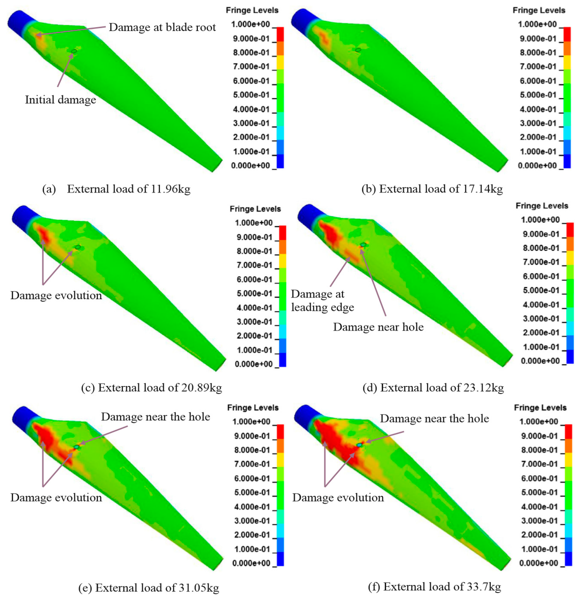
  64. Ye, J.; Chu, C.; Cai, H.; Hou, X.; Shi, B.; Tian, S.; Chen, X.; Ye, J. A multi-scale model for studying failure mechanisms of composite wind turbine blades. Compos. Struct. 2019, 212, 220–229. [Google Scholar] [CrossRef] [Green Version]
  65. Andrew, J.J.; Srinivasan, S.M.; Arockiarajan, A.; Dhakal, H.N. Parameters influencing the impact response of fiber-reinforced polymer matrix composite materials: A critical review. Compos. Struct. 2019, 224, 111007. [Google Scholar] [CrossRef]
  66. Jefferson, A.J.; Arumugam, V.; Dhakal, H.N. Repair of Polymer Composites: Methodology, Techniques, and Challenges; Woodhead Publishing: Cambridge, UK, 2018. [Google Scholar]
  67. Jefferson, A.J.; Arumugam, V.; Santulli, C.; Jennifers, A.; Poorani, M. Failure modes of GFRP after multiple impacts determined by acoustic emission and digital image correlation. J. Eng. Technol. 2015, 6, 29–51. [Google Scholar]
  68. Tiberkak, R.; Bachene, M.; Rechak, S.; Necib, B. Damage prediction in composite plates subjected to low velocity impact. Compos. Struct. 2008, 83, 73–82. [Google Scholar] [CrossRef]
  69. Bull, D.; Scott, A.; Spearing, S.; Sinclair, I. The influence of toughening-particles in CFRPs on low velocity impact damage resistance performance. Compos. Part A Appl. Sci. Manuf. 2014, 58, 47–55. [Google Scholar] [CrossRef] [Green Version]
  70. Hongkarnjanakul, N.; Rivallant, S.; Bouvet, C.; Miranda, A. Permanent indentation characterization for low-velocity impact modelling using three-point bending test. J. Compos. Mater. 2013, 48, 2441–2454. [Google Scholar] [CrossRef] [Green Version]
  71. Tita, V.; De Carvalho, J.; Vandepitte, D. Failure analysis of low velocity impact on thin composite laminates: Experimental and numerical approaches. Compos. Struct. 2008, 83, 413–428. [Google Scholar] [CrossRef]
  72. Vieille, B.; Casado, V.M.; Bouvet, C. Influence of matrix toughness and ductility on the compression-after-impact behavior of woven-ply thermoplastic-and thermosetting-composites: A comparative study. Compos. Struct. 2014, 110, 207–218. [Google Scholar] [CrossRef]
  73. Davies, G.; Zhang, X. Impact damage prediction in carbon composite structures. Int. J. Impact Eng. 1995, 16, 149–170. [Google Scholar] [CrossRef]
  74. Alcock, B.; Cabrera, N.O.; Barkoula, N.M.; Wang, Z.; Peijs, T. The effect of temperature and strain rate on the impact performance of recyclable all-polypropylene compo-sites. Compos. Part B Eng. 2008, 39, 537–547. [Google Scholar] [CrossRef]
  75. Naik, N.; Shrirao, P.; Reddy, B. Ballistic impact behaviour of woven fabric composites: Formulation. Int. J. Impact Eng. 2006, 32, 1521–1552. [Google Scholar] [CrossRef]
  76. Andrew, J.J.; Arumugam, V.; Santulli, C. Effect of post-cure temperature and different reinforcements in adhesive bonded repair for damaged glass/epoxy composites under multiple quasi-static indentation loading. Compos. Struct. 2016, 143, 63–74. [Google Scholar] [CrossRef]
  77. Børvik, T. An Introduction to Impact and Penetration Dynamics; Department of Structural Engineering, Norwegian University of Science and Technology: Trondheim, Norway, 2003. [Google Scholar]
  78. Olsson, R. Mass criterion for wave controlled impact response of composite plates. Compos. Part A Appl. Sci. Manuf. 2000, 31, 879–887. [Google Scholar] [CrossRef]
  79. Olsson, R. Closed form prediction of peak load and delamination onset under small mass impact. Compos. Struct. 2003, 59, 341–349. [Google Scholar] [CrossRef]
  80. Rehman, S.; Alam, M.; Alhems, M.L. A review of wind-turbine structural stability, failure and alleviation. In Proceedings of the Advances in Civil, Environmental, & Materials Research (ACEM18) Songdo Convensia, Incheon, Korea, 27–31 August 2018. [Google Scholar]
  81. Mothers against Wind Turbine Inc. 2016 Wind Turbine Accident Report. Available online: https://mothersagainstturbines.com/2016/04/07/2016-wind-turbine-accident-report/comment-page-1/ (accessed on 3 May 2021).
  82. Alam, M.; Zhou, Y.; Yang, H.X.; Guo, H.; Mi, J. The ultra-low Reynolds number airfoil wake. Exp. Fluids 2009, 48, 81–103. [Google Scholar] [CrossRef]
  83. Qin, B.; Alam, M.; Zhou, Y. Two tandem cylinders of different diameters in cross-flow: Flow-induced vibration. J. Fluid Mech. 2017, 829, 621–658. [Google Scholar] [CrossRef]
  84. Kim, S.; Alam, M.; Maiti, D.K. Wake and suppression of flow-induced vibration of a circular cylinder. Ocean. Eng. 2018, 151, 298–307. [Google Scholar] [CrossRef]
  85. Caithness Wind Farm Information Forum. Summary of Wind Turbine Accident Data to 31 March 2021. Available online: http://www.caithnesswindfarms.co.uk/AccidentStatistics.htm (accessed on 2 May 2021).
  86. Kress, C.; Chokani, N.; Abhari, R. Downwind wind turbine yaw stability and performance. Renew. Energy 2015, 83, 1157–1165. [Google Scholar] [CrossRef]
  87. Abdallah, I.; Natarajan, A.; Sørensen, J. Impact of uncertainty in airfoil characteristics on wind turbine extreme loads. Renew. Energy 2015, 75, 283–300. [Google Scholar] [CrossRef]
  88. Lin, Y.; Tu, L.; Liu, H.; Li, W. Fault analysis of wind turbines in China. Renew. Sustain. Energy Rev. 2016, 55, 482–490. [Google Scholar] [CrossRef]
  89. Tavner, P.; Greenwood, D.M.; Whittle, M.W.G.; Gindele, R.; Faulstich, S.; Hahn, B. Study of weather and location effects on wind turbine failure rates. Wind Energy 2012, 16, 175–187. [Google Scholar] [CrossRef]
  90. Wilson, G.; McMillan, D. Assessing wind farm reliability using weather dependent failure rates. J. Phys. Conf. Ser. 2014, 524. [Google Scholar] [CrossRef] [Green Version]
  91. Sathe, A.; Mann, J.; Barlas, A.; Bierbooms, W.; Van Bussel, G. Influence of atmospheric stability on wind turbine loads. Wind Energy 2012, 16, 1013–1032. [Google Scholar] [CrossRef]
  92. Nuta, E.; Christopoulos, C.; Packer, J.A. Methodology for seismic risk assessment for tubular steel wind turbine towers: Application to Canadian seismic environment. Can. J. Civ. Eng. 2011, 38, 293–304. [Google Scholar] [CrossRef]
  93. Myers, A.T.; Gupta, A.; Ramirez, C.M.; Chioccarelli, E. Evaluation of the seismic vulnerability of tubular wind tur-bine towers. In Proceedings of the 15th World Conference on Earthquake Engineering, Lisbon, Portugal, 24–28 September 2012. [Google Scholar]
  94. Witcher, D. Seismic analysis of wind turbines in the time domain. Wind. Energy 2004, 8, 81–91. [Google Scholar] [CrossRef]
  95. Stamatopoulos, G.N. Response of a wind turbine subjected to near-fault excitation and comparison with the Greek Aseismic Code provisions. Soil Dyn. Earthq. Eng. 2013, 46, 77–84. [Google Scholar] [CrossRef]
  96. Nebenführ, B.; Davidson, L. Prediction of wind-turbine fatigue loads in forest regions based on turbulent LES inflow fields. Wind Energy 2016, 20, 1003–1015. [Google Scholar] [CrossRef]
  97. Sadowski, A.J.; Camara, A.; Málaga-Chuquitaype, C.; Dai, K. Seismic analysis of a tall metal wind turbine support tower with realistic geometric imperfections. Earthq. Eng. Struct. Dyn. 2017, 46, 201–219. [Google Scholar] [CrossRef] [Green Version]
  98. Chou, J.-S.; Chiu, C.-K.; Huang, I.-K.; Chi, K.-N. Failure analysis of wind turbine blade under critical wind loads. Eng. Fail. Anal. 2013, 27, 99–118. [Google Scholar] [CrossRef]
  99. Chen, X.; Xu, J.Z. Structural failure analysis of wind turbines impacted by super typhoon Usagi. Eng. Fail. Anal. 2016, 60, 391–404. [Google Scholar] [CrossRef]
  100. Collier, B.; DeMarco, T.; Fearey, P. A defined process for project postmortem review. IEEE Softw. 1996, 13, 65–72. [Google Scholar] [CrossRef]
  101. Dingsøyr, T. Postmortem reviews: Purpose and approaches in software engineering. Inf. Softw. Technol. 2005, 47, 293–303. [Google Scholar] [CrossRef] [Green Version]
  102. Bjørnson, F.O.; Wang, A.I.; Arisholm, E. Improving the effectiveness of root cause analysis in post mortem analysis: A controlled experiment. Inf. Softw. Technol. 2009, 51, 150–161. [Google Scholar] [CrossRef]
  103. Gacougnolle, J.L.; Castagnet, S.; Werth, M. Post-mortem analysis of failure in polyvinylidene fluoride pipes tested under constant pressure in the slow crack growth regime. Eng. Fail. Anal. 2006, 13, 96–109. [Google Scholar] [CrossRef]
  104. Carcedo, J.; Fernández, A.O.; Ortiz, A.; Carrascal, I.A.; Delgado, F.; Ortiz, F.; Arroyo, A. Post-mortem estimation of temperature distribution on a power transformer: Physicochemical and mechanical approaches. Appl. Therm. Eng. 2014, 70, 935–943. [Google Scholar] [CrossRef] [Green Version]
  105. Queiroga, J.A.; Campos, K.S.; Silva, E.; Souza, D.F.; Nunes, E.H.; Vasconcelos, W. Post mortem study of refractory lining used in FCC units. Eng. Fail. Anal. 2013, 34, 290–299. [Google Scholar] [CrossRef]
  106. Asghar, Z.; Requena, G. Three dimensional post-mortem study of damage after compression of cast Al-Si Al-Loys. Mater. Sci. Eng. A 2014, 591, 136–143. [Google Scholar] [CrossRef]
  107. Ishihara, T.; Yamaguchi, A.; Takahara, K.; Mekaru, T.; Matsuura, S. An analysis of damaged wind turbines by typhoon Maemi. In Proceedings of the Sixth Asia Pacific Conference on Wind Engineering (APCWE-VI), Seoul, Korea, 12–14 September 2005. [Google Scholar]
  108. Chou, J.-S.; Tu, W.-T. Failure analysis and risk management of a collapsed large wind turbine tower. Eng. Fail. Anal. 2011, 18, 295–313. [Google Scholar] [CrossRef]
  109. Zhang, Z.; Yin, Z.; Han, T.; Tan, A.C. Fracture analysis of wind turbine main shaft. Eng. Fail. Anal. 2013, 34, 129–139. [Google Scholar] [CrossRef] [Green Version]
  110. Jensen, F.M.; Weaver, P.; Cecchini, L.; Stang, H.; Nielsen, R.F. The Brazier effect in wind turbine blades and its influence on design. Wind Energy 2011, 15, 319–333. [Google Scholar] [CrossRef]
  111. Overgaard, L.C.T.; Lund, E.; Thomsen, O.T. Structural collapse of a wind turbine blade. Part A: Static test and equivalent single layered models. Compos. Part A Appl. Sci. Manuf. 2010, 41, 257–270. [Google Scholar] [CrossRef]
  112. Yang, W.; Tavner, P.J.; Crabtree, C.J.; Feng, Y.; Qiu, Y. Wind turbine condition monitoring: Technical and commercial challenges. Wind Energy 2014, 17, 673–693. [Google Scholar] [CrossRef] [Green Version]
  113. Chen, X.; Zhao, W.; Zhao, X.L.; Xu, J.Z. Preliminary failure investigation of a 52.3 m glass/epoxy composite wind turbine blade. Eng. Fail. Anal. 2014, 44, 345–350. [Google Scholar] [CrossRef]
  114. Marín, J.; Barroso, A.; París, F.; Cañas, J. Study of fatigue damage in wind turbine blades. Eng. Fail. Anal. 2009, 16, 656–668. [Google Scholar] [CrossRef]
  115. Lacalle, R.; Cicero, S.; Álvarez, J.; Cicero, R.; Madrazo, V. On the analysis of the causes of cracking in a wind tower. Eng. Fail. Anal. 2011, 18, 1698–1710. [Google Scholar] [CrossRef]
  116. Karthikeyan, N.; Kalidasa, M.K.; Arun, K.S.; Rajakumar, S. Review of aerodynamic developments on small horizontal axis wind turbine blade. Renew. Sustain. Energy Rev. 2015, 42, 801–822. [Google Scholar] [CrossRef]
  117. Chehouri, A.; Younes, R.; Ilinca, A.; Perron, J. Review of performance optimization techniques applied to wind turbines. Appl. Energy 2015, 142, 361–388. [Google Scholar] [CrossRef]
  118. Yang, R.; He, Y.; Zhang, H. Progress and trends in nondestructive testing and evaluation for wind turbine composite blade. Renew. Sustain. Energy Rev. 2016, 60, 1225–1250. [Google Scholar] [CrossRef]
  119. Burton, T.; Jenkins, N.; Sharpe, D.; Bossanyi, E. Wind Energy Handbook; John Wiley & Sons: Hoboken, NJ, USA, 2001. [Google Scholar]
  120. Guo, X.; Guan, Z.-D.; Nie, H.-C.; Tan, R.-M.; Li, Z.-S. Damage tolerance analysis of adhesively bonded composite single lap joints containing a debond Flaw. J. Adhes. 2016, 93, 216–234. [Google Scholar] [CrossRef]
  121. Song, M.-G.; Kweon, J.-H.; Choi, J.-H.; Byun, J.-H.; Shin, S.-J.; Lee, T.-J. Effect of manufacturing methods on the shear strength of composite single-lap bonded joints. Compos. Struct. 2010, 92, 2194–2202. [Google Scholar] [CrossRef]
  122. Wu, G.; Qin, Z.; Zhang, L.; Yang, K. Strain response analysis of adhesively bonded extended composite wind turbine blade suffering unsteady aerodynamic loads. Eng. Fail. Anal. 2017, 85, 36–49. [Google Scholar] [CrossRef]
  123. Caselitz, P.; Giebhardt, J.; Mevenkamp, M. Application of condition monitoring systems in wind energy convertors. In Proceedings of the European Wind Energy Conference (EWEC’97), Dublin, Ireland, 6–9 October 1997; pp. 579–582. [Google Scholar]
  124. Brusa, E.; Amati, N. Condition monitoring of rotors on active magnetic bearings (AMB) fed by induction motors. In Proceedings of the IEEE/ASME Advanced Engineering Mechatronics, Como, Italy, 8–12 July 2001; pp. 750–756. [Google Scholar]
  125. Yang, W.; Tavner, P.J.; Wilkinson, M.R. Condition monitoring and fault diagnosis of a wind turbine synchronous generator drive train. IET Renew. Power Gener. 2009, 3, 1–11. [Google Scholar] [CrossRef]
  126. Andrawus, J.A.; Watson, J.; Kishk, M.; Adam, A. The selection of a suitable maintenance strategy for wind turbines. Wind Eng. 2006, 30, 471–486. [Google Scholar] [CrossRef]
  127. Kusiak, A.; Zhang, Z.; Verma, A. Prediction, operations, and condition monitoring in wind energy. Energy 2013, 60, 1–12. [Google Scholar] [CrossRef]
  128. Lu, B.; Li, Y.; Wu, X.; Yang, Z. A review of recent advances in wind turbine condition monitoring and fault diagnosis. In Proceedings of the 2009 Power Electronics and Machines in Wind Applications (PEMWA 2009), Lincoln, NE, USA, 24–26 June 2009; pp. 1–7. [Google Scholar]
  129. Tsai, C.-S.; Hsieh, C.-T.; Huang, S.-J. Enhancement of damage-detection of wind turbine blades via CWT-Based approaches. IEEE Trans. Energy Convers. 2006, 21, 776–781. [Google Scholar] [CrossRef]
  130. Kaylani, H.; Alkhalidi, A.; Al-Oran, F.; Alhababsah, Q. Component-level failure analysis using multi-criteria hybrid approach to ensure reliable operation of wind turbines. Wind Eng. 2021. [Google Scholar] [CrossRef]
  131. Böger, L.; Wichmann, M.H.; Meyer, L.O.; Schulte, K. Load and health monitoring in glass fiber reinforced composites with an electrically conductive nanocomposite epoxy matrix. Compos. Sci. Technol. 2008, 68, 1886–1894. [Google Scholar] [CrossRef] [Green Version]
  132. Popa, L.M.; Jensen, B.-B.; Ritchie, E.; Boldea, I. Condition monitoring of wind generators. In Proceedings of the 38th IAS Annual Meeting on Industry Applications Conference, Salt Lake City, UT, USA, 12–16 October 2003; pp. 1839–1846. [Google Scholar]
  133. Rumsey, M.A.; Paquette, J.A. Structural health monitoring of wind turbine blades. Proc. SPIE 2008, 6933, 69330E. [Google Scholar] [CrossRef]
  134. Arrigan, J.; Pakrashi, V.; Basu, B.; Nagarajaiah, S. Control of flapwise vibrations in wind turbine blades using semi-active tuned mass dampers. Struct. Control. Health Monit. 2010, 18, 840–851. [Google Scholar] [CrossRef]
  135. Cotton, I.; Jenkins, N.; Pandiaraj, K. Lightning protection for wind turbine blades and bearings. Wind Energy 2001, 4, 23–37. [Google Scholar] [CrossRef]
  136. Li, H.; Diaz, H.; Soares, C.G. A developed failure mode and effect analysis for floating offshore wind turbine support structures. Renew. Energy 2021, 164, 133–145. [Google Scholar] [CrossRef]
  137. Shen, X.; Zhu, X.; Du, Z. Wind turbine aerodynamics and loads control in wind shear flow. Energy 2011, 36, 1424–1434. [Google Scholar] [CrossRef]
  138. Hansen, M.H. How Hard Can It Be to Pitch a Wind Turbine Blade? RISO Lab, Denmark Technical University. Available online: www.risoe.dtu.dk/rispubl/art/2007_321_presentation.pdf (accessed on 12 August 2020).
  139. Yang, X.; Li, J.; Liu, W.; Guo, P. Petri net model and reliability evaluation for wind turbine hydraulic variable pitch systems. Energies 2011, 4, 978–997. [Google Scholar] [CrossRef] [Green Version]
  140. Watton, J. Modelling, Monitoring and Diagnostic Techniques for Fluid Power Systems; Springer: Berlin/Heidelberg, Germany, 2007. [Google Scholar]
  141. Crabtree, C.J.; Feng, Y.; Tavner, P.J. Detecting incipient wind turbine gearbox failure: A signal analysis method for on-line condition monitoring. In Proceedings of the European Wind Energy Conference (EWEC 2010), 19th Pril, Warsaw, Poland, 20–23 April 2010. [Google Scholar]
  142. Shen, G.; Xiang, D.; Zhu, K.; Jiang, L.; Shen, Y.; Li, Y. Fatigue failure mechanism of planetary gear train for wind turbine gearbox. Eng. Fail. Anal. 2018, 87, 96–110. [Google Scholar] [CrossRef]
  143. Wilkinson, M.R.; Spinato, F.; Tavner, P.J. Condition monitoring of generators & other subassemblies in wind turbine drive trains. In Proceedings of the 2007 IEEE International Symposium on Diagnostics for Electric Machines, Power Electronics and Drives, Cracow, Poland, 6–8 September 20007; pp. 388–392. [Google Scholar] [CrossRef]
  144. McNiff, B. The gearbox reliability. In Proceedings of the 2nd Sandia National Laboratories Wind Turbine Reliability Workshop, Albuquerque, NM, USA, 17–18 September 2007. [Google Scholar]
  145. Tchakoua, P.; Wamkeue, R.; Ouhrouche, M.; Slaoui-Hasnaoui, F.; Tameghe, T.A.; Ekemb, G. Wind turbine condition moni-toring: State-of-the-art review, new trends, and future challenges. Energies 2014, 7, 2595–2630. [Google Scholar] [CrossRef] [Green Version]
  146. Guo, P.; Bai, N. Wind turbine gearbox condition monitoring with AAKR and moving window statistic methods. Energies 2011, 4, 2077–2093. [Google Scholar] [CrossRef] [Green Version]
  147. Mobley, R.K. An Introduction to Predictive Maintenance; Elsevier: Amsterdam, The Netherlands, 2002. [Google Scholar] [CrossRef]
  148. Faiz, J.; Ojaghi, M. Different indexes for eccentricity faults diagnosis in three-phase squirrel-cage induction motors: A review. Mechatronics 2009, 19, 2–13. [Google Scholar] [CrossRef]
  149. Orsagh, R.F.; Lee, H.; Watson, M.; Byington, C.S.; Powers, J. Advanced Vibration Monitoring for Wind Turbine Health Management. Available online: http://rlwinc.com/Re-sources/TechnicalPublicationPDFs/PowerandIndustrial/Impact_PI_IMSASD-AWEA%20HUMS.pdf (accessed on 15 January 2021).
  150. Thomson, W.T.; Gilmore, R.J. Motor current signature analysis to detect faults in induction motordrives: Fundamentals, data interpretation and industrial case histories. In Proceedings of the 32nd Turbomachinery Symposium, Houston, TX, USA, 9–11 September 2003; pp. 45–156. [Google Scholar]
  151. Cameron, J.R.; Thomson, W.T.; Dow, A.B. Vibration and current monitoring for detecting airgap eccentricity in large induction motors. IEEE Proc. B Electr. Power Appl. 1986, 133, 155–163. [Google Scholar] [CrossRef]
  152. Mehrjou, M.R.; Mariun, N.; Marhaban, M.H.; Misron, N. Rotor fault condition monitoring techniques for squirrel-cage in-duction machine. Mech. Syst. Signal Process 2011, 25, 2827–2848. [Google Scholar] [CrossRef]
  153. Ilonen, J.; Kamarainen, J.-K.; Lindh, T.; Ahola, J.; Kalviainen, H.; Partanen, J. Diagnosis tool for motor condition monitoring. IEEE Trans. Ind. Appl. 2005, 41, 963–971. [Google Scholar] [CrossRef]
  154. Lu, B.; Sharma, S.K. A literature review of IGBT fault diagnostic and protection methods for power inverters. IEEE Trans. Ind. Appl. 2009, 45, 1770–1777. [Google Scholar] [CrossRef]
  155. Màrquez-Dominguez, S.; Sørensen, J.D. Fatigue reliability and calibration of fatigue design factors for offshore wind turbines. Energies 2012, 5, 1816–1834. [Google Scholar] [CrossRef] [Green Version]
  156. Sørensen, J.D. Reliability assessment of wind turbines. In Proceedings of the European Safety and Reliability Conference (ESREL 2013), Amsterdam, The Netherlands, 29 September–2 October 2013. [Google Scholar]
  157. Van der Woude, C.; Narasimhan, S. A study on vibration isolation for wind turbine structures. Eng. Struct. 2014, 60, 223–234. [Google Scholar] [CrossRef]
  158. Fleming, K.; Weltman, A.; Randolph, M.; Elson, K. Piling Engineering; CRC Press: Boca Raton, FL, USA, 2009. [Google Scholar]
  159. Andersen, K.H.; Puech, A.A.; Jardine, R.J. Design for cycling loading: Piles and other foundations. In Proceedings of the 18th International Conference on Soil Mechanics and Geotechnical Engineering (ICSMGE), Paris, France, 2–6 September 2013. [Google Scholar]
  160. Brennan, F.; Kolios, A. Structural integrity considerations for the H2Ocean multi modal wind-wave platform. In Proceedings of the European Wind Energy Association (EWEA) Conference and Exhibition 2014, Barcelona, Spain, 10–13 March 2014. [Google Scholar]
  161. Sørensen, B.F.; Jørgensen, E.; Debel, C.P.; Jensen, F.M.; Jensen, H.M.; Jacobsen, T.K.; Halling, K. Improved Design of Large Wind Turbine Blade of Fiber Composites Based on Studies of Scale Effects (Phase 1); Summary Report; Risø-R-1390(EN); Riso National Laboratory: Roskilde, Denmark, 2004; 36p. [Google Scholar]
  162. Jensen, F.M.; Kling, A.; Sorensen, J.D. Change in Failure type when wind turbines blades scale up. In Proceedings of the Sandia Wind Turbine Workshop; 2012. Available online: https://energy.sandia.gov/wp-content//gallery/uploads/2B-A-1-Jensen1.pdf (accessed on 15 January 2021).
  163. Branner, K.; Ghadirian, A. Database about blade faults. DTU Wind Energy. (DTU Wind Energy E; No. 0067). 2014. Available online: https://core.ac.uk/download/pdf/43253602.pdf (accessed on 5 August 2021).
  164. Mone, C.; Hand, M.; Bolinger, M.; Rand, J.; Heimiller, D.; Ho, J. Cost of Wind Energy Review; U.S. Department of Energy Office of Scientific and Technical Information: Oak Ridge, TN, USA, 2017. [CrossRef]
  165. Carlos, S.; Sánchez, A.; Martorell, S.; Marton, I. Onshore wind farms maintenance optimization using a stochastic model. Math. Comput. Model. 2013, 57, 1884–1890. [Google Scholar] [CrossRef]
  166. Guess, F.M.; Hoyland, A.; Rausand, M. System reliability theory: Models and statistical methods. J. Am. Stat. Assoc. 1996, 91, 436. [Google Scholar] [CrossRef]
  167. Glavind, L.; Olesen, I.S.; Skipper, B.F.; Kristensen, M. Fiber-optical grating sensors for wind turbine blades: A review. Opt. Eng. 2013, 52, 030901. [Google Scholar] [CrossRef] [Green Version]
  168. García Márquez, F.P.; Tobias, A.M.; Pinar Pérez, J.M.; Papaelias, M. Condition monitoring of wind turbines: Techniques and methods. Renew. Energy 2012, 46, 169–178. [Google Scholar] [CrossRef]
  169. Rogelj, D.S.J.; Jiang, K.; Fifita, S.; Forster, P.; Ginzburg, V.; Handa, C.; Kheshgi, H.; Kobayashi, S.; Kriegler, E.; Mundaca, L.; et al. Mitigation Pathways Compatible with 1.5 °C in the Context of Sustainable Development, Global Warming of 1.5 °C. In An IPCC Special Report on the Impacts of Global Warming of 1.5 °C above Pre-industrial Levels and Related Global Greenhouse Gas Emission Pathways, in the Context of Strengthening the Global Response to the Threat of Climate Change, Sustainable Development, and Efforts to Eradicate Poverty; Intergovernmental Panel on Climate Change: Geneva, Switzerland, 2018. [Google Scholar]
  170. Luz, T.; Moura, P. 100% Renewable energy planning with complementarity and flexibility based on a multi-objective assess-ment. Appl. Energy 2019, 255, 113819. [Google Scholar] [CrossRef]
  171. Jacobson, M.Z.; Delucchi, M.A.; Bauer, Z.A.; Goodman, S.C.; Chapman, W.E.; Cameron, M.; Bozonnat, C.; Chobadi, L.; Clonts, H.A.; Enevoldsen, P.; et al. 100% Clean and renewable wind, water, and sunlight all-sector energy roadmaps for 139 countries of the world. Joule 2017, 1, 108–121. [Google Scholar] [CrossRef] [Green Version]
  172. IRENA. Renewable Energy Statistics 2019; International Renewable Energy Agency: Abu Dhabi, United Arab Emirates, 2019. [Google Scholar]
  173. Kost, C.; Shammugam, S.; Jülch, V.; Nguyen, H.-T.; Schlegl, T. Levelized Cost of Electricity Renewable Energy Technologies; Fraunhofer Institute for Solar Energy Systems—ISE: Freiburg im Breisgau, Germany, 2018. [Google Scholar]
  174. Aldersey-Williams, J.; Rubert, T. Levelised cost of energy—A theoretical justification and critical assessment. Energy Policy 2018, 124, 169–179. [Google Scholar] [CrossRef]
  175. Elia, A.; Taylor, M.; Gallachóir, B.; Rogan, F. Wind turbine cost reduction: A detailed bottom-up analysis of innovation drivers. Energy Policy 2020, 147, 111912. [Google Scholar] [CrossRef]
  176. Clarke, L.; Weyant, J.; Edmonds, J. On the sources of technological change: What do the models assume? Energy Econ. 2008, 30, 409–424. [Google Scholar] [CrossRef]
  177. Junginger, M.; Hittinger, E.; Williams, E.; Wiser, R. Chapter 6—Onshore wind energy. In Technological Learning in the Transition to a Low-Carbon Energy System; Junginger, M., Louwen, A., Eds.; Elsevier: Amsterdam, The Netherlands, 2020; pp. 87–102. [Google Scholar]
  178. Samadi, S. The experience curve theory and its application in the field of electricity generation technologies—A literature re-view. Renew. Sustain. Energy Rev. 2018, 82, 2346–2364. [Google Scholar] [CrossRef] [Green Version]
  179. Yu, Y.; Li, H.; Che, Y.; Zheng, Q. The price evolution of wind turbines in China: A study based on the modified multi-factor learning curve. Renew. Energy 2017, 103, 522–536. [Google Scholar] [CrossRef]
  180. Hayashi, D.; Huenteler, J.; Lewis, J.I. Gone with the wind: A learning curve analysis of Chinas’ wind power industry. Energy Policy 2018, 120, 38–51. [Google Scholar] [CrossRef]
  181. Candelise, C.; Winskel, M.; Gross, R. The dynamics of solar PV costs and prices as a challenge for technology forecasting. Renew. Sustain. Energy Rev. 2013, 26, 96–107. [Google Scholar] [CrossRef] [Green Version]
  182. Qiu, Y.; Anadon, L.D. The price of wind power in China during its expansion: Technology adoption, learning-by-doing, economies of scale, and manufacturing localization. Energy Econ. 2012, 34, 772–785. [Google Scholar] [CrossRef]
  183. Lin, B.; He, J. Learning curves for harnessing biomass power: What could explain the reduction of its cost during the expan-sion of China? Renew. Energy 2016, 99, 280–288. [Google Scholar] [CrossRef]
  184. Neij, L. Cost development of future technologies for power generation—A study based on experience curves and complemen-tary bottom-up assessments. Energy Policy 2008, 36, 2200–2211. [Google Scholar] [CrossRef]
  185. Kavlak, G.; McNerney, J.; Trancik, J.E. Evaluating the causes of cost reduction in photovoltaic modules. Energy Policy 2018, 123, 700–710. [Google Scholar] [CrossRef] [Green Version]
  186. McNerney, J.; Farmer, J.D.; Trancik, J.E. Historical costs of coal-fired electricity and implications for the future. Energy Policy 2011, 39, 3042–3054. [Google Scholar] [CrossRef] [Green Version]
  187. IEA. Global Energy Review 2020. Available online: https://www.iea.org/reports/global-energy-review-2020/renewables (accessed on 17 January 2021).
  188. Obane, H. Forecasting photovoltaic and wind energy capital costs in Japan: A Bayesian approach. Energy Procedia 2019, 158, 3576–3582. [Google Scholar] [CrossRef]
  189. Irena. Renewable Energy Technologies: Cost Analysis Series; International Renewable Energy Agency: Abu Dhabi, United Arab Emirates, 2012; Volume 1. [Google Scholar]
  190. Steffen, B.; Beuse, M.; Tautorat, P.; Schmidt, T.S. Experience curves for operations and maintenance costs of renewable energy technologies. Joule 2020, 4, 359–375. [Google Scholar] [CrossRef]
  191. El-Thalji, I.; Liyanage, J.P. On the operation and maintenance practices of wind power asset A status review and observations. J. Qual. Mainten. Eng. 2012, 18, 232–266. [Google Scholar] [CrossRef]
  192. Zhang, Z.; Ding, X.; Liu, M.; Zeng, J. Based on wavelet transform of fault diagnosis and analysis of wind generator transmission system. J. Basic Sci. Eng. 2011, 19 (Suppl. S1), 210–218. [Google Scholar]
  193. Kusiak, A.; Li, W. The prediction and diagnosis of wind turbine faults. Renew. Energy 2011, 36, 16–23. [Google Scholar] [CrossRef]
  194. Brandão, R.F.M.; Carvalho, J.A.B.; Barbosa, F.P.M. Condition monitoring of the wind turbine generator slip ring. In Proceedings of the Universities Power Engineering Conference, London, UK, 4–7 September 2012. [Google Scholar]
  195. Tamilselvan, P.; Wang, Y.; Wang, P. Optimization of wind turbines operation and maintenance using failure prognosis. In Proceedings of the PHM 2012–2012 IEEE International Conference on Prognostics and Health Management: Enhancing Safety, Efficiency, Availability, and Effectiveness of Systems through PHM Technology and Application, Conference Program, Denver, CO, USA, 18–21 June 2012. [Google Scholar]
  196. Lau, B.C.P.; Ma, E.W.M.; Pecht, M. Review of offshore wind turbine failures and fault prognostic methods. In Proceedings of the PHM 2012–2012 IEEE International Conference on Prognostics and Health Management: Enhancing Safety, Efficiency, Availability, and Effectiveness of Systems through PHM Technology and Application, Conference Program, Beijing, China, 23–25 May 2012. [Google Scholar]
  197. Hofmann, M.A. Review of decision support models for offshore wind farms with an emphasis on operation and maintenance strategies. Wind. Eng. 2011, 35, 1–15. [Google Scholar] [CrossRef]
  198. Tracht, K.; Westerholt, J.; Schuh, P. Spare parts planning for offshore wind turbines subject to restrictive maintenance conditions. Procedia Cirp. 2013, 7, 563–568. [Google Scholar] [CrossRef] [Green Version]
  199. Yang, W.; Court, R.; Jiang, J. Wind turbine condition monitoring by the approach of SCADA data analysis. Renew. Energy 2013, 53, 365–376. [Google Scholar] [CrossRef]
  200. Aguilar, S.; Telles, G.R.; Medina, P.; Quaresma, B.; Cyrino, F.L.; Castro, R. Wind power generation: A review and a research agenda. J. Clean Prod. 2019, 218, 850–870. [Google Scholar]
  201. Kalkanis, K.; Psomopoulos, C.; Kaminaris, S.; Ioannidis, G.; Pachos, P. Wind turbine blade composite materials—End of life treatment methods. Energy Procedia 2019, 157, 1136–1143. [Google Scholar] [CrossRef]
  202. Witik, R.A.; Payet, J.; Michaud, V.; Ludwig, C.; Månson, J.-A.E. Assessing the life cycle costs and environmental performance oflight-weight materials in automobile applications. Compos. Part A 2011, 42, 1694–1709. [Google Scholar] [CrossRef]
  203. Suzuki, T.; Takahashi, J. Prediction of energy intensity of carbon fiber reinforced plastics for mass-produced passenger car. In Proceedings of the 9th Japan International SAMPE Symposium, Japan, Tokyo, 29 November–2 December 2005; pp. 14–19. [Google Scholar]
  204. Das, S. Life cycle assessment of carbon fiber-reinforced polymer composites. Int. J. Life Cycle Assess 2011, 16, 268–282. [Google Scholar] [CrossRef]
  205. Goodship, V. Management, Recycling and Reuse of Waste Composites; Woodhead Publishing: Cambridge, UK, 2010. [Google Scholar] [CrossRef]
  206. Henshaw, J.M. Recycling and disposal of polymer–matrix composites. In ASM Handbook, Volume 21: Composites; Miracle, D.B., Donaldson, S.L., Eds.; ASM International®: Materials Park, OH, USA, 2001; pp. 1006–1012. [Google Scholar]
  207. Pickering, S.J. Recycling technologies for thermoset composite materials—Current status. Compos. Part A Appl. Sci. Manuf. 2006, 37, 1206–1215. [Google Scholar] [CrossRef]
  208. Pickering, S.J. Thermal methods for recycling waste composites. In Management, Recycling and Reuse of Waste Composites; Goodship, V., Ed.; WP and CRC Press: Cambridge, UK, 2010; pp. 65–101. [Google Scholar]
  209. Nagle, A.J.; Delaney, E.L.; Bank, L.C.; Leahy, P.G. A Comparative Life Cycle Assessment between landfilling and Co-Processing of waste from decommissioned Irish wind turbine blades. J. Clean. Prod. 2020, 277, 123321. [Google Scholar] [CrossRef]
  210. Papadakis, N. Designing composite wind turbine blades disposal recycling and reuse. In Management, Recycling and Reuse of Waste Composites; Goodship, V., Ed.; WP and CRC Press: Cambridge, UK, 2010; pp. 443–457. [Google Scholar]
  211. Lee, Y.-M.; Tzeng, Y.-E.; Su, C.-L. Life cycle assessment of wind power utilization in Taiwan. In Proceedings of the 7th International Conference on EcoBalance, Tsukuba, Japan, 14–16 November 2006. [Google Scholar]
  212. Andersen, P.D.; Bonou, A.; Beauson, J.; Brøndsted, P. Recycling of wind turbines. In DTU International Energy Report 2014: Wind Energy—Drivers and Barriers for Higher Shares of Wind in the Global Power Generation Mix; Larsen, H., Sønderberg, P.L., Eds.; Technical University of Denmark: Lyngbly, Denmark, 2014; pp. 91–97. [Google Scholar]
  213. Operational and Maintenance Costs for Wind Turbines. Available online: http://www.windmeasurementinternational.com/wind-turbines/om-turbines.php (accessed on 12 April 2021).
  214. Renewable Energy Technologies: Cost Analysis Series. Volume 1 Power Sector Issue 5/5 Wind Power. 2012. Available online: https://www.irena.org/DocumentDownloads/Publications/RE_Technologies_Cost_Analysis-WIND_POWER.pdf (accessed on 3 January 2020).
  215. Staffell, I.; Green, R. How does wind farm performance decline with age? Renew. Energy 2014, 66, 775–786. [Google Scholar] [CrossRef] [Green Version]
  216. Energy Economics. Statistical Review of World Energy. Available online: https://www.bp.com/en/global/corporate/energy-economics/statistical-review-of-world-energy/electricity.html (accessed on 22 July 2021).
  217. Griffith, D.T.; Yoder, N.C.; Resor, B.; White, J.; Paquette, J. Structural health and prognostics management for the enhance-ment of OWT operations and maintenance strategies. Wind Energy 2014, 17, 1737–1751. [Google Scholar] [CrossRef]
  218. Levitt, A.C.; Kempton, W.; Smith, A.P.; Musial, W.; Firestone, J. Pricing offshore wind power. Energy Policy 2011, 39, 6408–6421. [Google Scholar] [CrossRef]
  219. Musial, W.; Ram, B. Large-Scale Offshore Wind Energy for the United State: Assessment of Opportunities and Barriers; No. NREL/TP-500-40745; National Renewable Energy Laboratory (NREL): Golden, CO, USA, 2010. [Google Scholar]
  220. Griffith, D.T.; Yoder, N.C.; Resor, B.; White, J.; Paquette, J.; Ogilvie, A.; Peters, V. Prognostic control to enhance offshore wind turbine operation and maintenance strategies. In Proceedings of the European Wind Energy Conference (EWEA) Annual Event, Copenhagen, Denmark, 16–19 April 2012. [Google Scholar]
  221. Besnard, F.; Fischer, K.; Bertling, L. Reliability-centered asset maintenance: A step towards enhanced reliability, availability, and profitability of wind power plants. In Proceedings of the IEEE PES Innovative Smart Grid Technologies Conference Europe (ISGT Europe), Gothenburg, Sweden, 11–13 October 2010. [Google Scholar]
  222. Amirat, Y.; Benbouzid, M.E.H.; Bensaker, B.; Wamkeue, R. Condition monitoring and fault diagnosis in wind energy conver-sion systems: A review. In Proceedings of the 2007 IEEE International Electric Machines and Drives Conference, Antalya, Turkey, 3–5 May 2007; pp. 1434–1439. [Google Scholar]
  223. Ciang, C.C.; Lee, J.-R.; Bang, H.-J. Structural health monitoring for a wind turbine system: A review of damage detection methods. Meas. Sci. Technol. 2008, 19, 122001. [Google Scholar] [CrossRef] [Green Version]
  224. Energy for Sustainable Development (ESD) Ltd. for Greenpeace. Offshore Wind, Onshore Jobs: A New Industry for Britain; Energy for Sustainable Development (ESD) Ltd. for Greenpeace: London, UK, 2009; Available online: yumpu.com (accessed on 3 May 2020).
  225. Tsai, L. An Integrated Assessment of Offshore Wind Farm Siting: A Case Study in the Great Lakes of Michigan. Ph.D. Thesis, University of Michigan, Ann Arbor, MI, USA, 2013. [Google Scholar]
  226. Aakre, D.; Hangen, R. Wind Turbine Considerations for Landowners. NDSU Extension Service; North Dakota State University: Fargo, ND, USA, 2009; Available online: http://www.ag.ndsu.edu/pubs/agecon/market/ec1394.pdf (accessed on 12 March 2020).
Figure 1. Components of a wind turbine.
Energies 14 05241 g001
Figure 2. Wind turbine blade manufacturing process: (a) hand lay-up [28], (b) vacuum infusion or prepregging [29], (c) vacuum-assisted resin transfer moulding (VARTM) [30].
Energies 14 05241 g002
Figure 3. Wind turbine blade materials [33].
Energies 14 05241 g003
Figure 4. Natural Fiber classifications, adapted from [33,34].
Energies 14 05241 g004
Figure 5. Hybrid composite (a) aligned [48] and (b) misaligned [48]. (c) Image of the hybrid composite crack [43].
Energies 14 05241 g005
Figure 6. Critical stress against carbon fiber fractions in hybrid composites [43].
Energies 14 05241 g006
Figure 7. An image of carbon fiber with carbon nano tube reinforcement [63].
Energies 14 05241 g007
Figure 8. Damage of the matrix for composite wind turbine blade [64].
Energies 14 05241 g008
Figure 9. Deterioration mechanisms caused by impact loading (a) higher, (b) medium and (c) lower energy [65].
Energies 14 05241 g009
Figure 10. Factors that affect impact response.
Energies 14 05241 g010
Figure 11. Various categories of impacts (a) Very short impact time (b) Short impact time (c) Long impact time [78].
Energies 14 05241 g011
Figure 12. Varying response (a) boundary and (b) wave [79].
Energies 14 05241 g012
Figure 13. Yearly statistics on wind turbine damages around the world [81].
Energies 14 05241 g013
Figure 14. Annual data on blade and tower defects are compared [81].
Energies 14 05241 g014
Figure 15. Yearly rate of failure for wind turbine having a daily average wind sped at hub height [90].
Energies 14 05241 g015
Figure 16. Damages in the aeroshell and box girder; sketches of found failure modes in a wind turbine blade purposefully tested to failure [161].
Energies 14 05241 g016
Figure 17. Forms of wind turbine maintenance [166].
Energies 14 05241 g017
Figure 18. Evaluation of wind turbine cost [175].
Energies 14 05241 g018
Figure 19. The economics of wind energy.
Energies 14 05241 g019
Figure 20. Overview of wind energy O&M cost fields.
Energies 14 05241 g020
Figure 21. Diagram for a composite material recycling process.
Energies 14 05241 g021
Figure 22. Schematics of fluidized bed recycling process [201].
Energies 14 05241 g022
Figure 23. Wind turbine blades life cycle assessment boundary conditions [209].
Energies 14 05241 g023
Figure 24. Fundamental LCA model for the generator and overall structure of a wind turbine showing wastes and corresponding disposal/recycling solutions [201].
Energies 14 05241 g024
Table 1. Failure modes of wind turbine blades [163].
Mode of FailureImageClassificationReason for Failure
Interlaminar failure Energies 14 05241 i001V2–V3Brazier effect, bending moment
Delamination–Faulty injection Energies 14 05241 i002V1Wear
Peeling/Wear Energies 14 05241 i003V1Wear
Erosion of the sealing of the root V2Wear
Flaking of the topcoat Energies 14 05241 i004V1Air bubbles from the manufacturing/poor quality
Missing external parts Energies 14 05241 i005V2–V3Flaking and external objects impact
Fine cracks in topcoat V1Low quality of material
Transverse cracks from trailing edge V2–V3 Poor design
Transverse cracks on blade surface Energies 14 05241 i006V2–V3Poor design
Front edge cracks (transverse and longitudinal) Energies 14 05241 i007
Web failure V3Brazier effect, bending moment, poor design
Fatigue failure in root connection V3Poor design
Fatigue failure in root transition area V1–V2
Fatigue failure in bond lines, longitudinal cracks in the trailing edge Energies 14 05241 i008V1–V2Transversal shear distortion, deformation of trailing edge panels, trailing edge buckling
UV effect on the fibers V1Wear, flaking
Lightning damage Energies 14 05241 i009V3Lightning
Tower hit by blade V3High tip deflection
Balsa/composite cracking (transverse and longitudinal)
Transport damage Energies 14 05241 i010V0–V3
Complete separation V0
Where V0: Observation, no harm, V1: Damage to be repaired at an opportunity, V2: Damage must be repaired as soon as possible and V3: Serious damage. The turbine is stopped.
Table 2. For modules and subsystems of wind turbines, a summary of potential malfunction mechanisms and associated monitoring techniques [145] is given. (AE: Acoustic emission, OA: Oil analysis, SM: Strain measurement, SPM: Shock pulse method).
Wind Turbine SubsystemsCompositionPotential FailuresMonitoring Technique
RotorBladesDeterioration, cracking and adjustment errorUltrasound, and active thermographyTorque, AE, SM and VI
BearingsSpalling, wear, defect of bearing shells and rolling elementVibration, OA, AE, SPM and performance monitoring
ShaftFatigue and crack formationVibration
DrivetrainMain shaft bearingWear and high vibrationVibration, SPM, temperature and AETorque, power signal analysis, thermography, AE and performance monitoring
Mechanical brakeLocking positionTemperature
GearboxWearing, fatigue, oil leakage, insufficient lubrication, braking in teeth, displacement and eccentricity of toothed wheelsTemperature, vibration, SPM, OA and AE
GeneratorWearing, electrical problems, slip rigs, winding damage, rotor asymmetries, bar break, overheating and over speedGenerated effect, temperature, vibration, SPM, torque, power signal analysis, electrical effects, performance monitoring and thermography
Auxiliary systemPitch systemPitch motor problem-
Hydraulic systemPump motor problems and oil leakagePerformance monitoring
SensorsBroken and wrong indicationThermography
Electrical systemControl systemShort circuit, component fault and bad connectionCurrent consumption and temperatureArc guard, temperature
Power electronicsShort circuit, component fault and bad connectionCurrent consumption and temperature
High VoltageContamination and arcsArc guard, temperature
TowerNacelleFire and yaw errorSmoke, heat, flame detectionVibration, SPM, SM and VI
TowerCrack formation, fatigue, vibration and foundation weakness-
System transformerProblem with contamination, breakers, disconnectors and isolatorsThermography
Publisher’s Note: MDPI stays neutral with regard to jurisdictional claims in published maps and institutional affiliations.

