Article

Small-Scaled Production of Blue Hydrogen with Reduced Carbon Footprint

1
“HTR” LLC, 190000 Saint Petersburg, Russia
2
“GSG” LLC, 190000 Saint Petersburg, Russia
3
Department of Rocket and Space Technology, Baltic State Technical University “VOENMEH”, 190005 Saint Petersburg, Russia
4
Department of Oil and Gas, Saint Petersburg Mining University, 199106 Saint Petersburg, Russia
*
Author to whom correspondence should be addressed.
Energies 2021, 14(16), 5194; https://doi.org/10.3390/en14165194
Submission received: 31 July 2021 / Revised: 14 August 2021 / Accepted: 18 August 2021 / Published: 22 August 2021

Abstract

:
This article reviews a method of hydrogen production based on partial non-catalytic oxidation of natural gas in an original synthesis gas generator. The working principles of the unit are similar to those of liquid-propellant rocket engines. This paper presents a description of the operation and technical characteristics of the synthesis gas generator. Its application in the creation of small-scaled plants with a capacity of up to 5–7 thousand m3/h of hydrogen is justified. Hydrogen production in the developed installation requires a two-stage method and includes a technological unit for producing a hydrogen-containing gas. Typical balance compositions of hydrogen-containing gas at the synthesis gas generator’s outlet are given. To increase the hydrogen concentration, it is proposed to carry out a two-stage steam catalytic conversion of carbon monoxide contained in the hydrogen-containing gas at the synthesis gas generator’s outlet using a single Cu–Zn–cement-containing composition. Based on thermodynamic calculations, quasi-optimal modes of natural gas partial oxidation with oxygen are formulated and the results of material balance calculation for the installation are presented. In order to produce “blue” hydrogen, the scheme of carbon dioxide separation and liquefaction is developed. The conclusion section of the paper contains the test results of a pilot demonstration unit and the recommendations for improving the technology and preventing soot formation.

1. Introduction

Due to the existing trend toward a low-carbon economy based on hydrogen, the issues of creating an infrastructure for the production, transport and storage of H2, despite considerable efforts required, are becoming important [1]. Development and improvement of hydrogen production technologies are among the priority trends in world science. More than 85 million tons of hydrogen are produced in the world currently. Chemical industry and petroleum refining consume the most hydrogen (70% and more than 20%, respectively) whereas metallurgy consumes about 7%; the share in transport does not exceed 1% of total consumption [1,2].
Various physical and chemical processes and technologies are used to produce hydrogen-containing compounds, which can be transported. Several techniques, for example, include application of hydrides, such as ammonia and cyclohexane, to bind hydrogen for subsequent transport [3,4,5].
At the same time, an infrastructure for the transport and distribution of natural gas has been created in the world, which can be utilized to produce hydrogen in the immediate vicinity of a consumer or a hydrogen filling station. The creation of low-tonnage container units will allow distributed hydrogen production based on the existing gas distribution networks and storage capacities [6,7].
One of the distinguished features of the hydrogen market is hydrogen production by large enterprises to satisfy their own needs. On the one hand, this is explained by the fact of high costs for generating hydrogen on the commercial scale; on the other, by technical and technological problems of its accumulation and transport. Thus, the number of small consumers is increasing, which determines the relevance of the scientific and technical problem of creating cost-effective small-sized modular units with a hydrogen production rate of 100 to 5000 nm3 per hour [8].
At the same time, environmental issues should be addressed if considering the production of hydrogen with reduced carbon footprint [9]. Production of “green” hydrogen requires a considerable amount of energy generated by renewable power sources, which are not available on a permanent basis. The “blue” hydrogen can be seen as a promising solution for ensuring sustainable development of the world economy [10]. Thus, the aim of the project, described in this article, is to develop a small-scaled system for the production of hydrogen with reduced carbon footprint.
Currently, there are more than 100 existing and promising technologies for the production of hydrogen. Chemical technologies for the conversion of hydrocarbon raw material are most widely used—more than 80% of the total volume, including over 70% of hydrogen produced by oxidative conversion of natural gas or methane [11]. Main industrial technology is steam methane reforming (SMR). Dry reforming of methane (DRM) with carbon dioxide, non-catalytic partial oxidation (POX), and combinations of these methods are also used, among which autothermal reforming (ATR) is the most widespread. However, the advantages of ATR become decisive only in large-scale production (e.g., in the production of methanol, the production rate should be more than 1000 tons per day) [12].
The advantage of SMR technology is accumulated experience from industrial use, as well as a high ratio of the components in synthesis gas (hydrogen and carbon monoxide)—H2/CO > 3. The disadvantages are high energy costs to provide enough heat for conducting endothermic reaction of steam methane reforming, large amounts of chemically treated water needed to obtain steam/gas relation in the boundaries of 2–5, significant dimensions of tubular reactors, and low working process pressures, usually not higher than 3.0 MPa [13,14,15]. Industrial-scale use of carbonic acid conversion is hampered by the high endothermicity of the process and the low resistance of the catalysts to coking [16,17].
During partial oxidation, the combustion of methane–oxygen or methane–air mixtures is done with a lack of oxidant [17,18]. The reaction does not require the use of catalysts; the actual ratio of the components in the resulting synthesis gas H2/CO ≈ 1.6–1.8 is lower than stoichiometric, and the reaction itself is exothermic. Despite the lower H2/CO ratios in comparison with SMR, the specific costs of raw materials for hydrogen production using both technologies are comparable [19,20]. The mass and size of the partial oxidation reactors are 5–10 times less than the SMR tubular reactors and are much cheaper [13]. Some disadvantages of POX are the need to use expensive oxygen (or enriched air), and the tendency to form a condensed phase (soot and tar) [12,13,21]. At the same time, it should be noted that by-product oxygen from water electrolysis can be used, which will make POX more viable [22]. POX technologies were originally proposed by Texaco and Shell. They are widely used in industry and, at present, there are over 300 successfully functioning installations [18,19].
It is possible to use chemical reactors based on power units with high production rates at relatively low-energy consumption to carry out POX [23,24]. They have small weight and size, which favorably distinguishes them from any other partial-oxidation devices [25,26]. These circumstances determine the feasibility of using power units operating on enriched hydrocarbon mixtures for the implementation of the POX technology. The task is especially relevant when creating small-scale GTL units designed to work in field conditions, e.g., when developing low-pressure marginal oil and gas fields in remote and hard-to-reach areas, as well as for operation in constrained conditions such as floating drilling platforms [4,11].
Thus, the aim of this paper is to present the results of investigations into small-scale hydrogen production through the POX technology.
The paper is structured in several parts. At first, the introduction gives a brief overview of the scientific literature. The next section is the materials and methods of the investigation. The design of original synthesis gas generators is described in this section. The results section presents schemes and tables with the data from the investigations; they are discussed in the fourth part of the article. Finally, the conclusion section summarizes the main ideas of the paper and gives prospects for future research.

2. Materials and Methods

An important issue in the design of promising synthesis gas generator (SGG) prototypes is the use of modern heat-resistant materials for construction of elements working with a hydrogen-containing gas at pressures up to 8.0 MPa and at temperatures up to 1600 °C.
Engineering techniques for the SGG design allow obtaining “first approximation” of the structure. Its optimization is carried out based on numerical modeling for gas flow processes: “cold” operation of prototypes and experimental execution of operating modes on an SGG prototype [26].

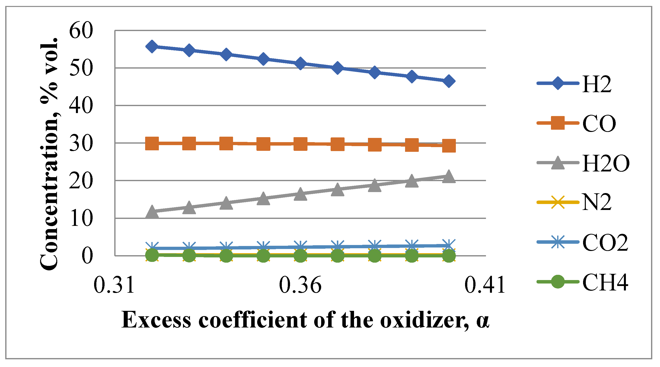
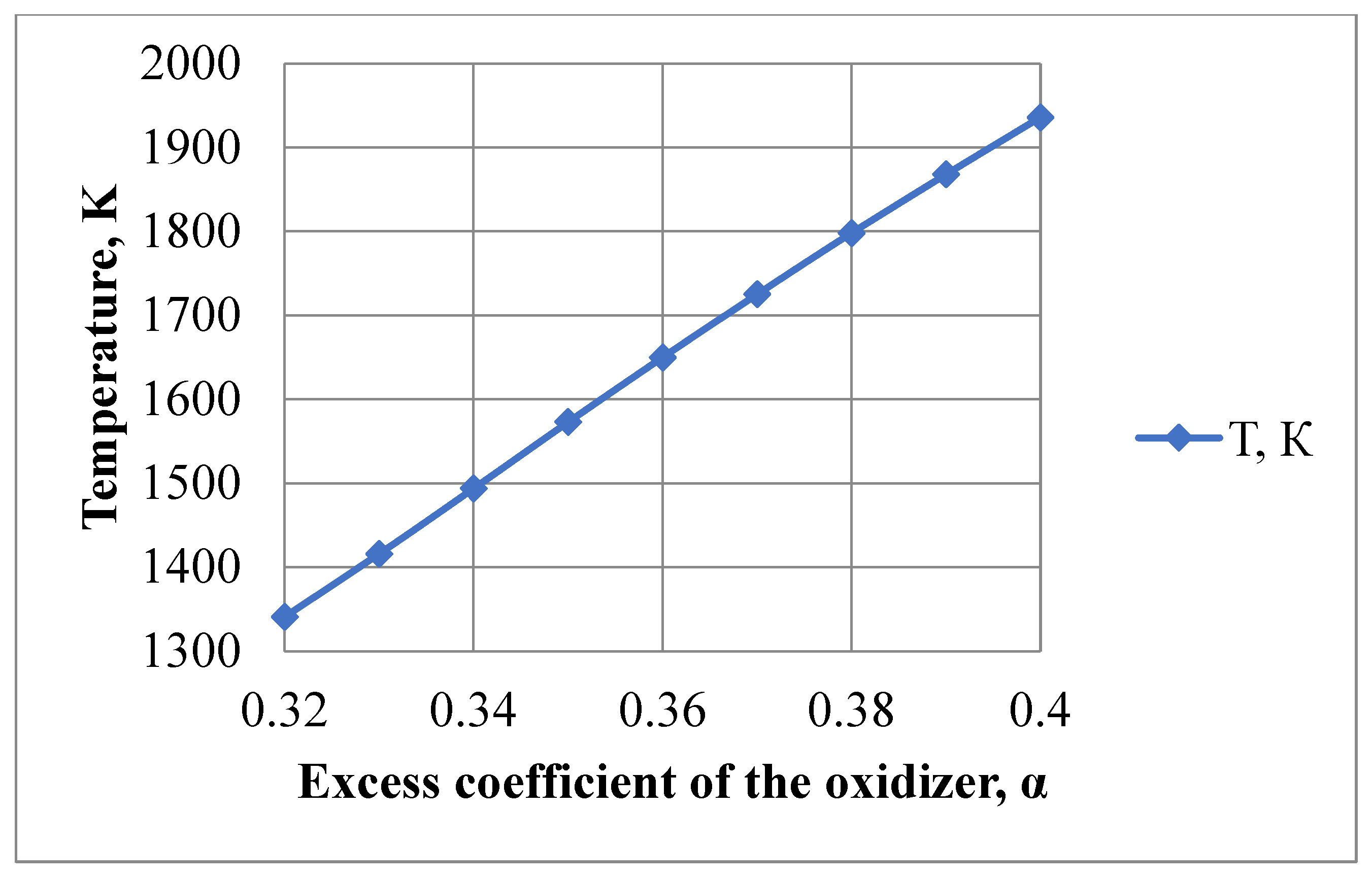
2.1. Thermodynamics of Natural Gas POX

The purpose of thermodynamic calculations is to study the effect of the POX mode parameters on the balance composition of the combustion products of natural gas. The justification of the mode of obtaining a hydrogen-containing gas that provides the maximum concentration of hydrogen with the minimum formation of the condensed phase (soot and tar) then follows. At first, it is necessary to assess the rational range of the main parameter variation in the POX mode—the oxidizer excess coefficient:
α = mox/(mrKm0)
where mr is the mass yield of raw materials (natural gas), mox is the mass yield of oxidizer, and Km0 is the mass stoichiometric ratio of components, determined according to the reference data (for example, for a pair of technical oxygen–methane Km0 = 4.0).
There are numerous works devoted to the study of the α influence on the composition of the gas obtained as a result of the partial oxidation of hydrocarbon raw materials [27,28,29]. Figure 1 and Figure 2 show some calculation results for the following conditions: raw materials—humidified natural gas (CH4—97.57 % vol., C2H6—1 % vol., C3H8—0.37 % vol., C4H10—0.15 % vol., N2—0.84 % vol., CO2—0.07 % vol.), humidity ratio of raw materials is 15% mass of water vapor to mass of natural gas; oxidizer is oxygen; pressure in the synthesis gas generator combustion chamber is 6.0 MPa; initial temperature of oxidizer heating is 170 °C, natural gas—450 °C [30,31,32].
The results of the calculations and analysis of the works allow formulating recommendations for the choice of rational POX modes [27,28,29]. It is advised to carry out POX of methane with oxygen at α = 0.33–0.35. Lower values of α may cause the appearance of a condensed phase in the combustion products, and higher values may lead to a decrease in the concentration of hydrogen [30,31,32].
The optimal degree of natural gas humidification is in the range of 15–20% mass of water vapor in relation to the mass of the natural gas. This is one of the most important measures for the prevention of soot formation, and leads to an insignificant—by 3–5%—increase in the H2/CO ratio due to side reaction of homogeneous steam reforming of methane in the combustion chamber.
Pressure in the combustion chamber has no significant effect on the balance ratios of POX products. It is advisable to choose it in the range of 2.5–3.5 MPa for optimal operation of catalysts for CO steam reforming. This process is used to increase the concentration of hydrogen in the gas at the SGG outlet, as well as to ensure the required pressure drop in the gas purification system at the outlet of the unit.
Higher temperature of raw materials in POX reaction facilitates ignition, and ensures stable combustion and an increased reaction rate. Initial temperature of the raw materials is chosen regarding the conditions of self-ignition for methane–oxygen mixtures (for oxygen, not higher than 170 °C; for natural gas, up to 500 °C), as well as the possible condensation of water vapor, depending on their partial pressure in a hydrogen-containing gas.
A feature in the calculations of thermodynamic processes in the SGG is the need to assess the influence of the chemically treated water supply to the evaporation chamber on the parameters and composition of the gas at the SGG outlet. It follows from the calculations that an increase for water proportionally decreases the gas temperature, while the content of water vapor in the gas increases and the concentration of H2 and CO decreases. An increase in the H2/CO ratio >1.9 due to the homogeneous steam conversion of unreacted methane in the combustion chamber and the non-catalytic CO steam conversion is also observed.

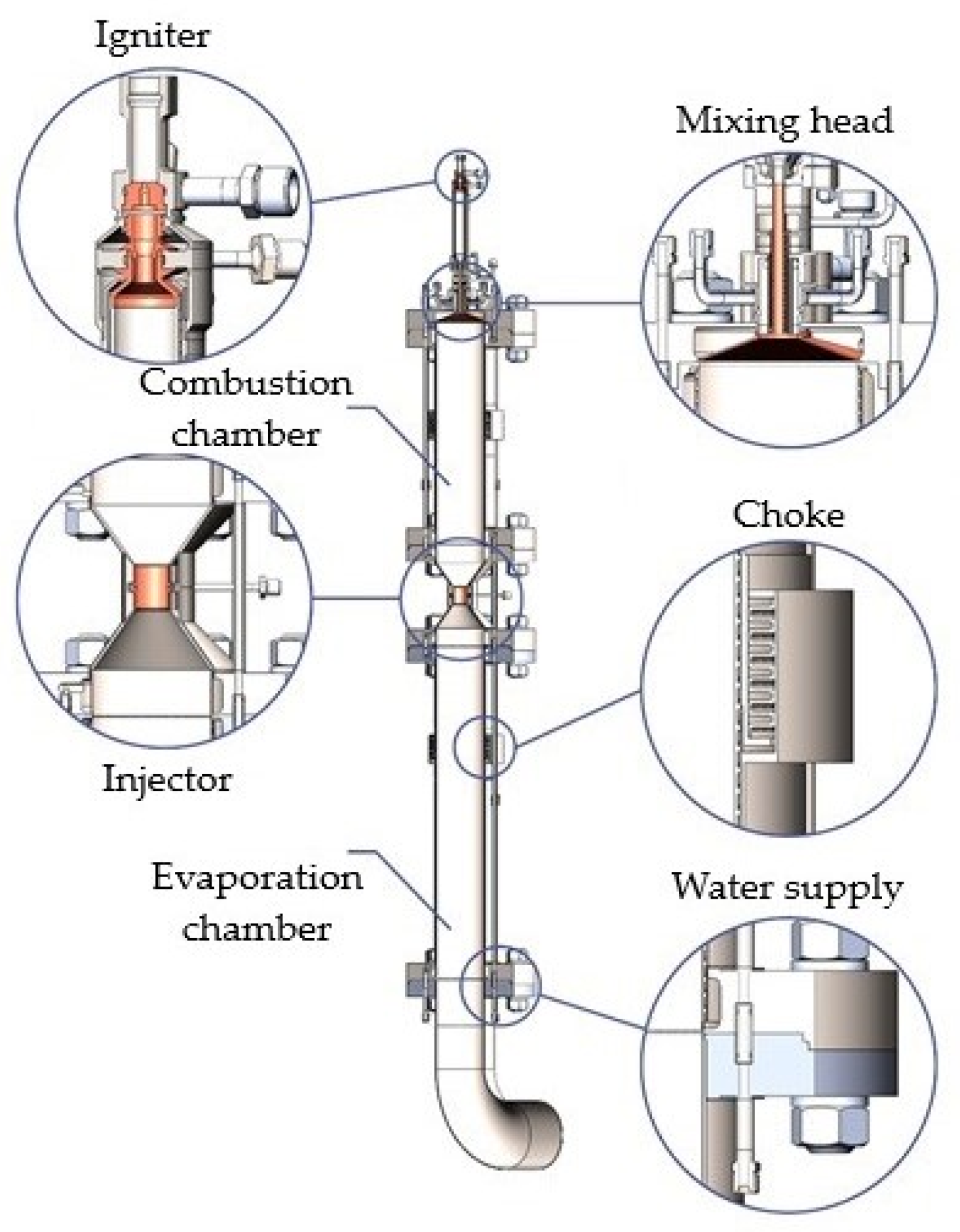
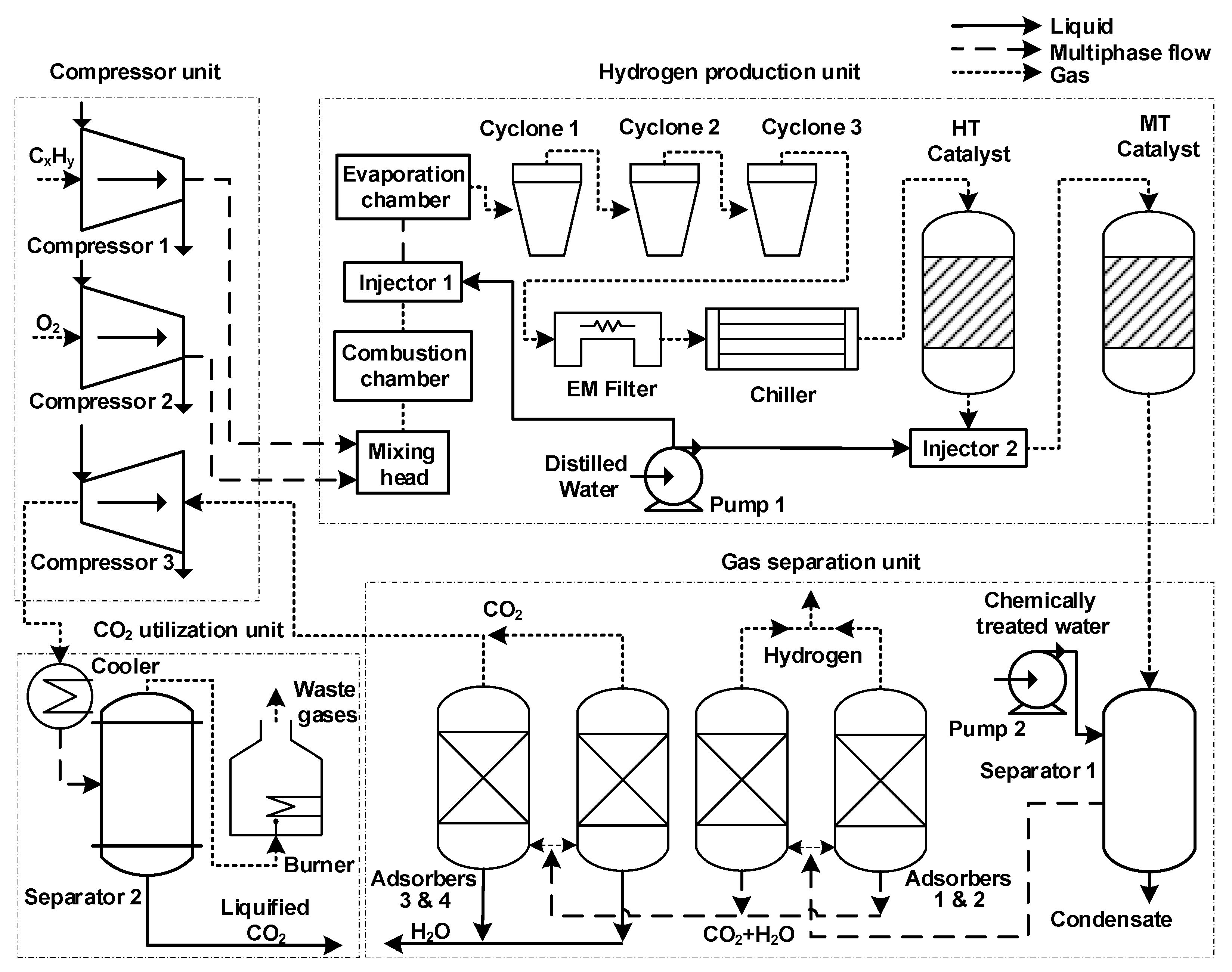
2.2. Design of Gas Generator

The SGG is the main unit of the structure for the production of hydrogen-containing gas. Technical characteristics of the SGG are given in Table 1.
An SGG (Figure 3) is constructed as a pipe in a pipe; chemically treated water passes through its annular space.
An SGG consists of the following main units: an igniter, a mixing head, a combustion chamber, an injector, and an evaporation chamber [26]. The most complex element of the SGG is the mixing head. It influences the conditions of mixture formation when the components of the reaction are supplied to the combustion chamber. Next, the mixing head determines the SGG characteristics such as flow rate, unit efficiency, initial degree of components’ conversion, reliability, unit dimensions, and so on.

3. Results

The technological scheme of the developed technology for production of “blue” hydrogen is presented in Figure 4. Installation consisted of four parts: hydrogen production unit, gas separation unit, compressor unit, and CO2 utilization unit.
The proposed hydrogen production technology is conducted in two stages. At the first stage of the process, partial oxidation of natural gas is carried out with a lack of oxygen. This process takes place at high velocities. Duration of the basic reaction in the combustion chamber does not exceed one millisecond at pressures of 2.5–3.5 MPa and temperatures of 1400–1600 °C [26,33,34]. As a result, a hydrogen-containing gas containing 40–42 % vol. hydrogen, 21–23 % vol. carbon monoxide, 33–35 % vol. water vapor, up to 3 % vol. carbon dioxide, and traces of methane and soot, is formed at the SGG outlet.
Gas at the SGG outlet is purified from the solid phase and then it is cooled and fed to the catalysis unit. Steam catalytic conversion of CO is carried out in the second stage of the process. It proceeds in the presence of catalysts by the exothermic reaction CO + H2O = CO2 + H2. It was proposed to carry out the conversion of CO in two stages [35]: first, at high-temperature (HT), and then at medium-temperature (MT), in the presence of Cu–Zn–cement-containing catalysts. Nominal thermodynamic parameters are: pressure 2.5–3.5 MPa, with temperature 250–550 °C for HT with content of zinc oxide increased up to 40% mass, and 180–350 °C for MT with content of copper oxide increased up to 48% mass. The lower limit of the conversion temperature is limited by the condensation temperature of water vapor.
Table 2 and Table 3 show the results of the catalysts’ tests in the high-temperature and medium-temperature conversion ranges [35].
HT catalyst is insensitive to droplet moisture, has high thermal stability and can operate in a wide temperature range up to 600 °C. MT catalyst has high and stable catalytic activity in the operating temperature range of 200–400 °C. Recommended volumetric conversion rates are 4000–6000 h–1 [35]. Use of a single catalytic composition simplifies the activation and passivation technology of catalysts, and the use of HT catalyst with a higher zinc content gives it an additional function of a chemisorbant of sulfur-containing components. The obtained mixture is directed from the catalysis unit to the separator for condensate separation. The working process in the SGG is schematically shown in Figure 5.
Dried gas goes from the separator to adsorbers for removal of hydrogen and subsequent separation of carbon dioxide from water. Separated CO2 is compressed and cooled to complete liquefaction for further storage, transport, and utilization.
A calculation example of a change in the balance composition of gas in the main apparatus of the device is given in Table 4. Partial oxidation of the reduced composition of natural gas by oxygen is done with these parameters: α = 0.35, combustion chamber pressure is 3.5 MPa, gas mixture initial temperature is 300 °C, humidification degree is 15% mass from the natural gas mass, mass flow rate of water injection into the evaporation chamber is 40% in relation to the mass flow rate of gas at the outlet of the SGG combustion chamber.

4. Discussion

4.1. Theoretical Contributions

The process of mixture formation when introducing raw materials and an oxidizer has the following features. Uniformity of the distribution for the rich mixture’s components (with an excess of raw materials relative to stoichiometry) is of particular importance. Zones with relatively low and high gas temperatures are formed if there is a considerable uneven distribution of reaction components near the mixing head. Such conditions may cause the formation of solid particles, specifically on the boundary of these zones. Furthermore, soot particles are formed in the zones of reverse currents with lower temperatures. That is why presence of reverse gas currents near the mixing head should be minimized. Next, the gas is usually present in reverse currents for a longer time than it is in the chamber, which may also cause the formation of soot. Creation of reverse gas currents with relatively high relation of components can minimize this effect.

4.2. Practical Implications

Several experimental installations were created to assess the calculated characteristics of SGGs. A pilot demonstration unit for the production of hydrogen with a capacity of 300 nm3/h (PDU-300) was manufactured according to the patent [33] by order of PJSC “Cryogenmash” [25]. The main technological module of PDU-300 was built into a standard 20-foot container (Figure 6). It contained the SGG with devices of component introduction (methane, oxygen, chemically treated water); a gas purification unit; a block of converters with catalysts (iron–chromium STK-2 and low-temperature K-CO, which contains oxides of copper, zinc, and aluminum); a refrigerator-separator; a pump block; sampling devices; and a control system with an operator’s workstation located in a separate box. Preliminary treatment of raw materials—heating and humidification of methane—was not carried out.
Test results of PDU-300 confirmed the characteristics of the SGG and the calculated material balance of the unit. Thus, at α ≈ 0.34, the hydrogen concentration, after the catalysis unit, in terms of dry hydrogen-containing gas, was 68–70 % vol., with hydrogen dioxide at 20–22 % vol. Methane residues and traces of carbon monoxide were also observed, as well as nitrogen and argon from purging [25].

4.3. Future Avenues

The conducted tests revealed directions for further improvement of the developed technology. It is necessary to reduce heat losses and to pre-treat the hydrocarbon raw materials (perform heating and humidification) in order to reduce soot formation. It is also feasible to change the design of the catalysis unit and make a transition to a single catalytic composition with a wider operating temperature range.

5. Conclusions

The purpose of the article was to review current technologies of hydrogen production and propose a technology for its small-scaled generation that would be environmentally friendly. The developed installation for production of low-carbon (“blue”) hydrogen can be used for these needs. The acquired results show that it is possible to implement the proposed technology to produce hydrogen when the supply of the hydrocarbon gas is low, e.g., at oil and gas fields. In this regard, the technical characteristics of developed gas generators make it possible to create transportable modules for the production of hydrogen-containing gas with a unit capacity of up to 10,000 nm3/h.
Features of hydrogen production using the POX technology, which is quite efficient for hydrocarbon gas, in original synthesis gas generators were presented in the paper. It described the technique and technological structure for the production of hydrogen-containing gas, and gave calculations on the material and energy balance of the unit. The following parameters were experimentally achieved on the methane–oxygen components at the outlet of the catalysis unit in terms of dry gas: hydrogen concentration 68–70 % vol., ratio of syngas components H2/CO = 1.9–2.1.
In order to increase the energy-efficiency of the system, by-product oxygen from the production of “green” hydrogen can be used as an oxidizing agent. The carbon footprint of the hydrogen production can be lowered by subsequent removing and liquefying of CO2, which can be accumulated or utilized directly. Such combination of technologies may increase the profitability of hydrogen production.
Future research with regard to the developed technology is associated with the prevention of soot formation by using the heat of a hydrogen-containing gas to heat the components and generate steam to humidify the raw materials. Transition to a single composition of Cu–Zn–cement-containing catalysts is also considered. The application of petroleum gas with varying composition as a raw material for the production of hydrogen is of particular interest.

Author Contributions

Conceptualization, Y.Z. and A.K.; Formal analysis, G.B.; Funding acquisition, V.M.; Investigation, Y.Z. and A.K.; Methodology, V.M. and G.B.; Project administration, A.K. and V.M.; Resources, G.B. and A.K.; Software, V.M. and G.B.; Validation, Y.Z. and A.K.; Visualization, V.M. and G.B.; Writing—original draft, A.K.; Writing—review and editing, V.M. All authors have read and agreed to the published version of the manuscript.

Funding

Research was carried out with financial support by subsidy for the implementation of the state task in the field of scientific activity in 2021 No. FSRW-2020-0014.

Data Availability Statement

The data presented in this study are available on request from the corresponding author. The data are not publicly available due to its storage in private networks.

Acknowledgments

Authors are grateful to A.A. Levikhin; A.V. Moroz; engineers A.A. Galajun, M.V. Kleshchenko, V.V. Pobelyansky and other colleagues who took part in the design and testing of the PDU-300, as well as V.N. Efremov for discussion of technological solutions.

Conflicts of Interest

The authors declare no conflict of interest.

References

  1. Litvinenko, V.S.; Tsvetkov, P.S.; Dvoynikov, M.V.; Buslaev, G.V. Barriers to implementation of hydrogen initiatives in the context of global energy sustainable development. J. Min. Inst. 2020, 244, 421. [Google Scholar] [CrossRef]
  2. Dawood, F.; Anda, M.; Shafiullah, G.M. Hydrogen production for energy: An overview. Int. J. Hydrogen Energy 2020, 45, 3847–3869. [Google Scholar] [CrossRef]
  3. Tarasov, B.P.; Lototsky, M.V.; Yartys, V.A. The Problem of hydrogen storage and prospects for using hydrides for hydrogen storage. Russ. Chem. J. 2006, 6, 34–48. [Google Scholar]
  4. Rusman, N.A.A.; Dahari, M.A. Review on the current progress of metal hydrides material for solid-state hydrogen storage applications. Int. J. Hydrogen Energy 2016, 41, 12108–12126. [Google Scholar] [CrossRef]
  5. Bellosta von Colbe, J.; Ares, J.R.; Barale, J.; Baricco, M.; Buckley, C.; Capurso, G.; Gallandat, N.; Grant, D.M.; Guzik, M.N.; Jacob, I.; et al. Application of hydrides in hydrogen storage and compression: Achievements, outlook and perspectives. Int. J. Hydrogen Energy 2019, 44, 7780–7808. [Google Scholar] [CrossRef]
  6. Dvoynikov, M.; Buslaev, G.; Kunshin, A.; Sidorov, D.; Kraslawski, A.; Budovskaya, M. New concepts of hydrogen production and storage in Arctic region. Resources 2021, 10, 3. [Google Scholar] [CrossRef]
  7. Ilinova, A.; Chanysheva, A. Algorithm for assessing the prospects of offshore oil and gas projects in the Arctic. Energy Rep. 2020, 6, 504–509. [Google Scholar] [CrossRef]
  8. Tsvetkov, P.S.; Fedoseev, S.V. Analysis of project organization specifics in small-scale LNG production. J. Min. Inst. 2021, 246, 678–686. [Google Scholar] [CrossRef]
  9. Ostadi, M.; Paso, K.G.; Rodriguez-Fabia, S.; Oi, L.E.; Manenti, F.; Hillestad, M. Process Integration of Green Hydrogen: Decarbonization of Chemical Industries. Energies 2020, 13, 4859. [Google Scholar] [CrossRef]
  10. Parkinson, B.; Tabatabaei, M.; Upham, D.C.; Ballinger, B.; Greig, C.; Smart, S.; McFarland, E. Hydrogen production using methane: Techno economics of decarbonizing fuels and chemicals. Int. J. Hydrogen Energy 2017, 43, 2540–2555. [Google Scholar] [CrossRef]
  11. Abbas, H.F.; Wan Daud, W.M.A. Hydrogen production by methane decomposition: A review. Int. J. Hydrogen Energy 2010, 35, 1160–1190. [Google Scholar] [CrossRef]
  12. Dal, P.Y.; Christensen, T.S.; Winter-Madsen, S. Technology of autothermal reforming for modern large-scale methanol plants. In Proceedings of the International Conference “Nitrogen and Syngas—2014”, Paris, France, 24–27 February 2014; p. 14. [Google Scholar]
  13. Chen, W.H.; Chen, C.Y. Water gas shift reaction for hydrogen production and carbon dioxide capture: A review. Appl. Energy 2020, 258, 114078. [Google Scholar] [CrossRef]
  14. Bazhin, V.Y.; Trushnikov, V.E.; Suslov, A.P. Simulation of partial oxidation of natural gas in a resource-saving reactor mixer. IOP Conf. Ser. Mater. Sci. Eng. 2020, 862, 032076. [Google Scholar] [CrossRef]
  15. Liu, K.; Song, C.; Subraman, V. (Eds.) Hydrogen and Syngas Production and Purification Technologies; John Wiley & Sons: Hoboken, NJ, USA, 2010; p. 564. [Google Scholar]
  16. Indarto, A.; Palguandi, J. (Eds.) Syngas Production, Application and Environmental Impact; Nova Science Publishers: New York, NY, USA, 2013; p. 365. [Google Scholar]
  17. Makhlin, V.A.; Tsetseruk, Y.R. Modern technologies for producing synthesis gas from natural and associated gas. Chem. Ind. Today 2010, 3, 6–17. [Google Scholar]
  18. Pena, M.; Gomez, J.; Fierro, J.L.G. New catalytic routes for syngas and hydrogen production. Appl. Catal. A Gen. 1996, 144, 7–57. [Google Scholar] [CrossRef]
  19. York, A.P.E.; Xiao, T.; Green, M.L.H. Brief overview of the partial oxidation of methane to synthesis gas. Top. Catal. 2003, 22, 345–358. [Google Scholar] [CrossRef]
  20. Arutyunov, V.S.; Savchenko, V.I.; Sedov, I.V. New concepts for the development of low-tonnage gas chemistry. Oil Gas Chem. 2014, 4, 19–23. [Google Scholar]
  21. Bilera, I.V.; Borisov, A.A.; Borunova, A.B.; Kolbanovsky, Y.A.; Korolev, Y.M.; Rossikhin, Y.V.; Troshin, I.V. Formation of highly dispersed soot during synthesis gas production under methane combustion conditions. Gas Chem. 2010, 3, 72–78. [Google Scholar]
  22. Kato, T.; Kubota, M.; Kobayashi, N.; Suzuoki, Y. Effective utilization of by-product oxygen from electrolysis hydrogen production. Energy 2005, 30, 2580–2595. [Google Scholar] [CrossRef]
  23. Kulchakovsky, P.I.; Mitberg, E.B.; Ermolaev, I.S.; Ermolaev, V.S.; Solomonik, I.G.; Mordkovich, V.Z. Investigation of the process of non-catalytic high-temperature partial oxidation of methane to obtain synthesis gas. Thermal Process. Technol. 2016, 8, 117–125. [Google Scholar]
  24. Lugvishchuk, D.S.; Kulchakovsky, P.I.; Mitberg, E.B.; Mordkovich, V.Z. Soot Formation in the Methane Partial Oxidation Process under Conditions of Partial Saturation with Water Vapor. Petroleum Chem. 2018, 58, 427–433. [Google Scholar] [CrossRef]
  25. Zagashvili, Y.V. Technology of hydrogen production using small-sized transportable plants based on high-temperature synthesis gas generators. Probl. Mater. Sci. 2017, 2, 92–109. [Google Scholar]
  26. Zagashvili, Y.V.; Levikhin, A.A.; Kuzmin, A.M. Basics of designing three-component synthesis gas generators. Oil Gas Chem. 2017, 4, 9–16. [Google Scholar]
  27. Sister, V.G.; Borisov, A.A.; Troshin, K.Y. Partial oxidation of methane in combustion and autoignition modes. Chem. Phys. 2006, 25, 61–68. [Google Scholar]
  28. Aniskevich, Y.V.; Krasnik, V.V.; Filimonov, Y.N. Choice of operating parameters of the process of partial gas-phase oxidation of methane with atmospheric oxygen in order to obtain synthesis gas of the required composition. J. Appl. Chem. 2009, 82, 1335–1341. [Google Scholar]
  29. Brüggemann, P.; Seifert, P.; Meyer, B.; Müller-Hagedorn, M. Influence of Temperature and Pressure on the Non-Catalytic Partial Oxidation of Natural Gas. Chem. Prod. Process Model. 2010, 5, 1–24. [Google Scholar] [CrossRef]
  30. Zhou, X.; Chen, C.; Wang, F. Multi-dimensional modeling of non-catalytic partial oxidation of natural gas in a high pressure reformer. Int. J. Hydrogen Energy. 2010, 35, 1620–1629. [Google Scholar] [CrossRef]
  31. Jaber, O.; Naterer, G.F.; Dincer, I. Natural gas usage as a heat source for integrated SMR and thermochemical hydrogen production technologies. Int. J. Hydrogen Energy 2010, 35, 8569–8579. [Google Scholar] [CrossRef]
  32. Xu, Y.; Dai, Z.; Li, C.; Li, X.; Zhou, Z.; Yu, G.; Wang, F. Numerical simulation of natural gas non-catalytic partial oxidation reformer. Int. J. Hydrogen Energy 2014, 39, 9149–9157. [Google Scholar] [CrossRef]
  33. Filimonov, Y.N.; Zagashvili, Y.V.; Savchenko, G.B.; Levikhin, A.A. Method for Producing Hydrogen from Hydrocarbon Raw Materials. Patent No. 2561077, 20 August 2015. [Google Scholar]
  34. Zagashvili, Y.V.; Kuzmin, A.M. Low-Tonnage Hydrogen Production Unit. Patent No. 184920, 22 August 2021. [Google Scholar]
  35. Zagashvili, Y.V.; Efremov, V.N.; Golosman, E.Z.; Kuzmin, A.M. Cu-Zn-cement-containing catalyst for two-stage steam reforming of carbon monoxide in hydrogen plants. In Proceedings of the Scientific Conference “Actual Problems of Theory and Practice of Heterogeneous Catalysts and Adsorbents”, Ivanovo, Russia, 26–30 June 2018; Volume 2, pp. 117–118. [Google Scholar]
Figure 1. Dependence of the components’ concentration in the hydrogen-containing gas on the excess coefficient of the oxidizer.
Energies 14 05194 g001
Figure 2. Dependence of gas temperature on the excess coefficient of the oxidizer.
Energies 14 05194 g002
Figure 3. General scheme of synthesis gas generator.
Energies 14 05194 g003
Figure 4. Technological scheme of “blue” hydrogen production.
Energies 14 05194 g004
Figure 5. Scheme of the working process in the SGG.
Energies 14 05194 g005
Figure 6. Technological module of PDU-300.
Energies 14 05194 g006
Table 1. Technical characteristics of the synthesis gas generator.
ParameterValues
Syngas production rate200–10,000 nm3/h
Regulation range+/−15%
Component feed pressure, MPa0.2–8.0
Temperature in combustion chamber, K1300–3500
SGG inner diameter, m0.1–0.5
SGG length, m0.5–5.0
Oxidizer typeoxygen, air, enriched air
Aggregation state of raw materialsgas, liquid
SGG mass, kg30–300
Table 2. CO conversion degree depending on gas temperature with HT catalyst.
HT Catalyst Composition, % MassTemperature, °C
300400550
CO Conversion Degree, %
CuO—27.0 ± 4.0; ZnO—40.0 ± 4,
aluminum calcium cement
0.9600.9300.840
Table 3. CO conversion degree depending on gas temperature with MT catalyst.
MT Catalyst Composition, % MassTemperature, °C
200300350
CO Conversion Degree, %
CuO—48.0 ± 3.0; ZnO—22.5 ± 2.5,
aluminum calcium cement
0.9800.9700.960
Table 4. CO conversion degree depending on gas temperature with HT catalyst.
StreamComposition of Gas Mixture, % vol.T, °CP, MPa
H2COCO2CH4H2ON2
Outlet of the combustion chamber52.429.82.10.015.30.215703.5
Outlet of the evaporation chamber40.821.82.60.833.80.29003.3
Inlet of the HT unit40.821.82.60.833.80.23003.3
Outlet of the HT unit61.01.622.80.913.50.24953.2
Inlet of the MT unit58.31.521.80.917.30.22503.2
Outlet of the MT unit59.70.123.20.915.90.22653.1
Outlet of the separator70.80.127.51.00.40.2403
Outlet of adsorbers 1 and 20.020.394.23.41.40.773
Outlet of adsorbers 3 and 40.020.3595.53.4700.771.7
Outlet of the compressor 30.020.3595.53.4700.771.7
Outlet of the separator 200100023.11.7
Publisher’s Note: MDPI stays neutral with regard to jurisdictional claims in published maps and institutional affiliations.

