
Analysis of the Parameters of the Two-Sections Hot Side Heat Exchanger of the Module with Thermoelectric Generators


Abstract
:1. Introduction
2. Materials and Methods
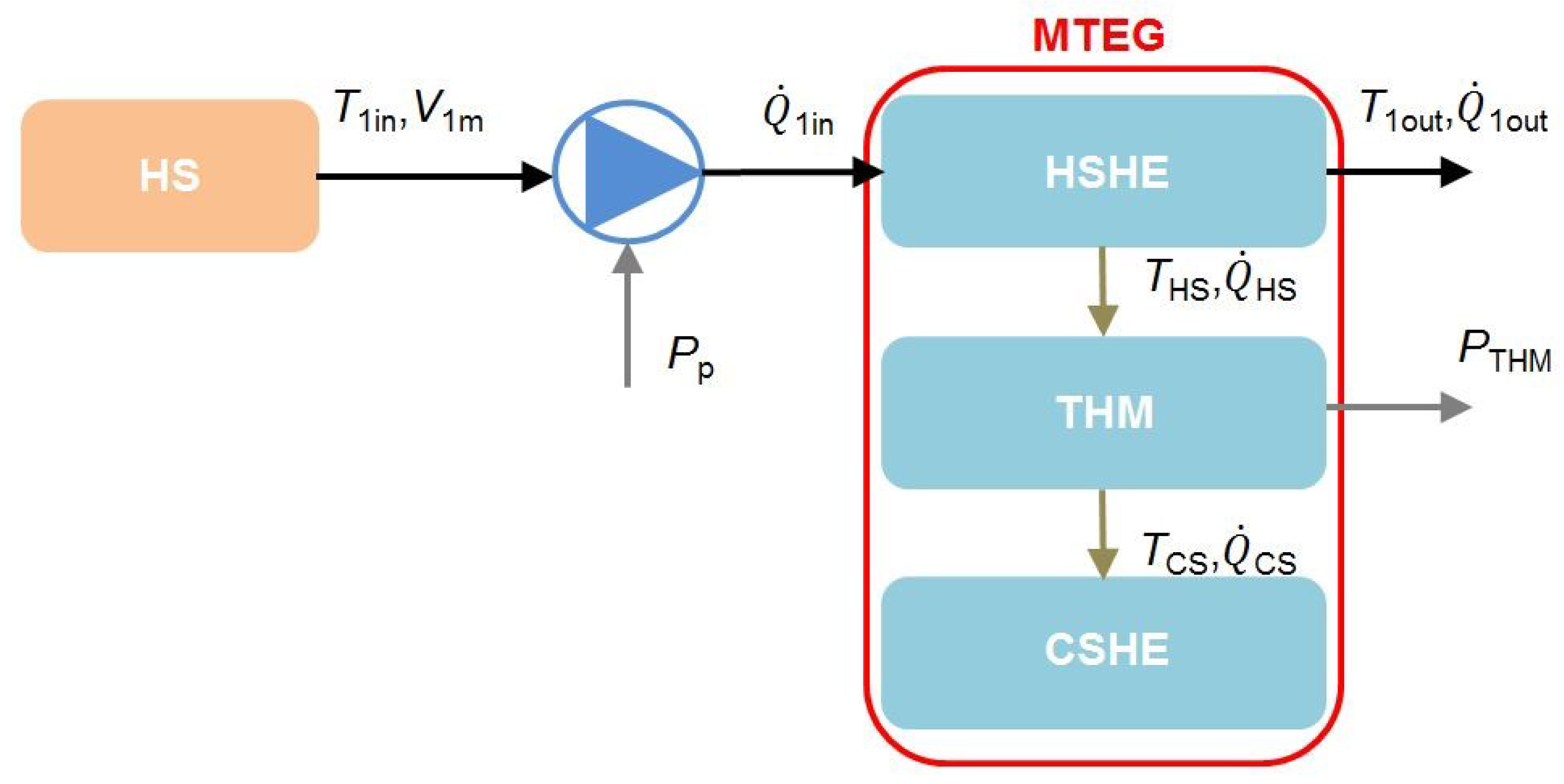
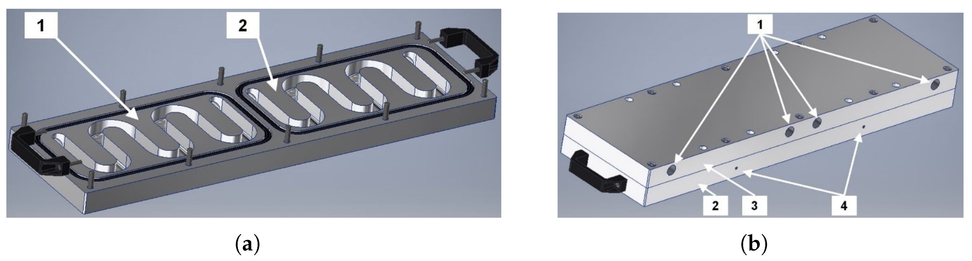
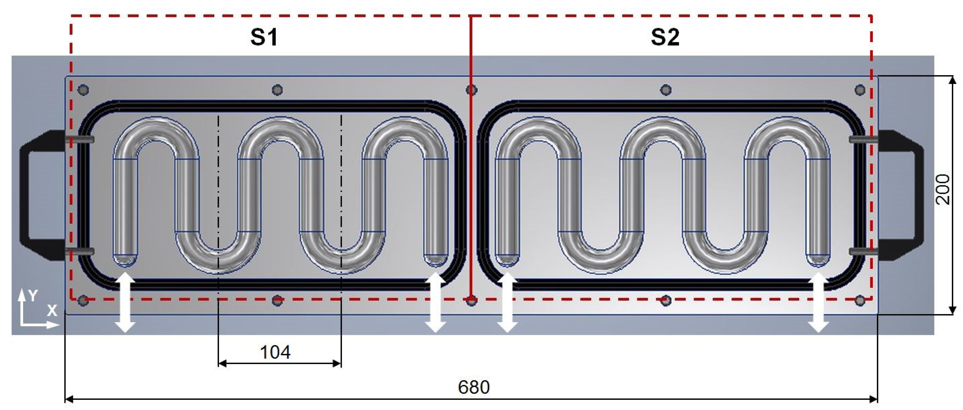
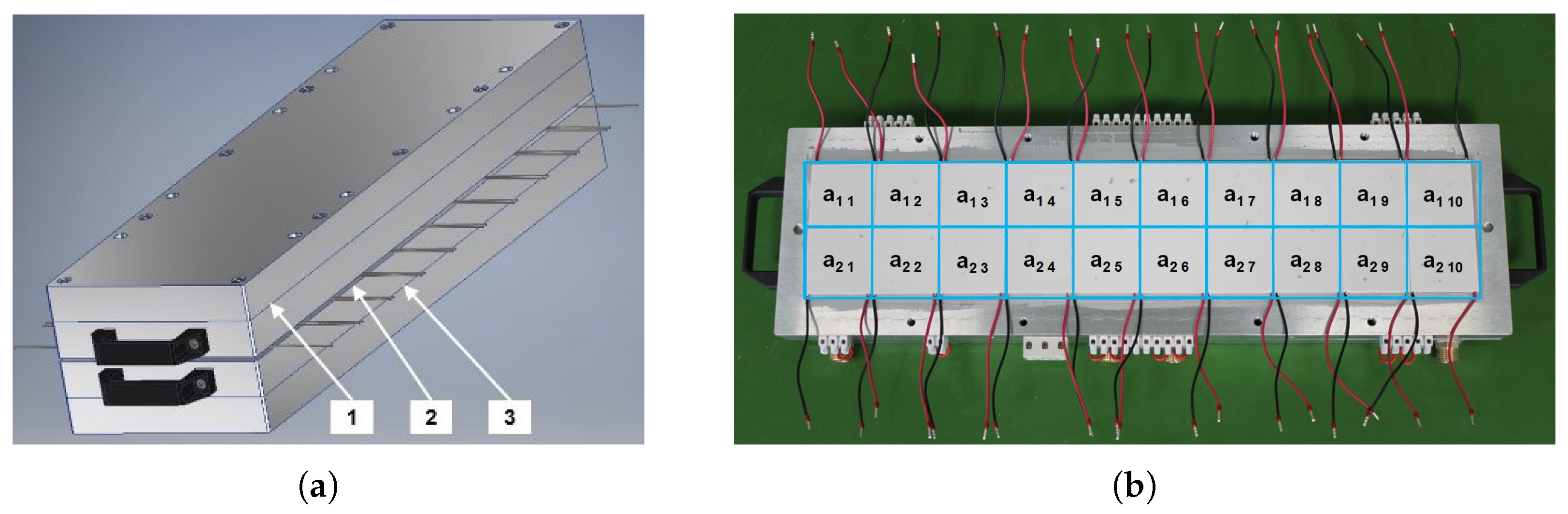
2.1. The Construction of the TEG Module
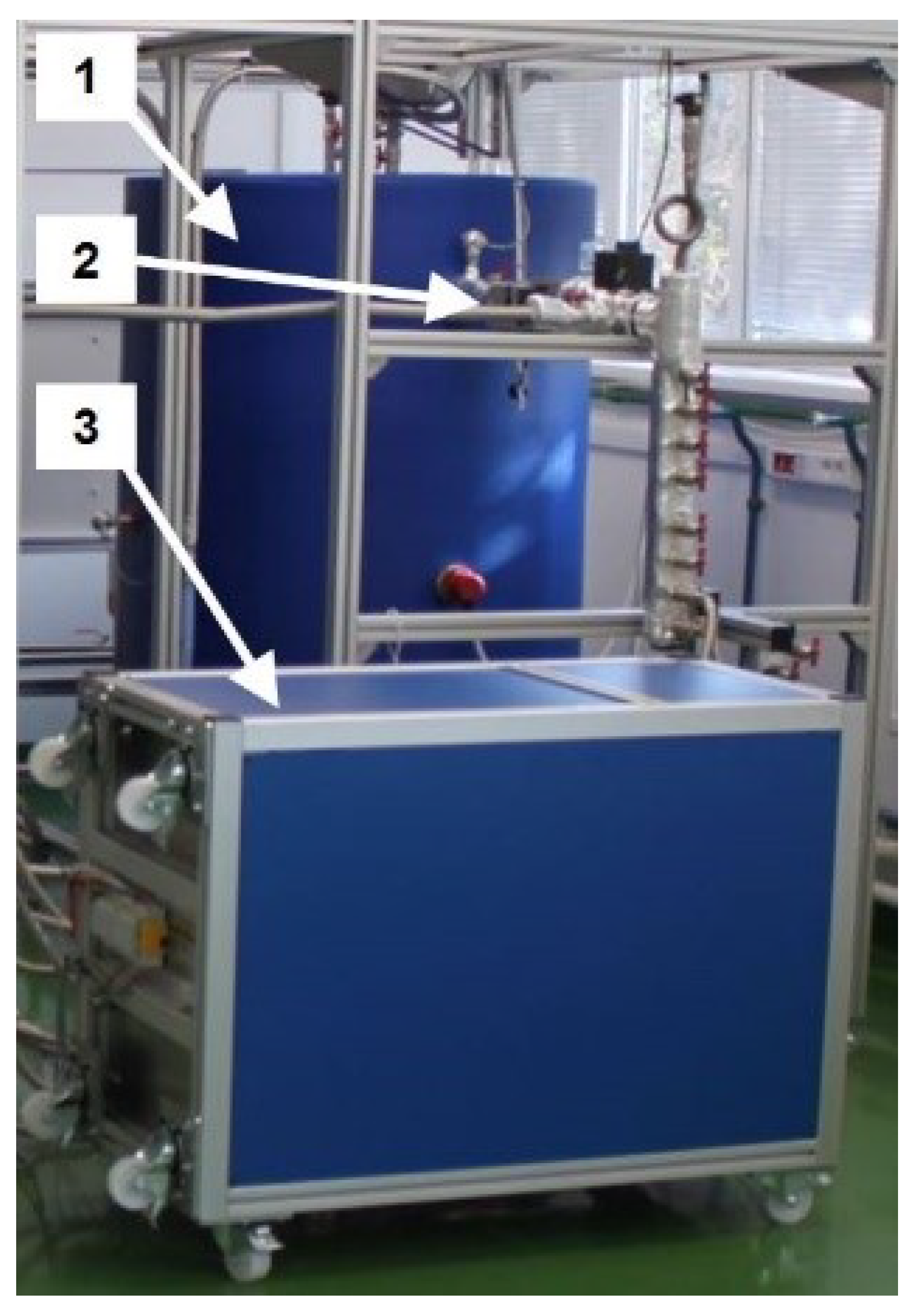
2.2. Description of the Laboratory Stand
3. Results
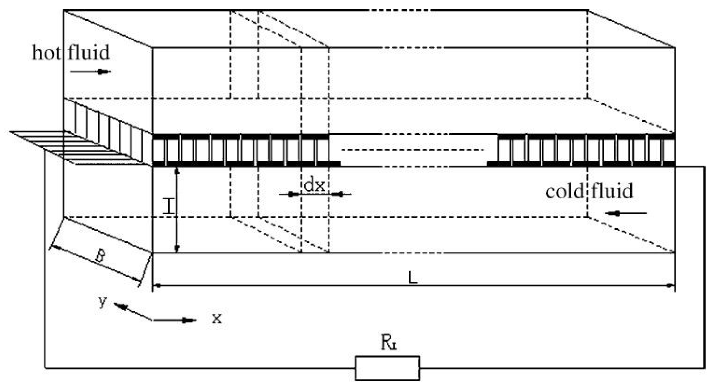
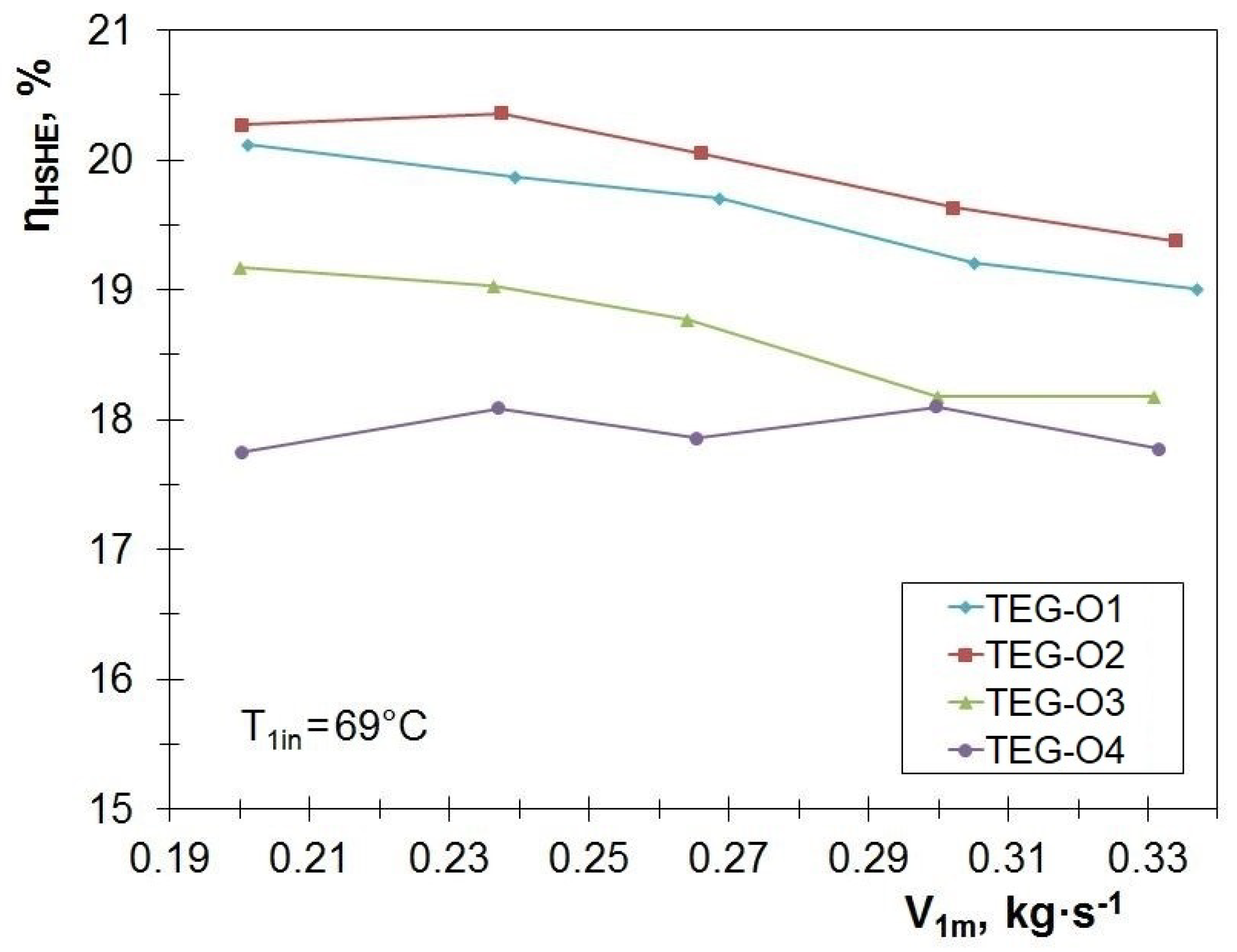
3.1. Effectiveness of the Heat Exchanger
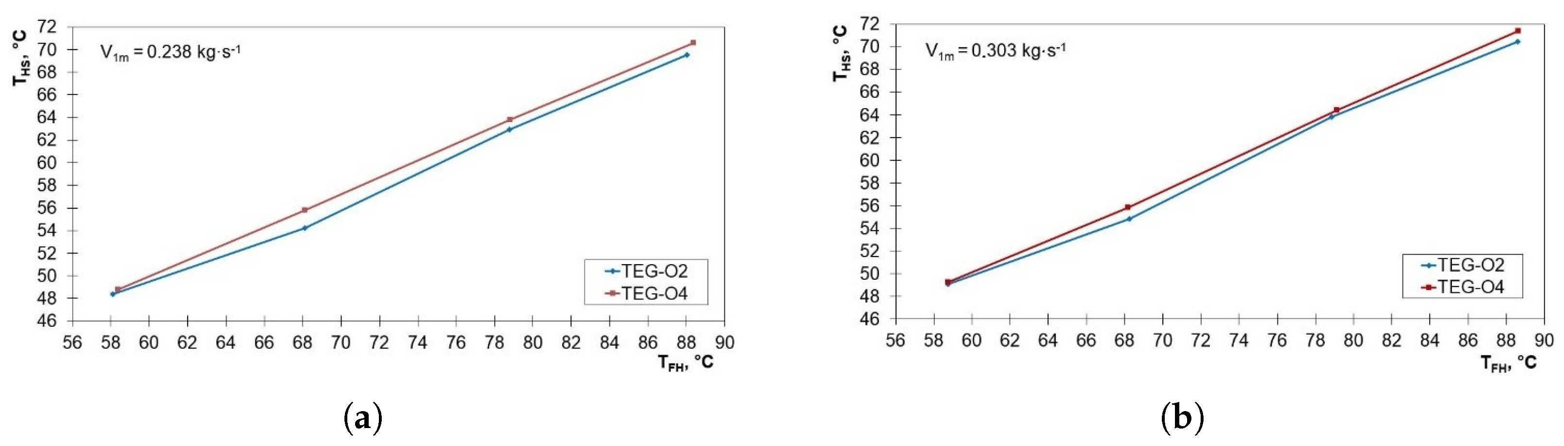
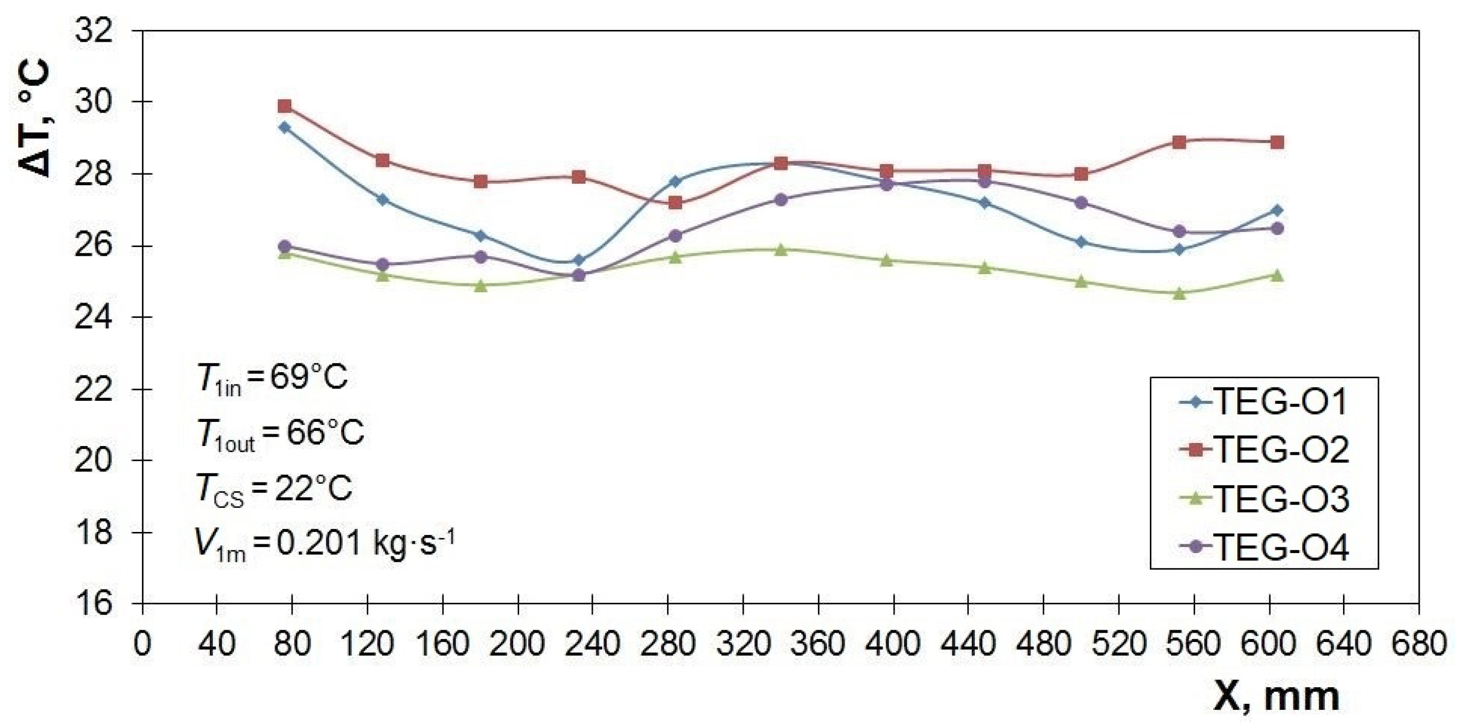
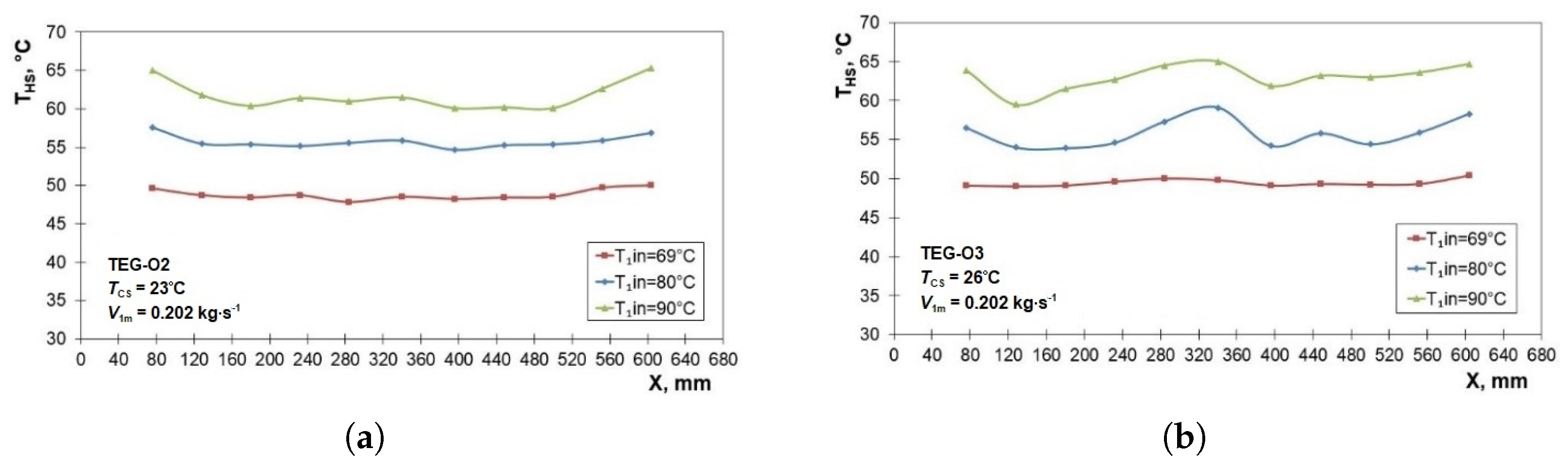
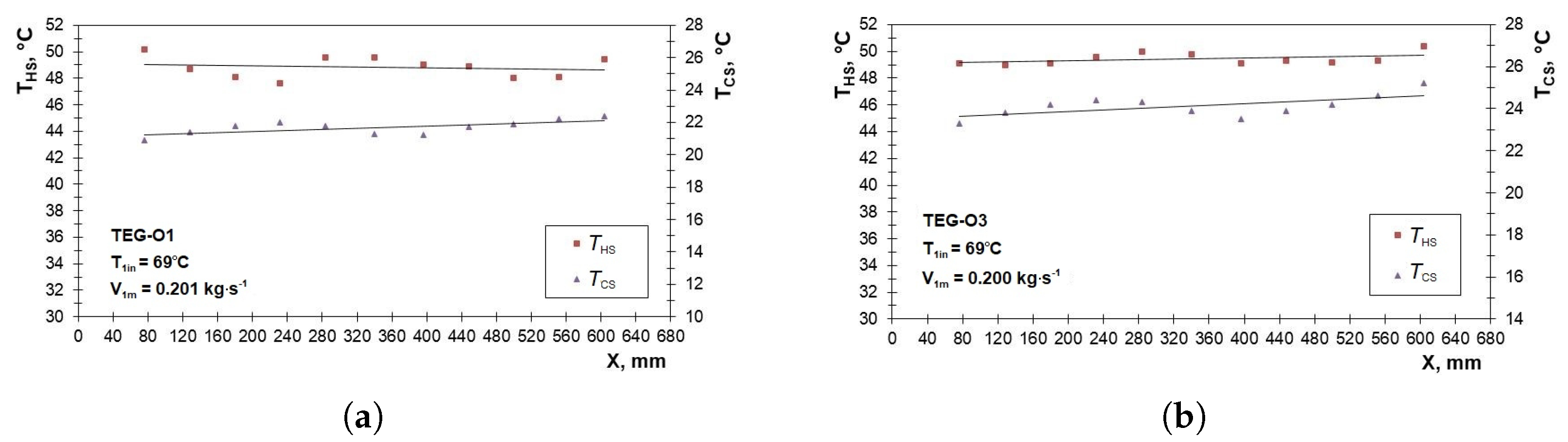
3.2. Distribution of Parameters along the HSHE
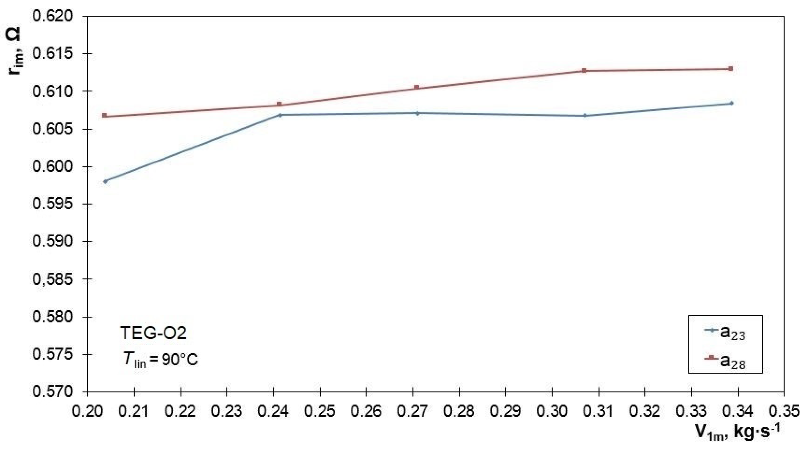
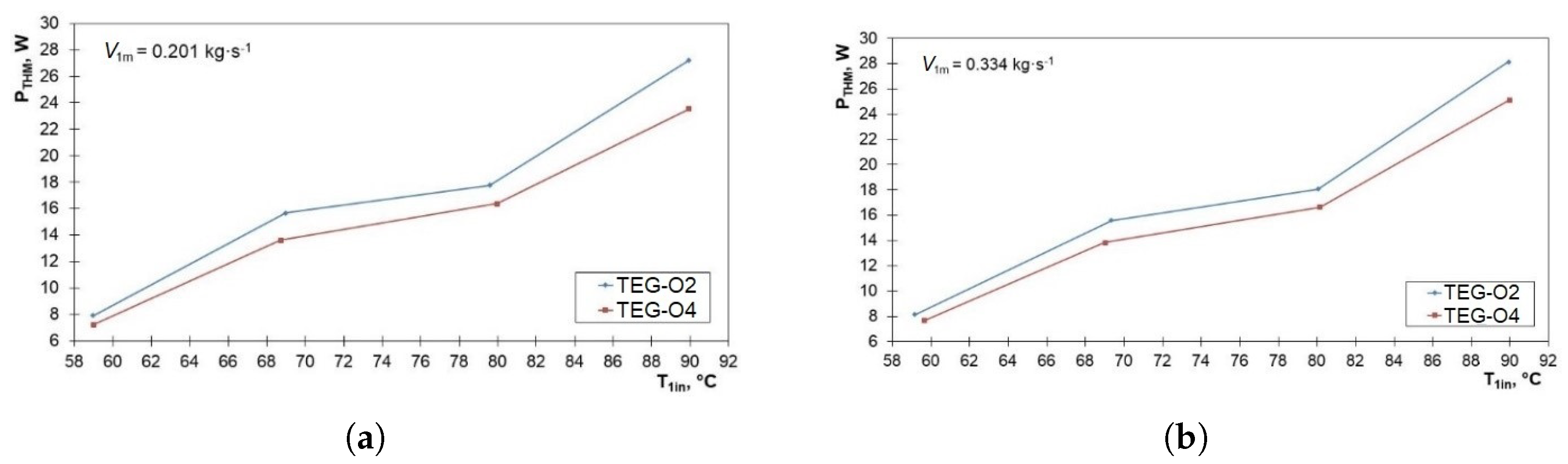
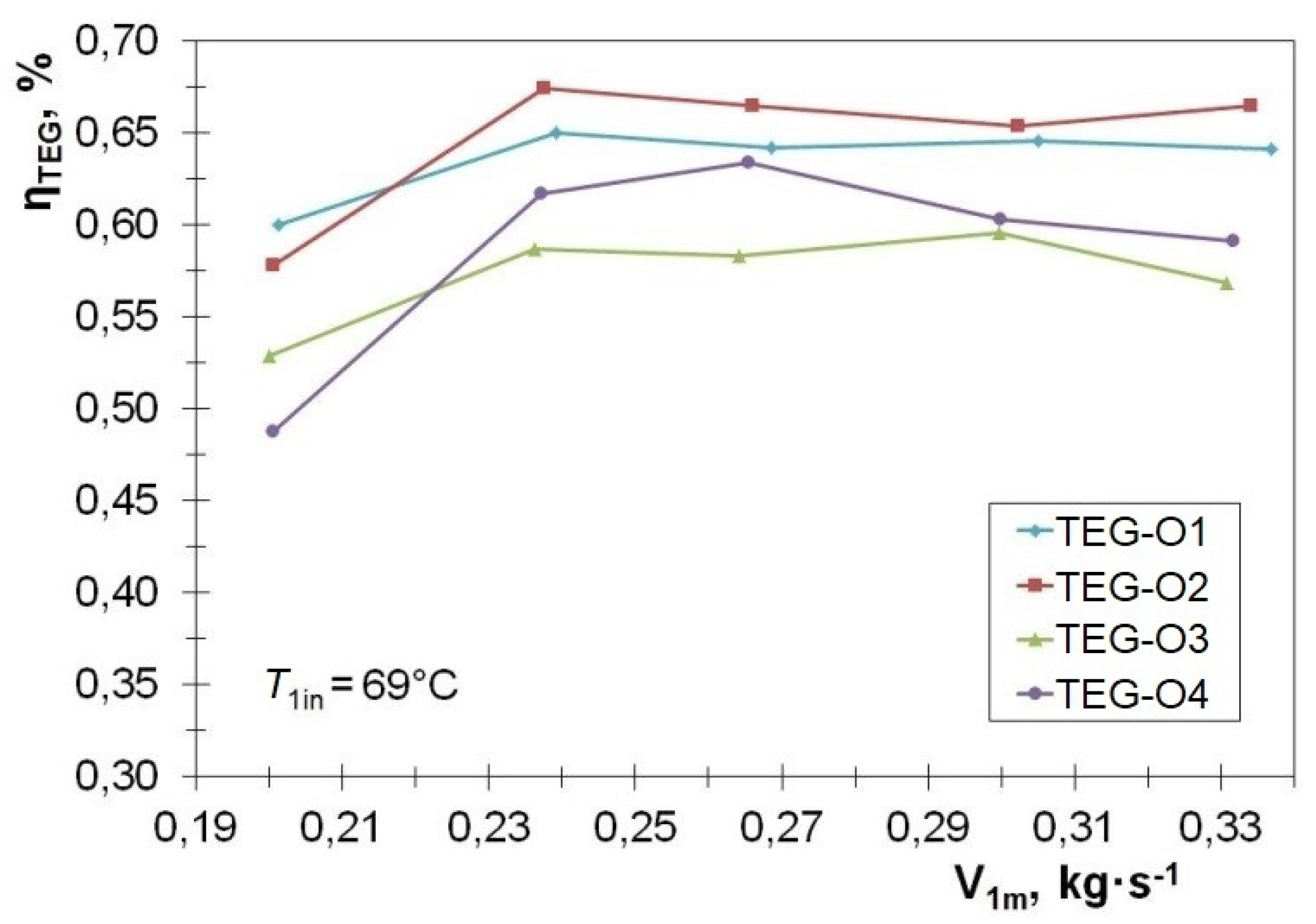
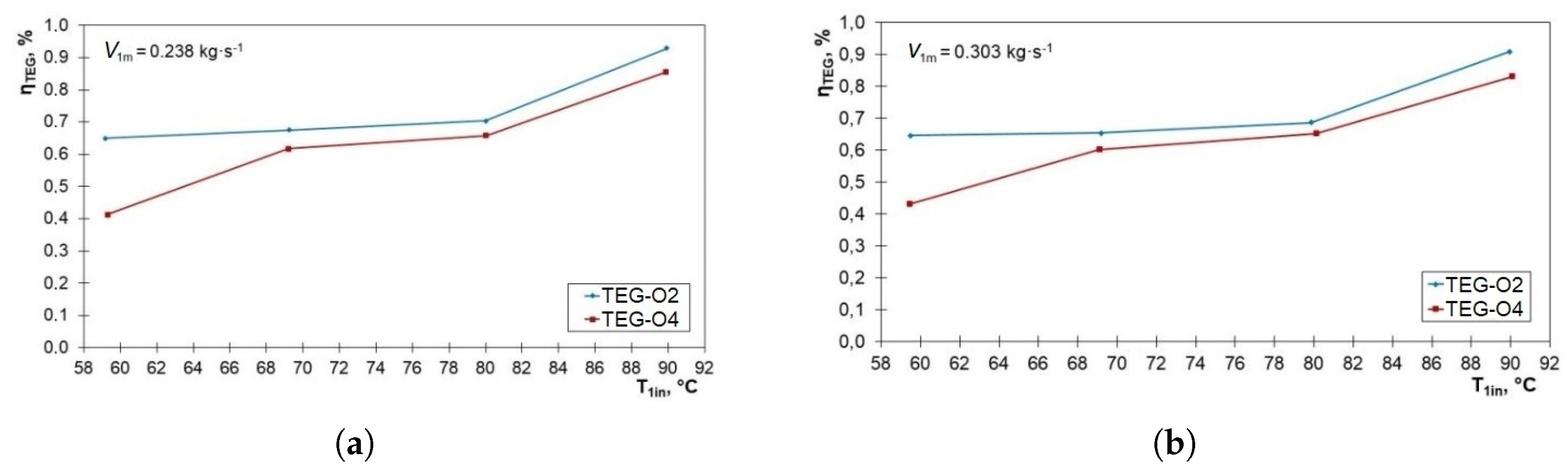
3.3. Efficiency of Energy Conversion in the TEG Module
4. Conclusions
Author Contributions
Funding
Institutional Review Board Statement
Informed Consent Statement
Conflicts of Interest
Abbreviations
| CSHE | cold side heat exchanger |
| HS | heat source |
| HSHE | hot side heat exchanger |
| MTEG | TEG grouped in modules |
| TEG | thermoelectric generators |
| THM | set of thermoelectric generators |
| Nomenclature | |
| initial liquid temperature, C | |
| liquid outlet temperature, C | |
| liquid temperature entering the HSHE, C | |
| hot-side temperature, C | |
| cold-side temperature, C | |
| temperature difference between hot and cold side of the TEG module, C | |
| heat flux entering the HSHE, W | |
| heat flux leaving the HSHE, W | |
| heat flux absorbed at the hot junction of the MTEG, W | |
| heat flux sank at the cold junction of the MTEG, W | |
| power needs for pressure losses, W | |
| electrical power generated by the THM, W | |
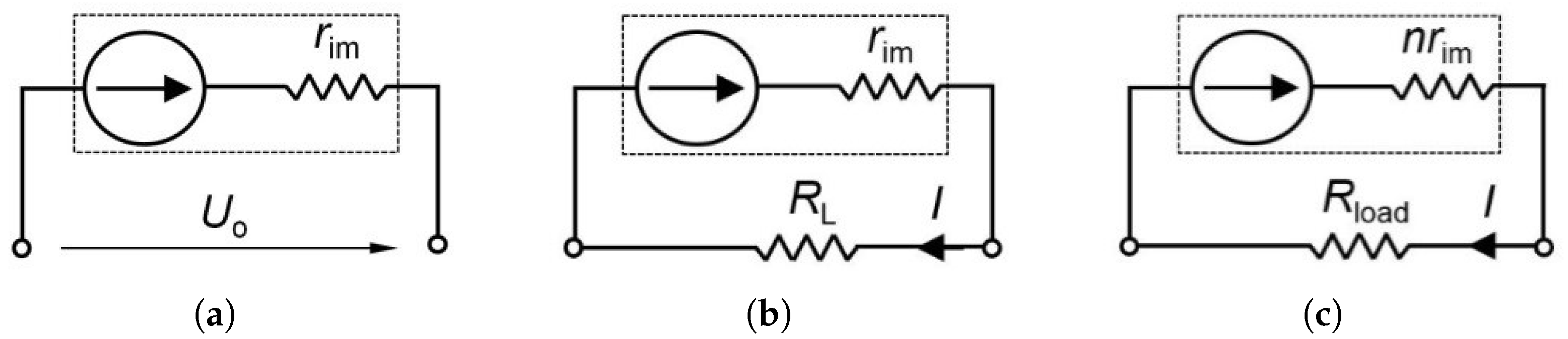
| Seebeck coefficient, V/K | |
| voltage generated by the TEG, V | |
| internal electrical resistance of the TEG, | |
| load resistance, | |
| current for the maximum power generated by the TEG, A | |
| I | electrical current, A |
| N | number of couples in the TEG |
| initial liquid mass flow rate, kg/s | |
| n | number of the TEG in the THM |
| load resistance of the single TEG, | |
| HSHE effectiveness, % | |
| MTEG efficiency, % | |
| thermal conductance of the TEG, W/K | |
| flow rate in the CSHE, % | |
| initial liquid temperature in the CSHE, % |
References
- Jaziri, N.; Boughamoura, A.; Müller, J.; Mezghani, B.; Tounsi, F.; Ismail, M. A comprehensive review of Thermoelectric Generators: Technologies and common applications. Energy Rep. 2020, 6, 264–287. [Google Scholar] [CrossRef]
- Twaha, S.; Zhu, J.; Yan, Y.; Li, B. A comprehensive review of thermoelectric technology: Materials, applications, modeling and performance improvement. Renew. Sustain. Energy Rev. 2016, 65, 698–726. [Google Scholar] [CrossRef]
- Goupil, C.; Seifert, W.; Zabrocki, K.; Muller, E.; Snyder, G.J. Thermodynamics of Thermoelectric Phenomena and Applications. Entropy 2011, 13, 1481–1517. [Google Scholar] [CrossRef] [Green Version]
- Machacek, Z.; Walendziuk, W.; Sotola, V.; Slanina, Z.; Petras, R.; Schneider, M.; Masny, Z.; Idzkowski, A.; Koziorek, J. An Investigation of Thermoelectric Generators Used as Energy Harvesters in a Water Consumption Meter Application. Energies 2021, 14, 3768. [Google Scholar] [CrossRef]
- Quan, R.; Liu, G.; Wang, C.; Zhou, W.; Huang, L.; Deng, Y. Performance Investigation of an Exhaust Thermoelectric Generator for Military SUV Application. Coatings 2018, 8, 45. [Google Scholar] [CrossRef] [Green Version]
- Rezania, A.; Rosendahl, L.A. Thermal effect of a thermoelectric generator on parallel microchannel heat sink. Energy 2012, 37, 220–227. [Google Scholar] [CrossRef]
- Rowe, D.M.; Min, G. Evaluation of thermoelectric modules for power generation. J. Power Sources 1998, 73, 193–198. [Google Scholar] [CrossRef]
- Goldsmid, H.J. Bismuth Telluride and Its Alloys as Materials for Thermoelectric Generation. Materials 2014, 7, 2577–2592. [Google Scholar] [CrossRef] [Green Version]
- Elsheikh, M.H.; Shnawah, D.A.; Sabri, M.F.M.; Said, S.B.M.; Hassan, M.H.; Bashir, M.B.A.; Mohamad, M. A review on thermoelectric renewable energy: Principle parameters that affect their performance. Renew. Sustain. Energy Rev. 2014, 30, 337–355. [Google Scholar] [CrossRef]
- Riffat, S.B.; Ma, X. Review thermoelectrics: A review of present and potential applications. Appl. Therm. Eng. 2003, 23, 913–935. [Google Scholar] [CrossRef]
- Zuazua-Ros, A.; Martin-Gomez, C.; Ibanez-Puy, E.; Vidaurre-Arbizu, M.; Gelbstein, Y. Investigation of the thermoelectric potential for heating, cooling and ventilation in buildings: Characterization options and applications. Renew. Energy 2019, 131, 229–239. [Google Scholar] [CrossRef]
- Zoui, M.A.; Bentouba, S.; Stocholm, J.G.; Bourouis, M. A Review on Thermoelectric Generators: Progress and Applications. Energies 2020, 13, 3606. [Google Scholar] [CrossRef]
- Lv, S.; Qian, Z.; Hu, D.; Li, X.; He, W. A Comprehensive Review of Strategies and Approaches for Enhancing the Performance of Thermoelectric Module. Energies 2020, 13, 3142. [Google Scholar] [CrossRef]
- Garud, K.S.; Seo, J.H.; Patil, M.S.; Bang, Y.M.; Pyo, Y.D.; Cho, C.P.; Lee, M.Y. Thermal–electrical–structural performances of hot heat exchanger with different internal fins of thermoelectric generator for low power generation application. J. Therm. Anal. Calorim. 2020, 143, 387–419. [Google Scholar] [CrossRef]
- Crane, D.T.; Jackson, G.S. Optimization of cross flow heat exchangers for thermoelectric waste heat recovery. Energy Convers. Manag. 2004, 45, 1565–1582. [Google Scholar] [CrossRef]
- Esarte, J.; Gao, M.; Rowe, D.M. Modelling heat exchangers for thermoelectric generators. J. Power Sources 2001, 93, 72–76. [Google Scholar] [CrossRef]
- Su, C.Q.; Zhan, W.W.; Shen, S. Thermal Optimization of the Heat Exchanger in the Vehicular Waste-Heat Thermoelectric Generations. J. Electron. Mater. 2012, 41, 1693–1697. [Google Scholar] [CrossRef]
- Yu, J.; Zhao, H. A numerical model for thermoelectric generator with the parallel-plate heat exchanger. J. Power Sources 2007, 172, 428–434. [Google Scholar] [CrossRef]
- Łęcki, M.; Andrzejewski, D.; Gutkowski, A.N.; Górecki, G. Study of the Influence of the Lack of Contact in Plate and Fin and Tube Heat Exchanger on Heat Transfer Efficiency under Periodic Flow Conditions. Energies 2021, 14, 3779. [Google Scholar] [CrossRef]
- Mrozek, M.; Majcher, A. Application of thermoelectric generators for electrical energy production with a low-temperature heating source. J. Mach. Constr. Maint. Probl. Eksploat. 2017, 4, 123–130. [Google Scholar]
- Hebei, TEC1-12730 Datasheet. Available online: http://www.hebeiltd.com.cn/peltier.datasheet/TEC1-12730.pdf (accessed on 8 June 2021).
- European Commission Directorate-General For Energy, Directorate C. 2—New Energy Technologies, Innovation and Clean Coal: Mapping and Analyses of the Current and Future (2020–2030) Heating/Cooling Fuel Deployment (Fossil/Renewables). Final Report. September 2016. Available online: https://irees.de/wp-content/uploads/2021/01/Scenarios-for-heating-cooling-demand-and-supply.pdf (accessed on 28 February 2017).
- Evaluation of Measurement Data—Guide to the Expression of Uncertainty in Measurement. JCGM 100:2008. Available online: https://www.bipm.org/documents/20126/2071204/JCGM_100_2008_E.pdf/cb0ef43f-baa5-11cf-3f85-4dcd86f77bd6 (accessed on 2 July 2021).
- Neska, M.; Majcher, A. Estimation of the uncertainty of measurement in a two-channel system for tests on the intensity of infrared radiation. Probl. Eksploat. Maint. Probl. 2014, 3, 45–55. [Google Scholar]
- Irshad, K.; Habib, K.; Thirumalaiswamy, N.; Saha, B.B. Performance analysis of a thermoelectric air duct system for energy-efficient buildings. Energy 2015, 91, 1009–1017. [Google Scholar] [CrossRef]
- Kin, L.K.; Baheta, A.T.; Habib, K. Analytical Investigation of Thermoelectric Performance for Cooling Application. J. Adv. Res. Fluid Mech. Therm. Sci. 2018, 46, 32–40. [Google Scholar]


| Parameter | Value |
|---|---|
| Dimensions of the module | 62 × 62 × 3.9 mm |
| Number of modules | 20 |
| Surface area of internal side of the heat exchanger | 1332.8 cm |
| Current of the generated power | 2.52 A |
| Voltage of the generated power | 1.84 V |
| Resistance of the module (C) | 0.31 |
| Max. power of the module (C) | 4.63 W |
| Total max. electric power of modules | 92.6 W |
| Max. operating temperature | 138 C |
| P–N Junction | 127 couples |
| Component/Parameter | Material/Medium | Description/Value |
|---|---|---|
| heat exchanger | aluminum alloy | dimensions: 680 × 200 × 68 mm, |
| mass: ≈25 kg | ||
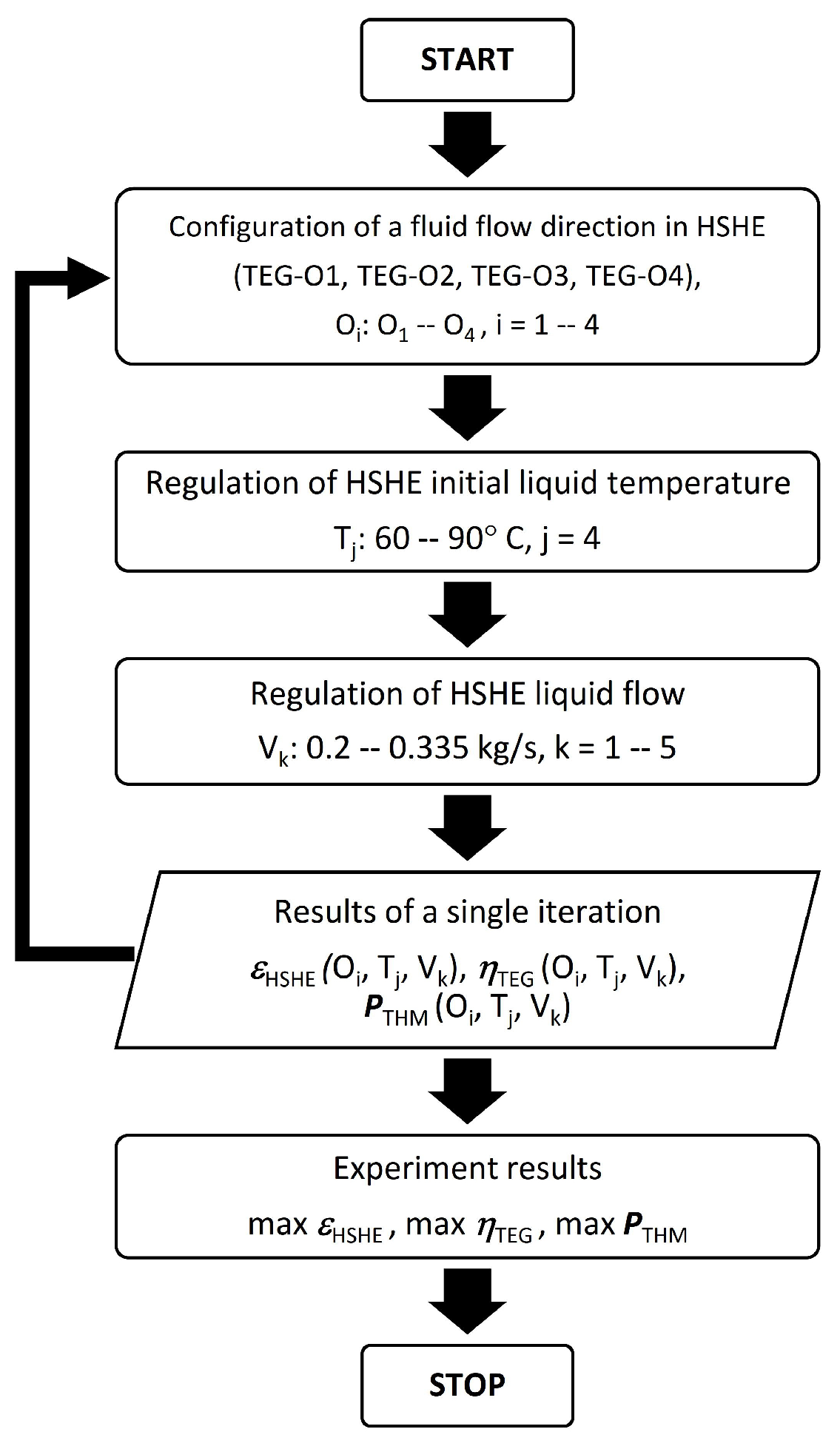
| water | 0.200–0.335 kg/s | |
| water | 60–90C | |
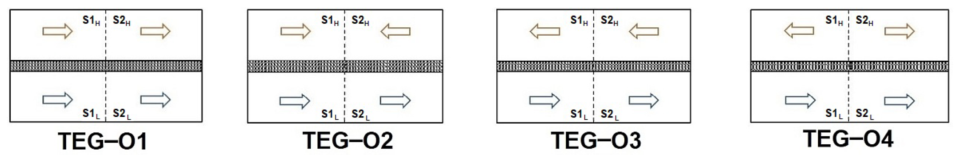
| HSHE circulations | water | variable flow directions: |
| TEG_O1, TEG_O2, TEG_O3, TEG_O4 | ||
| HSHE sections | S1, S2 | |
| water | ≈0.335 kg/s | |
| water | 9–22C | |
| CSHE circulations | water | constant |
| CSHE sections | S1, S2 |
Publisher’s Note: MDPI stays neutral with regard to jurisdictional claims in published maps and institutional affiliations. |
© 2021 by the authors. Licensee MDPI, Basel, Switzerland. This article is an open access article distributed under the terms and conditions of the Creative Commons Attribution (CC BY) license (https://creativecommons.org/licenses/by/4.0/).
Share and Cite
Neska, M.; Mrozek, M.; Żurek-Mortka, M.; Majcher, A. Analysis of the Parameters of the Two-Sections Hot Side Heat Exchanger of the Module with Thermoelectric Generators. Energies 2021, 14, 5169. https://doi.org/10.3390/en14165169
Neska M, Mrozek M, Żurek-Mortka M, Majcher A. Analysis of the Parameters of the Two-Sections Hot Side Heat Exchanger of the Module with Thermoelectric Generators. Energies. 2021; 14(16):5169. https://doi.org/10.3390/en14165169
Chicago/Turabian StyleNeska, Mirosław, Mirosław Mrozek, Marta Żurek-Mortka, and Andrzej Majcher. 2021. "Analysis of the Parameters of the Two-Sections Hot Side Heat Exchanger of the Module with Thermoelectric Generators" Energies 14, no. 16: 5169. https://doi.org/10.3390/en14165169