Article

Thermodynamic Analysis and Systematic Comparison of Solar-Heated Trigeneration Systems Based on ORC and Absorption Heat Pump

by
Jesús García-Domínguez
* and
J. Daniel Marcos
Department of Energy Engineering, National Distance Education University, UNED, 28040 Madrid, Spain
*
Author to whom correspondence should be addressed.
Energies 2021, 14(16), 4770; https://doi.org/10.3390/en14164770
Submission received: 15 July 2021 / Revised: 31 July 2021 / Accepted: 1 August 2021 / Published: 5 August 2021
(This article belongs to the Topic Multi-Energy Systems)

Abstract

:
Modular and scalable distributed generation solutions as combined cooling, heating and power (CCHP) systems are currently a promising solution for the simultaneous generation of electricity and useful heating and cooling for large buildings or industries. In the present work, a solar-heated trigeneration approach based on different organic Rankine cycle (ORC) layouts and a single-effect H2O/LiBr absorption heat pump integrated as a bottoming cycle is analysed from the thermodynamic viewpoint. The main objective of the study is to provide a comprehensive guide for selecting the most suitable CCHP configuration for a solar-heated CCHP system, following a systematic investigation approach. Six alternative CCHP configurations based on single-pressure and dual-pressure ORC layouts, such as simple, recuperated and superheated cycles, and their combinations, and seven organic fluids as working medium are proposed and compared systematically. A field of solar parabolic trough collectors (SPTCs) used as a heat source of the ORC layouts and the absorption heat pump are kept invariant. A comprehensive parametric analysis of the different proposed configurations is carried out for different design operating conditions. Several output parameters, such as energy and exergy efficiency, net electrical power and electrical to heating and cooling ratios are examined. The study reveals that the most efficient CCHP configuration is the single-pressure ORC regenerative recuperated superheated cycle with toluene as a working fluid, which is on average 25% and 8% more efficient than the variants with single-pressure simple cycle and the dual-pressure recuperated superheated cycle, respectively. At nominal design conditions, the best performing CCHP variant presents 163.7% energy efficiency and 12.3% exergy efficiency, while the electricity, cooling and heating productions are 56.2 kW, 223.0 kW and 530.1 kW, respectively.

1. Introduction

One of the potential applications that combine the use of low or medium temperature solar energy and organic Rankine cycle (ORC) is a trigeneration thermal system, which can be defined as combined cooling, heating and power (CCHP) production simultaneously from the same energy source [1]. In this regard, the thermodynamic analysis to optimise the performance of this system is an important area of research to improve energy efficiency.
In particular for ORC technology, in the last few years, different investigations have been carried out aimed at evaluating its technical, economic and market penetration differentiating its wide range of application according to the driven energy source [2,3,4,5,6,7]. In order to compare different configurations of the ORC system and different working fluids, Branchini et al. [8] carried out a parametric analysis through different performance indexes, concluding that both the evaporation pressure and the maximum temperature of the heat source are determining parameters in the performance of the power cycle. Delgado-Torres et al. [9] carried out an analysis and optimisation of a low temperature solar driven ORC system considering different solar collector technologies as well as different cycle configurations and organic working fluids. The results obtained indicate that a recovery stage downstream of the turbine implies higher average temperatures in the cycle, and therefore, higher cycle efficiency.
Likewise, for CCHP systems based on ORC power cycle, several studies were done in recent years to determine the thermal and economic performance for different system configurations [10,11,12,13,14,15]. Al-Sulaiman et al. [16] analysed and compared three CCHP systems with different prime mover approaches: a solid oxide fuel cell (SOFC), a biomass boiler and SPTCs. The results indicated that the maximum electrical efficiency is achieved for the SOFC system with a value of 19%, being 15% for the biomass system, and 15% for the solar energy system. Al-Sulaiman et al. [17] designed and assessed a trigeneration system driven by solar parabolic trough collectors (SPTCs) to produce 500 kW of electricity through an ORC system. The results show that the maximum electrical efficiency is 15%, while the overall efficiency of the CCHP is 94%. Suleman et al. [18] proposed a new system combining solar and geothermal energy as prime movers for multigeneration applications. The overall energy and exergy efficiencies of the system are found to be 54.7% and 76.4%, respectively. Bellos and Tzivanidis [19] analysed a solar-driven CCHP system through a parametric optimisation for different working fluids and design parameters. In the optimum case, the electric exergy and energy efficiency found are 27.9% and 22.5%, respectively, while the energetic performance varied from 130% to 180%.
The use of SPTCs in combination with different ORC layouts and absorption heat pumps for trigeneration systems have been already examined to date. However, there are no known studies aimed at optimising solar-powered trigeneration systems by means of systematic comparison of multiple ORC configuration and the correspondent parametric analysis. Therefore, the current investigation has a significant contribution by analysing and optimising the use of concentrated solar energy and ORC technology as a prime mover for a trigeneration plant. In this paper, the performance of six alternative CCHP configurations based on single-pressure and dual-pressure ORC layouts, such as simple, recuperated, and superheated cycles, and their combinations, is analysed and compared, considering seven working fluids. All the analysed CCHP configurations are fed with thermal input from SPTCs through a close loop that constrains the minimum temperature of the heat source at the evaporator outlet. A single-effect H2O/LiBr absorption heat pump is integrated as a bottoming cycle to meet heating and cooling demands simultaneously.
The objective of this work is twofold: on one hand, to provide a comprehensive guide for selecting the most suitable solar-heated CCHP configuration in terms of system energy and exergy efficiency by means of a fair systematic comparison between the six layouts and the seven working fluids; on the other, to evaluate parametrically all the CCHP alternatives for a wide range of solar field outlet temperature and ORC condensation temperature aiming for the design of the most efficient system that may be coupled with buildings or industries for combined generation, or as a back-up, of electricity, cooling and heating.

2. Thermodynamic Analysis of CCHP Solutions

The CCHP system assessed in this study is mainly composed of an ORC as a power generator, which is driven by a field of SPTCs. Six alternative ORC layouts are compared under steady-state conditions and seven organic fluids are considered as working medium. A single-effect H2O/LiBr absorption heat pump is integrated as a bottoming cycle to meet heating and cooling demands simultaneously.

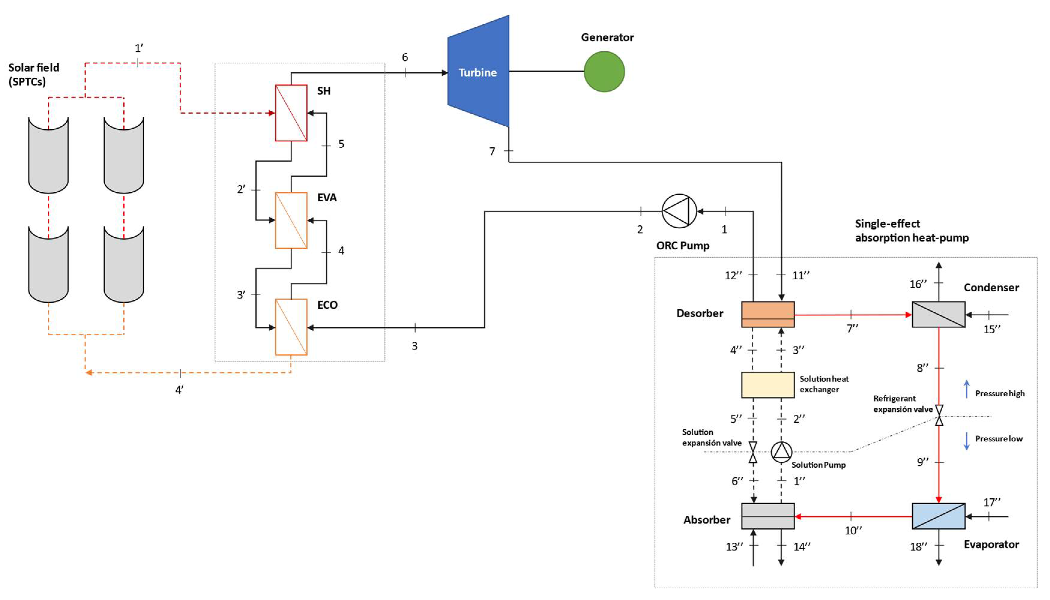
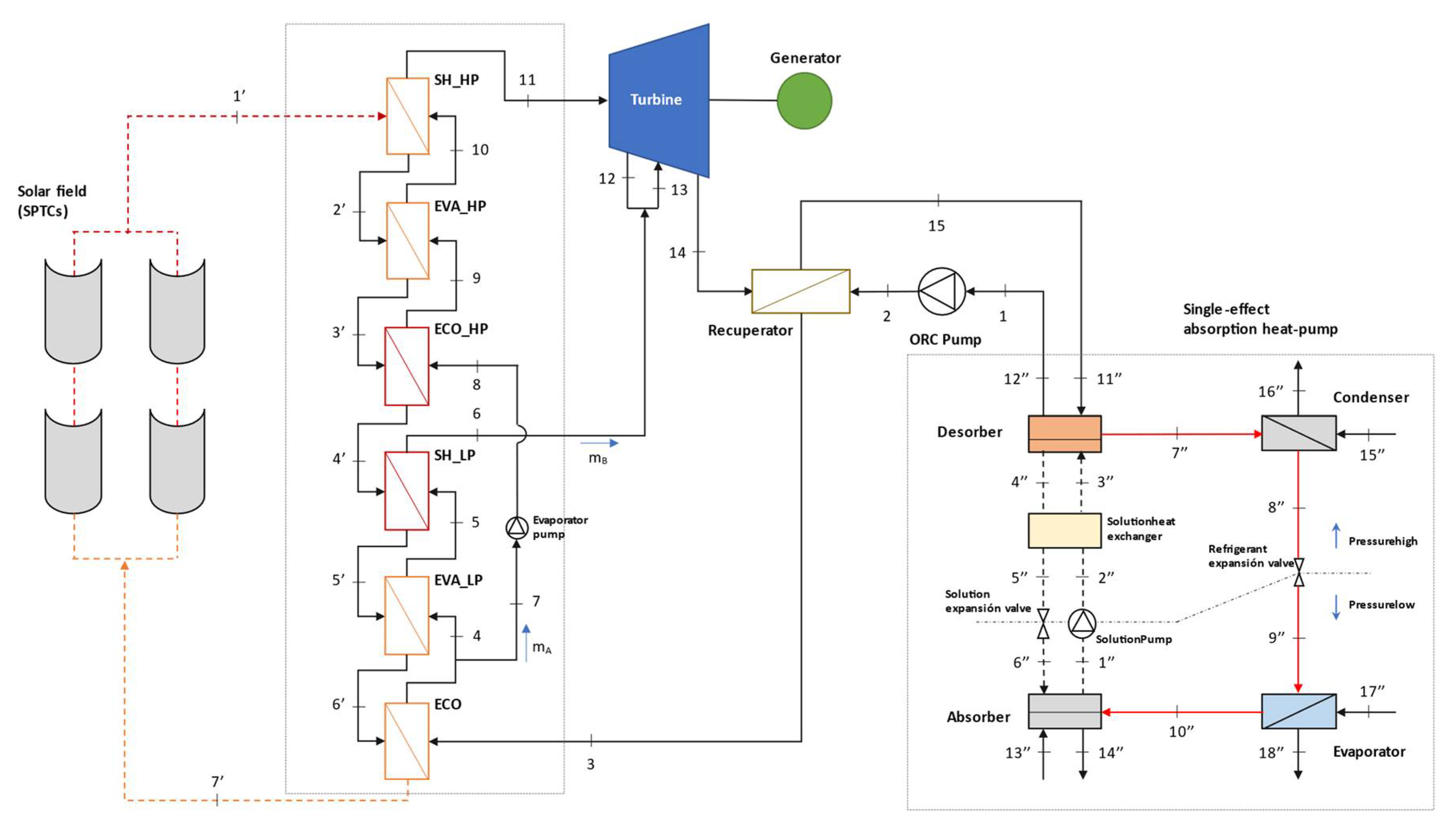
2.1. Investigated Thermodynamic CCHP Configurations

In order to determine the most suitable solar-heated CCHP configuration, a thermodynamic analysis is conducted for the six configurations represented in Figure 1, Figure 2, Figure 3, Figure 4, Figure 5 and Figure 6. The six ORC layouts are: (i) single-pressure simple cycle (1P SC), (ii) single-pressure superheated cycle (1P SH), (iii) single-pressure recuperated cycle (1P REC), (iv) single-pressure recuperated superheated cycle (1P REC + SH), (v) single-pressure regenerative recuperated superheated cycle (1P REG + REC + SH) and (vi) dual-pressure recuperated superheated cycle (2P REC + SH).
The selection of the appropriate working fluid plays a highly important role in the system design as the ORC energy and exergy efficiency must be as high as possible, and the fluid must be chemically stable in the selected working temperature range. Environmental and safety issues must also be considered. For the present work, seven organic working fluids have been selected in order to deal with solar field outlet temperature values between 180 °C and 260 °C, typical values for a field of SPTCs used in existing ORC systems.

2.2. CCHP Performance Indexes

The overall performance assessment equations of the CCHP considered are presented in this section. The energy and exergy efficiency of the ORC are calculated, taking into account the efficiency of SPTC. The Petela model [20] is used for the exergy flow of the solar irradiation presented in Equation (7).
η e n , O R C = W t u r b W O R C , p u m p Q s o l ; f o r   C a s e s   1 4 η e n , O R C = W t u r b W O R C , p u m p 1 W O R C , p u m p 2 Q s o l ; f o r   C a s e   5 η e n , O R C = W t u r b W O R C , p u m p W E v a p , p u m p Q s o l ; f o r   C a s e   6
η e x , O R C = W t u r b W O R C , p u m p Q s o l · ( 1 4 3 · T 0 T s u n + 1 3 · ( T 0 T s u n ) 4 ) ; f o r   C a s e s   1 4 η e x , O R C = W t u r b W O R C , p u m p 1 W O R C , p u m p 2 Q s o l · ( 1 4 3 · T 0 T s u n + 1 3 · ( T 0 T s u n ) 4 ) ; f o r   C a s e   5 η e x , O R C = W t u r b W O R C , p u m p W E v a p , p u m p Q s o l · ( 1 4 3 · T 0 T s u n + 1 3 · ( T 0 T s u n ) 4 ) ; f o r   C a s e   6
where:
W t u r b = m ˙ O R C · ( h 4 h 5 ) ; f o r   C a s e   1 W t u r b = m ˙ O R C · ( h 6 h 7 ) ; f o r   C a s e s   2 ,   4 W t u r b = m ˙ O R C · ( h 5 h 6 ) ; f o r   C a s e   3 W t u r b = ( m ˙ O R C , A + m ˙ O R C , B ) · h 8 m ˙ O R C , A · h 9 m ˙ O R C , B · h 10 ; f o r   C a s e   5 W t u r b = m ˙ O R C , A · ( h 11 h 12 ) + ( m ˙ O R C , A + m ˙ O R C , B ) · ( h 13 h 14 ) ; f o r   C a s e   6
W O R C , p u m p = m ˙ O R C · ( h 2 h 1 ) ; f o r   C a s e s   1 4 W O R C , p u m p 1 = m ˙ O R C · ( h 2 h 1 ) ; f o r   C a s e   5 W O R C , p u m p 2 = m ˙ O R C · ( h 5 h 4 ) ; f o r   C a s e   5 W E v a p , p u m p = m ˙ O R C · ( h 8 h 7 ) ; f o r   C a s e   6
Q s o l = D N I · w a p · L S P T C · N S P T C
The energy and exergy efficiency of the trigeneration system are defined as
η e n , t r i = ( W t u r b W O R C , p u m p + Q e + Q a + Q c Q s o l ) ; f o r   C a s e s   1 4 η e n , t r i = ( W t u r b W O R C , p u m p 1 W O R C , p u m p 2 + Q e + Q a + Q c Q s o l ) ; f o r   C a s e   5 η e n , t r i = ( W t u r b W O R C , p u m p W E v a p , p u m p + Q e + Q a + Q c Q s o l ) ; f o r   C a s e   6
η e x , t r i = ( W t u r b W O R C , p u m p + Q e · ( t 0 / t 17 1 ) + ( Q a + Q c ) · ( 1 t 0 / t 13 ) Q s o l · ( 1 4 3 · T 0 T s u n + 1 3 · ( T 0 T s u n ) 4 ) ) ; f o r   C a s e s   1 4 η e x , t r i = ( W t u r b W O R C , p u m p 1 W O R C , p u m p 2 + Q e · ( t 0 / t 17 1 ) + ( Q a + Q c ) · ( 1 t 0 / t 13 ) Q s o l · ( 1 4 3 · T 0 T s u n + 1 3 · ( T 0 T s u n ) 4 ) ) ; f o r   C a s e   5 η e x , t r i = ( W t u r b W O R C , p u m p W E v a p , p u m p + Q e · ( t 0 / t 17 1 ) + ( Q a + Q c ) · ( 1 t 0 / t 13 ) Q s o l · ( 1 4 3 · T 0 T s u n + 1 3 · ( T 0 T s u n ) 4 ) ) ; f o r   C a s e   6
The coefficient of performance (COP) of the heat pump for cooling and heating mode is defined as
C O P c o o l = Q e Q d + W S . p u m p
C O P h e a t = Q c + Q a Q d + W S . p u m p

2.3. CCHP Thermodynamic Calculation Procedure and Numerical Assumptions

The mathematical modelling of the proposed trigeneration system with all its variants is based on mass and energy balances applied to each component of the system under steady-state conditions. For a given configuration and a given working fluid, the inlet and outlet thermodynamic states of each component are calculated on the basis of the same given input data and assumptions using Engineering Equations Solver (EES) software.
The energy formulations of the SPTC model (Equations (10)–(14)) are based on the equations presented in [21] for an absorber pipe with a glass envelope, as shown in Figure 7. The energy balance in a section of the absorber pipe depends mainly on: (i) radiation losses from the glass envelope to the open sky ( q ˙ 57 r a d ) ; (ii) convection losses from the glass envelope to the environment ( q ˙ 56 c o n v ); (iii) radiation losses from the selective coating of the metal tube to the glass envelope ( q ˙ 34 r a d ); (iv) conduction losses through metal pipe supports ( q ˙ c o n d , b r a c k e t ).
All heat losses described in this section are evaluated in an analytical manner using the thermodynamic and fluid-mechanical equations and correlations governing heat transfers by conduction, convection and radiation. A stationary energy balance for the cross-section of the absorber pipe is then proposed, applying the principle of energy conservation to each of the surfaces of the section. Due to the complexity involved in this type of development, numerous simplifying hypotheses have been made. Most of these assumptions are made considering that temperatures, heat fluxes and thermodynamic properties are uniform around the perimeter of the absorber pipe.
Absorber inner surface. The useful heat that the solar thermal oil receives is the result of transfer by conduction through the absorber tube.
q ˙ 12 c o n v = q ˙ 23 c o n d
Absorber outer surface. The heat that the surface of the absorber receives from the sun, after taking into account both the optical and geometric effects of the collector, is the result of the sum of the heat fluxes due to the absorber–glass radiation, internal convection, heat loss through the absorber pipe support brackets and the fraction of energy that is finally conducted through the thickness of the absorber pipe into the fluid.
q ˙ 3 S o l A b s = q ˙ 23 c o n d + q ˙ 34 r a d + q ˙ 34 c o n v + q ˙ c o n d , b r a c k e t
Glass envelope inner surface. The heat that is evacuated from the absorber outer surface through the space between the absorber and the glass envelope (regardless of whether there is a vacuum or not) is the same as that is transferred by conduction through the thickness of the glass.
q ˙ 34 r a d + q ˙ 34 c o n v = q ˙ 45 c o n d
Glass envelope outer surface. The heat that falls upon the external surface is in balance with the heat that the system releases to the outside from the external surface of the glass envelope.
q ˙ 5 S o l A b s + q ˙ 45 c o n d = q ˙ 56 c o n v + q ˙ 57 r a d
Considering that the region between the absorber pipe and the glass envelope has been vacuumed, the convective heat transfer between the two surfaces ( q ˙ 34 c o n v ) can be considered negligible. Hence, under these assumptions, the useful thermal power ( q ˙ 12 c o n v ) can be reformulated as follows:
q ˙ u t i l = q ˙ 3 S o l A b s + q ˙ 5 S o l A b s ( q ˙ 56 c o n v + q ˙ 57 r a d + q ˙ c o n d , b r a c k e t )
The overall efficiency of the SPTC considers all types of losses [21,22]: optical, geometric and thermal, and it can be defined as the ratio between the useful thermal power delivered to the solar thermal oil, and the solar resource available based on the direct normal irradiance (DNI).
η S P T C = q ˙ u q ˙ s o l = q ˙ u D N I ·   w a p
where q ˙ u is defined as
q ˙ u = m ˙ s o l C p s o l ( T s o l . o u t T s o l . i n ) L S P T C
The solar field includes SPTCs (PTMx-24 from the company Soltigua) with a total collecting area of 617.4 m2, consisting of five rows with two collectors per row. The specifications of the collector and the parameters of the solar system that have been selected in this analysis are defined in Table 1. The selected values are reasonable, and they were taken from Refs [9,17,19,21].
The ORC modelling is performed for the six CCHP configuration variants represented in Figure 1, Figure 2, Figure 3, Figure 4, Figure 5 and Figure 6. Apart from the inputs coming from the solar field model, which are the solar field outlet temperature and mass flow rate, the key input thermodynamic variables required for the calculations are:
  • The turbine isentropic efficiency;
  • The ORC pump isentropic efficiency;
  • For SH cycles, the superheating temperature;
  • For REC cycles, the recuperator effectiveness;
  • The condensation temperature.
For the ORC layouts corresponding to Case 5 and Case 6, the extraction pressure is selected strategically between condensation and evaporation pressures with the aim to obtain the maximum thermodynamic efficiency of each cycle.
The evaporator, or so-called heat recovery system, is the element that serves as the link between the heat source, provided by the SPTCs, and the steam cycle. In the evaporator, the fluid passes through different stages depending on the ORC layout considered. Initially, in the economiser the fluid is heated to the fluid evaporation temperature minus a Delta T, called the approach point (AP); in the evaporator, heat is added to the saturated liquid to produce saturated vapor at constant temperature and pressure. In case a superheater is considered, the saturated vapor is heated above the evaporation temperature until design conditions are reached. The evaporator design parameters used in the study are the pinch point (PP)—difference between the solar field mass flow and the organic fluid—the approach point (AP)—difference between the organic fluid temperature leaving the evaporator and the saturation temperature—and the live steam outlet temperature TLS. All these values are given in Table 2.
Figure 8 represents the correspondent heat transfer–temperature diagrams for a single-pressure evaporator with superheater (a) that applies to Cases 2, 4–5, and for a dual-pressure evaporator with low-pressure and high-pressure superheaters, (b) that applies to Case 6.
With regard to the absorption heat pump, several modelling studies with experimental validation for specific and generic absorption machines can be found in the literature reviewed [23,24,25,26]. In the proposed absorption heat pump model, there is a total of 18 states, each of which is determined by its temperature, pressure, enthalpy, flow, H2O/LiBr concentration, etc. The assumptions used in the single-effect absorption chiller are:
  • Saturated liquid solution at states 1 and 4;
  • Subcooled liquid solution at states 2, 3 and 5;
  • Vapor-liquid mixture solution at state 6;
  • Superheated water vapor at state 7;
  • Saturated water liquid at high pressure at state 8;
  • Vapor-liquid mixture (water) at state 9;
  • Saturated water vapor at low pressure at state 10.
The input data used in the absorption heat pump model is given in Table 3. The selected values are reasonable and conservative to avoid the formation of crystals from the H2O/LiBr solution.

3. Results and Discussion

In the framework of the above constraints and assumptions, the methodology pursued to analyse the CCHP configuration variants from the thermodynamic viewpoint is organised as follow. First of all, for a given configuration and a given working fluid, an analysis of each pair is performed according to the nominal conditions indicated in Table 1, Table 2 and Table 3. Then, a systematic comparison of each combination is carried out by means of the evaluation of the performance indexes indicated in Section 2.1. Thereafter, a parametric approach is conducted for the best pair (configuration variant and working fluid) to evaluate the effect of different system operating parameters on the energy and exergy efficiency of the ORC and on the overall CCHP system performance. Finally, for each of the identified best pair, a muti-objective optimisation study is performed based on the same operating parameters following the criteria of system energy and exergy.
With such methodology, it is possible to determine the best performing CCHP variant in terms of system energy and exergy efficiency within the six analysed alternatives and for the seven organic working fluids, and on the other hand, to assess how the variation of some design operating parameters can affect the performance of the system and what the optimum values for such parameters are for each variant in terms of system performance.

3.1. Analysis of CCHP Variants

Table 4, Table 5 and Table 6 represent the energy and exergy efficiency of the ORC and the overall CCHP system performance for each of the proposed CCHP configurations and organic working fluids at nominal conditions, indicated in Table 1, Table 2 and Table 3.
The performance indexes indicated in Table 4, Table 5, Table 6, Table 7, Table 8 and Table 9 show that for the six CCHP configurations and the seven organic working fluids analysed, the best performing variant is the CCHP with single-pressure ORC regenerative recuperated superheated cycle (Case 5) with toluene as a working fluid. The achieved energy and exergy efficiency are: 11.24% and 12.04%, respectively, for the ORC, and 163.7% and 12.3%, respectively, for the CCHP. The electricity, cooling and heating productions are 56.2 kW, 222.3 kW and 530.1 kW, respectively. On average for the seven working fluids considered, in terms of ORC energy efficiency Case 5 is 25% more efficient than Case 1 (1P SC). In terms of which organic working fluid is best suited depending on the configuration, benzene performs best for Cases 1 and 2, and toluene for Cases 3–6.
A CCHP with a single-pressure ORC superheated cycle (Case 2) only results in an increase in efficiency if a recovery stage is available downstream of the turbine. The performance indexes show that on average for the seven working fluids considered, in terms of ORC energy efficiency, Case 2 is 1.6% less efficient than Case 1 (1P SC).
The main objective in evaporator design is to minimise losses and maximise heat transfer from the solar heat source. This is achieved by introducing multiple pressure levels; as the temperature curves of the heat source and the organic fluid are better adapted to each other (see Figure 8b) the efficiency of the evaporator increases, but also its complexity and cost, as more heat exchangers are introduced. The results obtained for Case 6 (2P REC + SH) show that the fact to include two pressure levels in the evaporator does not imply a performance improvement of the CCHP system in comparison with Case 3 (1P REC), Case 4 (1P REC + SH) and Case 5 (1P REG + REC + SH); in fact, on average, for the seven working fluids considered, in terms of ORC energy efficiency Case 6 is about 8% less efficient than Case 5. This is explained because the temperature of the heat source at the evaporator outlet is constrained by the close loop of SPTCs, which impacts on the capacity of the dual-pressure evaporator to maximise the heat recovery from the solar heat source.

3.2. Parametric Analysis

In this subsection, a parametric approach is conducted for the best pair analysed previously (configuration variant and working fluid) to evaluate the effect of different system parameters on the energy and exergy efficiency of the ORC and on the overall CCHP system performance.

3.2.1. Effect of the Solar Field Outlet Temperature

The selection of an optimal evaporation temperature for the ORC is determined by the heat delivered by the solar field; a weakness of solar parabolic trough technology is the limited outlet temperature of the solar field [27]. This study aims to illustrate the influence of the solar field outlet temperature, varying in the range of 180–260 °C, on the efficiency of the ORC and on the overall trigeneration system. Table 10 and Figure 9 represent the system performance and electrical and thermal generation for each analysed pair.
As can be observed in Table 9 and Figure 10, higher values of the solar field outlet temperature mean an increase in ORC energy and exergy efficiency, and in CCHP exergy efficiency. This is due to a higher temperature of the heat source causing a higher organic fluid evaporation pressure in the ORC, leading to higher heat recovery efficiency in the evaporator. For Case 5, which is the best performing variant, with the increase in the heat source inlet temperature, the efficiency of the ORC increases from 9.0% to 16.3%. In terms of relative increase for the electricity produced by the turbine, the increase of the heat source inlet temperature of 180–260 °C represents an increase of 83% (from 45.0 kW to 82.5 kW).
For the CCHP with dual-pressure ORC (Case 6), the relative increase either for the ORC energy efficiency and electricity produced by the turbine with respect to the increase in the heat source inlet temperature of 180–260 °C is significantly greater: 90% for the ORC efficiency (from 8.2% to 15.5%) and 92% for electricity produced by the turbine (from 40.6 kW to 78.1 kW).

3.2.2. Effect of ORC Condensation Temperature

The single-effect absorption heat pump requires a certain heat input in the desorber within a specific temperature range for its operation. This inlet temperature is determined by the condensation temperature of the ORC, so it is important to identify which is the optimal operating temperature based on the production that needs to be prioritised.
In this study, the effect of the ORC condensation temperature is examined from 85 to 105 °C, and system performance and electrical and thermal generation for each analysed pair are presented in Table 11 and Figure 10.
ORC condensation temperature can be a good parameter for controlling the cooling and heating power to be produced by the absorption heat pump. It is observed that as the ORC condensation temperature increases, both the ORC energy efficiency and CCHP exergy efficiency decrease; the lower the condensing pressure, the higher the capacity to extract work from the turbine. For Case 5, with the increase of the ORC condensation temperature, the efficiency of the ORC decreases from 9.1% to 11.9%; in relative terms for the electricity produced by the turbine, the increase in the ORC condensation temperature of 85–105 °C represents a decrease of 23% (from 59.6 kW to 45.7 kW).
Regarding the energy efficiency of the trigeneration system, the effect is the opposite, as the condensation temperature increases the overall efficiency of the system also increases because the heat input to the absorption heat pump desorber is greater, and therefore the heat of the evaporator, absorber and condenser are also greater.

3.3. Optimisation Analysis

The optimisation procedure proposed is based on the optimisation of the analysed operating parameters (see Table 12), and not of the system devices, following strict energy and exergy efficiency criteria. Therefore, a multi-objective optimisation approach is considered for each of the identified best pairs requiring the simultaneous satisfaction of certain objectives, that is the ORC energy efficiency (Equation (1)) and CCHP exergy efficiency (Equation (7)).
The Pareto front is probably one of the most common approaches used for multi-objective optimisation problems in thermodynamics [28,29]. However, the most straightforward approach to solve these problems is the weighted sum method [30,31], that combines all the multi-objective functions into one scalar by summing the corresponding objectives with some appropriate weights. For the trigeneration system analysis considered in this paper, the bi-objective optimisation is constructed by summing the two beforementioned objectives with some appropriate weights, as follows:
M A X   ( M O F = w 1 · η e n , O R C + w 2 · η e x , t r i ) 0   w 1 ,   w 2   1 w 1 + w 2 = 1
where w 1 and w 2 are the weighting coefficients for the ORC energy efficiency and CCHP exergy efficiency, respectively. Though any set of optimal solutions can be chosen by selecting the desired values of weighting coefficients, the two objectives are assumed to be of the same importance. The “Conjugate Directions Method” which is supported by EES is used in the bi-objective optimal design (Equation (17)). The results obtained for each of the identified best pair are shown in Table 13.
The obtained results remark that the optimum design for all the analysed cases is produced for the maximum solar field outlet temperature (260 °C) and the minimum ORC condensation temperature (85 °C). The best performing pair is Case 5 with toluene, presenting values of ORC energy efficiency and CCHP exergy efficiency of 16.82% and 18.23%, respectively. In comparison with nominal design conditions, the optimum design for Case 5 is, in terms of ORC energy efficiency, 50% more efficient.

4. Conclusions

A comprehensive and systematic comparative thermodynamic analysis of six different solar-heated CCHP systems based on ORC and absorption heat pump is conducted. Any configuration can produce electricity, heating and cooling in temperature levels ideal for building or small-medium industry applications. The most suitable CCHP configuration has been identified in terms of system energy and exergy efficiency, as well as the best working fluid for each configuration variant. Through parametric and muti-objective optimisation analysis, it has been possible to determine how the solar field outlet temperature and the ORC condensation temperature affect the performance of the CCHP system for each best pair (configuration variant and working fluid). The main findings of the study are summarised below:
  • For the six CCHP configurations and the seven organic working fluids analysed, the best performing variant is the CCHP with single-pressure ORC regenerative recuperated superheated cycle (Case 5) with toluene as a working fluid. The achieved energy and exergy efficiency are: 11.24% and 12.04%, respectively, for the ORC, and 163.7% and 12.3%, respectively, for the CCHP. The electricity, cooling and heating productions are 56.2 kW, 222.3 kW and 530.1 kW, respectively.
  • For the seven organic working fluids analysed, benzene performs best for Cases 1 and 2, and toluene for Cases 3–6.
  • At nominal conditions and on average for the seven working fluids considered, Case 5 is about 25% more efficient than Case 1, and about 8% more efficient than Case 6 in terms of ORC energy efficiency.
  • A CCHP with single-pressure ORC superheated cycle (Case 2) only results in an increase in efficiency if a recovery stage is available downstream of the turbine.
  • The use of a dual-pressure evaporator (Case 6) does not imply a performance improvement of the CCHP system if the temperature of the heat source at the evaporator outlet is constrained.
  • A higher temperature of the solar heat source causes a higher organic fluid evaporation pressure in the ORC, leading to higher heat recovery efficiency in the evaporator and in CCHP efficiency. For Case 5 with toluene, the electricity produced by the turbine presents an increase of 83% as with the increase of the heat source inlet temperature from 180 to 260 °C.
  • As the ORC condensation temperature increases, both the ORC energy efficiency and CCHP exergy efficiency decrease. For Case 5 with toluene, the increase in the ORC condensation temperature from 85 to 105 °C represents a decrease of 23% of the electricity produced by the turbine.
  • The optimum design conditions for all the analysed cases are produced for the maximum solar field outlet temperature (260 °C) and the minimum ORC condensation temperature (85 °C). For Case 5 with toluene, in comparison with nominal design conditions, the optimum design is 50% more efficient in terms of ORC energy efficiency.

Author Contributions

Conceptualisation, J.G.-D. and J.D.M.; methodology, J.G.-D. and J.D.M.; software, J.G.-D.; validation, J.D.M.; formal analysis, J.G.-D. and J.D.M.; investigation, J.G.-D.; resources, J.G.-D. and J.D.M.; data curation, J.G.-D. and J.D.M.; writing—original draft preparation, J.G.-D.; writing—review and editing, J.G.-D. and J.D.M.; visualisation, J.G.-D.; supervision, J.D.M.; project administration, J.D.M.; funding acquisition, J.D.M. All authors have read and agreed to the published version of the manuscript.

Funding

The authors would like to acknowledge the financial support of the Regional Research and Development in Technology Programme 2018 (ref. P2018/EMT-4319) in the frame of the ACES2030-CM project.

Data Availability Statement

Data are contained within the article.

Conflicts of Interest

The authors declare no conflict of interest.

Nomenclature

Symbols
hheat transfer coefficient, W/(m2 K)
m ˙ mass flow rate, kg/s
Ttemperature, °C
ΔTtemperature difference, °C
ηefficiency
Welectric power, kW
Qthermal power, kW
q ˙ heat rate per SPTC unit length, kW/m
w a p aperture width of SPTC, m
Llength of SPTC, m
Nnumber of SPTCs
θsolar incidence angle on the SPTC, º
Acronyms
CCHPcombined cooling heating and power
ORCorganic Rankine cycle
SPTCsolar parabolic trough collector
RECrecuperator heat exchanger or recuperated cycle
REGregenerative cycle
SCsimple cycle
SHsuperheater heat exchanger or superheated cycle
DNIdirect normal irradiance
LSlive steam
PPpinch point
APapproach point
COPcoefficient of performance
LPlow pressure
Hhigh pressure
UAoverall heat transfer coefficient
Subscripts
enenergy
exexergy
solsolar field
0atmospheric conditions
ininlet
outinlet
turbturbine
condheat conduction
convheat convection
radheat radiation
SolAbssolar absorption
tritrigeneration
dheat pump desorber
aheat pump absorber
s.heheat pump solution heat exchanger
cheat pump condenser
eheat pump evaporator
Evap.pumpevaporator pump
s.pumpsolution pump
coolheat pump cooling mode
heatheat pump heating mode

References

  1. Al-Sulaiman, F.A.; Hamdullahpur, F.; Dincer, I. Trigeneration: A comprehensive review based on prime movers. Int. J. Energy Res. 2011, 35, 233–258. [Google Scholar] [CrossRef]
  2. Vélez, F.; Segovia, J.J.; Martín, M.C.; Antolín, G.; Chejnec, F.; Quijano, A. A technical, economical and market review of organic Rankine cycles for the conversion of low-grade heat for power generation. Energy Convers. Manag. 2013, 69, 209–216. [Google Scholar] [CrossRef]
  3. Quoilin, S.; Van Den Broek, M.; Declaye, S.; Dewallef, P.; Lemort, V. Techno-economic survey of Organic Rankine Cycle (ORC) systems. Renew. Sustain. Energy Rev. 2013, 22, 168–186. [Google Scholar] [CrossRef] [Green Version]
  4. Villarini, M.; Bocci, E.; Moneti, M.; Di Carlo, A.; Micangeli, A. State of art of small scale solar powered ORC systems: A review of the different typologies and technology perspectives. Energy Procedia 2014, 45, 257–267. [Google Scholar] [CrossRef] [Green Version]
  5. Li, J.; Ge, Z.; Duan, Y.; Yang, Z.; Liu, Q. Parametric optimization and thermodynamic performance comparison of single-pressure and dual-pressure evaporation organic Rankine cycles. Appl. Energy 2018, 217, 409–421. [Google Scholar] [CrossRef]
  6. Fernández-Guillamón, A.; Molina-García, Á.; Vera-García, F.; Almendros-Ibáñez, J.A. Organic Rankine Cycle Optimization Performance Analysis Based on Super-Heater Pressure: Comparison of Working Fluids. Energies 2021, 14, 2548. [Google Scholar] [CrossRef]
  7. Manente, G.; Lazzaretto, A.; Bonamico, E. Design guidelines for the choice between single and dual pressure layouts in organic Rankine cycle (ORC) systems. Energy 2017, 123, 413–431. [Google Scholar] [CrossRef]
  8. Branchini, L.; De Pascale, A.; Peretto, A. Systematic comparison of ORC configurations by means of comprehensive performance indexes. Appl. Therm. Eng. 2013, 61, 129–140. [Google Scholar] [CrossRef]
  9. Delgado-Torres, A.M.; García-Rodríguez, L. Analysis and optimization of the low-temperature solar organic Rankine cycle (ORC). Energy Convers. Manag. 2010, 51, 2846–2856. [Google Scholar] [CrossRef]
  10. Villarini, M.; Bocci, E.; Di Carlo, A.; Sbordone, D. Technical-Economic Analysis of an Innovative Small Scale Solar Thermal—ORC Cogenerative System. In International Conference on Computational Science and Its Applications Part II LNCS; Springer: Berlin/Heidelberg, Germany, 2013; Volume 7972, pp. 271–287. [Google Scholar]
  11. Hassoun, A.; Dincer, I. Analysis and performance assessment of a multigenerational system powered by Organic Rankine Cycle for a net zero energy house. Appl. Therm. Eng. 2015, 76, 25–36. [Google Scholar] [CrossRef]
  12. Khalid, F.; Dincer, I.; Rosen, M.A. Thermoeconomic analysis of a solar-biomass integrated multigeneration system for a community. Appl. Therm. Eng. 2017, 120, 645–653. [Google Scholar] [CrossRef]
  13. Bellos, E.; Tzivanidis, C. Multi-objective optimization of a solar driven trigeneration system. Energy 2018, 149, 47–62. [Google Scholar] [CrossRef]
  14. Nasir, M.T.; Ekwonu, M.C.; Park, Y.; Esfahani, J.A.; Kim, K.C. Assessment of a District Trigeneration Biomass Powered Double Organic Rankine Cycle as Primed Mover and Supported Cooling. Energies 2021, 14, 1030. [Google Scholar] [CrossRef]
  15. García-Domínguez, J.; Blanco-Marigorta, A.M.; Marcos, J.D. Thermodynamic analysis and optimization of a combined cooling, heating, and power system using Organic Rankine Cycles (ORC) and solar parabolic trough collectors. In Proceedings of the 33rd International Conference on Efficiency, Cost, Optimization, Simulation and Environmental Impact of Energy Systems, Osaka, Japan, 29 June–3 July 2020. [Google Scholar]
  16. Al-Sulaiman, F.A.; Hamdullahpur, F.; Dincer, I. Performance comparison of three trigeneration systems using organic rankine cycles. Energy 2011, 36, 5741–5754. [Google Scholar] [CrossRef]
  17. Al-Sulaiman, F.A.; Hamdullahpur, F.; Dincer, I. Performance assessment of a novel system using parabolic trough solar collectors for combined cooling, heating, and power production. Renew. Energy 2012, 48, 161–172. [Google Scholar] [CrossRef]
  18. Suleman, F.; Dincer, I.; Agelin-Chaab, M. Development of an integrated renewable energy system for multigeneration. Energy 2014, 78, 196–204. [Google Scholar] [CrossRef]
  19. Bellos, E.; Tzivanidis, C. Parametric analysis and optimization of a solar driven trigeneration system based on ORC and absorption heat pump. J. Clean. Prod. 2017, 161, 493–509. [Google Scholar] [CrossRef]
  20. Petela, R. Exergy of undiluted thermal radiation. Sol. Energy 2013, 74, 469–488. [Google Scholar] [CrossRef]
  21. Forristall, R. Heat Transfer Analysis and Modeling of a Parabolic Trough Solar Receiver Implemented in Engineering Equation Solver NREL/TP-550-34169; National Renewable Energy Laboratory: Golden, CO, USA, 2003.
  22. Rashid, K. Design, Economics, and Real-Time Optimization of a Solar/Natural Gas Hybrid Power Plant. Ph.D. Thesis, The University of Utah, Salt Lake City, UT, USA, 2019. [Google Scholar]
  23. Liao, X.; Garland, P.; Radermacher, R. The modeling of air-cooled absorption chiller integration in CHP system. ASME Int. Mech. Eng. Congr. Expo. 2004, 47012, 371–377. [Google Scholar] [CrossRef]
  24. Bakhtiari, B.; Fradette, L.; Legros, R.; Paris, J. A model for analysis and design of H2O–LiBr absorption heat pumps. Energy Convers. Manag. 2011, 52, 1439–1448. [Google Scholar] [CrossRef]
  25. Marcos, J.D.; Izquierdo, M.; Palacios, E. New method for COP optimization in water-and air-cooled single and double effect LiBr–water absorption machines. Int. J. Refrig. 2011, 34, 1348–1359. [Google Scholar] [CrossRef]
  26. Evola, G.; Le Pierre‘s, N.; Boudehenn, F.; Papillon, P. Proposal and validation of a model for the dynamic simulation of a solar-assisted single-stage LiBr/water absorption chiller. Int. J. Refrig. 2013, 36, 1015–1028. [Google Scholar] [CrossRef]
  27. Rashid, K.; Safdarnejad, S.M.; Powell, K.M. Process intensification of solar thermal power using hybridization, flexible heat integration, and real-time optimization. Chem. Eng. Process. Process Intensif. 2019, 139, 155–171. [Google Scholar] [CrossRef] [Green Version]
  28. Spelling, J.; Favrat, D.; Martin, A.; Augsburger, G. Thermoeconomic optimization of a combined-cycle solar tower power plant. Energy 2012, 41, 113–120. [Google Scholar] [CrossRef]
  29. Baghernejad, A.; Yaghoubi, M.; Jafarpur, K. Exergoeconomic optimization and environmental analysis of a novel solar-trigeneration system for heating, cooling and power production purpose. Sol. Energy 2016, 134, 165–179. [Google Scholar] [CrossRef]
  30. Kim, I.Y.; de Weck, O.L. Adaptive weighted-sum method for bi-objective optimization: Pareto front generation. Struct. Multidiscip. Optim. 2005, 29, 149–158. [Google Scholar] [CrossRef]
  31. Zare, V.; Mahmoudi, S.M.S.; Yari, M.; Amidpour, M. Thermoeconomic analysis and optimization of an ammonia-water power/cooling cogeneration cycle. Energy 2012, 47, 271–283. [Google Scholar] [CrossRef]
Figure 1. Case 1: CCHP with single-pressure ORC simple cycle (1P SC).
Energies 14 04770 g001
Figure 2. Case 2: CCHP with single-pressure ORC superheated cycle (1P SH).
Energies 14 04770 g002
Figure 3. Case 3: CCHP with single-pressure ORC recuperated cycle (1P REC).
Energies 14 04770 g003
Figure 4. Case 4: CCHP with single-pressure ORC recuperated superheated cycle (1P REC + SH).
Energies 14 04770 g004
Figure 5. Case 5: CCHP with single-pressure ORC regenerative recuperated superheated cycle (1P REG + REC + SH).
Energies 14 04770 g005
Figure 6. Case 6: CCHP with dual-pressure ORC recuperated superheated cycle (2P REC + SH).
Energies 14 04770 g006
Figure 7. One-dimensional steady-state energy balance of SPTC [21].
Energies 14 04770 g007
Figure 8. Scheme and heat transfer-temperature diagram for two variants of evaporators: (a) Single-pressure with superheater; (b) Dual-pressure with low-pressure and high-pressure superheaters.
Energies 14 04770 g008
Figure 9. Effect of the solar field outlet temperature on: (a) ORC energy efficiency; (b) CCHP exergy efficiency.
Energies 14 04770 g009
Figure 10. Effect of ORC condensation temperature on: (a) ORC energy efficiency; (b) CCHP exergy efficiency.
Energies 14 04770 g010
Table 1. Input data for SPTC model.
ParameterValue
Collector aperture width, –wap2.36 m
Collector length–LSPTC26.16 m
Collector nominal mass flow rate1 kg/s
Absorber outer diameter20.5 mm
Absorber inner diameter22 mm
Glass envelope outer diameter37.5 mm
Glass envelope inner diameter40 mm
Number of collectors-NSPTC10
Solar field outlet temperature–T1′200 °C
Ambient temperature30 °C
Reference temperature298.15 K
Sun Temperature5770 K
Direct Normal Irradiance–DNI800 W/m2
Solar incident angle
Wind velocity3 m/s
Table 2. Input data for ORC model.
ParameterValue
Condensation temperature–T190 °C
Turbine efficiency–ηturb85%
Pump isentropic efficiency-ηORC,pump, ηEvap,pump,70%
Recuperator efficiency *–ηREC70%
Superheating **–ΔTSH10 °C
Live steam outlet temperature ***–TLST1′-25 °C
Live steam outlet temperature **–TLST1′-25 °C-ΔTSH
Pinch Point–PP8 K
Approach Point–AP5 K
* For recuperated cycles (Cases 3–6). ** For superheated cycles (Cases 2, 4–6). *** For non-superheated cycles (Cases 1, 3).
Table 3. Input data for absorption heat pump model.
ParameterValue
Maximum solution concentration,–x4″65%
Condensation temperature–T13″; T15″20 °C
Condensation mass flow rate12 kg/s
Evaporation temperature–T17″12 °C
Evaporation mass flow rate15 kg/s
Solution heat exchanger efficiency–ηsol.he70%
UA desorber30 kW/K
UA condenser70 kW/K
UA absorber20 kW/K
UA evaporator30 kW/K
Table 4. Results for Case 1: CCHP with single-pressure ORC Simple cycle (1P SC).
Fluidηen,ORC
[%]
ηex,ORC
[%]
ղen,tri
[%]
ղex,tri
[%]
Wturb
[kW]
Qe
[kW]
Qa
[kW]
Qc
[kW]
Toluene9.6410.33166.1010.5848.19228.83302.41241.42
Benzene9.7410.43165.9010.6849.15228.49301.98241.06
n-heptane8.519.12167.809.3742.98232.97307.74245.83
n-octane8.569.16167.709.4242.77232.80307.53245.65
n-nonane8.539.14167.709.3942.42232.89307.64245.74
n-decane8.539.13167.709.3942.27232.91307.67245.76
MDM7.327.84169.508.1036.51237.32313.35250.46
Table 5. Results for Case 2: CCHP with single-pressure ORC superheated cycle (1P SH).
Fluidηen,ORC
[%]
ηex,ORC
[%]
ղen,tri
[%]
ղex,tri
[%]
Wturb
[kW]
Qe
[kW]
Qa
[kW]
Qc
[kW]
Toluene9.5810.26166.2010.5147.85229.06302.71241.67
Benzene9.7110.40166.0010.6548.99228.59302.10241.17
n-heptane8.368.95168.009.2142.19233.52308.45246.42
n-octane8.388.98168.009.2341.87233.44308.35246.33
n-nonane8.368.95168.009.2141.55233.52308.45246.41
n-decane8.358.94168.009.2041.39233.56308.50246.45
MDM7.107.60169.807.8635.41238.12314.38251.31
Table 6. Results for Case 3: CCHP with single-pressure ORC recuperated cycle (1P REC).
Fluidηen,ORC
[%]
ηex,ORC
[%]
ղen,tri
[%]
ղex,tri
[%]
Wturb
[kW]
Qe
[kW]
Qa
[kW]
Qc
[kW]
Toluene10.7111.47164.5011.7253.50224.94297.41237.29
Benzene10.5311.28164.8011.5353.18225.58298.23237.97
n-heptane10.4511.19164.9011.4452.78225.88298.61238.28
n-octane10.5711.32164.7011.5752.83225.44298.05237.82
n-nonane10.6311.39164.6011.6352.84225.22297.77237.59
n-decane10.6611.41164.6011.6652.81225.14297.66237.50
MDM10.2010.92165.3011.1750.87226.80299.80239.27
Table 7. Results for Case 4: CCHP with single-pressure ORC recuperated superheated cycle (1P REC + SH).
Fluidηen,ORC
[%]
ηex,ORC
[%]
ղen,tri
[%]
ղex,tri
[%]
Wturb
[kW]
Qe
[kW]
Qa
[kW]
Qc
[kW]
Toluene10.9511.73164.2011.9754.69224.06296.27236.35
Benzene10.8311.60164.3011.8454.63224.50296.84236.82
n-heptane10.6711.42164.6011.6753.82225.10297.61237.45
n-octane10.7611.52164.4011.7653.73224.77297.18237.10
n-nonane10.7811.55164.4011.7953.57224.68297.07237.01
n-decane10.7911.55164.4011.8053.47224.65297.03236.97
MDM10.2911.02165.1011.2751.32226.46299.36238.91
Table 8. Results for Case 5: CCHP with single-pressure ORC regenerative recuperated superheated cycle (1P REG + REC + SH).
Fluidηen,ORC
[%]
ηex,ORC
[%]
ղen,tri
[%]
ղex,tri
[%]
Wturb
[kW]
Qe
[kW]
Qa
[kW]
Qc
[kW]
Toluene11.2412.04163.7012.2956.19222.98294.89235.21
Benzene11.1711.96163.8012.2056.41223.26295.24235.50
n-heptane10.7711.53164.4011.7854.42224.71297.11237.04
n-octane10.9011.68164.2011.9254.51224.22296.48236.53
n-nonane10.9610.55164.1011.9854.49224.02296.22236.31
n-decane10.9911.77164.1012.0254.49223.91296.08236.19
MDM10.3611.09165.0011.3451.67226.23299.07238.66
Table 9. Results for Case 6: CCHP with dual-pressure ORC recuperated superheated cycle (2P REC + SH).
Fluidηen,ORC
[%]
ηex,ORC
[%]
ղen,tri
[%]
ղex,tri
[%]
Wturb
[kW]
Qe
[kW]
Qa
[kW]
Qc
[kW]
Toluene10.3111.04165.1011.2951.46226.40299.29238.84
Benzene10.1810.90165.3011.1551.30226.89299.91239.36
n-heptane10.1010.82165.4011.0750.96227.15300.25239.64
n-octane10.0910.81165.4011.0650.39227.20300.31239.69
n-nonane10.1010.82165.4011.0750.19227.16300.26239.65
n-decane10.1110.83165.4011.0850.11227.12300.21239.61
MDM9.6710.36166.0010.6148.21228.72302.28241.31
Table 10. Results of the parametric simulation with the solar field outlet temperature (T1).
PairT1
[°C]
ηen,ORC
[%]
ηex,ORC
[%]
ղen,tri
[%]
ղex,tri
[%]
Wturb
[kW]
Qe
[kW]
Qa
[kW]
Qc
[kW]
COPcoolCOPheat
Case 1.
w/Benzene
1808.148.72168.708.9840.92234.87310.19247.850.72681.727
1908.989.62167.309.8745.23231.54305.91244.310.72661.727
2009.7410.43165.9010.6849.15228.49301.98241.060.72641.726
22011.0411.82163.6012.0656.00223.08295.01235.310.72611.726
24012.0812.94161.5013.1861.70218.41289.06230.340.72561.726
26012.9213.83159.6014.0766.43214.41283.92226.090.72531.725
Case 2.
w/Benzene
1808.128.69168.708.9540.77234.96310.30247.940.72681.727
1908.969.59167.309.8445.07231.64306.03244.410.72661.727
2009.7110.40166.0010.6548.99228.59302.10241.170.72641.726
22011.0111.79163.6012.0455.83223.17295.12235.400.72611.726
24012.0712.92161.5013.1661.54218.47289.14230.410.72561.726
26012.9113.83159.6014.0666.32214.42283.93226.100.72531.725
Case 3.
w/ Toluene
1808.759.37167.809.6343.6232.65307.33245.490.72661.727
1909.7610.45166.1010.7148.71228.69302.23241.270.72641.726
20010.7111.47164.5011.7253.50224.94297.41237.290.72621.726
22012.4213.30161.5013.5362.21217.99288.52229.900.72561.726
24013.9014.88158.8015.1269.89211.76280.52223.280.72511.725
26015.1616.23156.3016.4676.56206.19273.36217.360.72471.725
Case 4.
w/ Toluene
1808.969.59167.509.8544.61231.90306.36244.690.72661.727
1909.9910.70165.8010.9549.81227.86301.17240.400.72641.726
20010.9511.73164.2011.9754.69224.06296.27236.350.72611.726
22012.6913.59161.1013.8263.55217.00287.24228.840.72551.726
24014.2015.20158.3015.4371.36210.67279.11222.110.7251.725
26015.4416.57155.9016.8077.90205.21272.11216.320.72461.725
Case 5.
w/ Toluene
1809.029.66167.409.9244.96231.65306.05244.430.72661.727
19010.1810.90165.5011.1550.78227.18300.28239.670.72631.726
20011.2412.04163.7012.2956.19222.98294.89235.210.72611.726
22013.1614.09160.4014.3366.01215.26285.01226.990.72541.725
24014.8315.87157.4016.1074.71208.36276.15219.660.72491.725
26016.2717.42154.6017.6482.45202.12268.15213.040.72431.724
Case 6.
w/ Toluene
1808.158.73168.708.9840.57234.84310.15234.840.72681.727
1909.279.93166.8010.1846.22230.48304.54230.480.72651.727
20010.3111.04165.1011.2951.46226.40299.29226.400.72631.726
22012.2313.10161.8013.3361.24218.67289.34218.670.72561.726
24013.9314.91158.7015.1470.02211.65280.38211.650.72511.725
26015.4516.54155.8016.7778.07205.11271.98205.110.72461.725
Table 11. Results of the parametric simulation with ORC condensation temperature (T1).
PairT1
[°C]
ηen,ORC
[%]
ηex,ORC
[%]
ղen,tri
[%]
ղex,tri
[%]
Wturb
[kW]
Qe
[kW]
Qa
[kW]
Qc
[kW]
COPcoolCOPheat
Case 1.
w/Benzene
8510.2610.99165.2011.2451.75226.57299.50239.020.72631.726
909.7410.43165.9010.6849.15228.49301.98241.060.72641.726
959.219.87166.7010.1246.55230.42304.45243.110.72651.727
1008.689.30167.509.5543.94232.34306.94245.160.72661.727
1058.158.73168.308.9941.32234.28309.43247.230.72671.727
Case 2.
w/Benzene
8510.2410.97165.2011.2251.60226.65299.61239.110.72631.726
909.7110.40166.0010.6548.99228.59302.10241.170.72641.726
959.189.83166.8010.0846.37230.52304.59243.230.72651.727
1008.659.26167.609.5243.74232.46307.09245.290.72661.727
1058.128.69168.308.9541.11234.41309.60247.360.72671.727
Case 3.
w/ Toluene
8511.3112.11163.6012.3556.45222.71294.59234.920.72591.726
9010.7111.47164.5011.7253.50224.94297.41237.290.72621.726
9510.1110.82165.4011.0750.53227.14300.23239.620.72631.726
1009.5110.18166.3010.4347.55229.34303.07241.970.72651.726
1058.909.53167.209.7944.56231.55305.92244.320.72661.727
Case 4.
w/ Toluene
8511.5612.38163.2012.6257.70221.78293.40233.930.72591.726
9010.9511.73164.2011.9754.69224.06296.27236.350.72611.726
9510.3411.07165.1011.3251.66226.30299.15238.730.72631.726
1009.7210.41166.0010.6648.62228.54302.04241.120.72641.726
1059.119.75166.9010.0045.57230.80304.95243.520.72651.727
Case 5.
w/ Toluene
8511.9212.77162.7013.0159.55220.46291.69232.520.72581.726
9011.2412.04163.7012.2956.19222.98294.89235.210.72611.726
9510.5511.30164.7011.5552.77225.51298.14237.890.72621.726
1009.8510.55165.8010.8049.28228.09301.45240.630.72641.726
1059.139.77166.9010.0345.70230.72304.85243.440.72651.727
Case 6.
w/ Toluene
8510.9611.73164.1011.9854.65224.04296.24236.330.72611.726
9010.3111.04165.1011.2951.46226.40299.29238.840.72631.726
959.6610.34166.1010.5948.24228.78302.35241.370.72641.726
1009.009.64167.009.9045.00231.17305.43243.920.72661.727
1058.358.94168.009.2041.74233.57308.52246.470.72671.727
Table 12. Optimisation variables.
ParameterDefault ValueExamined Range
Solar field outlet temperature—T1200 °C[180–260] °C
ORC Condensation temperature–T190 °C[85–105] °C
Table 13. Results of the multi-objective optimisation.
PairOpt. VariablesObjectivesPerformance Indexes
T1
[°C]
T1
[°C]
ηen,ORC
[%]
ղex,tri
[%]
ղex,ORC
[%]
ղen,tri
[%]
Wturb
[kW]
Qe
[kW]
Qa
[kW]
Qc
[kW]
COPcoolCOPheat
Case 1.
w/Benzene
2608513.3314.5314.30158.9068.56218.80281.85224.380.72521.725
Case 2.
w/Benzene
2608513.3614.5414.30158.9068.47212.79281.84224.740.72521.725
Case 3.
w/Toluene
2608515.6717.0116.78155.5079.08204.30270.94215.350.72451.725
Case 4.
w/Toluene
2608516.0217.3817.16155.0080.78203.02269.30213.990.72441.724
Case 5.
w/Toluene
2608516.8218.2318.02153.8085.20200.07265.51210.860.72411.724
Case 6.
w/Toluene
2608516.0017.3617.14155.0080.78203.10269.39214.070.72441.724
Publisher’s Note: MDPI stays neutral with regard to jurisdictional claims in published maps and institutional affiliations.

